EP4400247B1 - Laserbearbeitungsverfahren und laserbearbeitungsvorrichtung - Google Patents
Laserbearbeitungsverfahren und laserbearbeitungsvorrichtung Download PDFInfo
- Publication number
- EP4400247B1 EP4400247B1 EP23211448.8A EP23211448A EP4400247B1 EP 4400247 B1 EP4400247 B1 EP 4400247B1 EP 23211448 A EP23211448 A EP 23211448A EP 4400247 B1 EP4400247 B1 EP 4400247B1
- Authority
- EP
- European Patent Office
- Prior art keywords
- laser
- processing
- distance
- laser beam
- start position
- Prior art date
- Legal status (The legal status is an assumption and is not a legal conclusion. Google has not performed a legal analysis and makes no representation as to the accuracy of the status listed.)
- Active
Links
Images






Classifications
-
- B—PERFORMING OPERATIONS; TRANSPORTING
- B23—MACHINE TOOLS; METAL-WORKING NOT OTHERWISE PROVIDED FOR
- B23K—SOLDERING OR UNSOLDERING; WELDING; CLADDING OR PLATING BY SOLDERING OR WELDING; CUTTING BY APPLYING HEAT LOCALLY, e.g. FLAME CUTTING; WORKING BY LASER BEAM
- B23K26/00—Working by laser beam, e.g. welding, cutting or boring
- B23K26/08—Devices involving relative movement between laser beam and workpiece
- B23K26/083—Devices involving movement of the workpiece in at least one axial direction
- B23K26/0838—Devices involving movement of the workpiece in at least one axial direction by using an endless conveyor belt
-
- B—PERFORMING OPERATIONS; TRANSPORTING
- B23—MACHINE TOOLS; METAL-WORKING NOT OTHERWISE PROVIDED FOR
- B23K—SOLDERING OR UNSOLDERING; WELDING; CLADDING OR PLATING BY SOLDERING OR WELDING; CUTTING BY APPLYING HEAT LOCALLY, e.g. FLAME CUTTING; WORKING BY LASER BEAM
- B23K37/00—Auxiliary devices or processes, not specially adapted for a procedure covered by only one of the other main groups of this subclass
- B23K37/04—Auxiliary devices or processes, not specially adapted for a procedure covered by only one of the other main groups of this subclass for holding or positioning work
-
- B—PERFORMING OPERATIONS; TRANSPORTING
- B23—MACHINE TOOLS; METAL-WORKING NOT OTHERWISE PROVIDED FOR
- B23K—SOLDERING OR UNSOLDERING; WELDING; CLADDING OR PLATING BY SOLDERING OR WELDING; CUTTING BY APPLYING HEAT LOCALLY, e.g. FLAME CUTTING; WORKING BY LASER BEAM
- B23K26/00—Working by laser beam, e.g. welding, cutting or boring
- B23K26/02—Positioning or observing the workpiece, e.g. with respect to the point of impact; Aligning, aiming or focusing the laser beam
- B23K26/03—Observing, e.g. monitoring, the workpiece
- B23K26/032—Observing, e.g. monitoring, the workpiece using optical means
-
- B—PERFORMING OPERATIONS; TRANSPORTING
- B23—MACHINE TOOLS; METAL-WORKING NOT OTHERWISE PROVIDED FOR
- B23K—SOLDERING OR UNSOLDERING; WELDING; CLADDING OR PLATING BY SOLDERING OR WELDING; CUTTING BY APPLYING HEAT LOCALLY, e.g. FLAME CUTTING; WORKING BY LASER BEAM
- B23K26/00—Working by laser beam, e.g. welding, cutting or boring
- B23K26/08—Devices involving relative movement between laser beam and workpiece
- B23K26/082—Scanning systems, i.e. devices involving movement of the laser beam relative to the laser head
Definitions
- Embodiments of the present disclosure relate to a laser processing method and a laser processing apparatus.
- Japanese Unexamined Patent Application No. 2021-037685 discloses a method to process a workpiece, and the method can process the workpiece even when the conveyance velocity of the workpiece is different.
- Japanese Unexamined Patent Application No. 2021-037685 does not consider processing an object with high accuracy.
- the processing start time of the second object from the processing stop time of the first object may not be sufficiently obtained, and a defective product may be produced.
- Document US 2019/283451 discloses a laser processing apparatus having a trigger sensor configured to detect multiple workpieces sequentially conveyed by a workpiece conveying device at a workpiece detection position, and output a trigger signal every time a workpiece is detected.
- An object of the present disclosure is to provide a laser processing method that can prevent a defective product from occurring when at least a first object and a second object are conveyed in this order, and the objects are processed by a laser beam.
- a laser processing method includes: conveying a first object and a second object; detecting the first object conveyed to a predetermined position by a detector; detecting the second object conveyed to the predetermined position by the detector following the detecting the first object; determining a processing start position of the second object from: a period of time from a time of the detecting the first object to a time of the detecting the second object; a conveyance velocity of the first object; and a conveyance velocity of the second object; and scanning and irradiating the second object with a laser beam from the processing start position to a processing stop position within an effective lens diameter of a light condenser.
- a laser processing apparatus includes: a conveyor to convey at least a first object or a second object in this order; a laser device including: a laser light source to emit a laser beam; and a light condenser to condense the laser beam emitted from the laser light source to irradiate and process the first object and the second object with the laser beam; a detector to: detect the first object conveyed to a predetermined position; detect the second object conveyed to the predetermined position; and circuitry configured to determine a processing start position of the second object from: a period of time from a time the detector detecting the first object to a time the detector detecting the second object; a conveyance velocity of the first object by the conveyor; and a conveyance velocity of the second object by the conveyor.
- the laser device scans and irradiates the second object with the laser beam from the processing start position to the processing stop position within an effective lens diameter of the light condenser.
- a laser processing method can prevent a defective product from occurring when at l east a first object and a second object are conveyed in this order and the objects are processed by a laser beam.
- a laser processing method conveys at least a first object and a second object in this order and processes multiple objects including the first object and the second object with a laser beam.
- the laser processing method includes: first detecting a conveyance of the first object conveyed at a predetermined position by a detector in the case where the first object is processed by the laser beam; second detecting a conveyance of the second object conveyed at the predetermined position by the detector in the case where the second object is processed by the laser beam; determining a processing start position of the second object based on an interval (i.e., a period of time) from a time to detect the first object to a time to detect the second object, a conveyance velocity of the first object, and a conveyance velocity of the second object; and irradiating the second object with the laser light by scanning the second object with the laser beam from the processing start position determined in the determining to a processing stop position within an effective diameter of a light condenser.
- a laser processing apparatus conveys at least a first object and a second object in this order and processes multiple objects including the first object and the second object with a laser beam.
- the laser processing apparatus includes: a conveyor to convey at least the first object and the second object in this order; a laser device to process the multiple objects with a laser beam; a detector to detect the multiple objects; a determining device to determine a processing start position of the second object.
- the detector detects a conveyance of the first object conveyed at a predetermined position in the case where the first object is processed by the laser beam and a conveyance of the second object conveyed at the predetermined position in the case where the second object is processed by the laser beam.
- the determining device determines a processing start position of the second object based on an interval from a time to detect the first object to a time to detect the second object by the detector, a conveyance velocity of the first object, and a conveyance velocity of the second object.
- the laser device irradiates the second object with the laser beam by scanning the second object with the laser beam from the processing start position determined by the determining device to a processing stop position within an effective diameter of a light condenser.
- a laser processing method includes: detecting a conveyance of a first object conveyed at a predetermined position by a detector in the case where the first object is processed by a laser beam; detecting a conveyance of a second object conveyed at the predetermined position by the detector in the case where the second object is processed by the laser beam; determining a processing start position of the second object based on an interval from a time to detect the first object to a time to detect the second object, a conveyance velocity of the first object, and a conveyance velocity of the second object; and irradiating the second object with the laser beam by scanning the second object with the laser beam from the processing start position to a processing stop position within an effective lens diameter of a light condenser.
- the variation of the distance L1 can be absorbed, and the laser processing can be performed without being affected by the variation of the distance L1. Further, when the variation of the distance L1 is absorbed, an effective lens diameter is increased by the amount of the absorption. However, in such a case, since the laser processing can be performed without being affected by the variation of the distance L1 within the effective lens diameter, the non-processing time becomes constant, and productivity can be largely increased.
- the distance L1 represents the shortest distance between the center of the first object and the center of the second object adjacent to each other.
- a laser processing method includes: conveying a first object and a second object; detecting the first object conveyed to a predetermined position by a detector; detecting the second object conveyed to the predetermined position by the detector following the detecting the first object; determining a processing start position of the second object from: a period of time from a time of the detecting the first object to a time of the detecting the second object; a conveyance velocity of the first object; and a conveyance velocity of the second object; and scanning and irradiating the second object with a laser beam from the processing start position to a processing stop position within an effective lens diameter of a light condenser.
- pulse laser processing is defined by mathematical expressions (1) and (2) below.
- a pulse energy E per pulse is a value obtained by dividing an average output P by a repetition frequency v
- a fluence F is a value obtained by dividing the pulse energy E by a beam spot area S (S is obtained based on the diameter of the pulse laser beam).
- P E ⁇ v
- Parameters used in the laser processing are defined by the specifications of the laser to be used and the diameter of the beam spot at the time of the processing from the mathematical expressions (1) and (2).
- a pulse width represents a time during which an object is irradiated with one pulse of the laser beam.
- the laser processing is performed by thermal deformation corresponding to an absorption spectrum of an object.
- a pulse width of the order of picoseconds (ps) (1 ⁇ 10 -12 s) or less in addition to the thermal deformation of an object, a phenomenon referred to as multiphoton absorption occurs.
- multiphoton absorption multiple photons having wavelengths of 1/2 to 1/3 of a wavelength of the laser beam to be used are absorbed at the same time, and the state of an electron and an atom is transited to a higher energy level. As a result, an object in a solid state is sublimated without passing through a molten state, and a processing mark can be formed on the object.
- a target processing diameter d depends on an incident light beam radius ⁇ 0 and the pulse energy E of an irradiation laser beam by a mathematical expression (3) below.
- d 2 2 ⁇ ⁇ 0 2 ⁇ ln F / Fth
- d is a processing diameter (cm 2 )
- ⁇ 0 is an incident light beam radius (cm 2 )
- F is the fluence (J/cm 2 )
- Fth is a processing threshold value (J/cm 2 ).
- the laser processing is performed while the object being conveyed is being followed. Accordingly, the object being conveyed is irradiated with a laser beam at a processing distance.
- an irradiation range of the laser beam i.e., the effective lens diameter
- a lens focal length are in a trade-off relation, for example, a lens having a short focal length cannot have a wide effective lens diameter in terms of lens design.
- a processing diameter d corresponding to the resolution is required.
- the processing diameter d is 42.3 micrometers ( ⁇ m).
- a required incident beam radius ⁇ 0 is calculated by the mathematical expression (3), and the lens focal length is determined to obtain the required processing diameter.
- an effective lens diameter L3 is also determined.
- a detector detects a conveyance of the first object conveyed at a predetermined position in the case where the first object is processed by a laser beam
- the detector detects a conveyance of the second object conveyed at the predetermined position in the case where the second object is processed by the laser beam
- a processing start position of the second object is determined based on an interval from a time to detect the first object to a time to detect the second object, a conveyance velocity of the first object, and a conveyance velocity of the second object
- the second object is irradiated with the laser beam from the processing start position of the second object to a processing stop position by scanning the second object with the laser beam within the effective diameter of the light condenser.
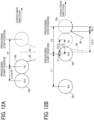
- the distance L0 (unit: millimeter, mm) from the processing start position to the processing stop position of the first object is equal to or less than the distance L1 (mm) between the first object and the second object (see an expression (i) below), and the distance L0 is less than the effective lens diameter L3 (see an expression (ii) below).
- the processing start time of the second object from the processing stop time of the first object can be sufficiently obtained, and a scanning time of a scanner, position information on the object, and orientation information on the object can be appropriately corrected. As a result, the occurrence of a defective product in the processing can be prevented.
- the distance L0 represents the shortest distance between the center of the first object at the processing start position and the center of the first object at the processing stop position.
- a lens having a suitable focal length satisfies the effective lens diameter L3.
- the distance L1 is an average value L1ave of distances of multiple objects, and the average value L1ave includes at least a minimum value L1min (mm) of the distance L1 and a maximum value L1max (mm) of the distance L1.
- a distance L1 is a distance between the first object and the second object conveyed in the conveyance direction.
- the distance L1 includes: an average value L1ave of distances between multiple objects conveyed in the conveyance direction; a minimum value L1min of the distance L1; and a maximum value L1max of the distance L1.
- the minimum value L1min and the distance L0 satisfy an expression (I) below.
- the minimum value L1min and a distance L0 from the processing start position to the processing stop position satisfy an expression (I) below: L 0 ⁇ L 1 min
- the processing start time of the second object from the processing stop time of the first object can be sufficiently obtained, a scanning time of the scanner, position information on the object, and orientation information on the object can be appropriately corrected. As a result, the occurrence of a defective product can be prevented.
- the minimum value L1min, the distance L0, and the maximum value L1max satisfy an expression (II) below.
- a condition that the distance L1 is smaller than the distance L0 by the variation of the multiple objects occurs.
- a detector can measure the distance between the first object and the second object and also calculate the position of the second object at the processing stop time of the first object based on the known conveyance velocity.
- the distance L0 (mm) and the distance L1 (mm) satisfy the expression (III) below.
- L 0 ⁇ N ⁇ L 1 where N represents the number of laser beams and is an integer of 2 or more.
- in the laser processing method further includes: scanning and irradiating the first object with multiple laser beams from a processing start position to a processing stop position of the first object.
- a distance L0 from the processing start position to the processing stop position and a distance L1 from the first object to the second object satisfy an expression (III) below: L 0 ⁇ N ⁇ L 1 where N represents a number of the multiple laser beams and an integer of two or more.
- the processing start time to the second object from a processing stop time of the first object can be sufficiently obtained, a scanning time of the scanner, position information on the object, and orientation information of the object can be appropriately corrected, and the occurrence of a defective product in the processing can be prevented.
- the object is not limited to any particular object and can be appropriately selected according to the purpose.
- the object is a container.
- a container includes a container body and a cap to seal a content within the container body.
- the container body is not limited to any particular material, shape, size, structure, and color and can be appropriately selected according to the purpose.
- the material of the container body is not limited to any particular material and can be appropriately selected according to the purpose.
- Examples of the material of the container body include resin and glass. Among these materials, transparent resin and transparent glass are preferable, and the transparent resin is more preferable.
- the resin of the container body examples include polyvinyl alcohol (PVA), polybutylene adipate terephthalate (PBAT), polyethylene terephthalate succinate, polyethylene (PE), polypropylene (PP), polyethylene terephthalate (PET), polyvinyl chloride (PVC), polystyrene (PS), polyurethane, epoxy, bio polybutylene succinate (PBS), butylene adipate co-terephthalate (PBAT), polyethylene-starch blend, poly(butylene succinate-co-terephthalate), polylactic acid (PLA), poly(3-hydroxybutyrate-co-3-hydroxyhexanoate) (PHBH), polyhydroxyalkanoate (PHA), Bio-PET 30, Bio-polyamide (PA) 610, 410, and 510, Bio-PA1012 and 10T, Bio-PA11T, MXD10, Bio polycarbonate, Bio polyurethane, Bio-Polyethylene, Bio-PET100, Bio-PA11,
- biodegradable resins such as polyvinyl alcohol, polybutylene adipate terephthalate, and polyethylene terephthalate succinate are preferable in terms of the environmental load.
- the shape of the container body is not limited to any particular shape and can be appropriately selected according to the purpose.
- Examples of the shape of the container body include a cylinder shape, a quadrangular prism shape, a box shape, a cone shape, a bottle shape, and a combination thereof. Among these shapes, a cylinder shape is preferable in terms of marking accuracy.
- the bottle-shaped container body may have an opening (i.e., finish portion or spout), a shoulder portion integrated with the opening, a sidewall portion integrated with the shoulder portion, and a bottom portion integrated with the sidewall portion.
- the size of the container body is not limited to any particular size and can be appropriately selected according to the purpose.
- the structure of the container body is not limited to any particular structure and can be appropriately selected according to the purpose.
- the structure may be a single-layer structure or a multiple-layer structure.
- Examples of the color of the container body include colorless and transparent, colored and transparent, and colored and opaque. Among these colors, colorless and transparent are preferable.
- the cap is not limited to any particular material, shape, size, structure, and color and can be appropriately selected according to the purpose.
- the material of the cap is not limited to any particular material and can be appropriately selected according to the purpose.
- Examples of the material of the cap include resin, glass, metal, and ceramic. Among these materials. resin is preferably used in terms of mouldability.
- the resin of the cap a resin similar to that of the container body of the container can be used.
- the shape and size of the cap are not limited to any particular shape and size and can be appropriately selected according to the purpose as long as the opening of the container body can be sealed.
- the structure of the cap is not limited to any particular shape and can be appropriately selected according to the purpose.
- the cap includes a first portion that is separated from the container body when opening the seal and a second portion that remains in the container body.
- the first portion has a jagged portion on the surface as an anti-slip portion when opening the sealing.
- the second portion has no jagged portion and a flat surface.
- Examples of the color of the cap include colored opaque and colored transparent. Among these colors, the colored transparent is preferable in terms of readability.
- Examples of the content include liquid, gas, and granular solid.
- liquid examples include water, tea, coffee, black tea, soft drinks, liquid detergents, and liquid cosmetics.
- the liquid beverage may be transparent, or have a color such as white, black, brown, and yellow.
- Examples of the gas include oxygen, hydrogen, and nitrogen.
- Examples of the granular solid include, pieces or granules of fruits, vegetables, nata de coco, tapioca, jelly, konjac (konnyaku, yam cake), powder detergents, and cosmetics.
- the conveying step is a step of conveying objects including the first object and the second object and at least the first object and the second object in this order, and is performed by a conveyor.
- Examples of the conveyor include a belt conveyor.
- the conveyance velocity of the object by the conveyor is not limited to any particular velocity and can be appropriately selected according to the purpose.
- the determining step is a step to determine the processing start position of the second object based on an interval from the time to detect the first object to the time to detect the second object, a conveyance velocity of the first object, and a conveyance velocity of the second object, and is performed by the determining device.
- the detecting step is a step to detect the position of an object and is performed by a detector.
- the detector detects a conveyance of the first object conveyed at a predetermined position in the case where the first object is processed by the laser beam and a conveyance of the second object conveyed at a predetermined position in the case where the second object is processed by the laser beam.
- the detector includes a light projector and a light receiver.
- the light projector may include a transmissive projector or a reflective projector.
- the detection method is not limited to any particular detection method and can be appropriately selected according to the purpose.
- the detector As a detector, various types of detector can be used depending on transparency and the shape of the object.
- the detector may include a combination of detectors.
- the detecting step includes a first detecting step and a second detecting step.
- the first detecting step when the first object is processed by a laser beam, the first detecting step detects a conveyance of the first object conveyed at a predetermined position by the detector.
- the conveyance of the second object conveyed to a predetermined position is detected by the detector.
- the processing step is a step to process an object with a laser beam, and is performed by a processing apparatus (e.g., a laser device).
- a processing apparatus e.g., a laser device
- the processing apparatus includes, for example, a laser light source, a scanner, and a light condenser.
- the laser light source is a light source that emits a laser beam.
- the laser light source is incorporated into a laser device.
- the laser light source is not limited to any particular laser light source and can be appropriately selected according to the purpose. Examples of the laser light source include an excimer laser, a Nd:YAG laser, a Nd:YVO 4 laser, and a semiconductor laser.
- the laser light source can repeatedly output a short-pulse laser beam having a constant peak intensity.
- the short-pulse laser beam includes a pulse train including multiple pulses having a constant peak intensity.
- the short-pulse laser beam is a laser beam having a pulse width of nanoseconds (ns) (1 ⁇ 10 -9 s) or less.
- the pulse width of the short-pulse laser beam is preferably in the order of femtosecond (fs) (1 ⁇ 10 -15 s) to the order of a picosecond (ps) (1 ⁇ 10 -12 s).
- the repetition frequency of the short-pulse laser beam is preferably 10 kilohertz (kHz) to 1 megahertz (MHz), and more preferably 500 kHz to 1 MHz.
- a scanner is a device to reflect the laser beam emitted from a laser light source to change its direction to a predetermined direction and to scan an object with the laser beam.
- Examples of the scanner include a galvano mirror, a polygon mirror, a micro-electromechanical systems (MEMS) mirror, and a rotating polygon mirror such as a polygon scanner.
- MEMS micro-electromechanical systems
- a light condenser condenses a laser beam.
- a light condenser includes, for example, a lens that keeps the scanning velocity of a laser beam by the scanner constant and converges the laser beam on at least any predetermined position of the object.
- Example of such a lens includes an f ⁇ lens.
- the irradiating step is a step to irradiate the second object with a laser beam by scanning the second object with the laser beam from the processing start position of the second object determined in the determining step to the processing stop position within the effective diameter of the light condenser.
- the effective lens diameter of the light condenser is the irradiation range of the laser beam, and is the diameter of the condenser lens through which the laser beam can pass.
- controller e.g., circuitry
- the controller (e.g., circuitry) is not limited to any particular controller and can be appropriately selected according to the purpose as long as the controller the controls movement of each device. Examples of the controller include a sequencer and a computer.
- a laser processing method and a laser processing apparatus will be described in detail with reference to the drawings.
- like reference signs denote like elements, and overlapping description may be simplified or omitted as appropriate.
- the number, position, and shape of the constituent members described below are not limited to those in the present embodiment, and can be set to the number, position, or shape preferable to apply the laser processing method and use the laser processing apparatus according to an embodiment of the present disclosure.
- FIG. 1 is a schematic diagram of a laser processing apparatus according to a first embodiment of the present disclosure.
- the laser processing apparatus 10 includes a laser device 11, a beam expander 12, a scanner 13, an irradiation controller 14, a light condenser 15, and a detector 16 as an optical system, and irradiates an object 18 with a laser beam 20.
- the conveyance direction of the object 18 is defined as an X-direction, and a direction orthogonal to the conveyance direction of the object 18 and different from the propagating direction of the laser beam 20 is defined as a Y-direction.
- the object 18 is conveyed downstream in the conveyance direction (i.e., the X-direction) at a conveyance velocity V.
- the conveyance direction of the object 18 is represented by an arrow, and an optical path of a laser beam 20 to the object 18 is represented by another arrow.
- the laser device 11 irradiates the object 18 with the laser beam 20 while the object is conveying.
- the object 18 is not limited to any particular object and can be appropriately selected according to the purpose as long as the object 18 is irradiated with the laser beam 20.
- the object 18 is preferably a container.
- the laser beam 20 changes a property of the container body of the container.
- each of the first object and the second object is a container.
- the laser device 11 is a device to emit a laser beam 20.
- the laser device 11 emits the laser beam 20 having an output (light intensity) suitable for changing a property of at least a surface or an inside of a base material of the object 18 irradiated with the laser beam 20.
- the type of the laser beam 20 is not limited to any particular type, but a pulse laser beam is preferable in terms of intensity.
- the laser device 11 can perform an on-off control of emission, an emission frequency control, and a light intensity control of the laser beam 20.
- the laser device 11 emits a laser beam 20 having a wavelength of 355 nm, a pulse width of 10 ps, and an average output of 30 to 50 W.
- the diameter of the laser beam 20 is preferably 1 ⁇ m to 200 ⁇ m to change the property of a region of the base material of the object 18.
- FIG. 1 only one laser device 11 is used, but multiple laser devices 11 may be used.
- the on-off control, the emission frequency control, or the light intensity control may be performed independently for each laser device 11.
- the beam expander 12 expands the laser beam.
- the diameter of a laser beam 20 of a parallel beam emitted from the laser device 11 is expanded by the beam expander 12 and enters the scanner 13.
- the scanner 13 scans the object with the laser beam 20.
- the scanner 13 includes a mirror 13a and a mirror 13b.
- the mirrors 13a and the mirror 13b have a function to change a reflection angle by a driver such as a motor.
- the mirror 13a is a scanning mirror that scans the mirror 13b with the laser beam 20 incident on the mirror 13a by changing the reflection angle parallel to the X-direction.
- Examples of the mirror 13a include a galvano mirror, a polygon mirror, and a micro-electromechanical system (MEMS) mirror.
- MEMS micro-electromechanical system
- the mirror 13a and the mirror 13b deflect the laser beam 20 as one-dimensional scanning in the X-direction, but the scanning direction is not limited thereto.
- the mirror 13a and the mirror 13b may use scanning mirrors that change the reflection angles in two directions orthogonal to each other to perform two-dimensional scanning of the laser beam 20 in the X- and Y-directions.
- the mirror 13a and the mirror 13b scan the object 18 with the laser beam 20, and at least one of the surface or the inside of the base material of the object is irradiated with the laser beam 20.
- the irradiation controller 14 outputs a signal to control the laser output to the laser device 11 and outputs a signal to scan the object with the laser beam 20 to the mirror 13b.
- the irradiation controller 14 is connected to the light receiver 16b that is a part of the detector 16, and can control the light receiver 16b to perform arithmetic and storage processing.
- the light condenser 15 condenses the laser beam.
- the light condenser 15 is a lens that keeps the scanning velocity of the laser beam 20 deflected by the mirror 13a and the mirror 13b constant and converges the laser beam 20 on at least one of the predetermined position on the surface or the inside of the base material of the object 18.
- Examples of the light condenser 15 include an f ⁇ lens and an arc sine lens that keep the scanning velocity constant.
- the light condenser 15 may include a combination of multiple lenses.
- the light condenser 15 is arranged so that the beam spot diameter of the laser beam 20 is minimized in a region of the object 18 in which the property of the base material is changed.
- FIG. 2 is a schematic diagram of the light condenser 15 in a laser processing apparatus 10 according to an embodiment of the present disclosure.
- the object 18 is processed by the laser beam 20 within an effective lens diameter L3 of the light condenser 15.
- the object 18 is irradiated with the laser beam 20 by scanning the object 18 with the laser beam 20 by the mirror 13b within a range of a chained line indicating the effective lens diameter L3 of the light condenser 15, and the object 18 is processed by the laser beam 20.
- a smaller diameter of the laser beam 20 is used because the smaller diameter of the laser beam 20 converges more energy. As a result, laser processing can be facilitated. By contrast, the laser processing becomes difficult if a larger diameter of the laser beam 20 is used. Since the beam diameter varies with a lens focal length, when a longer focal length of a lens is used, an effective lens diameter becomes larger. By contrast, when a shorter focal length of a lens is used, an effective lens diameter becomes smaller. Thus, since the effective lens diameter and the lens focal length are in a trade-off relation, a lens is designed in consideration of a balance between the focal length and the effective lens diameter.
- the detector 16 detects the position of the object 18.
- the detector 16 includes a light projector 16a and a light receiver 16b.
- the light projector 16a and the light receiver 16b detect the position of the object 18 at a point upstream from the laser device 11 in the conveyance direction.
- the detector 16 may include a transmissive detector and a reflective detector.
- the detection method of the detector 16 is not limited to any particular detection method.
- the detector 16 is a reflective detector, projects, the light projector 16a projects a light beam to the object 18 in the detector 16.
- the detector 16 detects a position of the object 18 based on a position by the light receiver 16b and a period of time until the light is received.
- the detector is 16 a transmissive detector
- the projector 16a projects a light beam to the object 18 in the detector 16 and detects a position of the object so that the light receiver 16b receives the light beam transmitted through the object 18.
- the timing of the irradiation of the laser beam 20 can be determined based on these known parameters.
- a laser processing apparatus includes: a conveyor to convey at least a first object or a second object in this order; a laser device including: a laser light source to emit a laser beam; and a light condenser to condense the laser beam emitted from the laser light source to irradiate and process the first object and the second object with the laser beam; a detector to: detect the first object conveyed to a predetermined position; detect the second object conveyed to the predetermined position; and circuitry configured to determine a processing start position of the second object from: a period of time from a time the detector detecting the first object to a time the detector detecting the second object; a conveyance velocity of the first object by the conveyor; and a conveyance velocity of the second object by the conveyor.
- the laser device scans and irradiates the second object with the laser beam from the processing start position to the processing stop position within an effective lens diameter of the light condenser.
- FIGS. 3A to 3D are schematic diagrams each illustrating the property changes of the container body of the object 18 according to an embodiment of the present disclosure.
- a portion of the surface of the container body of the object 18 is irradiated with the laser beam 20 to vaporize the portion of the surface of the container body, and a concave is formed on the surface of the container body.
- a concave is formed on the surface of the container body.
- a portion of the surface of the container body of the object 18 is irradiated with the laser beam 20 to vaporize the portion of the surface of the container body, and a concave is formed on the surface of the container body.
- the concave has protrusions at the periphery.
- the concave in FIG. 3A does not have a protrusion.
- FIG. 3C a portion of the surface of the container body of the object 18 is irradiated with the laser beam 20 to crystalize the portion of the surface of the container body. The portion of the surface of the container body is changed into a crystalline portion. As illustrated in FIG.
- a portion of the surface of the container body of the object 18 is irradiated with the laser beam 20 to foam the portion of the surface of the container body.
- the portion of the surface of the container body is changed into a foam portion.
- a portion of the surface of the container body of the object is irradiated with the laser beam 20, and the property of the container body can be changed.
- the property of the surface or the inside of the container body of the object can be changed by changing a shape portion of the surface of the container body, crystallizing a surface portion of the container body, or forming a foaming portion inside the container body.
- a method to form a concave by vaporizing a portion of the surface of the container body of the object is, for example, a method to irradiate the portion of the surface with a pulse laser beam having a wavelength of 355 nanometers (nm) to 1064 nm and a pulse width of 10 fs to 500 ns.
- a pulse laser beam having a wavelength of 355 nanometers (nm) to 1064 nm and a pulse width of 10 fs to 500 ns.
- a concave can be formed by irradiating a portion of the surface of the container body with a continuous wave (CW) laser beam having a wavelength range of 355 nm to 1064 nm and melting the portion of the surface of the container body.
- CW continuous wave
- a portion of the inside and the surface of the container body can be foamed and made opaque by continuously irradiating the portion with a laser beam even after melting the portion of the surface of the container body.
- the container body is made of, for example, polyethylene terephthalate (PET) resin
- PET polyethylene terephthalate
- the temperature of the container body is rapidly increased by irradiating the portion of the surface with a CW laser beam having a wavelength range of 355 nm to 1064 nm, and then the container body is gradually cooled by decreasing the laser power.
- a portion of the surface of the container body made of PET resin can be changed to a crystallized state, and the portion becomes opaque.
- the temperature is raised and then rapidly cooled by turning off the laser beam, the PET becomes amorphous and transparent.
- the property change of the container body of the object is not limited to those illustrated in FIGS. 3A to 3D .
- the property of the container body of the object made of resin may be changed by yellowing, oxidation, or surface modification.
- a heating control can be used to form a concave or a convex on the container body.
- the container body is coated with an absorber (i.e., a conversion material) before the container body is irradiated with the laser beam 20.
- the absorber absorbs the laser beam 20 and converts the light energy of the laser beam 20 into thermal energy.
- thermal energy By using the thermal energy, a concave or a convex on the container body can be formed.
- characters, symbols, figures, and combinations thereof can be expressed.
- FIG. 4 is a schematic diagram illustrating the processing start position of a first object in the laser processing method according to the first embodiment of the present disclosure.
- the first object is referred to as a first object 18a
- the second object is referred to as a second object 18b
- the first object 18a and the second object 18b are collectively referred to as the object 18.
- the distance L0 (mm) from the processing start position to the processing stop position and the distance L1 (mm) between the first object 18a and the second object 18b satisfy the mathematical expression (I) below.
- the processing start time to the second object 18b can be sufficiently obtained from the processing stop time of the first object 18a. Since the scanning time of the scanner, position information of the object 18, and orientation information on the object 18 can be appropriately corrected, the occurrence of a defective product can be prevented.
- the first object 18a and the second object 18b are conveyed in this order in a conveyance direction (depicted by an arrow in FIG. 4 ).
- a solid line indicates the processing start position of the first object 18a
- a dashed line indicates the processing stop position of the first object 18a.
- the two-dot chain line indicates the center of the lens (the same applies to other drawings in the following description).
- the distance L0 indicates the distance from the processing start position to the processing stop position of the first object 18a
- the distance L1 indicates a distance between the first object 18a and the second object 18b.
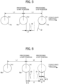
- FIG. 5 is a schematic diagram illustrating the first object while the processing is stopped according to an embodiment of the disclosure.
- the third object 18c is conveyed in the conveyance direction following the first object 18a and the second object 18b.
- the distance L1 between the first object 18a and the second object 18b is equal to the distance L1 between the second object 18b and the third object 18c.
- the second object 18b is located downstream from the processing start position of the first object 18a.
- an interval to process the second object 18b to be processed by the laser beam after the first object 18a has been processed by the laser beam is calculated by dividing a standby distance L2 (m) of the object by a conveyance velocity V (m/s) (i.e., L2/V (s)).
- t1 time for a galvano mirror to jump to the processing start position from the processing stop position
- t2 a computation time of the processing data adjusted to the detected position of the object 18 and the orientation of the object 18 after the position of the object 18 and the orientation of the object 18 are detected
- the maximum of the processing time is t1 ⁇ L2 (s) and t2 ⁇ L2 (s).
- the distance L1 between the first object 18a and the second object 18b varies depending on the accuracy of the arrangement of the object on the conveyor.
- the standby distance L2 is less than 0 (i.e., the standby distance L2 ⁇ 0). Since the laser processing apparatus 10 includes the detector 16, the standby distance L2 (m) can be calculated based on the time t3 (s) that is a difference between the time when the first object 18a passes through the detector 16 and the time when the second object 18b passes through the detector 16 and the conveyance velocity V (m/s).
- the standby distance L2 (m) is obtained by multiplying the conveyance velocity V (m/s) by the time t3 (s), and the standby time t2 (s) is obtained by dividing the obtained standby distance L2 (m) by the conveyance velocity V (m/s).
- the standby distance L2 is less than 0 (i.e., the standby distance L2 ⁇ 0)
- the laser processing is not performed on the object 18, and the object 18 is conveyed to the downstream as it is.
- the object 18 is determined as a rejected product by an inspection apparatus disposed downstream so as not to be shipped.
- FIG. 6 is a schematic diagram illustrating a condition about a distance L0 from a processing start position to a processing stop position in the laser processing method according to the first embodiment of the present disclosure.
- a laser processing method includes, detecting the second object by a detector, determining a processing start position of the second object based on an interval from a time to detect the first object to the time to detect the second object, a conveyance velocity of the first object, and a conveyance velocity of the second object, and irradiating the second object with a laser beam by scanning the second object by the laser beam from the processing start position to a processing stop position within an effective lens diameter of a light condenser.
- the laser processing method includes other steps depending on requirements.
- the variation in the distance L1 can be absorbed, and laser processing can be performed without being affected by the variation in the distance L1.
- the occurrence of a defective product can be prevented.
- an effective lens diameter is increased by the amount of the absorption.
- the laser processing can be performed without being affected by the variation of the distance L1 within the effective lens diameter, the non-processing time becomes constant, and productivity can be largely increased.
- FIG. 7 is a flowchart of laser processing in the laser processing method according to the second embodiment of the present disclosure.
- the flow of the laser processing method according to the second embodiment executed by the irradiation controller 14 in FIG. 1 will be described below with reference to FIG. 7 .
- the flow of the processing in FIG. 7 is repeatedly executed while the first object 18a and the second object 18b are sequentially conveyed, and some steps are executed in parallel.
- the second object 18b is described.
- the first object 18a is detected in step S1
- a processing start position is determined based on the detected position and a conveyance velocity of the first object 18a in step S2
- irradiating processing is performed in step S3
- conveying processing is performed in step S4.
- the process returns to step S1 to start the detection of the second object 18b.
- step S1 when the detector 16 of the laser processing apparatus 10 detects the second object 18b, the process proceeds to step S2.
- step S2 the processing start position of the second object 18b is determined based on an interval from the time to detect the first object 18a to the time to detect the second object 18b in the process of the preceding flow and the conveyance velocities of the first object 18a and the second object 18b, and then the process proceeds to step S3.
- step S3 the scanner scans the second object 18b with the laser beam 20 from the processing start position to the processing stop position to irradiate the second object 18b with the laser beam within the effective lens diameter of the light condenser in the laser processing apparatus 10, and then the process proceeds to step S4.
- step S4 the conveyor of the laser processing apparatus 10 conveys the second object 18b to a predetermined position. If there is a third object 18c (see FIG. 8 ) following the second object 18b, the process returns to step S1 again to perform the process. If there is no third object 18c after the second object 18b, the present process is finished.
- the flowchart illustrated in FIG. 7 is preferably executed as follows.
- the detecting step of step S1 in FIG. 7 includes a first detecting step of detecting that the first object 18a has been conveyed to a predetermined position by the detector in the case where the first object 18a is processed by the laser beam, and a second detecting step of detecting that the second object 18b has been conveyed to the predetermined position by the detector in the case where the second object 18b is processed by the laser beam.
- step S3 in FIG. 7 determines a processing start position based on an interval from the time to detect the first object 18a in the first detecting step to the time to detect the second object 18b in the second detecting step, and the conveyance velocity of the first object 18a, and a conveyance velocity of the second object 18b.
- the irradiating step of step S3 in FIG. 7 is a step to irradiate the second object 18b with the laser beam by scanning the second object 18b with the laser beam to the processing start position of the second object 18b determined in the determining step to the processing stop position within the effective diameter of the light condenser.
- the distance L1 between the first object 18a and the second object 18b is an average value L1ave (m) of the distances of multiple objects 18, and the average value L1ave is an average value including at least a minimum value L1min (mm) of the distance L1 and a maximum value L1max (mm) of the distance L1.
- the minimum value L1min, the distance L0, and the maximum value L1max preferably satisfy the mathematical expression (II) below.
- a distance L0 from the processing start position to the processing stop position, the minimum value L1min, and the maximum value L1max satisfy an expression (II) below: L 1 min ⁇ L 0 ⁇ L 1 max
- the detector can measure the distance between the first object 18a and the second object 18b and calculate the position of the second object 18b at the processing end of the first object from the known conveyance velocity.
- the laser processing method according to the second embodiment can perform processing when the distance L1 includes the variation, and the occurrence of defective products can be prevented.
- FIGS. 8A and 8B are schematic diagrams of laser processing in the laser processing method according to a second embodiment of the present disclosure.
- a first object 18a and a second object 18b are conveyed in this order in a conveyance direction (depicted by an arrow in the drawings).
- a solid line indicates the processing start position of the first object 18a
- a dashed line indicates the processing stop position of the first object 18a
- a two-dot chain line indicates a lens center (the same applies to other drawings in the following description).
- a minimum value L1min indicates a minimum value of a distance between the first object 18a and the second object 18b, and the minimum value L1min is equal to or less than a distance L0.
- FIG. 8B is a schematic diagram illustrating a third object 18c to be conveyed in a conveyance direction following a first object and a second object 18b.
- the minimum value L1min is the minimum value of the distance between the first object 18a and the second object 18b, and a distance L1 indicates the distance between the second object 18b and the third object 18c.
- the second object 18b is located downstream from the processing start position of the first object 18a (see FIG. 8B ).
- a conveyance velocity V (m/s) of the conveyor is constant.
- the processing start position of the second object 18b can be specified by monitoring the time of detection of the second object 18b, after the detection of the position of the first object 18a by the detector 16.
- the processing start position of the second object 18b can be determined according to the detection of the first object 18a and the detection of the second object 18b to be processed subsequently by the laser beam 20, and the laser irradiation in the processing can be controlled.
- FIGS. 9A to 11B are schematic diagrams each illustrating other laser processing in the laser processing method according to the second embodiment of the present disclosure.
- the second object 18b is specified and irradiated with the laser beam 20 by scanning the second object 18b with the laser beam from a processing start position to a processing stop position to process the second object 18b by the laser beam 20.
- the effective lens diameter L3 increases by the amount of absorption of the variation in the distance L1, but laser processing can be performed within the effective lens diameter L3 without being affected by the variation of the distance L1.
- the first object 18a and the second object 18b are conveyed in the conveyance direction depicted by an arrow in FIGA. 10A and 10B.
- the maximum value L1max indicates the maximum value of the distance between the first object 18a and the second object 18b, and the maximum value L1max is equal to or larger than the distance L0 (L0 ⁇ L1max).
- FIG. 10B is a schematic diagram illustrating a third object 18c to be conveyed in the conveyance direction following the first object 18a and the second object 18b.
- the maximum value L1max is the maximum value of the distance between the first object 18a and the second object 18b
- the distance L1 is the distance between the second object 18b and the third object 18c.
- the second object 18b is located downstream from the processing start position of the first object 18a (see FIG. 10B ).
- the processing start position of the second object 18b can be specified by monitoring the detection time of the second object 18b after detection of the first object 18a by the detector 16.
- the second object 18b is specified and irradiated with the laser beam 20 by scanning the second object 18b with the laser beam from the processing start position to the processing stop position to process the second object 18b with the laser beam 20.
- the effective lens diameter L3 increases by the amount of absorption of the variation in the distance L1, but laser processing can be performed within the effective lens diameter L3 without being affected by the variation of the distance L1.
- FIGS. 12A and 12B are schematic diagrams each illustrating the relation between the effective lens diameter L3 and the minimum value L1 in the laser processing method according to a second embodiment of the present disclosure.
- the relation between the effective lens diameter L3 and the minimum value L1min is illustrated.
- the minimum value L1min is the diameter D of the object that is the shortest distance between the first object 18a and the second object 18b adjacent to each other.
- the distance L0 required for the laser processing of the second object 18b adjacent to the first object 18a is expressed by a mathematical expression (4) below.
- the ⁇ in the mathematical expression (4) is obtained from the mathematical expression (5) below.
- the two-dot chain line in FIG. 12B represents the center of the lens.
- the first object 18a is located at the processing stop position.
- the minimum value L1min indicates that the first object 18a and the second object 18b are in contact with each other.
- the distance between the center of the second object 18b and the center of the lens in this configuration is ⁇ .
- the effective lens diameter L3 is expressed by a mathematical expression (6) below.
- L 3 3 ⁇ L 0 ⁇ 2 ⁇ D ⁇ W
- FIGS. 13A and 13B are schematic diagrams each illustrating the relation between the effective lens diameter L3 and the maximum value L1max in the laser processing method according to the second embodiment of the present disclosure.
- FIGS. 13A and 13B the relation between the effective lens diameter L3 and the maximum value L1max of the distance L1 between the first object 18a and the second object 18b is illustrated.
- the maximum value L1max is the maximum distance between the second object 18b and the first object 18a while the third object 18c and the second object 18b are adjacent to each other.
- the maximum value L1max becomes maximum in the state where the second object 18b is in contact with the third object 18c, and is expressed by a mathematical expression (7) below.
- the second object 18b and the third object 18c are in contact with each other.
- the distance between the first object 18a and the third object 18c is twice of the distance L1 and is expressed by a mathematical expression (8) below.
- the effective lens diameter L3 has a diameter that enables the second object 18b to be processed.
- the effective lens diameter L3 can be expressed by a mathematical expression (10) below.
- L 3 4 ⁇ L 1 ⁇ L 0 ⁇ 3 ⁇ D
- the effective lens diameter L3 required for the processing satisfies the mathematical expression (10) described above.
- the effective lens diameter L3 of the f920 lens is 470 mm
- the distance L1 is 150 mm
- the diameter D of the object is 20 mm
- the distance L0 is 70 mm.
- the f920 lens is a lens having a large beam diameter as a processing lens.
- a lens having a shorter focal length such as an f100 lens is used.
- preferable laser processing can be performed by changing the distance L1 and the distance L0 as long as the mathematical expression (10) described above is satisfied.
- FIGS. 14A and 14B are diagrams each illustrating an arrangement of the object in the case where multiple laser devices are disposed in the conveyance direction in the laser processing method according to the second embodiment of the present disclosure.
- FIG. 14A when multiple laser devices 11 are disposed in the conveyance direction and the objects are processed by the laser devices, a processing start position of a first object 18a1 (1 - 1st) to be processed by a (first) laser device 11 with a laser beam and a processing start position of a second object 18b1 (2 - 1st) to be processed by a (second) laser device 11 with a laser beam are illustrated.
- the first object 18a1 (1 - 1st) and the second object 18b1 (2 - 1st) in FIG. 14B are moved by the distance L0 from the first object 18a1 (1 - 1st) and the second object 18b1 (2 - 1st) in FIG. 14A .
- a processing start position of a first object 18a2 (1 - 2nd) to be processed by the (first) laser device 11 with a laser beam and a processing start position of a second object 18b2 (2 - 2nd) to be processed by the (second) laser device 11 are illustrated.
- the first object 18a1 (1 - 1st) to be processed by the (first) laser device 11 with a laser beam 20 and the second object 18b1 (2 - 1st) to be processed by the (second) laser device 11 with a laser beam 20 are conveyed at positions separated by the standby distance L2 with respect to each the laser beam 20 at the processing start position.
- first object 18a2 (1 - 2nd) to be processed by the (first) laser device 11 with a laser beam 20 and the second object 18b2 (2 - 2nd) to be processed by the (second) laser device 11 with a laser beam are conveyed at positions separated by a standby position L2 with respect to each laser beam 20 at the processing start position.
- the first object 18a1 (1 - 1st) to be processed by the (first) laser device 11 with a laser beam and the second object 18b1 (2 - 1st) to be processed by the (second) laser device 11 with a laser beam are disposed at positions separated by L1/N. As illustrated in FIG.
- the first object 18a2 (1 - 2nd) to be processed by the (first) laser device 11 with a laser beam and the second object 18b2 (2 - 2nd) to be processed by the (second) laser device 11 with a laser beam are also disposed at positions separated by L1/N.
- the laser processing method according to an embodiment of the present disclosure satisfies the distance of L0/N, and the expression (6) or expression (7) described above.
- the first object 18a to be processed by the (first) laser device 11 with a laser beam and the second object 18b to be processed by the (second) laser device 11 with a laser beam are conveyed at positions separated from each other by the standby distance L2 with respect to each laser beam 20 at the laser processing start position.
- multiple objects 18 can be processed using the multiple laser devices 11.
- a required effective lens diameter L3 can be minimized by assigning an interval between the optical axes of the laser beams of each laser device 11 to a distance L1.
- a laser processing method is a laser processing method to process multiple objects with multiple laser beams by conveying at least a first object and a second object in this order.
- a distance L0 (mm) from the processing start position to the processing stop position and a distance L1 (mm) between the first object and the second object satisfy an expression (III) below.
- L 0 ⁇ N ⁇ L 1 where N represents the number of laser beams and is an integer of 2 or more.
- the processing start time of multiple second objects 18b can be sufficiently obtained from the processing stop time of multiple first objects 18a. Since the scanning time of the scanner, the position information on the multiple objects 18, and the orientation information on the multiple objects 18 can be appropriately corrected, the occurrence of a defective product can be prevented.
- FIGS. 15A and 15B are schematic diagrams each illustrating an arrangement of objects in a laser processing method using multiple laser devices 11 according to the third embodiment of the present disclosure.
- multiple laser devices 11 are disposed in the conveyance direction, and a first object 18a1 (1 - 1st) to be processed by a (first) laser device 11 with a laser beam and a first object 18a2 (1 - 2nd) to be processed by a (second) laser device 11 with a laser beam are conveyed in this order.
- the first object 18a1 (1 - 1st) is processed by the (first) laser device 11 with the laser beam, and at the same time, the first object 18a2 (1 - 2nd) is processed by the (second) laser device 11 with the laser beam.
- a second object 18b1 (2 - 1st) to be processed by the (first) laser device 11 and a second object 18b2 (2 - 2nd) to be processed by the (second) laser device 11 are located upstream from the processing start position of the first object 18a1 (1 - 1st) processed by the (first) laser device 11 and the processing start position of the first object 18a2 (1 - 2nd) processed by the (second) laser device 11.
- each interval to process the second object 18b1 (2 - 1st) to be processed by the (first) laser device 11 and the second object 18b2 (2 - 2nd) to be processed by the (second) laser device 11 after the first object 18a1 (1 - 1st) and the first object 18a2 (1 - 2nd) have been processed by the (first) laser device 11 and the (second) laser device 11, respectively, are calculated by dividing the standby distance L2 (m) by a conveyance velocity V (m/s) of the object by (i.e., L2/S [s]).
- the maximum value of each of the processing times is L2/V (s).
- the distance L1 between the first object 18a and the second object 18b varies depending on the accuracy of the arrangement of the object on the conveyor.
- the standby distance L2 is less than 0 (i.e., the standby distance L2 ⁇ 0). Since the laser processing apparatus 10 includes the detector 16, the standby time L2 (s) can be calculated based on a time t3 [s] between a time when the first object 18a passes through the detector 16 and a time when the second object 18b passes through the detector 16 and the conveyance velocity V (m/s).
- the standby distance L2 is less than 0 (i.e., the standby distance L2 ⁇ 0)
- laser processing is not performed on the object 18.
- the object 18 is conveyed downstream as it is and determined as a rejected product by an inspection device disposed downstream. The object 18 is not shipped.
- the processing start time of the multiple objects 18 to be processed can be sufficiently obtained from the processing stop time of the multiple objects 18 processed. Since the scanning time of the scanner, the position information on the multiple objects 18, and the orientation information on the multiple objects 18 can be appropriately corrected, the occurrence of a defective product can be prevented.
Landscapes
- Physics & Mathematics (AREA)
- Optics & Photonics (AREA)
- Engineering & Computer Science (AREA)
- Mechanical Engineering (AREA)
- Plasma & Fusion (AREA)
- Laser Beam Processing (AREA)
Claims (7)
- Laserbearbeitungsverfahren, das umfasst:Fördern eines ersten Objekts und eines zweiten Objekts in einer Förderrichtung;Erfassen des an eine vorgegebene Position beförderten ersten Objekts (18a) durch einen Detektor (16);Erfassen des zweiten Objekts (18b), das durch den Detektor (16) an die vorgegebene Position befördert wurde, im Anschluss an das Erfassen des ersten Objekts (18a);Bestimmen einer Verarbeitungsstartposition des zweiten Objekts (18b) aus:einer Zeitspanne (t3) von einem Zeitpunkt der Erfassung des ersten Objekts (18a) bis zu einem Zeitpunkt der Erfassung des zweiten Objekts (18b);einer Fördergeschwindigkeit des ersten Objekts (18a); undeiner Fördergeschwindigkeit des zweiten Objekts (18b); undAbtasten und Bestrahlen des zweiten Objekts (18b) mit einem Laserstrahl (20) von der Bearbeitungsstartposition aus zu einer Bearbeitungsendposition innerhalb eines effektiven Linsendurchmessers eines Lichtkondensors (15).
- Laserbearbeitungsverfahren nach Anspruch 1,wobei das Fördern mehrere Objekte einschließlich des ersten Objekts (18a) und des zweiten Objekts (18b) fördert,eine Distanz L1 eine Distanz zwischen dem in Förderrichtung geförderten ersten Objekt (18a) und dem zweiten Objekt (18b) ist,wobei die Distanz L1 umfasst:einen Durchschnittswert L1ave von Abständen zwischen mehreren in Förderrichtung geförderten Objekten (18);einen Minimalwert L1min der Entfernung L1; undeinen Maximalwert L1max der Entfernung L1.
- Laserbearbeitungsverfahren nach Anspruch 2,
wobei der Minimalwert L1min und eine Distanz L0 von der Bearbeitungsstartposition zu der Bearbeitungsendposition dem folgenden Ausdruck (I) genügen:
- Laserbearbeitungsverfahren nach Anspruch 2,
wobei eine Distanz L0 von der Bearbeitungsstartposition zu der Bearbeitungsendposition, der Minimalwert L1min und der Maximalwert L1max einem Ausdruck (II) unten genügen:
- Laserbearbeitungsverfahren nach Anspruch 1, das weiterhin umfasst:Scannen und Bestrahlen des ersten Objekts (18a) mit mehreren Laserstrahlen von einer Bearbeitungsstartposition bis zu einer Bearbeitungsendposition des ersten Objekts (18a),wobei ein Abstand L0 von der Bearbeitungsstartposition zu der Bearbeitungsendposition und ein Abstand L1 von dem ersten Objekt (18a) zu dem zweiten Objekt (18b) einem Ausdruck (III) unten genügen:
 wobei N eine Anzahl mehrerer Laserstrahlen (20) und eine Ganzzahl von zwei oder höher ist.
 - Laserbearbeitungsverfahren nach Anspruch 1,
wobei das erste Objekt (18a) und das zweite Objekt (18b) jeweils ein Behälter sind. - Laserbearbeitungsvorrichtung, die umfasst:einen Förderer zum Fördern von mindestens einem ersten Objekt (18a) oder einem zweiten Objekt (18b) in dieser Reihenfolge;eine Laservorrichtung (11), die umfasst:eine Laserlichtquelle zum Aussenden eines Laserstrahls; undeinen Lichtkondensor (15) zum Sammeln des von der Laserlichtquelle emittierten Laserstrahls, um das erste Objekt (18a) und das zweite Objekt (18b) mit dem Laserstrahl zu bestrahlen und zu bearbeiten;einen Detektor (16) zum:Erkennen des an eine vorgegebene Position beförderten ersten Objekts (18a);Erkennen des an die vorgegebene Position beförderten zweiten Objekts (18b); undeine Schaltung, die dazu konfiguriert ist, eine Bearbeitungsstartposition des zweiten Objekts (18b) aus folgenden Elementen zu bestimmen:einer Zeitspanne (t3) von einem Zeitpunkt, an dem der Detektor das erste Objekt (18a) erkennt, bis zu einem Zeitpunkt, an dem der Detektor das zweite Objekt (18b) erkennt;einer Fördergeschwindigkeit des ersten Objekts (18a) durch den Förderer; undeiner Fördergeschwindigkeit des zweiten Objekts (18b) durch den Förderer,wobei die Laservorrichtung (11) das zweite Objekt (18b) mit dem Laserstrahl (20) von der Bearbeitungsstartposition bis zur Bearbeitungsendposition innerhalb eines effektiven Linsendurchmessers des Lichtkondensors (15) abtastet und bestrahlt.
Applications Claiming Priority (2)
| Application Number | Priority Date | Filing Date | Title |
|---|---|---|---|
| JP2022187982 | 2022-11-25 | ||
| JP2023183585A JP7509304B2 (ja) | 2022-11-25 | 2023-10-25 | レーザー加工方法及びレーザー加工装置 |
Publications (2)
| Publication Number | Publication Date |
|---|---|
| EP4400247A1 EP4400247A1 (de) | 2024-07-17 |
| EP4400247B1 true EP4400247B1 (de) | 2025-06-18 |
Family
ID=88923774
Family Applications (1)
| Application Number | Title | Priority Date | Filing Date |
|---|---|---|---|
| EP23211448.8A Active EP4400247B1 (de) | 2022-11-25 | 2023-11-22 | Laserbearbeitungsverfahren und laserbearbeitungsvorrichtung |
Country Status (2)
| Country | Link |
|---|---|
| US (1) | US20240173805A1 (de) |
| EP (1) | EP4400247B1 (de) |
Family Cites Families (2)
| Publication number | Priority date | Publication date | Assignee | Title |
|---|---|---|---|---|
| JP6829063B2 (ja) * | 2016-12-08 | 2021-02-10 | パナソニック デバイスSunx株式会社 | レーザ加工装置 |
| JP7289244B2 (ja) | 2019-09-02 | 2023-06-09 | 花王株式会社 | 被加工物の加工方法及び加工装置、並びにシート融着体の製造方法及び製造装置 |
-
2023
- 2023-11-22 EP EP23211448.8A patent/EP4400247B1/de active Active
- 2023-11-24 US US18/518,626 patent/US20240173805A1/en active Pending
Also Published As
| Publication number | Publication date |
|---|---|
| EP4400247A1 (de) | 2024-07-17 |
| US20240173805A1 (en) | 2024-05-30 |
Similar Documents
| Publication | Publication Date | Title |
|---|---|---|
| CN114746278B (zh) | 基材、容器、产品、生产方法和生产设备 | |
| US20220305812A1 (en) | Medium, container, object-holding container, marking device, and method of manufacturing container | |
| EP4074455B1 (de) | Markiervorrichtung und verfahren zur durchführung der markierung auf einem nicht-ebenen teil eines mediums | |
| US20220097414A1 (en) | Method and system for manufacturing container product | |
| EP3995249B1 (de) | Musterbildungsvorrichtung für ausgangsmaterial und musterbildungsverfahren | |
| JP7552948B2 (ja) | 収容器及び収容体 | |
| US20230166529A1 (en) | Marking method and marked receptacle | |
| JP7806397B2 (ja) | パターン形成装置 | |
| JP2022035975A (ja) | パターン形成装置 | |
| CN120712185A (zh) | 用于在制品上进行标记的高速激光过程 | |
| EP4400247A1 (de) | Laserbearbeitungsverfahren und laserbearbeitungsvorrichtung | |
| EP3695246A1 (de) | Abtastlidarsystem und verfahren mit quellenlaserstrahlaufteilungsvorrichtung und -verfahren | |
| JP7509304B2 (ja) | レーザー加工方法及びレーザー加工装置 | |
| US12459055B2 (en) | Laser irradiation apparatus and laser irradiation method | |
| KR20230111462A (ko) | 펨토초 레이저를 이용한 플라스틱 포장재 패터닝 방법 | |
| CN118081064A (zh) | 激光加工方法及激光加工装置 | |
| EP4261008A1 (de) | Verfahren zur herstellung eines harzbehälters und vorrichtung zur herstellung eines harzbehälters | |
| US20230150066A1 (en) | Laser processing apparatus and laser processing method | |
| EP4261009B1 (de) | Verfahren zur herstellung eines harzbehälters und vorrichtung zur herstellung eines harzbehälters | |
| JP7732263B2 (ja) | 収容容器及び収容体 | |
| EP2983106B1 (de) | Verfahren zum drucken eines kodes auf ein produkt | |
| US20230237292A1 (en) | Laser processing system and light irradiator | |
| JP7647433B2 (ja) | レーザーマーキング装置 | |
| JP2023155885A (ja) | 樹脂容器の製造方法及び樹脂容器の製造装置 | |
| JP2023155886A (ja) | 樹脂容器の製造方法及び樹脂容器の製造装置 |
Legal Events
| Date | Code | Title | Description |
|---|---|---|---|
| PUAI | Public reference made under article 153(3) epc to a published international application that has entered the european phase |
Free format text: ORIGINAL CODE: 0009012 |
|
| STAA | Information on the status of an ep patent application or granted ep patent |
Free format text: STATUS: REQUEST FOR EXAMINATION WAS MADE |
|
| 17P | Request for examination filed |
Effective date: 20231122 |
|
| AK | Designated contracting states |
Kind code of ref document: A1 Designated state(s): AL AT BE BG CH CY CZ DE DK EE ES FI FR GB GR HR HU IE IS IT LI LT LU LV MC ME MK MT NL NO PL PT RO RS SE SI SK SM TR |
|
| GRAP | Despatch of communication of intention to grant a patent |
Free format text: ORIGINAL CODE: EPIDOSNIGR1 |
|
| STAA | Information on the status of an ep patent application or granted ep patent |
Free format text: STATUS: GRANT OF PATENT IS INTENDED |
|
| INTG | Intention to grant announced |
Effective date: 20250114 |
|
| GRAS | Grant fee paid |
Free format text: ORIGINAL CODE: EPIDOSNIGR3 |
|
| GRAA | (expected) grant |
Free format text: ORIGINAL CODE: 0009210 |
|
| STAA | Information on the status of an ep patent application or granted ep patent |
Free format text: STATUS: THE PATENT HAS BEEN GRANTED |
|
| AK | Designated contracting states |
Kind code of ref document: B1 Designated state(s): AL AT BE BG CH CY CZ DE DK EE ES FI FR GB GR HR HU IE IS IT LI LT LU LV MC ME MK MT NL NO PL PT RO RS SE SI SK SM TR |
|
| P01 | Opt-out of the competence of the unified patent court (upc) registered |
Free format text: CASE NUMBER: APP_22937/2025 Effective date: 20250514 |
|
| REG | Reference to a national code |
Ref country code: GB Ref legal event code: FG4D |
|
| REG | Reference to a national code |
Ref country code: CH Ref legal event code: EP |
|
| REG | Reference to a national code |
Ref country code: DE Ref legal event code: R096 Ref document number: 602023004099 Country of ref document: DE |
|
| REG | Reference to a national code |
Ref country code: CH Ref legal event code: EP |
|
| REG | Reference to a national code |
Ref country code: IE Ref legal event code: FG4D |
|
| PG25 | Lapsed in a contracting state [announced via postgrant information from national office to epo] |
Ref country code: FI Free format text: LAPSE BECAUSE OF FAILURE TO SUBMIT A TRANSLATION OF THE DESCRIPTION OR TO PAY THE FEE WITHIN THE PRESCRIBED TIME-LIMIT Effective date: 20250618 |
|
| REG | Reference to a national code |
Ref country code: LT Ref legal event code: MG9D |
|
| PG25 | Lapsed in a contracting state [announced via postgrant information from national office to epo] |
Ref country code: GR Free format text: LAPSE BECAUSE OF FAILURE TO SUBMIT A TRANSLATION OF THE DESCRIPTION OR TO PAY THE FEE WITHIN THE PRESCRIBED TIME-LIMIT Effective date: 20250919 Ref country code: NO Free format text: LAPSE BECAUSE OF FAILURE TO SUBMIT A TRANSLATION OF THE DESCRIPTION OR TO PAY THE FEE WITHIN THE PRESCRIBED TIME-LIMIT Effective date: 20250918 |
|
| PG25 | Lapsed in a contracting state [announced via postgrant information from national office to epo] |
Ref country code: BG Free format text: LAPSE BECAUSE OF FAILURE TO SUBMIT A TRANSLATION OF THE DESCRIPTION OR TO PAY THE FEE WITHIN THE PRESCRIBED TIME-LIMIT Effective date: 20250618 |
|
| PG25 | Lapsed in a contracting state [announced via postgrant information from national office to epo] |
Ref country code: HR Free format text: LAPSE BECAUSE OF FAILURE TO SUBMIT A TRANSLATION OF THE DESCRIPTION OR TO PAY THE FEE WITHIN THE PRESCRIBED TIME-LIMIT Effective date: 20250618 |
|
| PG25 | Lapsed in a contracting state [announced via postgrant information from national office to epo] |
Ref country code: RS Free format text: LAPSE BECAUSE OF FAILURE TO SUBMIT A TRANSLATION OF THE DESCRIPTION OR TO PAY THE FEE WITHIN THE PRESCRIBED TIME-LIMIT Effective date: 20250918 |
|
| REG | Reference to a national code |
Ref country code: NL Ref legal event code: MP Effective date: 20250618 |
|
| PG25 | Lapsed in a contracting state [announced via postgrant information from national office to epo] |
Ref country code: LV Free format text: LAPSE BECAUSE OF FAILURE TO SUBMIT A TRANSLATION OF THE DESCRIPTION OR TO PAY THE FEE WITHIN THE PRESCRIBED TIME-LIMIT Effective date: 20250618 |
|
| PG25 | Lapsed in a contracting state [announced via postgrant information from national office to epo] |
Ref country code: NL Free format text: LAPSE BECAUSE OF FAILURE TO SUBMIT A TRANSLATION OF THE DESCRIPTION OR TO PAY THE FEE WITHIN THE PRESCRIBED TIME-LIMIT Effective date: 20250618 |
|
| PG25 | Lapsed in a contracting state [announced via postgrant information from national office to epo] |
Ref country code: PT Free format text: LAPSE BECAUSE OF FAILURE TO SUBMIT A TRANSLATION OF THE DESCRIPTION OR TO PAY THE FEE WITHIN THE PRESCRIBED TIME-LIMIT Effective date: 20251020 |
|
| REG | Reference to a national code |
Ref country code: AT Ref legal event code: MK05 Ref document number: 1803778 Country of ref document: AT Kind code of ref document: T Effective date: 20250618 |
|
| PG25 | Lapsed in a contracting state [announced via postgrant information from national office to epo] |
Ref country code: IS Free format text: LAPSE BECAUSE OF FAILURE TO SUBMIT A TRANSLATION OF THE DESCRIPTION OR TO PAY THE FEE WITHIN THE PRESCRIBED TIME-LIMIT Effective date: 20251018 |
|
| PGFP | Annual fee paid to national office [announced via postgrant information from national office to epo] |
Ref country code: DE Payment date: 20251119 Year of fee payment: 3 |
|
| PG25 | Lapsed in a contracting state [announced via postgrant information from national office to epo] |
Ref country code: AT Free format text: LAPSE BECAUSE OF FAILURE TO SUBMIT A TRANSLATION OF THE DESCRIPTION OR TO PAY THE FEE WITHIN THE PRESCRIBED TIME-LIMIT Effective date: 20250618 Ref country code: SM Free format text: LAPSE BECAUSE OF FAILURE TO SUBMIT A TRANSLATION OF THE DESCRIPTION OR TO PAY THE FEE WITHIN THE PRESCRIBED TIME-LIMIT Effective date: 20250618 |
|
| PGFP | Annual fee paid to national office [announced via postgrant information from national office to epo] |
Ref country code: FR Payment date: 20251126 Year of fee payment: 3 |
|
| PG25 | Lapsed in a contracting state [announced via postgrant information from national office to epo] |
Ref country code: CZ Free format text: LAPSE BECAUSE OF FAILURE TO SUBMIT A TRANSLATION OF THE DESCRIPTION OR TO PAY THE FEE WITHIN THE PRESCRIBED TIME-LIMIT Effective date: 20250618 |
|
| PG25 | Lapsed in a contracting state [announced via postgrant information from national office to epo] |
Ref country code: PL Free format text: LAPSE BECAUSE OF FAILURE TO SUBMIT A TRANSLATION OF THE DESCRIPTION OR TO PAY THE FEE WITHIN THE PRESCRIBED TIME-LIMIT Effective date: 20250618 |
|
| PG25 | Lapsed in a contracting state [announced via postgrant information from national office to epo] |
Ref country code: EE Free format text: LAPSE BECAUSE OF FAILURE TO SUBMIT A TRANSLATION OF THE DESCRIPTION OR TO PAY THE FEE WITHIN THE PRESCRIBED TIME-LIMIT Effective date: 20250618 |
|
| PG25 | Lapsed in a contracting state [announced via postgrant information from national office to epo] |
Ref country code: SK Free format text: LAPSE BECAUSE OF FAILURE TO SUBMIT A TRANSLATION OF THE DESCRIPTION OR TO PAY THE FEE WITHIN THE PRESCRIBED TIME-LIMIT Effective date: 20250618 |
|
| PG25 | Lapsed in a contracting state [announced via postgrant information from national office to epo] |
Ref country code: ES Free format text: LAPSE BECAUSE OF FAILURE TO SUBMIT A TRANSLATION OF THE DESCRIPTION OR TO PAY THE FEE WITHIN THE PRESCRIBED TIME-LIMIT Effective date: 20250618 |
|
| PG25 | Lapsed in a contracting state [announced via postgrant information from national office to epo] |
Ref country code: RO Free format text: LAPSE BECAUSE OF FAILURE TO SUBMIT A TRANSLATION OF THE DESCRIPTION OR TO PAY THE FEE WITHIN THE PRESCRIBED TIME-LIMIT Effective date: 20250618 |
|
| REG | Reference to a national code |
Ref country code: DE Ref legal event code: R097 Ref document number: 602023004099 Country of ref document: DE |
|
| PG25 | Lapsed in a contracting state [announced via postgrant information from national office to epo] |
Ref country code: DK Free format text: LAPSE BECAUSE OF FAILURE TO SUBMIT A TRANSLATION OF THE DESCRIPTION OR TO PAY THE FEE WITHIN THE PRESCRIBED TIME-LIMIT Effective date: 20250618 |
|
| PG25 | Lapsed in a contracting state [announced via postgrant information from national office to epo] |
Ref country code: IT Free format text: LAPSE BECAUSE OF FAILURE TO SUBMIT A TRANSLATION OF THE DESCRIPTION OR TO PAY THE FEE WITHIN THE PRESCRIBED TIME-LIMIT Effective date: 20250618 |
|
| PLBE | No opposition filed within time limit |
Free format text: ORIGINAL CODE: 0009261 |
|
| STAA | Information on the status of an ep patent application or granted ep patent |
Free format text: STATUS: NO OPPOSITION FILED WITHIN TIME LIMIT |
|
| REG | Reference to a national code |
Ref country code: CH Ref legal event code: L10 Free format text: ST27 STATUS EVENT CODE: U-0-0-L10-L00 (AS PROVIDED BY THE NATIONAL OFFICE) Effective date: 20260430 |