EP4400146A2 - Beatmungsgerät mit schaltventil - Google Patents
Beatmungsgerät mit schaltventil Download PDFInfo
- Publication number
- EP4400146A2 EP4400146A2 EP24178290.3A EP24178290A EP4400146A2 EP 4400146 A2 EP4400146 A2 EP 4400146A2 EP 24178290 A EP24178290 A EP 24178290A EP 4400146 A2 EP4400146 A2 EP 4400146A2
- Authority
- EP
- European Patent Office
- Prior art keywords
- breathing gas
- gas path
- check valve
- bypass
- switching valve
- Prior art date
- Legal status (The legal status is an assumption and is not a legal conclusion. Google has not performed a legal analysis and makes no representation as to the accuracy of the status listed.)
- Granted
Links
Images



Classifications
-
- A—HUMAN NECESSITIES
- A61—MEDICAL OR VETERINARY SCIENCE; HYGIENE
- A61M—DEVICES FOR INTRODUCING MEDIA INTO, OR ONTO, THE BODY; DEVICES FOR TRANSDUCING BODY MEDIA OR FOR TAKING MEDIA FROM THE BODY; DEVICES FOR PRODUCING OR ENDING SLEEP OR STUPOR
- A61M16/00—Devices for influencing the respiratory system of patients by gas treatment, e.g. ventilators; Tracheal tubes
-
- A—HUMAN NECESSITIES
- A61—MEDICAL OR VETERINARY SCIENCE; HYGIENE
- A61M—DEVICES FOR INTRODUCING MEDIA INTO, OR ONTO, THE BODY; DEVICES FOR TRANSDUCING BODY MEDIA OR FOR TAKING MEDIA FROM THE BODY; DEVICES FOR PRODUCING OR ENDING SLEEP OR STUPOR
- A61M16/00—Devices for influencing the respiratory system of patients by gas treatment, e.g. ventilators; Tracheal tubes
- A61M16/0057—Pumps therefor
-
- A—HUMAN NECESSITIES
- A61—MEDICAL OR VETERINARY SCIENCE; HYGIENE
- A61M—DEVICES FOR INTRODUCING MEDIA INTO, OR ONTO, THE BODY; DEVICES FOR TRANSDUCING BODY MEDIA OR FOR TAKING MEDIA FROM THE BODY; DEVICES FOR PRODUCING OR ENDING SLEEP OR STUPOR
- A61M16/00—Devices for influencing the respiratory system of patients by gas treatment, e.g. ventilators; Tracheal tubes
- A61M16/021—Devices for influencing the respiratory system of patients by gas treatment, e.g. ventilators; Tracheal tubes operated by electrical means
- A61M16/022—Control means therefor
-
- A—HUMAN NECESSITIES
- A61—MEDICAL OR VETERINARY SCIENCE; HYGIENE
- A61M—DEVICES FOR INTRODUCING MEDIA INTO, OR ONTO, THE BODY; DEVICES FOR TRANSDUCING BODY MEDIA OR FOR TAKING MEDIA FROM THE BODY; DEVICES FOR PRODUCING OR ENDING SLEEP OR STUPOR
- A61M16/00—Devices for influencing the respiratory system of patients by gas treatment, e.g. ventilators; Tracheal tubes
- A61M16/08—Bellows; Connecting tubes ; Water traps; Patient circuits
- A61M16/0883—Circuit type
-
- A—HUMAN NECESSITIES
- A61—MEDICAL OR VETERINARY SCIENCE; HYGIENE
- A61M—DEVICES FOR INTRODUCING MEDIA INTO, OR ONTO, THE BODY; DEVICES FOR TRANSDUCING BODY MEDIA OR FOR TAKING MEDIA FROM THE BODY; DEVICES FOR PRODUCING OR ENDING SLEEP OR STUPOR
- A61M16/00—Devices for influencing the respiratory system of patients by gas treatment, e.g. ventilators; Tracheal tubes
- A61M16/10—Preparation of respiratory gases or vapours
-
- A—HUMAN NECESSITIES
- A61—MEDICAL OR VETERINARY SCIENCE; HYGIENE
- A61M—DEVICES FOR INTRODUCING MEDIA INTO, OR ONTO, THE BODY; DEVICES FOR TRANSDUCING BODY MEDIA OR FOR TAKING MEDIA FROM THE BODY; DEVICES FOR PRODUCING OR ENDING SLEEP OR STUPOR
- A61M16/00—Devices for influencing the respiratory system of patients by gas treatment, e.g. ventilators; Tracheal tubes
- A61M16/10—Preparation of respiratory gases or vapours
- A61M16/12—Preparation of respiratory gases or vapours by mixing different gases
-
- A—HUMAN NECESSITIES
- A61—MEDICAL OR VETERINARY SCIENCE; HYGIENE
- A61M—DEVICES FOR INTRODUCING MEDIA INTO, OR ONTO, THE BODY; DEVICES FOR TRANSDUCING BODY MEDIA OR FOR TAKING MEDIA FROM THE BODY; DEVICES FOR PRODUCING OR ENDING SLEEP OR STUPOR
- A61M16/00—Devices for influencing the respiratory system of patients by gas treatment, e.g. ventilators; Tracheal tubes
- A61M16/20—Valves specially adapted to medical respiratory devices
- A61M16/201—Controlled valves
-
- A—HUMAN NECESSITIES
- A61—MEDICAL OR VETERINARY SCIENCE; HYGIENE
- A61M—DEVICES FOR INTRODUCING MEDIA INTO, OR ONTO, THE BODY; DEVICES FOR TRANSDUCING BODY MEDIA OR FOR TAKING MEDIA FROM THE BODY; DEVICES FOR PRODUCING OR ENDING SLEEP OR STUPOR
- A61M16/00—Devices for influencing the respiratory system of patients by gas treatment, e.g. ventilators; Tracheal tubes
- A61M16/20—Valves specially adapted to medical respiratory devices
- A61M16/208—Non-controlled one-way valves, e.g. exhalation, check, pop-off non-rebreathing valves
-
- A—HUMAN NECESSITIES
- A61—MEDICAL OR VETERINARY SCIENCE; HYGIENE
- A61M—DEVICES FOR INTRODUCING MEDIA INTO, OR ONTO, THE BODY; DEVICES FOR TRANSDUCING BODY MEDIA OR FOR TAKING MEDIA FROM THE BODY; DEVICES FOR PRODUCING OR ENDING SLEEP OR STUPOR
- A61M16/00—Devices for influencing the respiratory system of patients by gas treatment, e.g. ventilators; Tracheal tubes
- A61M16/0003—Accessories therefor, e.g. sensors, vibrators, negative pressure
-
- A—HUMAN NECESSITIES
- A61—MEDICAL OR VETERINARY SCIENCE; HYGIENE
- A61M—DEVICES FOR INTRODUCING MEDIA INTO, OR ONTO, THE BODY; DEVICES FOR TRANSDUCING BODY MEDIA OR FOR TAKING MEDIA FROM THE BODY; DEVICES FOR PRODUCING OR ENDING SLEEP OR STUPOR
- A61M16/00—Devices for influencing the respiratory system of patients by gas treatment, e.g. ventilators; Tracheal tubes
- A61M16/0057—Pumps therefor
- A61M16/0066—Blowers or centrifugal pumps
-
- A—HUMAN NECESSITIES
- A61—MEDICAL OR VETERINARY SCIENCE; HYGIENE
- A61M—DEVICES FOR INTRODUCING MEDIA INTO, OR ONTO, THE BODY; DEVICES FOR TRANSDUCING BODY MEDIA OR FOR TAKING MEDIA FROM THE BODY; DEVICES FOR PRODUCING OR ENDING SLEEP OR STUPOR
- A61M16/00—Devices for influencing the respiratory system of patients by gas treatment, e.g. ventilators; Tracheal tubes
- A61M16/10—Preparation of respiratory gases or vapours
- A61M16/1005—Preparation of respiratory gases or vapours with O2 features or with parameter measurement
-
- A—HUMAN NECESSITIES
- A61—MEDICAL OR VETERINARY SCIENCE; HYGIENE
- A61M—DEVICES FOR INTRODUCING MEDIA INTO, OR ONTO, THE BODY; DEVICES FOR TRANSDUCING BODY MEDIA OR FOR TAKING MEDIA FROM THE BODY; DEVICES FOR PRODUCING OR ENDING SLEEP OR STUPOR
- A61M16/00—Devices for influencing the respiratory system of patients by gas treatment, e.g. ventilators; Tracheal tubes
- A61M16/0003—Accessories therefor, e.g. sensors, vibrators, negative pressure
- A61M2016/003—Accessories therefor, e.g. sensors, vibrators, negative pressure with a flowmeter
- A61M2016/0033—Accessories therefor, e.g. sensors, vibrators, negative pressure with a flowmeter electrical
- A61M2016/0039—Accessories therefor, e.g. sensors, vibrators, negative pressure with a flowmeter electrical in the inspiratory circuit
-
- A—HUMAN NECESSITIES
- A61—MEDICAL OR VETERINARY SCIENCE; HYGIENE
- A61M—DEVICES FOR INTRODUCING MEDIA INTO, OR ONTO, THE BODY; DEVICES FOR TRANSDUCING BODY MEDIA OR FOR TAKING MEDIA FROM THE BODY; DEVICES FOR PRODUCING OR ENDING SLEEP OR STUPOR
- A61M16/00—Devices for influencing the respiratory system of patients by gas treatment, e.g. ventilators; Tracheal tubes
- A61M16/0003—Accessories therefor, e.g. sensors, vibrators, negative pressure
- A61M2016/003—Accessories therefor, e.g. sensors, vibrators, negative pressure with a flowmeter
- A61M2016/0033—Accessories therefor, e.g. sensors, vibrators, negative pressure with a flowmeter electrical
- A61M2016/0042—Accessories therefor, e.g. sensors, vibrators, negative pressure with a flowmeter electrical in the expiratory circuit
-
- A—HUMAN NECESSITIES
- A61—MEDICAL OR VETERINARY SCIENCE; HYGIENE
- A61M—DEVICES FOR INTRODUCING MEDIA INTO, OR ONTO, THE BODY; DEVICES FOR TRANSDUCING BODY MEDIA OR FOR TAKING MEDIA FROM THE BODY; DEVICES FOR PRODUCING OR ENDING SLEEP OR STUPOR
- A61M2202/00—Special media to be introduced, removed or treated
- A61M2202/02—Gases
- A61M2202/0208—Oxygen
-
- A—HUMAN NECESSITIES
- A61—MEDICAL OR VETERINARY SCIENCE; HYGIENE
- A61M—DEVICES FOR INTRODUCING MEDIA INTO, OR ONTO, THE BODY; DEVICES FOR TRANSDUCING BODY MEDIA OR FOR TAKING MEDIA FROM THE BODY; DEVICES FOR PRODUCING OR ENDING SLEEP OR STUPOR
- A61M2205/00—General characteristics of the apparatus
- A61M2205/33—Controlling, regulating or measuring
- A61M2205/3331—Pressure; Flow
- A61M2205/3334—Measuring or controlling the flow rate
-
- A—HUMAN NECESSITIES
- A61—MEDICAL OR VETERINARY SCIENCE; HYGIENE
- A61M—DEVICES FOR INTRODUCING MEDIA INTO, OR ONTO, THE BODY; DEVICES FOR TRANSDUCING BODY MEDIA OR FOR TAKING MEDIA FROM THE BODY; DEVICES FOR PRODUCING OR ENDING SLEEP OR STUPOR
- A61M2205/00—General characteristics of the apparatus
- A61M2205/75—General characteristics of the apparatus with filters
Definitions
- the present invention relates to a ventilator with a device inlet and a device outlet and a respiratory gas path between the device inlet and the device outlet, wherein a respiratory gas drive, a check valve and a switching valve are arranged in the respiratory gas path.
- Ventilators are used for the treatment of respiratory disorders. Ventilators can be used in non-invasive and invasive ventilation, both in-hospital and out-of-hospital.
- a ventilator with an inspiratory branch for the respiratory gas flow and optionally with a branch for the expiratory respiratory gas flow can usually be used.
- the branch for the expiratory respiratory gas flow enables the patient to exhale/exhale a respiratory gas, while the branch for the inspiratory respiratory gas flow supplies the patient with respiratory gas.
- a blockage/disturbance in the expiratory branch can be caused, for example, by the entry of material such as medication or secretion. Blockages/disturbances in the expiratory branch can prevent a patient from exhaling respiratory gas.
- a blockage/disturbance of the expiratory branch can lead to the airway pressure not being reduced to the desired pressure level during expiration, which means that a patient cannot exhale.
- a persistently increased respiratory gas pressure in the patient's airways can have harmful consequences. For example, it can lead to a dangerous increase in intrathoracic pressure, which leads to reduced venous return, reduced cardiac output and ultimately to a drop in arterial blood pressure.
- a blockage/disturbance in the inspiratory branch of the ventilator can also occur.
- a blockage/disturbance in the inspiratory branch can be caused, for example, by a failure of the respiratory gas drive. Blockages/disturbances in the inspiratory branch can prevent patients from inhaling or at least make it more difficult.
- the ventilators known in the state of the art therefore have the disadvantage that, even if safety devices are present, they are not sufficiently protected against blockages, malfunctions or failures, so that inspiration and/or expiration of respiratory gas cannot be ensured.
- the subject of the present invention is a ventilator with at least one device inlet and one device outlet and a respiratory gas path between the device inlet and the device outlet, wherein a respiratory gas drive, a check valve and a switching valve are arranged in the respiratory gas path.
- the respiratory gas path is usually an inspiratory respiratory gas path.
- the ventilator can comprise at least one inspiratory respiratory gas path and at least one expiratory respiratory gas path.
- at least one check valve is arranged in at least one inspiratory respiratory gas path.
- the check valve can be arranged between the device inlet and the respiratory gas drive.
- the check valve can be arranged between the respiratory gas drive and the device outlet.
- a respiratory gas drive can be a blower or a pressure source, in particular an oxygen or air pressure source.
- the check valve prevents a flow of breathing gas in one direction from the device outlet to the device inlet and the switching valve enables a flow of breathing gas in one direction from the device outlet to the device inlet or to a separate device opening, at least temporarily.
- the separate device opening can be a second/separate device inlet or a second/separate device outlet.
- a switching valve can be electromechanical.
- a switching valve can be a pneumatic valve with a magnetic valve or a bypass with a solenoid valve.
- a switching valve can be a 3/2-way valve, a pneumatic valve or a diaphragm valve.
- the patient's exhaled breathing gas can be discharged via an expiratory breathing gas path of the ventilator.
- This can prevent the breathing gas from being returned via the inspiratory breathing gas path.
- the check valve prevents unwanted contamination of the breathing gas drive with contaminated breathing gas from the patient during normal operation of the ventilator.
- the included switching valve can be used to bypass the check valve at least temporarily if the expiratory breathing gas path is blocked/disrupted. This offers the advantage that if the expiratory breathing gas path is blocked, the patient's breathing gas can be discharged via the inspiratory breathing gas path.
- a flow measuring device is arranged between the check valve and the device outlet.
- the flow measuring device is designed to detect a flow or a volume or a pressure of the respiratory gas in the respiratory gas path.
- the switching valve is designed to be openable or closable based on the detected flow or volume or pressure of the respiratory gas. This enables the switching valve to be switched depending on the respiratory gas volume or pressure.
- the switching valve can be controlled in a time-controlled or patient-triggered manner.
- the switching valve can be switched, for example, by a 3/2-way valve.
- the switching valve is arranged in a bypass to the check valve.
- the bypass can be open or closed. Closed means that the bypass opens into the breathing gas path from which it is branched off. and thereby bypasses the check valve.
- the switching valve is usually arranged in the bypass. Open means that the bypass does not flow into the respiratory gas path from which it branches off. Rather, an open bypass is a respiratory gas path that can, for example, have a separate/second device outlet.
- the open bypass usually branches off between the device outlet and the respiratory gas drive or the check valve and flows into the separate/second device outlet. Alternatively, the open bypass can branch off between the check valve and the respiratory gas drive and flow into the second/separate device outlet.
- a flow measuring device can be arranged in the open bypass.
- the flow measuring device is usually arranged between the second/separate device outlet and the bypass.
- a separate switching valve can be arranged in the open bypass.
- the switching valve can be time-controlled, patient-triggered or switchable based on a flow or volume or pressure of the respiratory gas recorded by the flow measuring device.
- the flow measuring device is usually located between the switching valve and the common device outlet.
- the open bypass can also be designed as a closed bypass. The open bypass offers the advantage that breathing gas released by the patient can be released into the environment via the separate/second device outlet.
- the at least one switching valve forms a bypass around the check valve.
- the check valve can be bypassed in such a way that the breathing gas is introduced around the check valve into the same breathing gas path from which it was branched off.
- the at least one switching valve forms an open bypass around the check valve. With the open bypass, breathing gas can be discharged past the check valve via the open bypass via a separate device outlet in the event of a blockage/disturbance of the inspiratory breathing gas path.
- the at least one switching valve is designed to open and/or close the bypass, wherein the switching valve is designed to be automatically or actively switchable.
- the switching valve is designed to automatically open and/or close the bypass based on the determined flow or volume or pressure of the breathing gas. to open or close. For example, the switching valve opens when the flow measuring device detects a higher pressure over a certain period of time.
- the breathing gas drive is arranged between the device inlet and the check valve and is set up to convey breathing gas in the direction of the check valve and the device outlet.
- the arrangement of the breathing gas drive defines a suction side and a pressure side in the ventilator.
- the suction side is the side in the direction of breathing gas flow upstream of the breathing gas drive.
- the pressure side is the side in the direction of breathing gas flow downstream of the breathing gas drive. Due to the arrangement of the breathing gas drive directly behind the device inlet, the check valve, the switching valve and the flow measuring device are on the pressure side of the ventilator.
- the bypass to the switching valve branches off between the breathing gas drive and the check valve and flows back into the breathing gas path between the check valve and the device outlet. This arrangement protects the breathing gas drive from unwanted contamination by recirculated breathing gas during normal operation of the ventilator.
- the breathing gas drive is arranged between the check valve and the device outlet and is designed to convey breathing gas in the direction of the device outlet.
- the check valve and the switching valve are located on the suction side of the ventilator.
- the bypass to the switching valve branches off between the device inlet and the check valve and flows back into the breathing gas path between the check valve and the breathing gas drive.
- a second breathing gas path is formed, which comprises a second device inlet and at least one check valve and leads into the first device outlet before the common device outlet.
- the second respiratory gas path is typically a separate inspiratory respiratory gas path that is designed to provide a separate respiratory gas path through which respiratory gas can be inspired in the event of a blockage/disturbance of the inspiratory respiratory gas path.
- the second inspiratory respiratory gas path can comprise a separate respiratory gas drive.
- the respiratory gas drive is arranged between the second device inlet and the check valve of the second respiratory gas path.
- the second respiratory gas path can comprise a separate flow measuring device that is designed to detect the flow or the volume or the pressure of the respiratory gas in the second respiratory gas path.
- a breathing gas path for an expiratory breathing gas flow which comprises an expiratory device inlet and an expiratory device outlet.
- the breathing gas path for an expiratory breathing gas flow is designed to discharge the patient's breathing gas.
- the expiratory device inlet is generally arranged close to the patient, while the expiratory device outlet is designed away from the patient.
- the breathing gas path for expiratory breathing gas is designed to discharge the patient's breathing gas to the expiratory device outlet and thus enable the patient to exhale.
- the respiratory gas path leads from the expiratory device inlet to the expiratory device outlet, and a switching valve and a flow measuring device are arranged in the respiratory gas path.
- the flow measuring device is usually arranged between the expiratory device outlet and the switching valve.
- the switching valve is usually set up to be switchable based on a specified time interval or a patient trigger. Alternatively, the switching valve can be switchable based on a flow or volume or pressure of the respiratory gas measured by a flow measuring device.
- the flow measuring device arranged between the expiratory device outlet and the switching valve is typically set up to record the flow or volume or pressure of the respiratory gas and to enable feedback to the ventilator about the respiratory gas delivered by the patient.
- a separate expiratory breathing gas path with a switching valve and a flow measuring device leads between the expiratory device inlet and the switching valve to a separate device outlet.
- the separate expiratory breathing gas path is designed to remove the patient's breathing gas, for example in the event of a blockage/disturbance of the expiratory breathing gas path.
- the flow measuring device arranged between the expiratory device outlet and the switching valve is typically designed to record the flow or volume or pressure of the breathing gas and to provide feedback on the breathing gas released by the patient.
- a hose system is adapted to the device outlet, which leads with a first branch to a patient interface and, in front of the patient interface, with a second branch to the expiratory device inlet for expiratory breathing gas.
- the hose system is a single hose system.
- a hose system that is a leakage hose system can be adapted to the device outlet.
- the patient interface is connected to at least one inspiratory breathing gas path through the hose system.
- the patient interface is connected to at least one inspiratory breathing gas path and at least one expiratory breathing gas path through the hose system.
- the switching valve is arranged in the bypass, wherein the bypass is designed as an open bypass which comprises a separate device outlet, wherein the open bypass branches off from the inspiratory breathing gas path between the check valve and the device outlet and opens into the separate device outlet, wherein the inspiratory breathing gas path has at least one further valve and a flow measuring device, wherein the flow measuring device is arranged between the breathing gas drive and the check valve.
- the present invention also relates to a ventilator with at least one device input and one device output and a Respiratory gas path between the device inlet and device outlet, with a respiratory gas drive, a check valve and a switching valve arranged in the respiratory gas path.
- the switching valve is arranged in the bypass, wherein the bypass is designed as an open bypass which comprises a separate device outlet, wherein the open bypass branches off from the inspiratory breathing gas path between the check valve and the device outlet and opens into the separate device outlet, wherein the inspiratory breathing gas path has at least one further valve and a flow measuring device, wherein the flow measuring device is arranged between the breathing gas drive and the check valve.
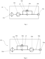
- FIG. 1 shows a schematic structure of an embodiment of a ventilator 10 according to the invention with an inspiratory breathing gas path 16a with a bypass 17 and the check valve 13a.
- the inspiratory breathing gas path 16a comprises a device inlet 11a and a device outlet 15a.
- the device outlet 15a is arranged close to the patient and the device inlet 11a is arranged away from the patient.
- the breathing gas path 16a extends from the device inlet 11a to the device outlet 15a.
- the breathing gas path 16a comprises a breathing gas drive 12a, a check valve 13a and a switching valve 14a.
- the switching valve 14a is arranged in a bypass 17 to the check valve 13a.
- the bypass 17 branches off between the breathing gas drive 12a and the check valve 13a and flows back into the inspiratory breathing gas path 16a between the check valve 13a and the device outlet 15a.
- the breathing gas drive 12a is arranged between the device inlet 11a and the check valve 13a. Breathing gas can be returned to the device inlet 11a via the switching valve 14a arranged in the bypass 17, thereby bypassing the check valve 13a.
- FIG 2 shows an alternative arrangement of the Figure 1 shown embodiment of the ventilator 10 according to the invention with the inspiratory breathing gas path 16a with the bypass 17 around the check valve 13a.
- the inspiratory breathing gas path 16a comprises the device inlet 11a and the device outlet 15a.
- the breathing gas path 16a extends from the device inlet 11a to the device outlet 15a.
- the breathing gas path 16a comprises the check valve 13a, the breathing gas drive 12a and the switching valve 14a.
- the switching valve 14a is arranged in the bypass 17 to the check valve 13a.
- the bypass 17 branches in this alternative arrangement between the Device inlet 11a and the non-return valve 13a and flows back into the inspiratory breathing gas path 16a between the non-return valve 13a and the breathing gas drive 12a.
- the breathing gas drive 12a is arranged between the non-return valve 13a and the device outlet 15a. Breathing gas can be returned to the device inlet 11a via the switching valve 14a arranged in the bypass 17 after it has passed the
- FIG 3 shows a schematic structure of another embodiment of the Figure 1 shown ventilator 10 according to the invention, with the inspiratory breathing gas path 16a, the bypass 17 and a second inspiratory breathing gas path 16b.
- the inspiratory breathing gas path 16a extends from the device inlet 11a to the device outlet 15a.
- the inspiratory breathing gas path 16a comprises the breathing gas drive 12a, the check valve 14a and the switching valve 14a, wherein the switching valve 14a is arranged in the bypass 17 to bypass the check valve 13a.
- the in Figure 3 The embodiment of the ventilator 10 shown has a second inspiratory breathing gas path 16b which extends from a second device inlet 11b to the common device outlet 15a.
- the second inspiratory breathing gas path 16b opens into the inspiratory breathing gas path 16a between the check valve 13a and the common device outlet 15a.
- the second inspiratory breathing gas path 16b can comprise a check valve 13b. If the inspiratory breathing gas path 16a is blocked/disturbed, for example, breathing gas can be drawn from the second inspiratory breathing gas path 16b via the separate device inlet 11b and supplied to the patient. In addition, if an expiratory breathing gas path is blocked, breathing gas can be returned by bypassing the check valve 13a through the switching valve 14a, allowing the patient to exhale.
- Figure 4 shows an alternative arrangement of the Figure 2 shown embodiment of the ventilator 10 according to the invention, with the inspiratory breathing gas path 16a, the bypass 17 and the second inspiratory breathing gas path 16b.
- the check valve 13a is arranged in the inspiratory breathing gas path 16a between the device inlet 11a and the breathing gas drive 12a.
- the bypass 17 is designed as a check valve 13a, which branches off between the device inlet 11a and flows back into the inspiratory breathing gas path 16a between the check valve 13a and the breathing gas drive 12a.
- the breathing gas drive 12a is arranged between the check valve 13a and the device outlet 15a.
- the second inspiratory breathing gas path 16b flows into the inspiratory breathing gas path 16a between the breathing gas drive 12a and the common device outlet 15a.
- the second inspiratory breathing gas path 16b can comprise a check valve 13b.
- breathing gas can also be drawn via the second inspiratory breathing gas path 16b via the separate device inlet 11b and supplied to the patient, for example in the event of a blockage/disturbance of the inspiratory breathing gas path 16a.
- respiratory gas can be recirculated through the switching valve 14a by bypassing the check valve 13a, allowing the patient to exhale.
- Figure 5 shows an alternative arrangement of the Fig.1 and Fig.3 shown embodiment of the ventilator 10 according to the invention, with the inspiratory breathing gas path 16a, the bypass 17 and the second inspiratory breathing gas path 16b.
- the inspiratory breathing gas path 16a extends from the device inlet 11a to the device outlet 15a and comprises the breathing gas drive 12a, the check valve 14a and the switching valve 14a.
- the switching valve 14a is arranged in the bypass 17 to bypass the check valve 13a.
- the bypass 17 is formed between the breathing gas drive 12a and the device outlet 15a.
- the Figure 5 The embodiment of the ventilator 10 shown also has the second inspiratory breathing gas path 16b, which extends from the second device inlet 11b to the common device outlet 15a.
- the second inspiratory breathing gas path 16b opens into the inspiratory breathing gas path 16a between the check valve 13b and the common device outlet 15a.
- FIG 6 shows an alternative arrangement of the Figure 2 and Figure 4 shown embodiment of the ventilator 10 according to the invention, with the inspiratory breathing gas path 16a, the bypass 17 and the second inspiratory breathing gas path 16b.
- the inspiratory breathing gas path 16a extends from the device inlet 11a to the device outlet 15a and comprises the check valve 14a, the switching valve 14a and the breathing gas drive 12a.
- the switching valve 14a is arranged in the bypass 17 to bypass the check valve 13b.
- the bypass 17 with the switching valve 14a is arranged between the device inlet 11a and the breathing gas drive 12a.
- the in Figure 6 The embodiment of the ventilator 10 shown has the second inspiratory breathing gas path 16b, which extends from a second device inlet 11b to the common device outlet 15a.
- the second inspiratory breathing gas path 16b opens into the inspiratory breathing gas path 16a between the breathing gas drive 12a and the common device outlet 15a.
- the second inspiratory breathing gas path 16b has a check valve 13b and a breathing gas drive 12b, wherein the breathing gas drive 12b is arranged between the second device inlet 11b and the check valve 13b.
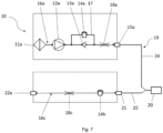
- Figure 7 a schematic structure of an embodiment of the ventilator 10 according to the invention with the inspiratory breathing gas path 16a with a bypass 17 and an expiratory breathing gas path 16c.
- the inspiratory breathing gas path 16a extends from the device inlet 11a to the device outlet 15a.
- the inspiratory breathing gas path 16a comprises the breathing gas drive 12a as well as the check valve 13a and the switching valve 14a, which is arranged in a bypass 17 to the check valve 13a, as well as a Flow measuring device 18a.
- the flow measuring device 18a is arranged between the bypass 17 and the device outlet 15a.
- the flow measuring device 18a can be used to measure a flow or a volume or a pressure of the respiratory gas in the respiratory gas path. With a predetermined volume or pressure of respiratory gas over a predetermined period of time, the switching valve can be switched, for example, using a 3/2-way valve.
- the switching valve is usually set up and designed to set a PEEP (positive end-expiratory pressure) in the range of 0-20hPa, preferably 0-15hPa.
- the expiratory breathing gas path 16c extends from an expiratory device inlet 21 to the expiratory device outlet 22a and comprises a switching valve 14b and a flow measuring device 18c.
- the flow measuring device 18c is arranged between the expiratory device outlet 22a and the switching valve 14b.
- the flow measuring device 18c serves to record a flow or a volume or a pressure of the breathing gas in the breathing gas path. Based on the values recorded by the flow measuring device 18c, feedback can be provided to the ventilator about the volume of the breathing gas delivered by the patient.
- a hose system 19 with a first branch 24 and a second branch 25 is adapted to the device outlet 15a.
- the first branch 24 leads from the device outlet 15a to a patient interface 20.
- the hose system 19 with a second branch 25 leads to the expiratory device inlet 21 for expiratory breathing gas.
- a patient interface 20 is connected to the inspiratory branch 16a and the expiratory branch 16c via the hose system 19.
- a breathing gas can be obtained via the device inlet 11a and guided via the breathing gas drive 12a through the check valve 13a in the direction of the device outlet 15a.
- the breathing gas is passed from the device outlet 15a via the branch 24 of the adapted hose system 19 to the patient interface 20, through which a patient can inhale the breathing gas.
- the patient's exhaled air can be discharged via the branch 25 of the adapted Hose system 19 is fed to the breathing gas path 16c via the expiratory device inlet 21.
- the breathing gas is guided via the expiratory breathing gas path 16c to the expiratory device outlet 22a and released into the environment. If the expiratory breathing gas path 16c is blocked/disturbed, the breathing gas can be discharged into the inspiratory breathing gas path 16a by opening the switching valve 14a in the bypass 17.
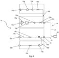
- Figure 8 shows a schematic structure of a further embodiment of the ventilator 10 according to the invention with the first inspiratory breathing gas path 16a and the second inspiratory breathing gas path 16b as well as with the expiratory breathing gas path 16c and a separate expiratory breathing gas path 16d.
- the inspiratory breathing gas path 16a extends from the device inlet 11a to the device outlet 15a.
- the inspiratory breathing gas path 16a comprises the breathing gas drive 12a, the check valve 13a and a flow measuring device 18a.
- the flow measuring device 18a is arranged between the check valve 13a and the device outlet 15a.
- the flow measuring device 18a records a flow or a volume or a pressure of the breathing gas which is delivered to the patient via the inspiratory breathing gas path 16a.
- the embodiment of the ventilator 10 shown has a second inspiratory breathing gas path 16b, which extends from the second device inlet 11b to the common device outlet 15a.
- the second inspiratory breathing gas path 16b opens into the inspiratory breathing gas path 16a between the flow measuring device and the common device outlet 15a.
- the second inspiratory breathing gas path 16b can comprise the separate breathing gas drive 12b, the check valve 13b and a flow measuring device 18b.
- the separate breathing gas drive 12b is arranged between the second device inlet 11b and the check valve 13b.
- the flow measuring device 18b can detect a volume or pressure of the inspiratory breathing gas in the breathing gas path 16b and transmit it to the ventilator 10. Via the second inspiratory breathing gas path 16b, in the case of a If the inspiratory gas pathway 16a is blocked, breathing gas can be drawn through the device inlet 11b and supplied to the patient.
- the embodiment of the ventilator 10 shown further comprises the expiratory breathing gas path 16c, which extends from the expiratory device inlet 21 to the expiratory device outlet 22a and comprises the switching valve 14b and the flow measuring device 18c.
- the flow measuring device 18c is arranged between the expiratory device outlet 22a and the switching valve 14b.
- the flow measuring device 18c records a volume and/or a pressure of the breathing gas which the patient releases. A breathing gas released by the patient can be discharged via the expiratory breathing gas path 16c.
- the flow measuring devices 18a, 18b, 18c and 18d can be configured to detect a flow or a volume or a pressure of the respiratory gas in the respiratory gas path and, based on this, to switch or open and close a switching valve or to provide feedback to the ventilator 10 about the flow or the volume or the pressure of the respiratory gas supplied to the patient or the respiratory gas released by the patient.
- the embodiment of the ventilator 10 shown also has a separate expiratory breathing gas path 16d.
- the separate expiratory breathing gas path 16d branches off from the expiratory breathing gas path 16c and extends to a separate device outlet 22b.
- the separate expiratory breathing gas path 16d comprises a switching valve 14c and a flow measuring device 18d.
- the flow measuring device 18d records a flow or a volume or a pressure of the breathing gas which the patient releases. Breathing gas released by the patient can be discharged via the separate expiratory breathing gas path 16d in the event of a blockage/disturbance of the expiratory breathing gas path 16c.
- a hose system 19 with a first branch 24 and a second branch 25 is adapted to the device outlet 15a.
- the first branch 24 leads from the device outlet 15a to a patient interface 20.
- the hose system 19 with the second branch 25 leads to the expiratory device inlet 21 for expiratory breathing gas.
- the patient interface 20 is connected to the inspiratory breathing gas path 16a, the second inspiratory breathing gas path 16b, the expiratory breathing gas path 16c and the separate expiratory breathing gas path 16d via the hose system 19.
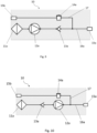
- FIG 9 shows a schematic structure of an alternative embodiment of the ventilator 10 according to the invention with the inspiratory breathing gas path 16a with an open bypass 17 with a separate device outlet 15b.
- the inspiratory breathing gas path 16a of the ventilator 10 comprises the device inlet 11a and the device outlet 15a.
- the breathing gas drive 12a, the check valve 13a and the switching valve 14a are arranged between the device inlet 11a and the device outlet 15a, with the switching valve 14a being arranged in the bypass 17.
- the bypass 17 is designed as an open bypass which comprises a separate device outlet 15b.
- the open bypass 17 branches off from the inspiratory breathing gas path 16a between the check valve 13a and the device outlet 15a and opens into the separate device outlet 15b.
- the respiratory gas drive 12a is arranged between the device inlet 11 and the check valve 13a.
- the switching valve 14a can be switched in a time-controlled manner, patient-triggered or based on a flow or volume of the respiratory gas recorded by a flow measuring device.
- the flow measuring direction is arranged between the separate device outlet 15b and the switching valve 14a.
- the switching valve 14a arranged in the open bypass 17 makes it possible to release respiratory gas emitted by the patient via the switching valve 14a if the inspiratory respiratory gas path 16a is blocked.
- the check valve 13a By arranging the check valve 13a between the respiratory gas drive 12a and the device outlet 15a, the check valve 13a is arranged on the pressure side of the ventilator 10.
- FIG 10 shows an alternative schematic structure of a Fig.9 shown embodiment of the ventilator 10 according to the invention with the inspiratory breathing gas path 16a and the open bypass 17 with the separate device outlet 15b.
- the inspiratory breathing gas path 16a of the ventilator 10 comprises the device inlet 11a and the device outlet 15a.
- the bypass 17 is designed as an open bypass which includes a separate device outlet 15b.
- the open bypass 17 branches off from the inspiratory respiratory gas path 16a between the respiratory gas drive 12a and the device outlet 15a and opens into the separate device outlet 15b.
- the respiratory gas drive 12a is arranged between the check valve 13a and the device outlet 15a.
- the switching valve 14a arranged in the open bypass 17 makes it possible to release respiratory gas emitted by the patient via the switching valve 14a in the event of a blockage in the inspiratory respiratory gas path 16a.
- breathing gas can be recirculated without having to pass through the breathing gas drive.
- the check valve 13a is arranged on the suction side of the ventilator 10.
- FIG 11 shows an alternative schematic structure of a Figures 9 and 10 shown alternative embodiment of the ventilator 10 according to the invention with the inspiratory breathing gas path 16a and the open bypass 17 with the separate device outlet 15b.
- the inspiratory breathing gas path 16a of the ventilator 10 comprises the device inlet 11a and the device outlet 15a. Between the device inlet 11a and the device outlet 15a are the breathing gas drive 12a, the check valve 13 and the switching valve 14a, with the switching valve 14a being arranged in the bypass 17.
- the bypass 17 is designed as an open bypass which comprises a separate device outlet 15b.
- the open bypass 17 branches off from the inspiratory breathing gas path 16a between the check valve 13a and the breathing gas drive 12a and opens into the separate device outlet 15b.
- the respiratory gas drive 12a is arranged between the non-return valve 13a and the device outlet 15a. Via the switching valve 14a arranged in the open bypass 17, it is possible to release respiratory gas emitted by the patient via the switching valve 14a in the event of a blockage of the inspiratory respiratory gas path 16a.
- the check valve 13a is arranged on the suction side of the ventilator 10.
- FIG 12 shows a schematic structure of an alternative embodiment of the ventilator 10 according to the invention with the inspiratory breathing gas path 16a with the open bypass 17 with the separate device outlet 15b.
- the inspiratory breathing gas path 16a of the ventilator 10 comprises the device inlet 11a and the device outlet 15a.
- the breathing gas drive 12a, the check valve 13a, a flow measuring device 27 and the switching valve 14a are arranged between the device inlet 11a and the device outlet 15a, the switching valve 14a being arranged in the bypass 17.
- the bypass 17 is designed as an open bypass which comprises a separate device outlet 15b and at least one flow measuring device 27.
- the open bypass 17 branches off from the inspiratory breathing gas path 16a between the check valve 13a and the device outlet 15a and opens into the separate device outlet 15b.
- the breathing gas drive 12a is arranged between the device inlet 11a and the check valve 13a.
- the switching valve 14a can be switched in a time-controlled manner, patient-triggered or based on a flow or volume of the breathing gas recorded by the flow measuring device 27 arranged in the bypass 17.
- the flow measuring direction 27 in the bypass 17 is arranged between the separate device outlet 15b and the switching valve 14a. Via the switching valve 14a arranged in the open bypass 17, it is possible to release breathing gas emitted by the patient via the switching valve 14a in the event of a blockage of the inspiratory breathing gas path 16a. Due to the arrangement of the check valve 13a between the breathing gas drive 12a and the device outlet 15a, the check valve 13a is arranged on the pressure side of the ventilator 10.
- the inspiratory breathing gas path 16a additionally comprises at least one further valve 26, which is designed to ensure an oxygen or air or compressed air supply to the inspiratory breathing gas path 16a.
- the inspiratory breathing gas path 16a comprises at least one flow measuring device 27, wherein the flow measuring device 27 is arranged between the breathing gas drive 12a and the Check valve 13a is arranged.
- the further valve 26 can open into the inspiratory breathing gas path 16a between the device inlet 11a and the breathing gas drive 12a and between the flow measuring device 27 and the check valve 13a.
- the further valve 26 is usually a proportional valve.
- the area of the open bypass 17 with the switching valve 14a, the flow measuring device 27 and the separate device outlet 15b as well as the area of the inspiratory breathing gas path 16a with the check valve 13a and the device outlet 15a can be removed from the ventilator and autoclaved.
- the area of the inspiratory breathing gas path 16a with the device inlet 11a, the breathing gas drive 12a and the flow measuring device 27 is set up and designed in such a way that it does not come into contact with contaminated breathing gas.
- the Figures 9 to 11 The alternative embodiments of the ventilator 10 shown each comprise a flow measuring device which detects a flow or a volume or a pressure of the respiratory gas in the respiratory gas path.
- the switching valve 14a can be used in the alternative embodiments as shown in the Figures 9 to 11 shown, can be switched based on the flow or volume detected by the flow measuring device.
- Figures 9 to 11 shown alternative embodiments with the ones shown in the Figures 1 to 8 shown embodiments.
- the device shown in the Figures 9 to 11 shown open bypass 17 the closed bypass 17 in the in the Figures 1 to 8 Replace the embodiments shown.
Landscapes
- Health & Medical Sciences (AREA)
- Pulmonology (AREA)
- Heart & Thoracic Surgery (AREA)
- Engineering & Computer Science (AREA)
- Anesthesiology (AREA)
- Biomedical Technology (AREA)
- Emergency Medicine (AREA)
- Hematology (AREA)
- Life Sciences & Earth Sciences (AREA)
- Animal Behavior & Ethology (AREA)
- General Health & Medical Sciences (AREA)
- Public Health (AREA)
- Veterinary Medicine (AREA)
- Respiratory Apparatuses And Protective Means (AREA)
- Multiple-Way Valves (AREA)
Abstract
Description
- Die vorliegende Erfindung betrifft ein Beatmungsgerät mit einem Geräteeingang und einem Geräteausgang und einem Atemgasweg zwischen Geräteeingang und Geräteausgang, wobei im Atemgasweg ein Atemgasantrieb, ein Rückschlagventil und ein Schaltventil angeordnet sind.
- Beatmungsgeräte werden für die Therapie respiratorischer Störungen eingesetzt, dabei können die Beatmungsgeräte in der nicht- invasiven und invasiven Beatmung, sowohl innerklinisch als auch außerklinisch, verwendet werden.
- Bei einer Beatmung eines Patienten kann in der Regel ein Beatmungsgerät mit einem inspiratorischen Zweig für den Atemgasfluss und optional mit einem Zweig für den exspiratorischen Atemgasfluss eingesetzt werden. Der Zweig für den exspiratorischen Atemgasfluss ermöglicht die Ausatmung/Exspiration eines Atemgases durch den Patienten, während der Zweig für den inspiratorischen Atemgasfluss den Patienten mit Atemgas versorgt.
- Bei den im Stand der Technik bekannten Beatmungsgeräten kann es zu sowohl zu Blockaden/Störungen im exspiratorischen Zweig als auch im inspiratorischen Zweig des Beatmungsgerätes kommen.
- Eine Blockade/Störung im exspiratorischen Zweig kann beispielsweise durch Materialeintrag, wie beispielsweise Medikamente oder Sekret, verursacht werden. Blockaden/Störungen im exspiratorischen Zweig können einen Patienten an einer Ausatmung von Atemgas hindern.
- Eine Blockade/Störung des exspiratorischen Zweiges kann beispielsweise dazu führen, dass der Atemwegsdruck in der Exspiration nicht auf das angestrebte Druckniveau gesenkt werden kann, wodurch ein Patient nicht ausatmen kann. Ein anhaltender erhöhter Atemgasdruck in Atemwegen des Patienten kann schädliche Folgen haben. Beispielsweise kann es zu einem gefährlichen Anstieg des intrathorakalen Drucks kommen, der zu einem verminderten venösen Rückfluss, verminderter Herzleistung und schließlich zu einem Abfall des arteriellen Blutdrucks führt.
- Neben der Problematik einer Blockade/Störung im exspiratorischen Zweig des Beatmungsgerätes kann es auch zu einer Blockade/Störung im inspiratorischen Zweig des Beatmungsgerätes kommen. Eine Blockade/Störung im inspiratorischen Zweig kann beispielsweise durch einen Ausfall des Atemgasantriebs hervorgerufen werden. Blockaden/Störungen im inspiratorischen Zweig können Patienten an einer Einatmung hindern oder diese zumindest erschweren.
- Die im Stand der Technik bekannten Beatmungsgeräte weisen somit den Nachteil auf, dass sie auch bei vorhandenen Sicherungsvorrichtungen nicht ausreichend gegen Blockaden, Störungen oder Ausfälle gesichert sind, sodass eine Inspiration und/oder Exspiration von Atemgas nicht sichergestellt werden kann.
- Es ist daher Aufgabe der vorliegenden Erfindung, ein Beatmungsgerät zur Verfügung zu stellen, das eine Sicherung einer Inspiration und/oder einer Exspiration von Atemgas bei einer Störung / Blockade eines inspiratorischen oder exspiratorischen Zweiges des Beatmungsgerätes sicherstellt.
- Gegenstand der vorliegenden Erfindung ist ein Beatmungsgerät mit mindestens einem Geräteeingang und einem Geräteausgang und einem Atemgasweg zwischen Geräteeingang und Geräteausgang, wobei im Atemgasweg ein Atemgasantrieb, ein Rückschlagventil und ein Schaltventil angeordnet sind. Der Atemgasweg ist in der Regel ein inspiratorischer Atemgasweg. Optional kann das Beatmungsgerät mindestens einen inspiratorischen Atemgasweg und mindestens einen exspiratorischen Atemgasweg umfassen. Typischerweise ist mindestens ein Rückschlagventil in mindestens einem inspiratorischen Atemgasweg angeordnet. Das Rückschlagventil kann zwischen dem Geräteeingang und dem Atemgasantrieb angeordnet sein. Alternativ kann das Rückschlagventil zwischen dem Atemgasantrieb und dem Geräteausgang angeordnet sein. Ein Atemgasantrieb kann ein Gebläse oder eine Druckquelle, insbesondere eine Sauerstoff- oder Luftdruckquelle, sein.
- Erfindungsgemäß verhindert das Rückschlagventil einen Atemgasstrom in einer Richtung vom Geräteausgang zum Geräteeingang und das Schaltventil ermöglicht zumindest zeitweise einen Atemgasstrom in einer Richtung vom Geräteausgang zum Geräteeingang oder zu einer separaten Geräteöffnung. Die separate Geräteöffnung kann dabei ein zweiter/separater Geräteeingang oder ein zweiter/separater Geräteausgang sein. Ein Schaltventil kann elektromechanisch ausgebildet sein. Beispielsweise kann ein Schaltventil ein Pneumatikventil mit einem Magentventil sein bzw. ein Bypass mit einem Magnetventil. Ein Schaltventil kann ein 3/2-Wegeventil, ein Pneumatikventil oder ein Membranventil sein.
- In der Regel kann ausgeatmetes Atemgas des Patienten über einen exspiratorischen Atemgasweg des Beatmungsgerätes abgeführt werden. Eine Rückführung des Atemgases über den inspiratorischen Atemgasweg kann somit verhindert werden. Das Rückschlagventil verhindert eine ungewollte Kontamination des Atemgasantriebs mit verunreinigtem Atemgas des Patienten bei einem normalen Betrieb des Beatmungsgerätes. Durch das umfasste Schaltventil kann, bei einer Blockade/Störung des exspiratorischen Atemgaswegs, zumindest zeitweise das Rückschlagventil umgangen werden. Dies bietet den Vorteil, dass bei einer Blockade des exspiratorischen Atemgasweges Atemgas des Patienten über den inspiratorischen Atemgasweg abgeführt werden kann.
- In Ausgestaltung ist zwischen dem Rückschlagventil und dem Geräteausgang eine Flussmesseinrichtung angeordnet. Die Flussmesseinrichtung ist eingerichtet einen Fluss bzw. ein Volumen oder einen Druck des Atemgases im Atemgasweg zu erfassen. Das Schaltventil ist eingerichtet, basierend auf dem erfassten Fluss bzw. Volumen oder Druck des Atemgases öffnenbar oder schließbar zu sein. Dies ermöglicht eine atemgasvolumen- oder atemgasdruckabhängige Schaltung des Schaltventils. Alternativ kann das Schaltventil zeitgesteuert oder patientengetriggert steuerbar sein. Das Schaltventil kann beispielsweise durch ein 3/2-Wegeventil schaltbar sein.
- In Ausgestaltung ist das Schaltventil in einem Bypass zu dem Rückschlagventil angeordnet. Der Bypass kann offen oder geschlossen ausgebildet sein. Geschlossen bedeutet, dass der Bypass in den Atemgasweg einmündet, von dem er abgezweigt ist und dabei das Rückschlagventil umgeht. Das Schaltventil ist in der Regel in dem Bypass angeordnet. Offen bedeutet, dass der Bypass nicht in den Atemgasweg einmündet, von dem er abgezweigt ist. Vielmehr ist ein offener Bypass ein Atemgasweg, der beispielsweise über einen separaten/zweiten Geräteausgang verfügen kann. Der offene Bypass zweigt in der Regel zwischen dem Gerätausgang und dem Atemgasantrieb oder dem Rückschlagventil ab und mündet in dem separaten/zweiten Geräteausgang. Alternativ kann der offene Bypass zwischen dem Rückschlagventil und dem Atemgasantrieb abzweigen und in den zweiten/separaten Geräteausgang münden. In dem offenen Bypass kann eine Flussmesseinrichtung angeordnet sein. In der Regel ist die Flussmesseinrichtung zwischen dem zweiten/separaten Geräteausgang und dem Bypass angeordnet. In dem offenen Bypass kann ein separates Schaltventil angeordnet sein. Das Schaltventil kann zeitgesteuert, patientengetriggert oder basierend auf einem durch die Flussmesseinrichtung erfassten Fluss bzw. Volumen oder Druck des Atemgases schaltbar sein. In der Regel ist die Flussmesseinrichtung zwischen dem Schaltventil und dem gemeinsamen Geräteausgang angeordnet. Optional kann der offene Bypass zusätzlich zu einem geschlossenen Bypass ausgebildet sein. Der offene Bypass bietet den Vorteil, dass von dem Patienten abgegebenes Atemgas über den separaten/zweiten Geräteausgang an die Umgebung abgegeben werden kann.
- In einer Weiterbildung der Erfindung bildet das mindestens eine Schaltventil einen Bypass um das Rückschlagventil aus. Durch die Ausbildung des geschlossenen Bypasses um das Rückschlagventil, kann das Rückschlagventil derart umgangen werden, dass das Atemgas um das Rückschlagventil herum in den selben Atemgasweg eingeleitet wird, von dem es abgezweigt wurde. Optional bildet das mindestens eine Schaltventil einen offenen Bypass um das Rückschlagventil aus. Bei dem offen ausgebildeten Bypass kann Atemgas bei einer Blockade/Störung des inspiratorischen Atemgaswegs über den offenen Bypass an dem Rückschlagventil vorbei über einen separaten Geräteausgang abgeführt werden.
- In Ausgestaltung ist das mindestens eine Schaltventil eingerichtet, den Bypass zu öffnen und/oder zu schließen, wobei das Schaltventil automatisch oder aktiv schaltbar eingerichtet ist. In der Regel ist das Schaltventil eingerichtet, basierend auf dem ermittelten Fluss bzw. Volumen oder Druck des Atemgases automatisch zu öffnen oder zu schließen. Beispielsweise öffnet das Schaltventil wenn die Flussmesseinrichtung einen höheren Druck über einen bestimmten Zeitraum erfasst.
- In Ausgestaltung ist der Atemgasantrieb zwischen dem Geräteeingang und dem Rückschlagventil angeordnet und eingerichtet, Atemgas in Richtung des Rückschlagventils und des Geräteausgangs zu fördern. Die Anordnung des Atemgasantriebs definiert eine Saug- und eine Druckseite im Beatmungsgerät. Die Saugseite ist die Seite in Atemgasflussrichtung vor dem Atemgasantrieb. Die Druckseite ist die Seite in Atemgasflussrichtung dem Atemgasantrieb nachgeschaltet. Durch die Anordnung des Atemgasantriebs direkt hinter dem Geräteeingang befinden sich das Rückschlagventil, das Schaltventil und die Flussmesseinrichtung auf der Druckseite des Beatmungsgerätes.
- In einer erfindungsgemäßen Ausgestaltung zweigt der Bypass zu dem Schaltventil zwischen dem Atemgasantrieb und dem Rückschlagventil ab und mündet zwischen dem Rückschlagventil und dem Geräteausgang wieder in den Atemgasweg. Durch diese Anordnung wird der Atemgasantrieb bei einem normalen Betrieb des Beatmungsgerätes vor einer ungewollten Kontamination durch rückgeführtes Atemgas geschützt.
- In einer alternativen Ausgestaltung der Erfindung ist der Atemgasantrieb zwischen dem Rückschlagventil und dem Geräteausgang angeordnet und eingerichtet, Atemgas in Richtung des Geräteausgangs zu fördern. Durch die Anordnung des Atemgasantriebs zwischen dem Rückschlagventil und dem Geräteausgang befinden sich das Rückschlagventil und das Schaltventil auf der Saugseite des Beatmungsgerätes.
- In einer Weiterbildung der alternativen Ausgestaltung der Erfindung zweigt der Bypass zu dem Schaltventil zwischen dem Geräteeingang und dem Rückschlagventil ab und mündet zwischen dem Rückschlagventil und dem Atemgasantrieb wieder in den Atemgasweg. Dies bietet den Vorteil, dass das Rückschlagventil umgangen werden kann. Zudem sind bei einer derartigen Anordnung das Schaltventil und das Rückschlagventil auf der Saugseite des Beatmungsgerätes angeordnet.
- In einer weiteren Ausgestaltung ist zusätzlich zu dem Bypass ist ein zweiter Atemgasweg ausgebildet, der einen zweiten Geräteeingang und mindestens ein Rückschlagventil umfasst und vor dem gemeinsamen Geräteausgang in den ersten Atemgasweg mündet. Typischerweise ist der zweite Atemgasweg ein separater inspiratorischer Atemgasweg, der eingerichtet ist, bei einer Blockade/Störung des inspiratorischen Atemgaswegs einen separaten Atemgasweg bereitzustellen, über den Atemgas inspirierbar ist. Der zweite inspiratorische Atemgasweg kann einen separaten Atemgasantrieb umfassen. Beispielsweise ist der Atemgasantrieb zwischen dem zweiten Geräteeingang und dem Rückschlagventil des zweiten Atemgaswegs angeordnet. Ferner kann der zweite Atemgasweg eine separate Flussmesseinrichtung umfassen, die eingerichtet ist, den Fluss bzw. das Volumen oder den Druck des Atemgases im zweiten Atemgasweg zu erfassen.
- In einer weiteren erfindungsgemäßen Ausgestaltung ist ein Atemgasweg, für einen exspiratorischen Atemgasfluss umfasst, der einen exspiratorischen Geräteeingang und einen exspiratorischen Geräteausgang umfasst. Der Atemgasweg für einen exspiratorischen Atemgasfluss ist eingerichtet, Atemgas des Patienten abzuführen. Der exspiratorische Geräteeingang ist dabei in der Regel patientennah angeordnet, während der exspiratorische Geräteausgang patientenfern ausgebildet ist. Der Atemgasweg für exspiratorisches Atemgas ist eingerichtet, Atemgas des Patienten an den exspiratorischen Geräteausgang abzuführen und somit dem Patienten ein Ausatmen zu ermöglichen.
- In einer Weiterbildung führt von dem exspiratorischen Geräteeingang der Atemgasweg zu dem exspiratorischen Geräteausgang und in dem Atemgasweg sind ein Schaltventil und eine Flussmesseinrichtung angeordnet. Die Flussmesseinrichtung ist in der Regel zwischen dem exspiratorischen Geräteausgang und dem Schaltventil angeordnet. Das Schaltventil ist in der Regel eingerichtet, basierend auf einem festgelegten Zeitintervall oder einem Patiententrigger schaltbar zu sein. Alternativ kann das Schaltventil basierend auf einem durch eine Flussmesseinrichtung gemessenen Fluss bzw. Volumen oder Druck des Atemgases schaltbar sein. Die zwischen dem exspiratorischen Geräteausgang und dem Schaltventil angeordnete Flussmesseinrichtung ist typischerweise eingerichtet, den Fluss bzw. das Volumen oder den Druck des Atemgases zu erfassen und eine Rückmeldung über das durch den Patienten abgegebene Atemgas an das Beatmungsgerät zu ermöglichen.
- In einer weiteren Weiterbildung führt zwischen dem exspiratorischen Geräteeingang und dem Schaltventil ein separater exspiratorischer Atemgasweg mit einem Schaltventil und einer Flussmesseinrichtung zu einem separaten Geräteausgang. Der separate exspiratorische Atemgasweg ist eingerichtet, Atemgas des Patienten beispielsweise bei einer Blockade/Störung des exspiratorischen Atemgaswegs abzuführen. Die zwischen dem exspiratorischen Geräteausgang und dem Schaltventil angeordnete Flussmesseinrichtung ist typischerweise eingerichtet, den Fluss bzw. das Volumen oder den Druck des Atemgases zu erfassen und eine Rückmeldung über das durch den Patienten abgegebene Atemgas zu ermöglichen.
- In Ausgestaltung ist an den Geräteausgang ein Schlauchsystem adaptiert, das mit einem ersten Zweig zu einem Patienteninterface führt und vor dem Patienteninterface mit einem zweiten Zweig zu dem exspiratorischen Geräteeingang für exspiratorisches Atemgas führt. Optional ist das Schlauchsystem ein Einschlauchsystem. Alternativ kann an den Geräteausgang ein Schlauchsystem adaptiert sein, dass ein Leckageschlauchsystem ist. Durch das Schlauchsystem wird das Patienteninterface mit mindestens einem inspiratorischen Atemgasweg verbunden. Optional wird das Patienteninterface durch das Schlauchsystem mit mindestens einem inspiratorischen Atemgasweg und mindestens einem exspiratorischen Atemgasweg verbunden.
- In einer Weiterbildung der Erfindung ist das Schaltventil in dem Bypass angeordnet, wobei der Bypass als offener Bypass ausgebildet ist, der einen separaten Geräteausgang umfasst, wobei der offene Bypass von dem inspiratorischen Atemgasweg zwischen dem Rückschlagventil und dem Geräteausgang abzweigt und in den separaten Geräteausgang mündet, wobei der inspiratorische Atemgasweg zumindest ein weiteres Ventil und eine Flussmesseinrichtung aufweist, wobei die Flussmesseinrichtung zwischen dem Atemgasantrieb und dem Rückschlagventil angeordnet ist.
- Gegenstand der vorliegenden Erfindung ist zudem ein Beatmungsgerät mit mindestens einem Geräteeingang und einem Geräteausgang und einem Atemgasweg zwischen Geräteeingang und Geräteausgang, wobei im Atemgasweg ein Atemgasantrieb, ein Rückschlagventil und ein Schaltventil angeordnet sind.
- Erfindungsgemäß ist das Schaltventil in dem Bypass angeordnet, wobei der Bypass als offener Bypass ausgebildet ist, der einen separaten Geräteausgang umfasst, wobei der offene Bypass von dem inspiratorischen Atemgasweg zwischen dem Rückschlagventil und dem Geräteausgang abzweigt und in den separaten Geräteausgang mündet, wobei der inspiratorische Atemgasweg zumindest ein weiteres Ventil und eine Flussmesseinrichtung aufweist, wobei die Flussmesseinrichtung zwischen dem Atemgasantrieb und dem Rückschlagventil angeordnet ist.
- Im Folgenden werden anhand von stark vereinfachten schematischen Darstellungen bevorzugte Ausführungsbeispiele der Erfindung näher erläutert. Es zeigt:
- Fig. 1
- einen schematischen Aufbau einer Ausführungsform eines erfindungsgemäßen Beatmungsgerätes mit einem inspiratorischen Atemgasweg mit einem Bypass um ein Rückschlagventil,
- Fig. 2
- eine alternative Anordnung der in
Fig. 1 gezeigten Ausführungsform des erfindungsgemäßen Beatmungsgerätes mit dem inspiratorischen Atemgasweg mit dem Bypass um ein Rückschlagventil, - Fig. 3
- einen schematischen Aufbau einer weiteren Ausführungsform des in
Fig. 1 gezeigten erfindungsgemäßen Beatmungsgerätes, mit dem inspiratorischen Atemgasweg mit dem Bypass und einem zweiten inspiratorischen Atemgasweg, - Fig. 4
- eine alternative Anordnung der in
Fig. 2 gezeigten Ausführungsform des inFig. 1 gezeigten erfindungsgemäßen Beatmungsgerätes, mit dem inspiratorischen Atemgasweg mit dem Bypass und dem zweiten inspiratorischen Atemgasweg, - Fig. 5
- eine alternative Anordnung der in
Fig. 1 undFig. 3 gezeigten Ausführungsform des erfindungsgemäßen Beatmungsgerätes, mit dem inspiratorischen Atemgasweg mit dem Bypass und dem zweiten inspiratorischen Atemgasweg, - Fig. 6
- eine alternative Anordnung der in
Fig. 2 undFig. 4 gezeigten Ausführungsform des erfindungsgemäßen Beatmungsgerätes, mit dem inspiratorischen Atemgasweg mit dem Bypass und dem zweiten inspiratorischen Atemgasweg, - Fig. 7
- einen schematischen Aufbau einer Ausführungsform des erfindungsgemäßen Beatmungsgerätes mit dem inspiratorischen Atemgasweg mit dem Bypass und dem exspiratorischen Atemgasweg,
- Fig. 8
- einen schematischen Aufbau einer weiteren Ausführungsform des erfindungsgemäßen Beatmungsgerätes mit dem inspiratorischen Atemgasweg und dem zweiten inspiratorischen Atemgasweg sowie mit einem exspiratorischen Atemgasweg und einem separaten exspiratorischen Atemgasweg,
- Fig. 9
- einen schematischen Aufbau einer alternativen Ausführungsform des erfindungsgemäßen Beatmungsgerätes mit dem inspiratorischen Atemgasweg mit einem offenen Bypass mit einem separaten Geräteausgang,
- Fig. 10
- einen schematischen Aufbau einer alternativen Ausführungsform des in
Fig. 9 gezeigten erfindungsgemäßen Beatmungsgerätes mit dem inspiratorischen Atemgasweg mit dem offenen Bypass mit dem separaten Geräteausgang, - Fig. 11
- einen schematischen Aufbau einer alternativen Ausführungsform des in
Fig. 9 gezeigten erfindungsgemäßen Beatmungsgerätes mit dem inspiratorischen Atemgasweg mit dem offenen Bypass mit dem separaten Geräteausgang, - Fig. 12
- einen schematischen Aufbau einer alternativen Ausführungsform des - in den
Figuren 9 und11 gezeigten- erfindungsgemäßen Beatmungsgerätes mit dem inspiratorischen Atemgasweg mit einem offenen Bypass mit einem separaten Geräteausgang. - In den Figuren weisen dieselben konstruktiven Elemente jeweils dieselben Bezugsziffern auf.
-
Figur 1 zeigt einen schematischen Aufbau einer Ausführungsform eines erfindungsgemäßen Beatmungsgerätes 10 mit einem inspiratorischen Atemgasweg 16a mit einem Bypass 17 und das Rückschlagventil 13a. Der inspiratorische Atemgasweg 16a umfasst einen Geräteeingang 11a und einen Geräteausgang 15a. Der Geräteausgang 15a ist dabei patientennah angeordnet und der Geräteeingang 11a ist patientenfern angeordnet. Von dem Geräteeingang 11a erstreckt sich zu dem Geräteausgang 15a der Atemgasweg 16a. Der Atemgasweg 16a umfasst einen Atemgasantrieb 12a, ein Rückschlagventil 13a und ein Schaltventil 14a. Das Schaltventil 14a ist in einem Bypass 17 zu dem Rückschlagventil 13a angeordnet. Der Bypass 17 zweigt zwischen dem Atemgasantrieb 12a und dem Rückschlagventil 13a ab und mündet zwischen dem Rückschlagventil 13a und dem Geräteausgang 15a wieder in den inspiratorischen Atemgasweg 16a. Der Atemgasantrieb 12a ist zwischen dem Geräteeingang 11a und dem Rückschlagventil 13a angeordnet. Über das im Bypass 17 angeordnete Schaltventil 14a kann Atemgas in Richtung des Geräteeingangs 11a rückgeführt werden, wodurch das Rückschlagventil 13a umgangen wird. -
Figur 2 zeigt eine alternative Anordnung der inFigur 1 gezeigten Ausführungsform des erfindungsgemäßen Beatmungsgerätes 10 mit dem inspiratorischen Atemgasweg 16a mit dem Bypass 17 um dem Rückschlagventil 13a. Der inspiratorische Atemgasweg 16a umfasst den Geräteeingang 11a und den Geräteausgang 15a. Von dem Geräteeingang 11a erstreckt sich zu dem Geräteausgang 15a der Atemgasweg 16a. Der Atemgasweg 16a umfasst das Rückschlagventil 13a, den Atemgasantrieb 12a und das Schaltventil 14a. Das Schaltventil 14a ist in dem Bypass 17 zu dem Rückschlagventil 13a angeordnet. Der Bypass 17 zweigt in dieser alternativen Anordnung zwischen dem Geräteeingang 11a und dem Rückschlagventil 13a ab und mündet zwischen dem Rückschlagventil 13a und dem Atemgasantrieb 12a wieder in den inspiratorischen Atemgasweg 16a. Der Atemgasantrieb 12a ist zwischen dem Rückschlagventil 13a und dem Geräteausgang 15a angeordnet. Über das im Bypass 17 angeordnete Schaltventil 14a kann Atemgas in Richtung des Geräteeingangs 11a rückgeführt werden, nachdem es den Atemgasantrieb 12a passiert hat. -
Figur 3 zeigt einen schematischen Aufbau einer weiteren Ausführungsform des inFigur 1 gezeigten erfindungsgemäßen Beatmungsgerätes 10, mit dem inspiratorischen Atemgasweg 16a, dem Bypass 17 und einem zweiten inspiratorischen Atemgasweg 16b. Der inspiratorische Atemgasweg 16a erstreckt sich von dem Geräteeingang 11a zu dem Geräteausgang 15a. Der inspiratorische Atemgasweg 16a umfasst den Atemgasantrieb 12a, das Rückschlagventil 14a und das Schaltventil 14a, wobei das Schaltventil 14a in dem Bypass 17 zur Umgehung des Rückschlagventils 13a angeordnet ist. Die inFigur 3 gezeigte Ausführungsform des Beatmungsgerätes 10 weist einen zweiten inspiratorischen Atemgasweg 16b auf, der sich von einem zweiten Geräteeingang 11b zu dem gemeinsamen Geräteausgang 15a erstreckt. Der zweite inspiratorische Atemgasweg 16b mündet zwischen dem Rückschlagventil 13a und dem gemeinsamen Geräteausgang 15a in den inspiratorischen Atemgasweg 16a ein. Der zweite inspiratorische Atemgasweg 16b kann ein Rückschlagventil 13b umfassen. Über den zweiten inspiratorischen Atemgasweg 16b kann beispielsweise bei einer Blockade/Störung des inspiratorischen Atemgasweges 16a Atemgas über den separaten Geräteeingang 11b bezogen werden und dem Patienten zugeführt werden. Zusätzlich kann bei einer Blockade eines exspiratorischen Atemgasweges Atemgas durch Umgehung des Rückschlagventils 13a durch das Schaltventil 14a rückgeführt werden und dem Patienten eine Ausatmung ermöglicht werden. -
Figur 4 zeigt eine alternative Anordnung der inFigur 2 gezeigten Ausführungsform des erfindungsgemäßen Beatmungsgerätes 10, mit dem inspiratorischen Atemgasweg 16a, dem Bypass 17 und dem zweiten inspiratorischen Atemgasweg 16b. Bei dieser alternativen Ausführungsform ist in dem inspiratorischen Atemgasweg 16a das Rückschlagventil 13a zwischen dem Geräteeingang 11a und dem Atemgasantrieb 12a angeordnet. Um das Rückschlagventil 13a ist der Bypass 17 ausgebildet, der zwischen dem Geräteeingang 11a abzweigt und zwischen dem Rückschlagventil 13a und dem Atemgasantrieb 12a wieder in den inspiratorischen Atemgasweg 16a einmündet. Der Atemgasantrieb 12a ist zwischen dem Rückschlagventil 13a und dem Geräteausgang 15a angeordnet. Der zweite inspiratorische Atemgasweg 16b mündet zwischen dem Atemgasantrieb 12a und dem gemeinsamen Geräteausgang 15a in den inspiratorischen Atemgasweg 16a ein. Der zweite inspiratorische Atemgasweg 16b kann ein Rückschlagventil 13b umfassen. Über den zweiten inspiratorischen Atemgasweg 16b kann auch bei dieser Ausführungsform beispielsweise bei einer Blockade/Störung des inspiratorischen Atemgasweges 16a Atemgas über den separaten Geräteeingang 11b bezogen werden und dem Patienten zugeführt werden. Zusätzlich kann ebenfalls bei einer Blockade eines exspiratorischen Atemgasweges Atemgas durch Umgehung des Rückschlagventils 13a durch das Schaltventil 14a rückgeführt werden und dem Patienten eine Ausatmung ermöglicht werden. -
Figur 5 zeigt eine alternative Anordnung der inFig. 1 undFig. 3 gezeigten Ausführungsform des erfindungsgemäßen Beatmungsgerätes 10, mit dem inspiratorischen Atemgasweg 16a, dem Bypass 17 und dem zweiten inspiratorischen Atemgasweg 16b. - Der inspiratorische Atemgasweg 16a erstreckt sich von dem Geräteeingang 11a zu dem Geräteausgang 15a und umfasst den Atemgasantrieb 12a, das Rückschlagventil 14a und das Schaltventil 14a. Das Schaltventil 14a ist in dem Bypass 17 zur Umgehung des Rückschlagventils 13a angeordnet. Der Bypass 17 ist zwischen dem Atemgasantrieb 12a und dem Geräteausgang 15a ausgebildet. Die in
Figur 5 gezeigte Ausführungsform des Beatmungsgerätes 10 weist ebenfalls den zweiten inspiratorischen Atemgasweg 16b auf, der sich von dem zweiten Geräteeingang 11b zu dem gemeinsamen Geräteausgang 15a erstreckt. Der zweite inspiratorische Atemgasweg 16b mündet zwischen dem Rückschlagventil 13b und dem gemeinsamen Geräteausgang 15a in den inspiratorischen Atemgasweg 16a ein. Der zweite inspiratorische Atemgasweg 16b weist ein Rückschlagventil 13b und einen Atemgasantrieb 12b auf, wobei der Atemgasantrieb 12b zwischen dem zweiten Geräteeingang 11b und dem Rückschlagventil 13b angeordnet ist. Über den zweiten inspiratorischen Atemgasweg 16b kann auch bei dieser Ausführungsform beispielsweise bei einer Blockade/Störung des inspiratorischen Atemgasweges 16a Atemgas über den separaten Geräteeingang 11b bezogen werden und dem Patienten zugeführt werden. Zusätzlich kann ebenfalls bei einer Blockade eines exspiratorischen Atemgasweges Atemgas durch Umgehung des Rückschlagventils 13a über das im Bypass 17 angeordnete Schaltventil 14a rückgeführt werden und dem Patienten eine Ausatmung ermöglicht werden. -
Figur 6 zeigt eine alternative Anordnung der inFigur 2 undFigur 4 gezeigten Ausführungsform des erfindungsgemäßen Beatmungsgerätes 10, mit dem inspiratorischen Atemgasweg 16a, dem Bypass 17 und dem zweiten inspiratorischen Atemgasweg 16b. Der inspiratorische Atemgasweg 16a erstreckt sich von dem Geräteeingang 11a zu dem Geräteausgang 15a und umfasst das Rückschlagventil 14a, das Schaltventil 14a und den Atemgasantrieb 12a. Das Schaltventil 14a ist in dem Bypass 17 zur Umgehung des Rückschlagventils 13b angeordnet. Der Bypass 17 mit dem Schaltventil 14a ist zwischen dem Geräteingang 11a und dem Atemgasantrieb 12a angeordnet. Die inFigur 6 gezeigte Ausführungsform des Beatmungsgerätes 10 weist den zweiten inspiratorischen Atemgasweg 16b auf, der sich von einem zweiten Geräteeingang 11b zu dem gemeinsamen Geräteausgang 15a erstreckt. Der zweite inspiratorische Atemgasweg 16b mündet zwischen dem Atemgasantrieb 12a und dem gemeinsamen Geräteausgang 15a in den inspiratorischen Atemgasweg 16a ein. Der zweite inspiratorische Atemgasweg 16b weist ein Rückschlagventil 13b und einen Atemgasantrieb 12b auf, wobei der Atemgasantrieb 12b zwischen dem zweiten Geräteeingang 11b und dem Rückschlagventil 13b angeordnet ist. -
Figur 7 einen schematischen Aufbau einer Ausführungsform des erfindungsgemäßen Beatmungsgerätes 10 mit dem inspiratorischen Atemgasweg 16a mit einem Bypass 17 und einem exspiratorischen Atemgasweg 16c. - Der inspiratorische Atemgasweg 16a erstreck sich von dem Geräteeingang 11a hin zu dem Geräteausgang 15a. Der inspiratorische Atemgasweg 16a umfasst dabei den Atemgasantrieb 12a sowie das Rückschlagventil 13a und das Schaltventil 14a, welches in einem Bypass 17 zu dem Rückschlagventil 13a angeordnet ist sowie eine Flussmesseinrichtung 18a. Die Flussmesseinrichtung 18a ist zwischen dem Bypass 17 und dem Geräteausgang 15a angeordnet. Über die Flussmesseinrichtung 18a kann ein Fluss bzw. ein Volumen oder ein Druck des Atemgases im Atemgasweg erfasst werden. Bei einem vorgegebenen Volumen oder Druck an Atemgas über einen vorgegebenen Zeitraum ist das Schaltventil beispielsweise mittels eines 3/2-Wegeventils schaltbar. Das Schaltventil ist in der Regel eingerichtet und ausgebildet einen PEEP (positive end-expiratory pressure) im Bereich von 0-20hPa, bevorzugt 0-15hPa einzustellen.
- Der exspiratorische Atemgasweg 16c erstreckt sich von einem exspiratorischen Geräteeingang 21 zu dem exspiratorischen Geräteausgang 22a und umfasst ein Schaltventil 14b und eine Flussmesseinrichtung 18c. Die Flussmesseinrichtung 18c ist dabei zwischen dem exspiratorischen Geräteausgang 22a und dem Schaltventil 14b angeordnet. Die Flussmesseinrichtung 18c dient dabei der Erfassung eines Flusses bzw. eines Volumens oder eines Druckes des Atemgases im Atemgasweg. Basierend auf den durch die Flussmesseinrichtung 18c erfassten Werte kann eine Rückmeldung über das Volumen des durch den Patienten abgegebenen Atemgases an das Beatmungsgerät erfolgen.
- An den Geräteausgang 15a ist ein Schlauchsystem 19 mit einem ersten Zweig 24 und einem zweiten Zweig 25 adaptiert. Der erste Zweig 24 führt von dem Geräteausgang 15a zu einem Patienteninterface 20. Vor dem Patienteninterface 20 führt das Schlauchsystem 19 mit einem zweiten Zweig 25 zu dem exspiratorischen Geräteeingang 21 für exspiratorisches Atemgas. Über das Schlauchsystem 19 ist ein Patienteninterface 20 mit dem inspiratorischen Zweig 16a und dem exspiratorischen Zweig 16c verbunden.
- Bei der in
Figur 7 gezeigten Ausführungsform des Beatmungsgerätes 10 kann ein Atemgas über den Geräteeingang 11a bezogen werden und über den Atemgasantrieb 12a über das Rückschlagventil 13a in Richtung des Geräteausgangs 15a geführt werden. Das Atemgas wird von dem Geräteausgang 15a über das den Zweig 24 des adaptierten Schlauchsystems 19 zu dem Patienteninterface 20 weitergeleitet, worüber ein Patient das Atemgas einatmen kann. Die ausgeatmete Luft des Patienten kann über den Zweig 25 des adaptierten Schlauchsystems 19 über den exspiratorischen Geräteeingang 21 dem Atemgasweg 16c zugeführt werden. Über den exspiratorischen Atemgasweg 16c wird das Atemgas hin zu dem exspiratorischen Geräteausgang 22a geführt und an die Umgebung abgegeben. Bei einer Blockade/Störung des exspiratorischen Atemgasweges 16c kann das Atemgas durch Öffnung des Schaltventils 14a in dem Bypass 17 in dem inspiratorischen Atemgasweg 16a abgeführt werden. -
Figur 8 zeigt einen schematischen Aufbau einer weiteren Ausführungsform des erfindungsgemäßen Beatmungsgerätes 10 mit dem ersten inspiratorischen Atemgasweg 16a und dem zweiten inspiratorischen Atemgasweg 16b sowie mit dem exspiratorischen Atemgasweg 16c und einem separaten exspiratorischen Atemgasweg 16d. - Der inspiratorische Atemgasweg 16a erstreckt sich von dem Geräteeingang 11a hin zu dem Geräteausgang 15a. Der inspiratorische Atemgasweg 16a umfasst den Atemgasantrieb 12a, das Rückschlagventil 13a sowie eine Flussmesseinrichtung 18a. Die Flussmesseinrichtung 18a ist zwischen dem Rückschlagventil 13a und dem Geräteausgang 15a angeordnet. Die Flussmesseinrichtung 18a erfasst einen Fluss bzw. ein Volumen oder einen Druck des Atemgases welches über den inspiratorischen Atemgasweg 16a an den Patienten abgegeben wird.
- Die in
Figur 8 gezeigte Ausführungsform des Beatmungsgerätes 10 weist einen zweiten inspiratorischen Atemgasweg 16b auf, der sich von dem zweiten Geräteeingang 11b zu dem gemeinsamen Geräteausgang 15a erstreckt. Der zweite inspiratorische Atemgasweg 16b mündet zwischen der Flussmesseinrichtung und dem gemeinsamen Geräteausgang 15a in den inspiratorischen Atemgasweg 16a ein. Der zweite inspiratorische Atemgasweg 16b kann den separaten Atemgasantrieb 12b, das Rückschlagventil 13b und eine Flussmesseinrichtung 18b umfassen. Der separate Atemgasantrieb 12b ist zwischen dem zweiten Geräteeingang 11b und dem Rückschlagventil 13b angeordnet. Die Flussmesseinrichtung 18b kann ein Volumen oder Druck des inspiratorischen Atemgases in dem Atemgasweg 16b an erfassen und an das Beatmungsgerät 10 übermitteln. Über den zweiten inspiratorischen Atemgasweg 16b kann bei einer Blockade des inspiratorischen Atemgasweges 16a Atemgas über den Geräteeingang 11b bezogen und dem Patienten zugeführt werden. - Die in
Figur 8 gezeigte Ausführungsform des Beatmungsgerätes 10 weist ferner den exspiratorische Atemgasweg 16c auf, der sich von dem exspiratorischen Geräteeingang 21 zu dem exspiratorischen Geräteausgang 22a erstreckt und das Schaltventil 14b und die Flussmesseinrichtung 18c umfasst. Die Flussmesseinrichtung 18c ist dabei zwischen dem exspiratorischen Geräteausgang 22a und dem Schaltventil 14b angeordnet. Die Flussmesseinrichtung 18c erfasst ein Volumen und/oder einen Druck des Atemgases, welches der Patient abgibt. Über den exspiratorischen Atemgasweg 16c ist ein von dem Patienten abgegebenes Atemgas abführbar. - Die Flussmesseinrichtungen 18a, 18b, 18c und 18d können eingerichtet sein, einen Fluss bzw. ein Volumen oder einen Druck des Atemgases in dem Atemgasweg zu erfassen und basierend auf diesem ein Schaltventil zu schalten bzw. zu öffnen und zu schließen oder eine Rückmeldung an das Beatmungsgerät 10 über den Fluss bzw. das Volumen oder den Druck des dem Patienten zugeführten Atemgases oder von dem Patienten abgegebenes Atemgases zu liefern.
- Die in
Figur 8 gezeigte Ausführungsform des Beatmungsgerätes 10 weist zudem einen separaten exspiratorischen Atemgasweg 16d auf. Der separate exspiratorische Atemgasweg 16d zweigt von dem exspiratorischen Atemgasweg 16c ab und erstreckt sich hin zu einem separaten Geräteausgang 22b. Der separate exspiratorische Atemgasweg 16d umfasst ein Schaltventil 14c und eine Flussmesseinrichtung 18d. Die Flussmesseinrichtung 18d erfasst einen Fluss bzw. ein Volumen oder einen Druck des Atemgases, welches der Patient abgibt. Über den separaten exspiratorischen Atemgasweg 16d ist bei einer Blockade/Störung des exspiratorischen Atemgaswegs 16c von dem Patienten abgegebenes Atemgas abführbar. - An den Geräteausgang 15a ist ein Schlauchsystem 19 mit einem ersten Zweig 24 und einem zweiten Zweig 25 adaptiert. Der erste Zweig 24 führt von dem Geräteausgang 15a zu einem Patienteninterface 20. Vor dem Patienteninterface 20 führt das Schlauchsystem 19 mit dem zweiten Zweig 25 zu dem exspiratorischen Geräteeingang 21 für exspiratorisches Atemgas. Über das Schlauchsystem 19 ist das Patienteninterface 20 mit dem inspiratorischen Atemgasweg 16a, dem zweiten inspiratorischen Atemgasweg 16b, dem exspiratorischen Atemgasweg 16c und dem separaten exspiratorischen Atemgasweg 16d verbunden.
-
Figur 9 zeigt einen schematischen Aufbau einer alternativen Ausführungsform des erfindungsgemäßen Beatmungsgerätes 10 mit dem inspiratorischen Atemgasweg 16a mit einem offenen Bypass 17 mit einem separaten Geräteausgang 15b. Der inspiratorische Atemgasweg 16a des Beatmungsgerätes 10 umfasst den Geräteeingang 11a und den Geräteausgang 15a. Zwischen dem Geräteeingang 11a und dem Geräteausgang 15a sind der Atemgasantrieb 12a, das Rückschlagventil 13a sowie das Schaltventil 14a angeordnet, wobei das Schaltventil 14a in dem Bypass 17 angeordnet ist. Der Bypass 17 ist als offener Bypass ausgebildet, der einen separaten Geräteausgang 15b umfasst. Der offene Bypass 17 zweigt von dem inspiratorischen Atemgasweg 16a zwischen dem Rückschlagventil 13a und dem Geräteausgang 15a ab und mündet in dem separaten Geräteausgang 15b. Der Atemgasantrieb 12a ist zwischen dem Geräteeingang 11 und dem Rückschlagventil 13a angeordnet. Das Schaltventil 14a kann zeitgesteuert, patientengetriggert oder basierend auf einem durch eine Flussmesseinrichtung erfassten Fluss bzw. Volumen des Atemgases schaltbar sein. Die Flussmessrichtung ist dabei zwischen dem separaten Geräteausgang 15b und dem Schaltventil 14a angeordnet sein. Über das in dem offenen Bypass 17 angeordnete Schaltventil 14a ist es möglich, bei einer Blockade des inspiratorischen Atemgaswegs 16a von dem Patienten ausgegebenes Atemgas über das Schaltventil 14a abzugeben. Durch die Anordnung des Rückschlagventils 13a zwischen dem Atemgasantrieb 12a und dem Geräteausgang 15a, ist das Rückschlagventil 13a auf der Druckseite des Beatmungsgerätes 10 angeordnet. -
Figur 10 zeigt einen alternativen schematischen Aufbau einer inFig. 9 gezeigten Ausführungsform des erfindungsgemäßen Beatmungsgerätes 10 mit dem inspiratorischen Atemgasweg 16a und dem offenen Bypass 17 mit dem separaten Geräteausgang 15b. Der inspiratorische Atemgasweg 16a des Beatmungsgerätes 10 umfasst dabei den Geräteeingang 11a und den Geräteausgang 15a. Zwischen dem Geräteeingang 11a und dem Geräteausgang 15a ist das Rückschlagventil 13a, der Atemgasantrieb 12a sowie das Schaltventil 14a angeordnet, wobei das Schaltventil 14a in dem Bypass 17 angeordnet ist. Der Bypass 17 ist als offener Bypass ausgebildet, der einen separaten Geräteausgang 15b umfasst. Der offene Bypass 17 zweigt von dem inspiratorischen Atemgasweg 16a zwischen dem Atemgasantrieb 12a und dem Geräteausgang 15a ab und mündet in dem separaten Geräteausgang 15b. Der Atemgasantrieb 12a ist zwischen dem Rückschlagventil 13a und dem Geräteausgang 15a angeordnet. Über das in dem offenen Bypass 17 angeordnete Schaltventil 14a ist es möglich, bei einer Blockade des inspiratorischen Atemgaswegs 16a von dem Patienten ausgegebenes Atemgas über das Schaltventil 14a abzugeben. Durch die Anordnung des offenen Bypasses 17 zwischen dem Atemgasantrieb 12a und dem Geräteausgang 15a kann Atemgas rückgeführt werden, ohne den Atemgasantrieb passieren zu müssen. Durch die Anordnung des Rückschlagventils 13a zwischen dem Geräteeingang 11a und dem Atemgasantrieb 12a, ist das Rückschlagventil 13a auf der Saugseite des Beatmungsgerätes 10 angeordnet. -
Figur 11 zeigt einen alternativen schematischen Aufbau einer in denFiguren 9 und 10 gezeigten alternativen Ausführungsform des erfindungsgemäßen Beatmungsgerätes 10 mit dem inspiratorischen Atemgasweg 16a und dem offenen Bypass 17 mit dem separaten Geräteausgang 15b. Der inspiratorische Atemgasweg 16a des Beatmungsgerätes 10 umfasst dabei den Geräteeingang 11a und den Geräteausgang 15a. Zwischen dem Geräteeingang 11a und dem Geräteausgang 15a ist der Atemgasantrieb 12a, das Rückschlagventil 13 sowie das Schaltventil 14a, wobei das Schaltventil 14a in dem Bypass 17 angeordnet ist. Der Bypass 17 ist als offener Bypass ausgebildet, der einen separaten Geräteausgang 15b umfasst. Der offene Bypass 17 zweigt von dem inspiratorischen Atemgasweg 16a zwischen dem Rückschlagventil 13a und dem Atemgasantrieb 12a ab und mündet in dem separaten Geräteausgang 15b. Der Atemgasantrieb 12a ist zwischen dem Rückschlagventil 13a und dem Geräteausgang 15a angeordnet. Über das in dem offenen Bypass 17 angeordnete Schaltventil 14a ist es möglich, bei einer Blockade des inspiratorischen Atemgaswegs 16a von dem Patienten ausgegebenes Atemgas über das Schaltventil 14a abzugeben. Durch die Anordnung des Rückschlagventils 13a zwischen dem Geräteeingang 11a und dem Atemgasantrieb 12a, ist das Rückschlagventil 13a auf der Saugseite des Beatmungsgerätes 10 angeordnet. -
Figur 12 zeigt einen schematischen Aufbau einer alternativen Ausführungsform des erfindungsgemäßen Beatmungsgerätes 10 mit dem inspiratorischen Atemgasweg 16a mit dem offenen Bypass 17 mit dem separaten Geräteausgang 15b. Der inspiratorische Atemgasweg 16a des Beatmungsgerätes 10 umfasst den Geräteeingang 11a und den Geräteausgang 15a. Zwischen dem Geräteeingang 11a und dem Geräteausgang 15a sind der Atemgasantrieb 12a, das Rückschlagventil 13a, eine Flussmesseinrichtung 27 sowie das Schaltventil 14a angeordnet, wobei das Schaltventil 14a in dem Bypass 17 angeordnet ist. Der Bypass 17 ist als offener Bypass ausgebildet, der einen separaten Geräteausgang 15b sowie zumindest eine Flussmesseinrichtung 27 umfasst. Der offene Bypass 17 zweigt von dem inspiratorischen Atemgasweg 16a zwischen dem Rückschlagventil 13a und dem Geräteausgang 15a ab und mündet in dem separaten Geräteausgang 15b. Der Atemgasantrieb 12a ist zwischen dem Geräteeingang 11a und dem Rückschlagventil 13a angeordnet. Das Schaltventil 14a kann zeitgesteuert, patientengetriggert oder basierend auf einen durch die in dem Bypass 17 angeordnete Flussmesseinrichtung 27 erfassten Fluss bzw. Volumen des Atemgases schaltbar sein. Die Flussmessrichtung 27 im Bypass 17 ist dabei zwischen dem separaten Geräteausgang 15b und dem Schaltventil 14a angeordnet. Über das in dem offenen Bypass 17 angeordnete Schaltventil 14a ist es möglich, bei einer Blockade des inspiratorischen Atemgaswegs 16a von dem Patienten ausgegebenes Atemgas über das Schaltventil 14a abzugeben. Durch die Anordnung des Rückschlagventils 13a zwischen dem Atemgasantrieb 12a und dem Geräteausgang 15a, ist das Rückschlagventil 13a auf der Druckseite des Beatmungsgerätes 10 angeordnet. - Die in
Figur 12 gezeigte Ausführungsform zeigt ferner, dass der inspiratorische Atemgasweg 16a zusätzlich zumindest ein weiteres Ventil 26 umfasst, welches eingerichtet ist, eine Sauerstoff- oder Luft bzw. Druckluftzufuhr zu dem inspiratorischen Atemgasweg 16a zu gewährleisten. Zudem umfasst der inspiratorische Atemgasweg 16a zumindest eine Flussmesseinrichtung 27, wobei die Flussmesseinrichtung 27 zwischen dem Atemgasantrieb 12a und dem Rückschlagventil 13a angeordnet ist. Das weitere Ventil 26 kann zwischen dem Geräteeingang 11a und dem Atemgasantrieb 12a sowie zwischen der Flussmesseinrichtung 27 und dem Rückschlagventil 13a in den inspiratorischen Atemgasweg 16a einmünden. Das weitere Ventil 26 ist in der Regel ein Proportionalventil. - Bei der in der
Figur 12 gezeigten Ausführungsform ist der Bereich des offenen Bypasses 17 mit dem Schaltventil 14a, der Flussmesseinrichtung 27 und dem separaten Geräteausgang 15b sowie der Bereich des inspiratorischen Atemgasweges 16a mit dem Rückschlagventil 13a und dem Geräteausgang 15a aus dem Beatmungsgerät entnehmbar und autoklavierbar. Der Bereich des inspiratorischen Atemgasweges 16a mit dem Geräteeingang 11a, dem Atemgasantrieb 12a und der Flussmesseinrichtung 27 ist derart eingerichtet und ausgebildet, dass dieser nicht mit kontaminiertem Atemgas in Kontakt kommt. - Optional können die in den
Figuren 9 bis 11 gezeigten alternativen Ausführungsformen des Beatmungsgerätes 10 jeweils eine Flussmesseinrichtung umfassen, die einen Fluss bzw. ein Volumen oder einen Druck des Atemgases im Atemgasweg erfasst. - Optional sind kann das Schaltventil 14a in den alternativen Ausführungsformen, wie in den
Figuren 9 bis 11 gezeigt, basierend auf dem durch die Flussmesseinrichtung erfassten Fluss bzw. Volumen schaltbar sein. - Optional können die in den
Figuren 9 bis 11 gezeigten alternativen Ausführungsformen mit den in denFiguren 1 bis 8 gezeigten Ausführungsformen kombiniert werden. Alternativ kann der in denFiguren 9 bis 11 gezeigte offene Bypass 17 den geschlossenen Bypass 17 in den in denFiguren 1 bis 8 gezeigten Ausführungsformen ersetzen. -
- 10
- Beatmungsgerät
- 11a
- Geräteeingang
- 11b
- zweiter, separater Geräteeingang
- 12a
- Atemgasantrieb
- 12b
- Atemgasantrieb
- 13a
- Rückschlagventil
- 13b
- Rückschlagventil
- 14a
- Schaltventil
- 14b
- Schaltventil
- 14c
- Schaltventil
- 14d
- Schaltventil
- 15a
- Geräteausgang
- 15b
- separater Geräteausgang
- 16a
- erster Atemgasweg
- 16b
- zweiter Atemgasweg
- 16c
- Atemgasweg, für den exspiratorischen Atemgasfluss
- 16d
- separater exspiratorischer Atemgasweg
- 17
- Bypass
- 18a
- Flussmesseinrichtung
- 18b
- Flussmesseinrichtung
- 18c
- Flussmesseinrichtung
- 18d
- Flussmesseinrichtung
- 19
- Schlauchsystem
- 20
- Patienteninterface
- 21
- exspiratorischer Geräteeingang
- 22a
- exspiratorischer Geräteausgang
- 22b
- exspiratorischer Geräteausgang
- 23
- Schlauchsystem
- 24
- erster Zweig
- 25
- zweiter Zweig
- 26
- weitere Ventile, Proportionalventil
- 27
- weitere Flussmesseinrichtungen
Claims (15)
- Beatmungsgerät (10) das mindestens einen inspiratorischen Atemgasweg und mindestens einen exspiratorischen Atemgasweg umfasst, mit mindestens einem Geräteeingang (11a) und einem Geräteausgang (15a) und einem inspiratorischen Atemgasweg (16a) zwischen Geräteeingang (11a) und Geräteausgang (15a), wobei im inspiratorischen Atemgasweg (16a) ein Atemgasantrieb (12a), ein Rückschlagventil (13a) und ein Schaltventil (14a) angeordnet sind, dadurch gekennzeichnet, dass das Rückschlagventil (13a) in dem inspiratorischen Atemgasweg (16a) angeordnet ist und eingerichtet ist einen Atemgasstrom in einer Richtung vom Geräteausgang (15a) zum Geräteeingang (11a) zu verhindern und das Schaltventil (14a) eingerichtet ist bei einer Blockade des exspiratorischen Atemgasweges, Atemgas des Patienten über den inspiratorischen Atemgasweg abzuführen, indem durch das Schaltventil (14a) das Rückschlagventil (13a) umgangen wird und dafür einen Atemgasstrom in einer Richtung vom Geräteausgang (15a) zum Geräteeingang (11a) oder zu einer separaten Geräteöffnung zumindest zeitweise zu ermöglichen, wobei das Schaltventil (14a) in einem Bypass (17) zu dem Rückschlagventil (13a) angeordnet ist und wobei zwischen dem Rückschlagventil (13a) und dem Geräteausgang (15a) eine Flussmesseinrichtung (18a) angeordnet ist, wobei die Flussmesseinrichtung eingerichtet ist einen Fluss oder ein Volumen des Atemgases im Atemgasweg zu erfassen und wobei das Schaltventil eingerichtet ist, basierend auf dem erfassten Fluss oder Volumen des Atemgases öffenbar oder schließbar zu sein, was eine atemgasvolumenabhängige Schaltung des Schaltventils ermöglicht.
- Beatmungsgerät (10) nach Anspruch 1, dadurch gekennzeichnet, dass das mindestens eine Schaltventil (14a) einen Bypass (17) um das Rückschlagventil (13a) ausbildet.
- Beatmungsgerät (10) nach zumindest einem der voranstehenden Ansprüche, dadurch gekennzeichnet, dass das mindestens eine Schaltventil (14a) eingerichtet ist, den Bypass (17) zu öffnen und / oder zu schließen, wobei das Schaltventil (14a) automatisch oder aktiv schaltbar eingerichtet ist.
- Beatmungsgerät (10) nach zumindest einem der voranstehenden Ansprüche, dadurch gekennzeichnet, dass der Atemgasantrieb (12a) zwischen dem Geräteeingang (11a) und dem Rückschlagventil (13a) angeordnet ist und eingerichtet ist, Atemgas in Richtung des Rückschlagventils (13a) und des Geräteausgangs (15a) zu fördern.
- Beatmungsgerät (10) nach zumindest einem der voranstehenden Ansprüche 1 bis 4, dadurch gekennzeichnet, dass der Bypass (17) zu dem Schaltventil (14a) zwischen dem Atemgasantrieb (12a) und dem Rückschlagventil (13a) abzweigt und zwischen dem Rückschlagventil (13a) und dem Geräteausgang (15a) wieder in den Atemgasweg (16a) mündet.
- Beatmungsgerät (10) nach einem der Ansprüche 1 bis 5, dadurch gekennzeichnet, dass der Atemgasantrieb (12a) zwischen dem Rückschlagventil (13a) und dem Geräteausgang (15a) angeordnet ist und eingerichtet ist, Atemgas in Richtung des Geräteausgangs (15a) zu fördern.
- Beatmungsgerät (10) nach zumindest einem der voranstehenden Ansprüche, dadurch gekennzeichnet, dass der Bypass (17) zu dem Schaltventil (14a) zwischen dem Geräteeingang (11a) und dem Rückschlagventil (13a) abzweigt und zwischen dem Rückschlagventil (13a) und dem Atemgasantrieb (12a) wieder in den inspiratorischen Atemgasweg (16a) mündet.
- Beatmungsgerät (10) nach zumindest einem der voranstehenden Ansprüche, dadurch gekennzeichnet, dass zusätzlich zu dem Bypass (17) ein zweiter inspiratorischer Atemgasweg (16b) ausgebildet ist, der einen zweiten Geräteeingang (11b) und mindestens ein Rückschlagventil (13b) umfasst und vor dem gemeinsamen Geräteausgang (15a) in den ersten inspiratorischen Atemgasweg (16a) mündet.
- Beatmungsgerät (10) nach zumindest einem der voranstehenden Ansprüche, dadurch gekennzeichnet, dass ein Atemgasweg (16c) für einen exspiratorischen Atemgasfluss umfasst ist, der einen exspiratorischen Geräteeingang (21) und einen exspiratorischen Geräteausgang (22a) umfasst.
- Beatmungsgerät (10) nach zumindest einem der voranstehenden Ansprüche, dadurch gekennzeichnet, dass von dem exspiratorischen Geräteeingang (21) der Atemgasweg (16c) für den exspiratorischen Atemgasfluss zu dem exspiratorischen Geräteausgang (22a) führt und in dem Atemgasweg (16c) für den exspiratorischen Atemgasfluss ein Schaltventil (14b) und eine Flussmesseinrichtung (18c) angeordnet sind.
- Beatmungsgerät (10) nach zumindest einem der voranstehenden Ansprüche, dadurch gekennzeichnet, dass zwischen dem exspiratorischen Geräteeingang (21) und dem Schaltventil (14b) ein separater exspiratorischer Atemgasweg (16d) mit einem Schaltventil (14c) und einer Flussmesseinrichtung (18d) zu einem separaten Geräteausgang (22b) führt.
- Beatmungsgerät (10) nach zumindest einem der voranstehenden Ansprüche, dadurch gekennzeichnet, dass an den Geräteausgang (15a) ein Schlauchsystem (19) adaptiert ist, das mit einem ersten Zweig (24) zu einem Patienteninterface (20) führt und vor dem Patienteninterface (20) mit einem zweiten Zweig (25) zu dem exspiratorischen Geräteeingang (21) für exspiratorisches Atemgas führt.
- Beatmungsgerät (10) nach zumindest einem der voranstehenden Ansprüche, dadurch gekennzeichnet, dass das Schaltventil (14a) in dem Bypass (17) angeordnet ist, wobei der Bypass (17) als offener Bypass ausgebildet ist, der einen separaten Geräteausgang (15b) umfasst, wobei der offene Bypass (17) von dem inspiratorischen Atemgasweg (16a) zwischen dem Rückschlagventil (13a) und dem Geräteausgang (15a) abzweigt und in den separaten Geräteausgang (15b) mündet, wobei der inspiratorische Atemgasweg (16a) zumindest ein weiteres Ventil (26) und eine Flussmesseinrichtung (27) aufweist, wobei die Flussmesseinrichtung (27) zwischen dem Atemgasantrieb (12a) und dem Rückschlagventil (13b) angeordnet ist.
- Beatmungsgerät (10) nach zumindest einem der voranstehenden Ansprüche, dadurch gekennzeichnet, dass der Bypass geschlossen ist und in den Atemgasweg (16a) einmündet von dem er abzweigt und dabei das Rückschlagventil (13a) umgeht.
- Beatmungsgerät (10) nach zumindest einem der voranstehenden Ansprüche, dadurch gekennzeichnet, dass sich ein zweiter inspiratorischer Atemgasweg 16b, von einem zweiten Geräteeingang 11b zu dem gemeinsamen Geräteausgang 15a erstreckt, wobei der zweite inspiratorische Atemgasweg 16b zwischen dem Rückschlagventil 13a und dem gemeinsamen Geräteausgang 15a in den inspiratorischen Atemgasweg 16a einmündet, wobei über den zweiten inspiratorischen Atemgasweg 16b bei einer Blockade/Störung des inspiratorischen Atemgasweges 16a Atemgas über den separaten Geräteeingang 11b bezogen werden und dem Patienten zugeführt werden kann und zusätzlich bei einer Blockade eines exspiratorischen Atemgasweges Atemgas, durch Umgehung des Rückschlagventils 13a, durch das Schaltventil 14a rückgeführt werden und dem Patienten eine Ausatmung ermöglicht werden kann.
Applications Claiming Priority (2)
| Application Number | Priority Date | Filing Date | Title |
|---|---|---|---|
| DE102018001888 | 2018-03-08 | ||
| EP19159730.1A EP3536369B1 (de) | 2018-03-08 | 2019-02-27 | Beatmungsgerät mit schaltventil |
Related Parent Applications (2)
| Application Number | Title | Priority Date | Filing Date |
|---|---|---|---|
| EP19159730.1A Division-Into EP3536369B1 (de) | 2018-03-08 | 2019-02-27 | Beatmungsgerät mit schaltventil |
| EP19159730.1A Division EP3536369B1 (de) | 2018-03-08 | 2019-02-27 | Beatmungsgerät mit schaltventil |
Publications (3)
| Publication Number | Publication Date |
|---|---|
| EP4400146A2 true EP4400146A2 (de) | 2024-07-17 |
| EP4400146A3 EP4400146A3 (de) | 2024-10-02 |
| EP4400146B1 EP4400146B1 (de) | 2025-11-19 |
Family
ID=65628680
Family Applications (2)
| Application Number | Title | Priority Date | Filing Date |
|---|---|---|---|
| EP19159730.1A Active EP3536369B1 (de) | 2018-03-08 | 2019-02-27 | Beatmungsgerät mit schaltventil |
| EP24178290.3A Active EP4400146B1 (de) | 2018-03-08 | 2019-02-27 | Beatmungsgerät mit schaltventil |
Family Applications Before (1)
| Application Number | Title | Priority Date | Filing Date |
|---|---|---|---|
| EP19159730.1A Active EP3536369B1 (de) | 2018-03-08 | 2019-02-27 | Beatmungsgerät mit schaltventil |
Country Status (5)
| Country | Link |
|---|---|
| US (2) | US11351333B2 (de) |
| EP (2) | EP3536369B1 (de) |
| JP (1) | JP7454913B2 (de) |
| CN (1) | CN110237393B (de) |
| DE (1) | DE102019104985A1 (de) |
Families Citing this family (6)
| Publication number | Priority date | Publication date | Assignee | Title |
|---|---|---|---|---|
| DE112019003439A5 (de) | 2018-07-06 | 2021-03-18 | Löwenstein Medical Technology S.A. | Gassteuerungsvorrichtung für ein Beatmungsgerät |
| ES2790634B2 (es) * | 2020-03-31 | 2021-06-10 | Escriche Jorge Cubeles | Equipo de ayuda asistida a la respiracion |
| WO2021219430A1 (en) * | 2020-04-28 | 2021-11-04 | Koninklijke Philips N.V. | Anti-asphyxia design for mechanical ventilator |
| US11759588B2 (en) * | 2020-07-02 | 2023-09-19 | Koninklijke Philips N.V. | Anti-asphyxia design for mechanical ventilator |
| CN113413529A (zh) * | 2021-06-20 | 2021-09-21 | 三河科达实业有限公司 | 适应野外环境的便携式通用生命支持系统用机械通气模块 |
| CN118320239B (zh) * | 2024-06-07 | 2024-09-17 | 广州医科大学附属第一医院(广州呼吸中心) | 一种提高沉积率的雾化设备及雾化设备控制方法 |
Family Cites Families (29)
| Publication number | Priority date | Publication date | Assignee | Title |
|---|---|---|---|---|
| GB1494618A (en) * | 1974-12-31 | 1977-12-07 | Cape Eng Co Ltd | Ventilator for administering a gas to a patient |
| US4003377A (en) * | 1975-08-21 | 1977-01-18 | Sandoz, Inc. | Patient ventilator |
| GB2101895B (en) * | 1981-06-23 | 1984-10-31 | Roger Edward Wentworth Manley | Mandatory minute volume ventilator |
| GB8509413D0 (en) * | 1985-04-12 | 1985-05-15 | Penlon Ltd | Gas flow control apparatus |
| JP2816309B2 (ja) * | 1994-06-30 | 1998-10-27 | 徹也 鈴木 | 人工呼吸器 |
| US5596984A (en) * | 1994-09-12 | 1997-01-28 | Puritan-Bennett Corporation | Lung ventilator safety circuit |
| GB2335604A (en) * | 1998-03-26 | 1999-09-29 | Eugenio Brugna | Anaesthesia apparatus |
| US7007693B2 (en) * | 1999-08-03 | 2006-03-07 | The Research Foundatilon Of State University Of New York | Device and method of reducing bias flow in oscillatory ventilators |
| EP3064242A1 (de) * | 2003-04-28 | 2016-09-07 | Advanced Circulatory Systems Inc. | Lüfter und verfahren zur behandlung von kopftrauma und geringer blutzirkulation |
| JP4031403B2 (ja) * | 2003-07-18 | 2008-01-09 | エア・ウォーター防災株式会社 | 人工呼吸器 |
| US8020558B2 (en) * | 2007-01-26 | 2011-09-20 | Cs Medical, Inc. | System for providing flow-targeted ventilation synchronized to a patient's breathing cycle |
| EP2173423B1 (de) * | 2007-07-06 | 2017-12-20 | Maquet Critical Care AB | Ausatemventil eines narkose-atemgeräts mit sicherheits-backup |
| DE102009025327A1 (de) * | 2008-09-10 | 2010-03-11 | Weinmann Geräte für Medizin GmbH + Co. KG | Kühlung für eine Atemgasfördereinrichtung sowie Verfahren zur Kühlung einer Atemgasfördereinrichtung |
| US8439032B2 (en) * | 2008-09-30 | 2013-05-14 | Covidien Lp | Wireless communications for a breathing assistance system |
| FR2945217B1 (fr) * | 2009-05-07 | 2012-09-21 | Assist Publ Hopitaux De Paris | Dispositif d'assistance a la phonation pour un patient tracheotomise. |
| US20110197889A1 (en) * | 2010-02-16 | 2011-08-18 | Ninna Lahde | Arrangement and method for supplying breathing gas for respiration |
| EP2431065B1 (de) * | 2010-09-15 | 2020-04-22 | General Electric Company | Anordnung zur Beatmung der Lungen |
| US8573248B2 (en) * | 2010-12-08 | 2013-11-05 | General Electric Company | Pneumatic vibration dampening device |
| EP2654868A2 (de) | 2010-12-21 | 2013-10-30 | Koninklijke Philips N.V. | Ventilator mit integriertem gebläse |
| JP4934751B1 (ja) * | 2011-05-31 | 2012-05-16 | 株式会社メトラン | 呼吸補助装置 |
| WO2013152415A1 (en) * | 2012-04-12 | 2013-10-17 | Michael Klein | Accurate tidal volume measurement |
| JP6051881B2 (ja) * | 2013-01-15 | 2016-12-27 | いすゞ自動車株式会社 | 内燃機関とegrガス混合装置 |
| CN105617527B (zh) * | 2014-11-06 | 2020-06-02 | 深圳迈瑞生物医疗电子股份有限公司 | 安全阀及呼吸机 |
| CN105517612B (zh) * | 2014-12-02 | 2018-06-12 | 深圳迈瑞生物医疗电子股份有限公司 | 麻醉机呼吸系统及麻醉机 |
| US20160287824A1 (en) * | 2015-04-03 | 2016-10-06 | Invent Medical Corporation | Ventilator |
| WO2017025178A1 (de) * | 2015-08-07 | 2017-02-16 | Drägerwerk AG & Co. KGaA | Beatmungsantrieb für ein anästhesiegerät und verfahren zum betrieb eines solchen beatmungsantriebs |
| WO2017029629A1 (en) * | 2015-08-18 | 2017-02-23 | Gilbert Jacobus Kuypers | Improvements to electrically operable resuscitators |
| FR3040886A1 (fr) * | 2015-09-10 | 2017-03-17 | Air Liquide Medical Systems | Systeme de securite pour ventilateur medical |
| CN107308531B (zh) * | 2017-08-09 | 2020-01-17 | 深圳融昕医疗科技有限公司 | 呼吸机及其多功能吸气阀 |
-
2019
- 2019-02-27 EP EP19159730.1A patent/EP3536369B1/de active Active
- 2019-02-27 EP EP24178290.3A patent/EP4400146B1/de active Active
- 2019-02-27 DE DE102019104985.7A patent/DE102019104985A1/de active Pending
- 2019-03-04 JP JP2019038107A patent/JP7454913B2/ja active Active
- 2019-03-06 US US16/293,815 patent/US11351333B2/en active Active
- 2019-03-08 CN CN201910175180.XA patent/CN110237393B/zh active Active
-
2022
- 2022-05-31 US US17/804,629 patent/US12268819B2/en active Active
Also Published As
| Publication number | Publication date |
|---|---|
| US20220305229A1 (en) | 2022-09-29 |
| EP3536369B1 (de) | 2024-07-24 |
| CN110237393B (zh) | 2024-03-15 |
| JP7454913B2 (ja) | 2024-03-25 |
| EP4400146A3 (de) | 2024-10-02 |
| JP2019155091A (ja) | 2019-09-19 |
| DE102019104985A1 (de) | 2019-09-12 |
| US11351333B2 (en) | 2022-06-07 |
| CN110237393A (zh) | 2019-09-17 |
| EP3536369A1 (de) | 2019-09-11 |
| EP4400146B1 (de) | 2025-11-19 |
| US12268819B2 (en) | 2025-04-08 |
| US20190275283A1 (en) | 2019-09-12 |
Similar Documents
| Publication | Publication Date | Title |
|---|---|---|
| EP3536369B1 (de) | Beatmungsgerät mit schaltventil | |
| EP1960025B1 (de) | Schlauchsystem für beatmungsgeräte | |
| DE60106837T2 (de) | HME Bypass-system | |
| DE69618133T2 (de) | Trachealtubus und Vorrichtung für Beatmungssysteme | |
| DE69911704T2 (de) | Vorrichtung zur Unterstützung der Atmung | |
| EP2298399B1 (de) | Anästhesievorrichtung und Verfahren zum Betreiben einer Anästhesievorrichtung | |
| DE69729416T2 (de) | Narkosesysteme | |
| EP1654023A2 (de) | Verfahren und anordnung zur atmungsunterstützung eines patienten sowie luftröhrenprothese | |
| EP1449559A1 (de) | Dosierte Abgabe eines therapeutischen Gases | |
| DE19958532C1 (de) | Beatmungsgerät mit einem Atemkreis | |
| DE102016122187A1 (de) | Hochfrequenzgenerator zur Beatmung sowie Verfahren | |
| EP3484560B1 (de) | Atemgesteuerte applikation von pulverförmigem aerosol bei der beatmung oder atemunterstützung eines patienten | |
| WO2017072363A1 (de) | Atemmaske, und beatmungsanordnung | |
| EP1695730A1 (de) | Bauteil für eine Inhalationsvorrichtung und Inhalationsvorrichtung mit diesem Bauteil | |
| DE202020106605U1 (de) | Beatmungsvorrichtung | |
| DE102018003026A1 (de) | Beatmungsvorrichtung mit einem Sicherheitsventil | |
| EP3957347B1 (de) | Beatmungsgerät für high-flow-sauerstofftherapie | |
| DE102016013138A1 (de) | Medizintechnische Vorrichtung und Verfahren zur Bestimmung von Betriebssituationen bei einer medizintechnischen Vorrichtung | |
| DE102016007336B4 (de) | Medizintechnische Vorrichtung und Verfahren zur Alarmorganisation | |
| WO2023030571A1 (de) | Pneumatisches system für ein anästhesiesystem | |
| DE102008007064A1 (de) | Automatisches Auffangsystem und -verfahren | |
| DE102018003027A1 (de) | Beatmungsvorrichtung | |
| EP3817798B1 (de) | Umbaufreie gassteuerungsvorrichtung für ein beatmungsgerät | |
| EP3260154A1 (de) | Beatmungsgerät und verfahren | |
| EP4436642B1 (de) | System zur unterstützung des pulmonalen gasaustauschs bei patienten |
Legal Events
| Date | Code | Title | Description |
|---|---|---|---|
| PUAI | Public reference made under article 153(3) epc to a published international application that has entered the european phase |
Free format text: ORIGINAL CODE: 0009012 |
|
| STAA | Information on the status of an ep patent application or granted ep patent |
Free format text: STATUS: REQUEST FOR EXAMINATION WAS MADE |
|
| 17P | Request for examination filed |
Effective date: 20240529 |
|
| AC | Divisional application: reference to earlier application |
Ref document number: 3536369 Country of ref document: EP Kind code of ref document: P |
|
| AK | Designated contracting states |
Kind code of ref document: A2 Designated state(s): AL AT BE BG CH CY CZ DE DK EE ES FI FR GB GR HR HU IE IS IT LI LT LU LV MC MK MT NL NO PL PT RO RS SE SI SK SM TR |
|
| P01 | Opt-out of the competence of the unified patent court (upc) registered |
Free format text: CASE NUMBER: APP_42255/2024 Effective date: 20240717 |
|
| REG | Reference to a national code |
Ref country code: DE Ref legal event code: R079 Ipc: A61M0016000000 Ref country code: DE Ref legal event code: R079 Ref document number: 502019014114 Country of ref document: DE Free format text: PREVIOUS MAIN CLASS: A61M0016200000 Ipc: A61M0016000000 |
|
| PUAL | Search report despatched |
Free format text: ORIGINAL CODE: 0009013 |
|
| AK | Designated contracting states |
Kind code of ref document: A3 Designated state(s): AL AT BE BG CH CY CZ DE DK EE ES FI FR GB GR HR HU IE IS IT LI LT LU LV MC MK MT NL NO PL PT RO RS SE SI SK SM TR |
|
| RIC1 | Information provided on ipc code assigned before grant |
Ipc: A61M 16/10 20060101ALN20240829BHEP Ipc: A61M 16/20 20060101ALI20240829BHEP Ipc: A61M 16/12 20060101ALI20240829BHEP Ipc: A61M 16/08 20060101ALI20240829BHEP Ipc: A61M 16/00 20060101AFI20240829BHEP |
|
| GRAP | Despatch of communication of intention to grant a patent |
Free format text: ORIGINAL CODE: EPIDOSNIGR1 |
|
| STAA | Information on the status of an ep patent application or granted ep patent |
Free format text: STATUS: GRANT OF PATENT IS INTENDED |
|
| RIC1 | Information provided on ipc code assigned before grant |
Ipc: A61M 16/10 20060101ALN20250520BHEP Ipc: A61M 16/20 20060101ALI20250520BHEP Ipc: A61M 16/12 20060101ALI20250520BHEP Ipc: A61M 16/08 20060101ALI20250520BHEP Ipc: A61M 16/00 20060101AFI20250520BHEP |
|
| INTG | Intention to grant announced |
Effective date: 20250611 |
|
| RIC1 | Information provided on ipc code assigned before grant |
Ipc: A61M 16/10 20060101ALN20250602BHEP Ipc: A61M 16/20 20060101ALI20250602BHEP Ipc: A61M 16/12 20060101ALI20250602BHEP Ipc: A61M 16/08 20060101ALI20250602BHEP Ipc: A61M 16/00 20060101AFI20250602BHEP |
|
| GRAS | Grant fee paid |
Free format text: ORIGINAL CODE: EPIDOSNIGR3 |
|
| GRAA | (expected) grant |
Free format text: ORIGINAL CODE: 0009210 |
|
| STAA | Information on the status of an ep patent application or granted ep patent |
Free format text: STATUS: THE PATENT HAS BEEN GRANTED |
|
| AC | Divisional application: reference to earlier application |
Ref document number: 3536369 Country of ref document: EP Kind code of ref document: P |
|
| AK | Designated contracting states |
Kind code of ref document: B1 Designated state(s): AL AT BE BG CH CY CZ DE DK EE ES FI FR GB GR HR HU IE IS IT LI LT LU LV MC MK MT NL NO PL PT RO RS SE SI SK SM TR |
|
| REG | Reference to a national code |
Ref country code: CH Ref legal event code: F10 Free format text: ST27 STATUS EVENT CODE: U-0-0-F10-F00 (AS PROVIDED BY THE NATIONAL OFFICE) Effective date: 20251119 Ref country code: GB Ref legal event code: FG4D Free format text: NOT ENGLISH |
|
| REG | Reference to a national code |
Ref country code: DE Ref legal event code: R096 Ref document number: 502019014114 Country of ref document: DE |
|
| REG | Reference to a national code |
Ref country code: IE Ref legal event code: FG4D Free format text: LANGUAGE OF EP DOCUMENT: GERMAN |
|
| REG | Reference to a national code |
Ref country code: NL Ref legal event code: FP |
|
| PGFP | Annual fee paid to national office [announced via postgrant information from national office to epo] |
Ref country code: NL Payment date: 20260218 Year of fee payment: 8 |
|
| PGFP | Annual fee paid to national office [announced via postgrant information from national office to epo] |
Ref country code: GB Payment date: 20260219 Year of fee payment: 8 |
|
| PG25 | Lapsed in a contracting state [announced via postgrant information from national office to epo] |
Ref country code: ES Free format text: LAPSE BECAUSE OF FAILURE TO SUBMIT A TRANSLATION OF THE DESCRIPTION OR TO PAY THE FEE WITHIN THE PRESCRIBED TIME-LIMIT Effective date: 20251119 |
|
| REG | Reference to a national code |
Ref country code: LT Ref legal event code: MG9D |
|
| PG25 | Lapsed in a contracting state [announced via postgrant information from national office to epo] |
Ref country code: NO Free format text: LAPSE BECAUSE OF FAILURE TO SUBMIT A TRANSLATION OF THE DESCRIPTION OR TO PAY THE FEE WITHIN THE PRESCRIBED TIME-LIMIT Effective date: 20260219 |
|
| PGFP | Annual fee paid to national office [announced via postgrant information from national office to epo] |
Ref country code: DE Payment date: 20260217 Year of fee payment: 8 |
|
| PG25 | Lapsed in a contracting state [announced via postgrant information from national office to epo] |
Ref country code: HR Free format text: LAPSE BECAUSE OF FAILURE TO SUBMIT A TRANSLATION OF THE DESCRIPTION OR TO PAY THE FEE WITHIN THE PRESCRIBED TIME-LIMIT Effective date: 20251119 Ref country code: FI Free format text: LAPSE BECAUSE OF FAILURE TO SUBMIT A TRANSLATION OF THE DESCRIPTION OR TO PAY THE FEE WITHIN THE PRESCRIBED TIME-LIMIT Effective date: 20251119 |
|
| PG25 | Lapsed in a contracting state [announced via postgrant information from national office to epo] |
Ref country code: RS Free format text: LAPSE BECAUSE OF FAILURE TO SUBMIT A TRANSLATION OF THE DESCRIPTION OR TO PAY THE FEE WITHIN THE PRESCRIBED TIME-LIMIT Effective date: 20260219 |
|
| PG25 | Lapsed in a contracting state [announced via postgrant information from national office to epo] |
Ref country code: IS Free format text: LAPSE BECAUSE OF FAILURE TO SUBMIT A TRANSLATION OF THE DESCRIPTION OR TO PAY THE FEE WITHIN THE PRESCRIBED TIME-LIMIT Effective date: 20260319 |
|
| PGFP | Annual fee paid to national office [announced via postgrant information from national office to epo] |
Ref country code: FR Payment date: 20260226 Year of fee payment: 8 |
|
| PG25 | Lapsed in a contracting state [announced via postgrant information from national office to epo] |
Ref country code: PT Free format text: LAPSE BECAUSE OF FAILURE TO SUBMIT A TRANSLATION OF THE DESCRIPTION OR TO PAY THE FEE WITHIN THE PRESCRIBED TIME-LIMIT Effective date: 20260319 |
|
| PG25 | Lapsed in a contracting state [announced via postgrant information from national office to epo] |
Ref country code: PL Free format text: LAPSE BECAUSE OF FAILURE TO SUBMIT A TRANSLATION OF THE DESCRIPTION OR TO PAY THE FEE WITHIN THE PRESCRIBED TIME-LIMIT Effective date: 20251119 |
|
| PG25 | Lapsed in a contracting state [announced via postgrant information from national office to epo] |
Ref country code: LV Free format text: LAPSE BECAUSE OF FAILURE TO SUBMIT A TRANSLATION OF THE DESCRIPTION OR TO PAY THE FEE WITHIN THE PRESCRIBED TIME-LIMIT Effective date: 20251119 |
|
| PG25 | Lapsed in a contracting state [announced via postgrant information from national office to epo] |
Ref country code: BG Free format text: LAPSE BECAUSE OF FAILURE TO SUBMIT A TRANSLATION OF THE DESCRIPTION OR TO PAY THE FEE WITHIN THE PRESCRIBED TIME-LIMIT Effective date: 20251119 |
|
| PG25 | Lapsed in a contracting state [announced via postgrant information from national office to epo] |
Ref country code: LT Free format text: LAPSE BECAUSE OF FAILURE TO SUBMIT A TRANSLATION OF THE DESCRIPTION OR TO PAY THE FEE WITHIN THE PRESCRIBED TIME-LIMIT Effective date: 20251119 |
|
| PG25 | Lapsed in a contracting state [announced via postgrant information from national office to epo] |
Ref country code: SM Free format text: LAPSE BECAUSE OF FAILURE TO SUBMIT A TRANSLATION OF THE DESCRIPTION OR TO PAY THE FEE WITHIN THE PRESCRIBED TIME-LIMIT Effective date: 20251119 |
|
| PG25 | Lapsed in a contracting state [announced via postgrant information from national office to epo] |
Ref country code: DK Free format text: LAPSE BECAUSE OF FAILURE TO SUBMIT A TRANSLATION OF THE DESCRIPTION OR TO PAY THE FEE WITHIN THE PRESCRIBED TIME-LIMIT Effective date: 20251119 |
|
| PG25 | Lapsed in a contracting state [announced via postgrant information from national office to epo] |
Ref country code: IT Free format text: LAPSE BECAUSE OF FAILURE TO SUBMIT A TRANSLATION OF THE DESCRIPTION OR TO PAY THE FEE WITHIN THE PRESCRIBED TIME-LIMIT Effective date: 20251119 |
|
| PG25 | Lapsed in a contracting state [announced via postgrant information from national office to epo] |
Ref country code: EE Free format text: LAPSE BECAUSE OF FAILURE TO SUBMIT A TRANSLATION OF THE DESCRIPTION OR TO PAY THE FEE WITHIN THE PRESCRIBED TIME-LIMIT Effective date: 20251119 |
|
| PG25 | Lapsed in a contracting state [announced via postgrant information from national office to epo] |
Ref country code: CZ Free format text: LAPSE BECAUSE OF FAILURE TO SUBMIT A TRANSLATION OF THE DESCRIPTION OR TO PAY THE FEE WITHIN THE PRESCRIBED TIME-LIMIT Effective date: 20251119 |
|
| PG25 | Lapsed in a contracting state [announced via postgrant information from national office to epo] |
Ref country code: SK Free format text: LAPSE BECAUSE OF FAILURE TO SUBMIT A TRANSLATION OF THE DESCRIPTION OR TO PAY THE FEE WITHIN THE PRESCRIBED TIME-LIMIT Effective date: 20251119 |
|
| PG25 | Lapsed in a contracting state [announced via postgrant information from national office to epo] |
Ref country code: SE Free format text: LAPSE BECAUSE OF FAILURE TO SUBMIT A TRANSLATION OF THE DESCRIPTION OR TO PAY THE FEE WITHIN THE PRESCRIBED TIME-LIMIT Effective date: 20251119 |