EP4398795B1 - Station für eine urinanalysevorrichtung und urinanalysevorrichtung - Google Patents
Station für eine urinanalysevorrichtung und urinanalysevorrichtung Download PDFInfo
- Publication number
- EP4398795B1 EP4398795B1 EP22773667.5A EP22773667A EP4398795B1 EP 4398795 B1 EP4398795 B1 EP 4398795B1 EP 22773667 A EP22773667 A EP 22773667A EP 4398795 B1 EP4398795 B1 EP 4398795B1
- Authority
- EP
- European Patent Office
- Prior art keywords
- housing
- urine
- test
- injector
- cartridge
- Prior art date
- Legal status (The legal status is an assumption and is not a legal conclusion. Google has not performed a legal analysis and makes no representation as to the accuracy of the status listed.)
- Active
Links
Images


Classifications
-
- A—HUMAN NECESSITIES
- A61—MEDICAL OR VETERINARY SCIENCE; HYGIENE
- A61B—DIAGNOSIS; SURGERY; IDENTIFICATION
- A61B5/00—Measuring for diagnostic purposes; Identification of persons
- A61B5/20—Measuring for diagnostic purposes; Identification of persons for measuring urological functions restricted to the evaluation of the urinary system
- A61B5/207—Sensing devices adapted to collect urine
-
- A—HUMAN NECESSITIES
- A61—MEDICAL OR VETERINARY SCIENCE; HYGIENE
- A61B—DIAGNOSIS; SURGERY; IDENTIFICATION
- A61B10/00—Instruments for taking body samples for diagnostic purposes; Other methods or instruments for diagnosis, e.g. for vaccination diagnosis, sex determination or ovulation-period determination; Throat striking implements
- A61B10/0045—Devices for taking samples of body liquids
- A61B10/007—Devices for taking samples of body liquids for taking urine samples
-
- A—HUMAN NECESSITIES
- A61—MEDICAL OR VETERINARY SCIENCE; HYGIENE
- A61B—DIAGNOSIS; SURGERY; IDENTIFICATION
- A61B5/00—Measuring for diagnostic purposes; Identification of persons
- A61B5/145—Measuring characteristics of blood in vivo, e.g. gas concentration or pH-value ; Measuring characteristics of body fluids or tissues, e.g. interstitial fluid or cerebral tissue
- A61B5/14507—Measuring characteristics of blood in vivo, e.g. gas concentration or pH-value ; Measuring characteristics of body fluids or tissues, e.g. interstitial fluid or cerebral tissue specially adapted for measuring characteristics of body fluids other than blood
-
- A—HUMAN NECESSITIES
- A61—MEDICAL OR VETERINARY SCIENCE; HYGIENE
- A61B—DIAGNOSIS; SURGERY; IDENTIFICATION
- A61B5/00—Measuring for diagnostic purposes; Identification of persons
- A61B5/68—Arrangements of detecting, measuring or recording means, e.g. sensors, in relation to patient
- A61B5/6887—Arrangements of detecting, measuring or recording means, e.g. sensors, in relation to patient mounted on external non-worn devices, e.g. non-medical devices
- A61B5/6891—Furniture
-
- G—PHYSICS
- G01—MEASURING; TESTING
- G01N—INVESTIGATING OR ANALYSING MATERIALS BY DETERMINING THEIR CHEMICAL OR PHYSICAL PROPERTIES
- G01N33/00—Investigating or analysing materials by specific methods not covered by groups G01N1/00 - G01N31/00
- G01N33/48—Biological material, e.g. blood, urine; Haemocytometers
- G01N33/483—Physical analysis of biological material
- G01N33/487—Physical analysis of biological material of liquid biological material
- G01N33/493—Physical analysis of biological material of liquid biological material urine
Definitions
- the present disclosure relates to the field of urine analysis devices intended to be positioned inside a toilet, partially or completely.
- the present disclosure also relates to a method for analyzing urine being received in a toilet.
- a urine sample can also reflect the quality of a diet, identify a fertile period or pregnancy, and detect drug or tobacco use. It is therefore useful to monitor various biological parameters periodically.
- the document US2013/0324807 describes an analytical magazine that includes a plurality of analytical aids accommodated in rooms.
- the document US9810686 describes a urine analysis cassette inserted into a toilet.
- the document US2007/0020143 describes a strip for analyzing bodily fluids.
- the present description aims to propose one or more solutions resolving at least some of the aforementioned drawbacks.
- the applicant has developed a new device comprising a station and a cartridge (also called a rotating support), described in the document PCT/EP2021/055302 .
- the present application aims to propose improvements to the device and station of this document.
- the invention is defined in the claims.
- a urine analysis station configured to cooperate with a cartridge, so as to form a urine analysis device.
- various methods of using the urine analysis device are also provided herein.
- the station comprises a housing which is intended to be positioned inside a toilet, i.e. arranged inside the bowl.
- the housing comprises the electronics necessary for the operation of the station and the device.
- the main body is positioned to receive a jet of urine when the user urinates.
- the station comprises an annular housing, in the housing, i.e. an annular-shaped empty space, which extends around an axis of rotation.
- the station further comprises a urine injector, positioned in the housing, in particular positioned radially inside the annular housing.
- the annular housing is configured to accommodate, entirely or partially, a cartridge, which is rotatable in the station, around the axis of rotation.
- the cartridge typically comprises a rotatable support which houses a plurality of test supports (for example test strips) arranged along an arc of a circle.
- the test supports are attached to the rotatable support and remain attached to the latter during use of the urine device.
- all the test supports undergo the same rotational movement when the cartridge is rotated (for example, in the case of test strips, no winding or unwinding of a film of strips around a winder and/or an unwinder).
- the test supports can thus be selectively arranged in front of the urine injector which can then inject a controlled volume of urine.
- the latter may include a removable cover to provide access to the annular housing.
- the main body may also include an analyzer configured to analyze a test support.
- the test supports may thus be selectively arranged in front of the analyzer which can then obtain data on the test support which is located opposite the latter.
- the analysis is typically an optical analysis, such as a colorimetric analysis.
- the station may include a position sensor, which makes it possible to obtain a position, at least locally, of each test support with respect to the housing (and therefore with respect to the annular housing).
- At least two of the injector, the analyzer and the position sensor are positioned along a radial direction around the rotation axis at the same location, to work on the same test support without the need for rotation of the cartridge between obtaining the position and injection, or between obtaining the position and measurement, or between injection and measurement. In this way, injection and analysis are optimized.
- the test medium comprises a reagent capable of reacting upon contact with urine.
- the reagent may be a dry reagent.
- the test medium is a test strip but other media may be implemented.
- radially means along a radial direction. Such a radial direction is generally defined as a direction perpendicular to the axis of rotation (A) and passing through the axis of rotation (A).
- the injector is movable relative to the main body.
- an injection position is defined, in which the injector can deposit a few drops of urine onto a test support, a purge position, in which the injector can discharge urine to a discharge and a withdrawal position, in which the injector is not configured to be active.
- the injector is typically in the withdrawal position.
- the movement performed by the injector is a translation.
- the injector is positioned radially internal to the annular housing, so that the annular housing surrounds the injector. With the exception of the distal end, which enters the annular housing due to the displacement of the injector, the remainder of the injector remains radially internal to the annular housing. In certain positions (purge position and injection position), the entire injector remains radially internal to the annular housing. In the purge position, the distal end is even radially external to the annular housing.
- the station may also include an electronic control unit (ECU) and a communication module (typically wireless), to communicate bidirectionally with a mobile terminal and/or a remote server.
- ECU electronice control unit
- a communication module typically wireless
- a battery in the housing provides power to all components.
- the injector may comprise a distal injection end whose translational movement is in a radial or substantially radial direction relative to the axis of rotation.
- substantially radial can mean less than 5° on either side of the radial direction, or even less than 2°. The closer you are to a radial direction, the more margin you gain in cartridge movement.
- the injector is positioned radially internal to the annular housing, so that the annular housing surrounds the injector. With the exception of the distal end, which enters the annular housing due to the radial displacement, the rest of the injector remains radially internal to the annular housing. In certain positions (in particular the withdrawal position), the entire injector remains radially internal to the annular housing. In the purge position, the distal end is even radially external to the annular housing.
- the injector can be driven in translation at a first axis, while the distal injection end moves in translation at a second axis, called the injection axis.
- the first translation axis is then not the same as the second axis, once the latter are projected into a plane orthogonal to the rotation axis.
- at it is meant that the first axis carries the displacement actuator axis while the second axis carries the injection axis, the two axes being parallel but offset.
- the injector may be curved.
- the injector has a curved shape when projected into a plane orthogonal to the axis of rotation. This means that the channel of the injector that carries the fluid is curved.
- the housing may comprise a central mechanical coupler, on the rotation axis, capable of cooperating with the cartridge to rotate the latter.
- the second translation axis may then pass through said mechanical coupler and the first translation axis may be offset relative to the mechanical coupler.
- the curved shape of the injector bypasses the mechanical coupler.
- the second translation axis is separated from the first axis by a determined offset distance (for example at least 5 mm and for example less than 15 mm or even 10 mm).
- the injector may comprise a proximal end, opposite the distal end and configured to receive urine.
- the distal end and the proximal end are then connected to each other by an intermediate portion comprising two successive reversed turns.
- the turn closest to the distal end distal turn
- the injector may be rigid.
- the station may include a movement actuator, configured to move the injector, in particular in translation.
- the injector For the translational movement of the injector, the latter may be secured to a nut capable of receiving a threaded rod driven in rotation by the movement actuator.
- the injector (604) may further be mounted on a carriage and the carriage may take up the forces transmitted by the movement actuator. For example, the carriage is driven in translation at the first axis.
- the nut may be mounted on the carriage.
- the carriage may include a guide configured to cooperate with a guide of the housing to guide said carriage in translation.
- a sliding connection is provided which makes it possible to compensate for the parasitic torque generated by the offset between the injection axis and the displacement actuator axis.
- the housing may comprise a urine collector, said collector being fluidically connected to the injector, in particular via the proximal end.
- the housing may comprise an electronic control unit, the electronic control unit therefore being in the housing.
- the station may include an analyzer (e.g., an optical analyzer), positioned at least partially radially outside the annular housing and configured to optically analyze at least one test medium.
- the analyzer may be positioned opposite the distal end of the injector (when projected in a plane orthogonal to the axis of rotation).
- injection zone refers in particular to an angular range in the reference frame around the rotation axis.
- the injector and the position sensor are therefore arranged to interact with the same test support, without rotation of the cartridge between obtaining the position and the injection.
- the marker can be a test support directly.
- the injection zone can correspond to the angle occupied by a single test support (in angular window equivalent).
- the injection zone can correspond to an angular window of less than 5°, or even less than 2° on either side of the radial direction.
- the proximity zone of the injection zone may correspond to an angular sector of less than 30° on either side of the injection zone (the edges of the injection zone), or even less than 20°, or even less than 10°, or even less than 5°.
- the injector may include a distal injection end and the position sensor is radially aligned (by projection into a plane orthogonal to the axis of rotation) with the distal end of the injector.
- the injector and the position sensor may be offset along the axis of rotation (by projection onto the axis of rotation).
- the position sensor may be positioned at least partially radially outside the annular housing.
- the housing may include an analyzer configured to analyze at least one test medium.
- the analyzer is an optical analyzer.
- the injector may be configured to inject into an injection zone of the annular housing and the analyzer is configured to measure data in an analysis zone, the injection zone and the analysis zone being the same.
- the analyzer may be positioned radially opposite the distal end of the injector (when projected in a plane orthogonal to the axis of rotation).
- the position sensor may be the analyzer (same hardware but different function).
- the injector may be mounted movable in translation relative to the housing in a translation direction, to approach and/or pass through the annular housing.
- the position sensor may alternatively or additionally comprise a mechanical follower, such as a cam follower, (which cooperates with the cartridge) or an electromagnetic module (which cooperates with a magnetic element of the cartridge).
- a mechanical follower such as a cam follower, (which cooperates with the cartridge) or an electromagnetic module (which cooperates with a magnetic element of the cartridge).
- the analysis zone and the injection zone are the same. This means that there is no need to rotate the cartridge between injection and measurement by the analyzer.
- the analyzer and the injector are therefore angularly located at the same point around the rotation axis (possible offset along the rotation axis).
- the station further comprises a position sensor, configured to obtain the position of a marker associated with a test support of the cartridge, when said marker is positioned in the analysis zone or in a proximity zone of the analysis zone.
- the proximity zone of the analysis zone may correspond to an angular sector of less than 30° on either side of the injection zone, or even 20°, or even 10°, or even 5°.
- the analysis zone may correspond to an angular sector less than or equal to the angle occupied by a single test support.
- the injector can be mounted mobile in translation in the housing.
- the instructions do not include rotating the cartridge between the injection step (E3) and the analysis step (E4).
- the instructions may include that the measurement step (E4) begins before the end of the injection step (E3), for example two seconds before the end or as soon as the first drop of urine is injected, or even before the first drop of urine is injected. This makes it possible to obtain measurements relating to the kinetics of the reactions taking place on the test support placed in contact with the urine.
- the position sensor does not measure the position of the cartridge, more specifically not the position of the cartridge's rotating support or the separator.
- any inaccuracy in the positioning of the test support on the rotating support is overcome by directly retrieving the position of the test support in the annular housing.
- the position sensor may include a light source and an optical sensor, the light source configured to emit light toward a test medium and the optical sensor configured to receive the light.
- the station may comprise an analyzer, the analyzer operating in an analysis area of the housing, and the position sensor is configured to directly measure the position of a test support located in the analysis area.
- the analyzer may be angularly located at the same location as the optical position sensor (with or without offset along the rotation axis A).
- the analysis area may correspond to an angular sector less than or equal to the angle occupied by a single test support.
- the analyzer can be the position sensor.
- the hardware forming the analyzer can be used as a position sensor.
- the housing is an annular housing, about an axis of rotation, in the case, the annular housing being configured to at least partially receive a cartridge rotatably mounted about the axis of rotation in the station.
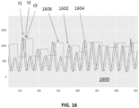
- the identification of the local extremum (F3) consists of obtaining at least three return signal values in succession, corresponding to three different positions of the cartridge in the station and noting that the intermediate value is the highest, so that at the time of identification of the local extremum, the test support is no longer opposite the position sensor.
- scrolling may be rotation of the cartridge.
- the housing includes an injector, configured to inject urine onto the test medium which is identified as being placed in position by the position sensor.
- the station may include a drive actuator, for example a stepper, to drive the cartridge in movement.
- a signal value may be obtained at each step.
- the present description also covers a urine analysis device comprising a station (as described in the various aspects above) and a cartridge.
- the cartridge is then configured to be at least partially received in the annular housing of the housing.
- Each test support is integral with the cartridge and is configured to be able to be selectively positioned in front of the position sensor, the injector and the analyzer.
- the test support is a test strip.
- the present description also covers a kit comprising this station and a cartridge or a plurality of cartridges (cartridges with different types of test supports).
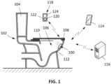
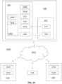
- FIG. 1 schematically illustrates a urine analysis device 100 mounted on a toilet 102.
- the toilet 102 comprises a water tank 104, a bowl 106, a seat 108 and a cover 110.
- the urine analysis device 100 is arranged on an internal wall 112 of the toilet bowl 106.
- the urine analysis device 100 is entirely received in the toilet bowl, which allows it to be discreet.
- the urine analysis device 100 can be positioned in the path of a urine stream secreted by a user.
- the urine analysis device 100 receives a urine stream when a user urinates while sitting in the toilet.
- the position of the urine analysis device is then suitable for any type of user, male or female, regardless of age. The user can then urinate in the toilet without worrying about the position of the urine analysis device.
- the urine analysis device 100 can also be positioned in the path of a flush from the cistern 104. The urine analysis device 100 can thus be rinsed when the flush is actuated.
- the urine analysis device 100 is hygienic.
- the urine analysis device 100 can communicate with a mobile terminal 114 (smartphone type) and/or an external server 116.
- the urine analysis device 100 communicates with the mobile terminal 114 (for example directly via Bluetooth such as Bluetooth Low Energy) and the mobile terminal 114 communicates with the server 116 (via a cellular or WiFi connection).
- the urine analysis device 100 can communicate directly with the server 116 via a cellular network.
- an external activator 118 may be provided.
- the external activator 118 may include a button 120 and/or a biometric sensor 122.
- a screen 124 may be installed on the external activator 118 to display the data obtained by the urine analysis device 100. The latter and the external activator 118 communicate wirelessly.
- the urine device 100 comprises a station 200 and a cartridge 202, removably mounted in the station 200.
- the station 200 comprises in particular a housing 204 which is, according to a particular embodiment, formed as an assembly of two half-shells: a front shell 206 and a rear shell 208.
- the front shell and the rear shell form a joint 210 of the housing, in a plane normal to the axis A.
- the assembly of the urine analysis device is facilitated when the housing is made up of the front shell and the rear shell.
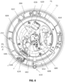
- the housing 204 contains a test assembly (not visible on the Figure 2 but visible on the Figure 6 ). The test assembly is intended to analyze the urine being received in the urine analysis device 100.
- the station 200 further comprises an annular housing 212, inside the housing 204, arranged around an axis of rotation A.
- the annular housing 212 is configured to at least partially receive the cartridge 202 mounted for rotation around the axis of rotation A (once in position in the annular housing 212).
- the cartridge 202 comprises a plurality of test supports integrating a reagent, for example a dry reagent arranged along a circle or an arc of a circle around the axis of rotation A.
- the test supports are test strips.
- the annular housing 212 may be partially delimited, with functional clearance, by an internal cover 214, mounted for example with the rear shell 208, to protect components of the test assembly.
- the internal cover 214 may comprise an outer radial portion, to protect the components radially external to the annular housing 212 and an inner radial portion, to protect the components radially internal to the annular housing 212.
- the annular housing 212 typically extends 360° and forms a groove configured to partially receive the cartridge 202.
- the phrase “radially internal to the annular housing” means closer to the axis of rotation A than the annular housing is to the axis of rotation A.
- the phrase “radially external to the annular housing” means further from the axis of rotation A than the annular housing is from the axis of rotation A.
- the annular housing 212 is accessible for example by detaching the front shell 206 from the rear shell 208.
- the front shell 206 and rear shell 208 can be screwed to each other using a thread 216.
- the station 200 in particular the housing 204, further comprises a collection orifice 218, positioned for example on the rear shell 208 on the Figure 2 .
- the collection port 218 can receive urine flowing by gravity onto the outer surface of the housing 204. More details on this collection port 218 will be given later.
- the housing 204 is arranged in the toilet bowl 106 in a removable manner.
- the analysis device 100 can then be removed or repositioned in the toilet.
- the urine analysis device 100 or the housing 204 can be removed to recharge a battery or to change the cartridge 202.
- the housing 204 is arranged on the internal wall 112 of the toilet.
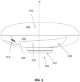
- the housing 204 is positioned by a fixing element 300, one embodiment of which is visible in particular on the Figure 3 .
- the attachment element 300 may include magnets 302 and/or an adhesive/suction surface that may cooperate. This configuration allows the housing to be easily removed or repositioned in the toilet.
- the urine analysis device 100 includes a hook secured to one end of the housing 204 and configured to attach at the other end to a rim of the bowl 106 (under the seat 108 for example).
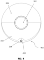
- the station 200 in particular the housing 204, further comprises a drain port 310, positioned on the rear shell 208 on the Figure 3
- the collection orifice 218 can receive the urine flowing by gravity onto the outer surface of the housing 204 and the drain orifice 310 makes it possible to drain the various fluids captured by the device 100. More details on this drain orifice 310 will be given later.
- the housing 204 has an external shape of a circular pebble.
- the housing has a flattened spheroid shape.
- the axis of rotation A is the median axis of the housing.
- the housing has a front face 304 and a rear face 306, substantially normal to the axis A.
- the front face 304 typically comprises the external surface of the front shell 206 and the rear face 306 notably comprises the external surface of the rear shell 208.
- urine can be collected directly from the faces 304, 306 of the housing.
- the housing 204 serves as a urine collector.
- the front face 304 is oriented towards the inside of the bowl 106.
- the front face 304 is then intended to receive urine when the user urinates while sitting on the toilet.
- the rear face 306 is oriented facing the inner wall 112 of the bowl 106.
- the front face 304 and the rear face 306 are connected by curved edges 308.
- the outer surface of the housing 204 consisting of the front face 304, the rear face 306 and the curved edges 308, is defined by curved lines, forming a generally convex object.
- the housing is for example devoid of edges. Urine can run over the entire outer surface of the housing without coming loose. of the case or form air bubbles, which may compromise a urine analysis.
- the request PCT/EP2021/055377 describes in detail the shape of the housing 204 to allow efficient capture of urine.
- the housing 204 has a diameter, measured in the direction normal to the axis A, of between 50 mm and 150 mm, for example close to 100 mm.
- the housing 204 also has a thickness, measured in the direction of the axis A, of between 15 mm and 50 mm, for example close to 30 mm.
- the housing is sufficiently compact to be entirely received in the toilet bowl.
- the urine analysis device is discreet.
- the housing is sufficiently extended to systematically come into contact with urine being received in the bowl. The user can then urinate in the toilet without worrying about the urine analysis device, or failing that, aim roughly.
- the housing is made of a hydrophilic material.
- the housing may be one of: a ceramic, a polyamide (PA), a silicone, or a hydrophilic polymer.
- PA polyamide
- the outer surface of the housing may also be treated with a hydrophilic surface treatment, for example, acuWet ® from Aculon, a hydrophilic polymer, or Pebax ® from Arkema.
- the front shell 206 and the rear shell 208 are assembled to maintain the outer surface of the housing defined by curved lines. Then, the joint 210 between the front shell 206 and the rear shell 208 allows urine flow between the front face and the rear face. The impact of the joint on urine flow over the housing is minimized.
- the front shell 28 and the rear shell 30 can be assembled by gluing, clipping, magnetization, bayonet or ultrasonic welding.
- other fastening means can be used to assemble the front shell and the rear shell.
- an internal portion of the front shell has a thread.
- the thread of the front shell is intended to cooperate with a tapping of the rear shell, or vice versa.
- the housing can thus easily be disassembled to access the test assembly inside the housing.
- a gasket may be present at the joint 210 between the front shell and the rear shell.
- the housing is waterproof.
- the interior of the housing 204 is impervious to urine, water from the water tank 104 or the bowl 106, and any other type of contaminant. Only collection and drain ports connect the exterior and interior of the housing, as described in more detail later.
- the front shell 206 or the rear shell 208 includes a removable cover allowing the cartridge 202 to be replaced. Rather than disassembling the front shell 206 to access the annular housing 212, it is then sufficient to remove the removable cover.
- the removable cover may be attached to the rear shell 208 by clipping, screwing, or by a bayonet mechanism. Of course, other attachment means may be used to attach the removable cover to the rear shell 208. Alternatively, in another example, the removable cover could be attached to the front shell 206.
- the removable cover is arranged in a sealed manner.
- a joint between the removable cover and the rear shell 208 may include a seal.
- the interior of the housing 204 thus remains impervious to urine, water from the water tank 104 or the bowl 106, and any other type of contaminant.
- the removable cover is formed by the front shell 206 of the housing 204.
- the removable cover can then be removed by unscrewing the front shell 28 from the rear shell 30.
- the housing 204 has fewer joints that can become dirty and/or infiltrated by toilet water.
- the housing 204 has a collection orifice 218, already presented in relation to the Figure 2 .
- the collection orifice 218 can receive urine flowing by gravity onto the outer surface of the housing. Urine is collected directly from the faces 305, 306 of the housing.
- the collection port 218 is located on a lower end 402 of the housing 204.
- the lower end 404 is oriented toward the bottom of the bowl 106 when the housing 204 is positioned in the toilet bowl 106. This position corresponds to a normal position of use. This position allows collection of urine flowing by gravity over the majority of the exterior surface of the housing.
- a distance D separating the collection orifice 218 from a lower edge 404 of the housing is less than 40 mm, for example less than 20 mm.
- the collection orifice 218 is arranged a few millimeters above the lower edge of the housing.
- the collection orifice may be on the lower edge 404.
- the collection orifice 218 is a circular opening, for example with a diameter of between 0.3 mm and 2 mm.
- the diameter of the collection orifice may be chosen to maximize the volume of urine collected from the outer surface of the housing.
- the housing 204 has a drain orifice 310, already presented in relation to the Figure 4
- the drain port 310 allows the urine analysis device 100 to be purged of excess urine.
- the drain port 310 is separate from the collection port 218.
- the drain port 310 is also located on the lower end 404 of the housing 204, adjacent to the collection port 218.
- the drain port 310 is also a circular opening.
- the drain port 310 has a diameter of between 0.3 mm and 2 mm. In the normal position of use, the drain port 310 can be located above the collection port 218 without cross-contamination.
- the drain port 310 may also be remote from the collection port 32.
- the position of the drain port 310 may be chosen to facilitate access to the drain port by the test assembly 24.
- the drain port can be the same as the collection port.
- a single port limits the number of openings into the housing. This reduces the risk of introducing contaminants or elements that could clog the test assembly.
- the collection port 218 and/or the drain port 310 may be equipped with a metal mesh filter.
- the average mesh size of the filter is, for example, 20 microns. The filter prevents the introduction of contaminants or elements that could clog the test assembly, and filters the urine received in the collection port.
- the collection port 218 and the drain port 310 are located on the rear face 306 of the housing (on the rear shell 208).
- the collection port 218 and the drain port 310 face the interior wall of the bowl when the urine analysis device 100 is positioned in the toilet. This position makes it possible to mask the collection port and the drain port by the front face of the housing. Also, this position makes it possible to prevent the introduction of contaminants or elements likely to obstruct the test assembly.
- the housing 204 is not limited to the embodiments described above with regard to the figures, but is, on the contrary, capable of numerous variants accessible to those skilled in the art.
- the box can take any geometric shape defined by curved lines.
- the box can be shaped like a diamond or an inverted drop.
- the box then has a point on the bottom to guide the urine towards the collection hole.
- the collection port and the drain port can be on the front of the box. This allows urine flowing down the front to reach the collection port more directly.
- the collection orifice and the drainage orifice may be located on a positive relief, in particular a projection, or a negative relief, in particular a gutter or a recess.
- the relief may be of any geometry allowing the channeling of urine running down the housing and route it to the collection port without detaching from the housing or forming air bubbles.
- the collection orifice 218 is arranged on the front face 304, while the drain orifice 310 is located on the rear face 306.
- Test set (injector and analyzer)
- test strips for example colorimetric strips or lateral flow strips
- the strips are also referred to herein as “test strips” or more simply “strip”.
- the test assembly includes in particular an injector and an analyzer (for example an optical analyzer).
- the cartridge 202 is rotated in the housing 204 by a drive actuator, positioned in the housing 204, so that the test strips can pass successively in front of the injector and the analyzer.
- the test assembly also includes a position sensor, for identifying a position of the strips in the housing. The position sensor can make it possible to locally identify the position of the strip (and not necessarily in absolute terms).
- the injector, the analyzer and/or the position sensor can be positioned in the housing 204 at the same angular location or at different angular positions, either radially internal or external to the annular housing 212.
- the injector makes it possible to inject a controlled volume of urine onto a strip when said strip is in an injection zone ZI of the annular housing 212.
- the injection zone ZI corresponds to an angular window (around the axis of rotation) of the annular housing 212 within which the injector is able to inject the urine onto the strip.
- the analyzer makes it possible to analyze a strip when said strip is in an analysis zone ZA of the annular housing 212.
- the analysis zone corresponds to a window or angular range (around the axis of rotation) within which the analyzer is able to take measurements on the strip.
- the position sensor makes it possible to obtain a position of the cartridge or strip when a marker associated with it is located in a control zone ZC.
- the control zone ZC corresponds to a window or angular range (around the axis of rotation) within which the position sensor is able to obtain a position of the cartridge or strip.
- the position measurement obtained by the position sensor is used to control the drive motor (feedback loop).
- the position sensor can allow the station to know that a strip is indeed in the control zone, but not necessarily to know which strip it is.
- the position sensor coupled with a counting of the displacement from a zero (described later), can make it possible to know which strip exactly is located in the control zone.
- the injection zone ZI, the analysis zone ZA and/or the control zone ZC may be merged, partially merged or distinct.
- the analyzer can detect a change in color of the test medium, which can be a strip (colorimetric analysis).
- the analyzer can then be an optical analyzer, with a light source and an optical sensor.
- FIG. 5 illustrates an exploded view of one embodiment of the cartridge 202.
- the cartridge 202 incorporates test supports intended to receive urine when the cartridge 202 is mounted in the station 200 and, in particular, in the annular housing 212.
- the test support comprises a reagent which reacts once in contact with the urine.
- the test supports may be test strips 501 (for the remainder of the description we will speak of test strips).
- the cartridge 202 comprises a rotating support 500, configured to be rotated by the station 200. In normal use of the cartridge 202 and the urine analysis device 100, the strips 501 remain mounted in the rotating support 500 and do not move relative to the latter. The strips are therefore attached and secured to the rotating support 500. In particular, the strips 501 are not wound in an unrollable manner on the rotating support 500 for use: they are therefore not unrolled during use.
- the rotating support 500 is of hollow cylindrical shape extending annularly around an axis which is, when the cartridge 202 is mounted in the station 200, the median axis A of the housing 204 (for convenience of language, a single axis A will be used to describe the different elements, called the axis of rotation A).
- the rotating support is generally symmetrical in revolution around the axis of rotation A. The rotating support 500 makes it possible to store a large number of test strips 501 while being sufficiently compact to be arranged inside the housing 204.
- the cartridge 202 and the rotating support 500 as illustrated in the figures extend over a complete revolution and can perform a complete revolution in the station 200.
- a cartridge 202 which extends over a portion of a revolution (for example less than 180° or 90°) and which only rotates a portion of a revolution (for example less than 270°).
- the number of strips is typically lower than for the urine analysis device illustrated in the figures.
- the strips are arranged in a circle or a portion of a circle, for example at a radial end of the rotating support 500 to maximize their number (the larger the radius, the larger the perimeter for installing strips).
- the circular positioning ensures that the strips 501 are all at the same distance from the rotation axis A and, therefore, from the injector or analyzer (in particular an optical sensor of the analyzer, which will be described later). This also ensures that the measurement protocol for each strip is identical.
- the strips 501 may generally be arranged in a circular or arcuate arrangement.
- the strips 501 can therefore be equidistant from the axis of rotation A.
- each of the strips 501 can be a small, thin, and narrow strip which extends in its longitudinal direction parallel to the axis A.
- the strips 501 are arranged parallel to each other.
- the cartridge 202 In its shape and function, the cartridge 202 resembles a barrel. In an exemplary embodiment, the cartridge substantially occupies the annular volume provided by the annular housing 212. A small functional clearance is provided to allow the cartridge to rotate without rubbing against the walls of the annular housing 212.
- an outer diameter of the rotating support 500 may be between 30 mm and 130 mm, preferably approximately 60 mm.
- a height of the rotating support, measured in the direction of the axis A, may be between 12 mm and 40 mm, preferably approximately 14 mm.
- a ratio between the diameter of the rotating support and the diameter of the housing 204 may be greater than or equal to 0.3, preferably greater than or equal to 0.5. This provides a solution of very good compactness with regard to the large number of test strips available.
- the rotary support 500 comprises an annular portion 502 and a cylindrical portion 504, extending from an outer radial end of the annular portion 502.
- the cylindrical portion 504 typically extends on only one side of the annular portion 502 and is configured to be inserted into the annular housing 212 of the housing 204.
- the strips 501 are positioned along the cylindrical portion 504 (oriented parallel to the axis of rotation A), in order to be able to scroll selectively and/or successively in front of the injector and the analyzer.
- the annular portion 502, for its part, remains outside the annular housing 212 and in particular makes it possible to stiffen the cylindrical portion 504 and/or to allow the cartridge 202 to rotate.
- the annular portion 502 may further comprise a mechanical coupler 506 configured to engage with a mechanical coupler of the station 200, for example a female fixing sleeve configured to engage with a shaft driven in rotation by the motor or a male fixing shaft configured to engage a female sleeve driven in rotation by the motor.
- a mechanical coupler 506 configured to engage with a mechanical coupler of the station 200, for example a female fixing sleeve configured to engage with a shaft driven in rotation by the motor or a male fixing shaft configured to engage a female sleeve driven in rotation by the motor.
- an axial drive pinion 602 is provided (visible in Figure 6 ) at the reducer output, and the female portion is formed by the hub 506 of the rotary support 500.
- the mechanical coupler 506 is arranged on the rotation axis A of the rotary support 500.
- the annular portion 502 may be devoid of the female sleeve 602.
- the annular portion 502 could be mounted by any type of pivoting connection relative to the housing 204.
- the annular portion 502, with the exception of the mechanical coupler 506, when it is through, at the axis A, may be similar to a disc.
- the female sleeve and the hub may be reversed.
- the cartridge 202 comprises a separator 508 having housings 510 for receiving the strips 501.
- the housings 510 and the strips 501 have similar dimensions which will be given at the end of the description.
- the separator 508 is for example a flexible part, in particular made of elastomer, in the form of a strip or ribbon intended to be wound in the rotating support 500.
- the separator 508 extends along a longitudinal direction and can be wound against an internal wall of the annular portion 504 of the rotating support 500.
- the separator 508 comprises a first face comprising a plurality of housings 510 each receiving one or more test strips 501. The first face can be covered by a seal to protect the strips when not in use.
- the separator 508 comprises a second face comprising, opposite each housing 510, at least one through-orifice 512 (for example two, as illustrated in the transparent view of the annular portion 504).
- the housings 510 are thus sealed. Thanks to the flexible separator 508, the insertion of the test strips 501 into the housings 510 can be done on a flat surface, which simplifies assembly. Once the separator 508 is installed, the housings 510 extend parallel to the direction of rotation A.
- the cylindrical portion 504 is transparent, or else comprises transparent zones, in particular opposite the housings 510.
- the cylindrical portion 504 is in contact with the separator 508, in particular the second face of the separator 508.
- the light can pass through the cylindrical portion 504, passing through the through-orifice 512 to analyze the test strips.
- the cylindrical portion 504 may in particular be made of polycarbonate. Indeed, polycarbonate has good light transmission properties, while remaining relatively inexpensive and compatible with an injection molding process.
- the annular portion 502 of the rotary support 500 forms a base for carrying the separator 508.
- the cylindrical portion 504 receives the separator 508.
- the separator 508 is blocked in translation in the direction A by contact with the annular portion 502.
- an annular rim extending from one end of the cylindrical portion 504 and radially inwards makes it possible to block the translation in the other direction of the direction A.
- the rotary support 500 and more particularly the cylindrical portion 504, further comprises a through purge opening 514, to allow the injector to pass through the cartridge 202 and the annular housing 212 and to join an evacuation circuit of the station.
- the separator 508 does not cover the purge opening 514. This circuit will be described in detail later.
- the cartridge 202 further comprises an identifier 516, shown in the Figure 5 by an RFID chip.
- the identifier 516 allows the station 200 to know which cartridge 202 has been inserted.
- the identification 516 is typically a passive RFID tag.
- the rotating support 500 could be a washer, with an axis coincident with the median axis A of the housing.
- the washer then extends radially, along a plane substantially normal to the median axis A of the housing.
- the test strips can then be stored on one face of the washer, normal to the axis A.
- Each housing 510 can accommodate a single test strip. All test strips 501 in the housings 510 can be of the same type. By same type, we mean that they are sensitive to the same compounds contained in urine.
- the cartridge 202 is then adapted for a specific analysis.
- test strip 501 received in the housing 510 may be of a different type than the test strip received in the neighboring housing.
- several types of analyses, requiring different types of test strips, may be performed from the same cartridge 202.
- each housing 510 may contain a plurality of test strips 501 of different types. Thus, several types of analyses may be carried out from the same housing.
- each 510 housing is covered and closed by a cover (visible in Figure 12 at reference 511).
- the seal makes it possible to hermetically isolate the test strips 501 received in a housing 510 from the external environment and from neighboring housings.
- the housing 510 becomes accessible for the injection of liquid typically by piercing the seal (for example by the injector 604). Then, before an analysis, the reagents of the test strips are protected from possible contamination.
- the seal can contain urine introduced into the housing 510.
- the seal can take the form of a continuous film. The film is glued to the outer wall of the rotating support to cover the housings 510. This configuration facilitates the installation of the seal 511 on the rotating support 500.
- each housing 510 can be covered by a separate seal.
- This configuration makes it possible to limit the risk of contamination of test strips received in two neighboring housings.
- the test strips can be encapsulated individually. This configuration appears particularly advantageous when the test strips are connected to form a ribbon. Indeed, the ribbon can be assembled in the rotating support without require the addition of an additional seal. Assembly of the urine analysis device 100 is made easier.
- the seal is here made of an inert material.
- the seal may be made of silicone or acrylic.
- the seal is of medical grade, to avoid contamination of the test strips with unwanted products contained in the seal.
- the reagents of the test strips are kept intact before analysis.
- the seal is transparent, a transparency rate preferably being greater than 99%. Then, a colorimetric analysis can be carried out on a test strip through the seal.
- the cartridge 202 is, when placed in the station 200, mechanically coupled to a drive actuator 600 ( figures 6 , 8 And 10 ), via its mechanical coupler 506 and a complementary mechanical coupler 602 of the station 200, to be driven in rotation around the axis A.
- the cartridge 202 can then be selectively positioned to align a test strip facing the injector, referenced 604 or the analyzer, referenced 606.
- the use of the cartridge 202 makes it possible to have a simple mobile assembly with a single axis of rotation. In addition, this configuration reduces the constraints linked to the positioning and arrangement of the injector 604 and the analyzer 606 in the analysis device 100.
- the drive actuator 600 can be offset relative to the axis A and a gear train 608 (which can also act as a reducer) is used to drive the coupler.
- complementary mechanical coupler 602. The complementary mechanical coupler 602 of the station 200 is located on the rotation axis A.
- the drive actuator 600 can drive the cartridge 202 in a clockwise or counterclockwise direction.
- the cartridge can then quickly reach the desired position, following the shortest path. This further reduces the constraints related to the positioning and arrangement of the injector 604 and the analyzer 100.
- the drive actuator 600 is, for example, a drive motor, such as a stepper motor or a DC motor. Alternatively, the drive actuator 600 may involve a hydraulic or other system.
- the collection port 218 is fluidically connected to a collector 610 then a collection pipe 612 then a pump 614, then a delivery pipe 616 then the injector 604.
- the injector 604 is movable in the housing 204, so that the injector can move to inject urine selectively onto a strip or into a drain pipe 618 connected to the drain port 310, depending on the position of the cartridge 202 in the station 200.
- the urine collected by the collection port 218 is set in motion in the fluid circuit thanks to the pump 614.
- the delivery pipe 616 may comprise a flexible portion (not shown in the Figure 6 for example), particularly at its end which connects it to the injector, to accommodate the movement of the injector.
- the injector 604 typically comprises three positions: a withdrawal position PR, an injection position PI and a purge position PP.
- the injector 604 In the withdrawal position PR, the injector 604 does not hinder the rotation of the cartridge 202 in the annular housing 212; in the injection position PI, the injector 604 allows the injection of urine onto a strip positioned in the injection zone ZI; in the purge position PP, the injector 604 is connected to the drain pipe 618.
- the injector 604 is entirely radially internal to the annular housing 212, entirely retracted; in the injection position PI, the injector 604 is partially internal to the annular housing 212 and partially in the annular housing 212; in the purge position, the injector 604 is partially internal to the annular housing 212, partially in the annular housing 212 and partially external to the annular housing 212.
- the cartridge 202 must also be in the purge position, that is to say the purge orifice 514 of the rotating support 500 must be aligned with the injector 604 (radially aligned with a distal injection end of the injector).
- the pump 614 can aspirate urine.
- the pump aspirates, for example, between 5 microliters and 1 mL, preferably approximately 20 microliters.
- the pump can deliver a sufficient volume of urine to the injector 604 to enable a conclusive analysis to be performed.
- a suction flow rate of the pump 614 is selected based on the diameter of the collection orifice.
- the pump can aspirate urine from the collection orifice to the injector without forming air bubbles.
- the pump 614 can also suck air from the collection orifice 218 to eject it via the drain orifice 310. Then, the pump makes it possible to expel urine or water contained in the urine analysis device. Urine collected for an analysis is then protected from possible contamination by water from the toilet or from a previous collection. According to another phase or an alternative embodiment, it can be provided that the pump 614 can suck water when activating the flushing of the toilet to evacuate the urine contained in the urine analysis device.
- the pump 614 may be of various possible types.
- the pump 614 may be a miniaturized peristaltic pump.
- the pump 614 may be a miniaturized pneumatic pump system as detailed below. In the case where the pump 614 is a miniaturized pneumatic pump, this pneumatic system is configured to create a vacuum to draw urine from the collection port 218, then a positive pressure to push the urine towards the injector 604 and the purge channel.
- the pump of the pneumatic system can here be a rotary type pump, the direction of rotation respectively and selectively providing a vacuum or an overpressure.
- the pump of the pneumatic system can also be a piezoelectric type pump.
- the injector When urine is aspirated, the injector may be provided in the purge position to vent air until urine is pre-charged.
- the presented solution allows to precisely control the volume delivered to the urine analysis device.
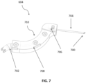
- the injector 604 comprises a distal end, called the injection end, 700 and a proximal end 702, called the connection end, which is typically configured to be connected to the delivery pipe 616 (in particular the flexible portion of the delivery pipe, which is not shown in the Figure 6 , so that the proximal end 702 opens into the open air).
- the injector 604 may comprise a needle 704 and the distal end 700 may then be the end of the needle 704.
- the injector 604 is movable in translation in a translation direction DT relative to the housing 204.
- a displacement actuator 620 is provided in the housing 204 to move the injector.
- the injector 604 is positioned, in the housing 204, radially inside the annular housing 212.
- the displacement actuator 620 is also positioned radially inside the annular housing 212.
- the acceptable angular position for the injection (called the injection window) is quite small.
- the window is constrained by the inclination between a radial direction (according to a radius of the circle defined by the housings) and a depth of the housing. Therefore, the number of drive motor steps to be activated so that the housing is correctly positioned during injection is low.
- the injector 604 has a curved shape, so that the translation axis at which the injector 604 is driven in translation is offset relative to the translation axis of the distal end 700. It is understood here that a portion of the injector which channels the fluid is curved (and that the path of the fluid substantially follows this curve).
- first axis T1 which is the axis at which the injector 604 receives the translational movement
- second axis T2 which is that of the displacement of the distal end 700
- the injector 604 can also be defined by the fact that it is located radially inside the annular housing 212 and that the distal end 700 moves in translation in a radial direction or substantially in a radial direction (i.e. radial to within a few degrees, for example 10°, preferably 5° and even 2° on either side of said radial direction, or even 1°). This radial movement is allowed by the curved shape (in projection in a plane orthogonal to the axis of rotation A) of the injector 604.
- the curved shape of the injector 604 makes it possible to bypass the mechanical coupler 602 located at the axis of rotation A while having the second axis T2 which is merged with a radius of the circle defined by the housings.
- the distal end 700 moves along a radial direction, and therefore orthogonal to the cover 511, to the strip 501 and/or to the bottom of the housing 510. Consequently, the first axis T1 does not pass through the mechanical coupler 602 but the second axis T2 passes through the mechanical coupler 602.
- the injector 604 does not interfere with a cylinder of radius R4 centered on the axis A. This leaves free an axial space where the hub of the support 500 of the cartridge is housed.
- the first axis T1 is offset from the axis T2 (in a plane orthogonal to the axis of rotation) by an offset distance equal to minus the distance of the radius R4 (R4 plus the thickness of a cover, plus at least one functional clearance).
- the radius R4 can be at least equal to 3 mm.
- R4 can be at least equal to 5 mm.
- the offset distance is typically between 5 and 15 mm, or even between 5 and 10 mm.
- the second axis T2 is advantageously radial or substantially radial (plus or minus 2°, or even 5°, or even 10° on either side of a radial direction).
- the curvature of the injector 604 may comprise two successive inverted bends 706, 708 (see Figure 7 in particular).
- the injector 604 comprises an intermediate portion 710.
- the two elbows 706, 708 may be formed in the intermediate portion 710.
- the two elbows 706, 708 are rounded, in order to disturb the movement of the fluid as little as possible.
- the proximal elbow 708 (closest to the proximal end 702) may have a shape complementary to the mechanical coupler 604 of the station 200 to allow the distal end 700 to have a maximum translation amplitude.
- the distal elbow 706 (closest to the distal end 700) may have a smaller radius of curvature, so that the intermediate portion is mainly constituted by the proximal elbow 708.
- the distal elbow 708 therefore has the essential function of allowing the injector 604 to be inserted into the housing 204, bypassing the mechanical coupler 602 and the proximal elbow 706 has the function of realigning the injector 604 (in particular to realign the needle 704) in a radial or substantially radial direction.
- it is the needle itself that is curved.
- the injector 604 is rigid.
- rigid it is meant that it does not deform during normal use of the device.
- the intermediate portion 710 is rigid.
- the injector 604 can be less than 2mm from the mechanical coupler 604 (closest distance).
- the distal end 700 of the injector 604 is located radially external to the annular housing 212.
- the purge opening 514 can also serve as a zero marker for obtaining the position of the cartridge 202.
- the curvature of the injector 604 is only in a plane orthogonal to the axis of rotation A.
- the injector may have a curvature that creates an offset along the axis of rotation A, such that the distal end 700 is higher or lower (along the axis of rotation A) than the proximal end 702. This allows for level differences in the device 100 to be accommodated.
- the displacement actuator 620 mounted in the housing 204, is provided to generate the movement.
- the figure 8 illustrates an embodiment using a screw-nut connection.
- the displacement actuator 620 may be a displacement motor 620, for example an electric motor, which drives a rod 622 in rotation.
- the rod 622 mechanically cooperates with a nut 800 secured to the injector 604, so that the rotational movement of the rod around the first axis T1 is transformed into translation of the nut 800 at the level of the first axis T1.
- the rod 622 and the nut 800 each comprise a thread which cooperates with each other.
- the size of the displacement actuator 620, the rod 622 and the other components making it possible to produce a functional injector are offset in a free zone of the housing 204, next to the mechanical coupler 604 of the station 200, while the proximal end 700 of the injector 604 can move along the second axis T2, which is a radial or axial direction. substantially radial.
- the 800 nut is called a captive nut, in the sense that it cannot turn on itself.
- the screw-nut connection allows for good conversion of movements, without skipping steps, lag between the setpoint and the result, or even without loss of connection in the event of the 200 station falling.
- friction and the need for lubrication are low. For example, lubrication during assembly is sufficient.
- the 800 nut can be made as a threaded insert or by tapping a hole.
- the displacement actuator 620 may be a linear motor, or even a linear actuator (cylinder, etc.), which produces a translational movement directly.
- the injector 604 may be secured to a guide 802 (or slide) in translation at the level of the first axis T1.
- the guide 802 may comprise a circular orifice which cooperates with a fixed rod 804 secured to the housing 204.
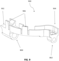
- the injector 604 can be mounted on a carriage 900, shown alone in figure 9 and visible in the box in Figure 10 .
- the carriage 900 has a curved shape that can accommodate the injector 604.
- the force absorption of the displacement actuator 620 can be done on the carriage 900 rather than on the injector 604 directly, to protect the latter from any mechanical stress. Indeed, the offset due to the curvature of the injector 604 and the reaction force of the seal 511 when it is pierced by the injector 604 can create a parasitic torque.
- the carriage 900 allows greater solidity of the system. For example, at a proximal end 902 of the carriage 900 is the nut 800 which couples with the rod 622.
- the guide 802 At a distal end 904 is the guide 802, in the form of a circular orifice.
- the offset between the two holes of the nut 800 and the guide 802 may correspond to the offset between the first translation axis T1 and the second translation axis T2 (in a plane orthogonal to the rotation axis A).
- the carriage 900 may comprise holding clips 906 to hold the injector 604 in position.
- the displacement actuator 620 makes it possible to move the injector 604 into the three positions mentioned above: the withdrawal position PR, the injection position PI, the purge position PP. Actuation of the displacement actuator 620 makes it possible to carry out these movements between the three positions PPI, PI, PP.
- the distal end 700 may also be configured to pierce the seal 511 of the cartridge 202.
- a bevel may be provided to facilitate insertion.
- the needle 704 may have a diameter of approximately 0.5 mm.
- the proximal end 702 and the intermediate portion 710 may be made of a single piece (for example, produced by 3D printing), and the needle 704 is inserted into the intermediate portion which includes an orifice provided for this purpose.
- the needle 704 may be made of metal.
- the injection zone ZI which corresponds to the window or angular range (around the axis of rotation) for positioning a strip 501 for a good injection of urine by the injector 604, typically comprises a few degrees maximum (less than 5°, or even less than 2°).
- this injection window corresponds to a few steps (the number depending on the drive motor 600 itself and the gear train 608).
- the injector 604 can inject a controlled volume of urine onto a test strip, for example between 2.5 microliters and 3.5 microliters.
- the injector injects a sufficient volume of urine onto a test strip to perform a conclusive analysis without risking urine overflow from the housing.
- the injector 604 can inject a controlled volume of urine onto the test strip 56 in two steps.
- the injector 604 can inject between 2.5 microliters and 3.5 microliters twice. This solution allows for taking into account a reaction time and migration of urine onto the 501 test strip.
- a position sensor 624 is provided in the housing 204 to obtain the position of the cartridge 202 and/or the strips 501 relative to the housing 204 and more precisely relative to the injector 604 and/or the analyzer 1200. This makes it possible to improve the precision since the displacement actuator 620 can be controlled by position instructions using the data from the position sensor 624 (feedback loop).
- the injector 604 In order for the injector 604 to be able to inject the urine correctly onto the chosen strip 501, it is important to know the position of the strips 501 in the annular housing 212. In particular, due to the structure of the cartridge 202, assembly inaccuracies are possible, so that the strips 501 are not regularly positioned (small offsets, but given the distances involved, which can generate poor analyses).
- the analysis station 200 therefore comprises a position sensor 624 (visible in figures 6 Or 11 ).
- the position sensor 624 can be positioned at least partially, in the housing 204, radially outside the annular housing 212.
- the position sensor 624 makes it possible to identify the position of a marker of the cartridge 202 when said marker is located in the control zone ZC.
- the injector 604 is configured to inject urine into an injection zone ZI of the annular housing 212 and the position sensor 624 is configured to obtain the position of a marker associated with the strip 501 in a control zone ZC of the annular housing 212.
- the injection zone ZI and the control zone ZC are the same or close together.
- the position sensor 624 makes it possible to measure the position of a marker associated with a strip 501 when said marker is positioned in the injection zone ZI or in a zone close to the injection zone ZI (the measurement is made on this marker, and not by deduction from a measurement on a marker outside or at a distance from the injection zone ZI). This means that the position sensor 624 makes it possible to know precisely the position of a strip of interest 501 in the injection zone ZI and therefore to inject the urine correctly onto the strip of interest 501.
- the inaccuracies in the position of the strips 501 due to the positioning of the strips in the separator 508 and to the separator 508 itself in the cartridge 202 (which is flexible), are generally low from one housing to another. Consequently, by measuring the position of a marker in an area close to the injection zone ZI and therefore close to the strip 501 of interest, we obtain fairly precise data as to the position of the strip 501 of interest in this injection zone ZI.
- proximity zone it is meant less than 30° on either side of the injection zone, or even less than 20°, or even less than 10°, or even less than 5°.
- the closer the position sensor 624 measures a marker to the strip 501 the better the accuracy for this strip 501.
- the position sensor 624 measures the position of a marker from the injection zone ZI the more the positioning inaccuracies can accumulate, so that the strip of interest may in reality not be correctly located in the injection zone ZI.
- the marker is the strip 501 directly, which maximizes accuracy. A detailed description will be given later.
- the marker is a locatable element located on the cylindrical portion 504 of the cartridge 202 or on the separator 508.
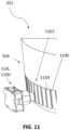
- the position sensor 624 is a mechanical sensor, for example in the form of a follower 1100, mounted in the housing 204, which cooperates with a lobed cam 1102 of the cartridge 202 (of the cylindrical portion 504 for example).
- the marker is then the top 1104 or the bottom 1106 of the lobed cam which is closest to a strip.
- the position of the strip can be known and the latter can be correctly positioned in the injection zone ZI.
- the position sensor 624 may include an electromagnetic sensor, such as a Hall effect sensor, and the marker may be a magnetic element on the cartridge.
- a magnetic element may be mounted on the rotatable holder opposite or adjacent to each housing 510.
- the position sensor 624 is radially aligned (once projected in a plane orthogonal to the axis of rotation) with the distal end of the injector (same angular location around the axis of rotation A therefore), but offset along the axis of rotation. In this way, the measurement obtained is relevant for the injection.
- the position sensor 624 is an optical sensor that locates the marker by analyzing a received light signal. More specifically, the position sensor 624 may be the analyzer 606 itself. This allows for gains in compactness and accuracy, since the marker is very close to the strip (or is even the strip).
- FIG. 12 illustrates in detail an embodiment of the analyzer 606, referenced 1200 herein.
- the analyzer 606 can perform the colorimetric analysis on the test strips.
- “Colorimetric analysis” means a measurement of absorbance or fluorescence under predetermined illumination, in transmission or reflection.
- the analyzer 606 can then determine one or more analysis results.
- the analyzer 606 may be an optical analyzer 1200, comprising at least one light source 1202 (for example one or more light-emitting diodes), 1204 and a sensor 1206 (for example a CCD, “Charged Coupled Device”, or CMOS (“ Complementary Metal Oxide Semiconductor ”) photodiode.
- the light source may comprise two separate sources 1202, 1204 (for example two different wavelengths)
- the analyzer 1200 is typically located on either side of the annular housing 212, so that the light emitted by the light source 1202, 1204 can pass through the transparent cylindrical portion 504, then the orifices 512 of the splitter, then the strip, to finally reach the optical sensor 1206.
- An optical splitter 1208 makes it possible to guide the two light sources 1202, 1204 to avoid light leakage from one optical path to the other.
- the 1200 analyzer works in the analysis zone ZA.
- the analyzer 1200 includes multiple LEDs of wavelength specific to the different reagents contained in different types of test strips.
- the urine analysis device can perform different analyses accurately.
- each light source 1202, 1204 may each comprise a white LED and an ultraviolet LED.
- a vertical separator (not visible in the Figure 12 ) can be provided to prevent activation of the white LED from exciting the ultraviolet LED.
- the analyzer 1200 may include a single LED.
- the LED may be white.
- the LED may cover the entire visible spectrum. This configuration reduces the complexity of the analyzer.
- the 1200 analyzer may also include a collimator.
- the collimator directs the illumination of the LED(s) toward the test strip.
- the sensor 1208 can measure the absorbance or fluorescence of the test strip reagent, in particular by transmission or reflection, to establish the analysis result(s).
- the 1208 sensor can be topped with a filter.
- the filter increases the sensitivity of the optical sensor to specific wavelengths. The accuracy of an analysis is then very satisfactory.
- the analyzer 1200 is here arranged on either side of the annular housing 212 (and therefore on either side of the cylindrical portion 504 when the cartridge 202 is inserted into the station).
- a first part of the analyzer 1200 e.g., the light source 1202, 1204
- a second part of the analyzer 1200 e.g., the optical sensor 1206
- the analyzer 1200 operates by transmitting light from the first part to the second part.
- the first part comprises the light source 1202, 1204, for example in the form of a pair of LEDs 1202, 1204.
- the light is guided through the orifices 512 to illuminate the test strips 501.
- a first LED 1202 of the pair may be white in color to cover the entire visible spectrum and determine color changes of the test strip 501.
- a second LED 1204 of the pair may be monochromatic, for example ultraviolet, to excite fluorophores and allow observation of their emission wavelength.
- the second part includes the optical sensor 1206.
- the optical sensor 1206 is of the spectral type. It comprises several photodiodes topped with filters to measure the intensity of light at different wavelengths distributed in the visible range.
- the sensor 1206 is compatible with optical measurements by absorbance and fluorescence.
- the sensor 1206 may be used for different types of test strips.
- the test strip 501 is of the immunochromatographic type and has a test region and a control region aligned respectively with the orifices 512, the color change of which allows a result to be obtained.
- the test strip 501 may be a colorimetric strip and have two separate test regions (for example, to simultaneously test the pH and the specific gravity of urine) aligned respectively with the orifices 512.
- the analyzer 1200 may be arranged on a linear motor. In this way, the analyzer can move closer to a test strip to perform a more accurate analysis.
- the analysis zone ZA of the analyzer 1200 is merged with the injection zone ZI of the injector 604.
- the drive actuator 600 does not need to be activated and rotate the cartridge 202 between the injection of urine by the injector 604 and the analysis of the strip 501 by the analyzer 1200.
- the injector 604 and the analyzer 606, 1200 are arranged to work angularly at the same location and can interact with the same strip (without rotation of the cartridge 202). The advantages are multiple.
- the analysis can start just before (for example at most two seconds or at most one second), at the same time or just after the injection, so that the kinetics of the chemical reaction (for example the speed of color change) of the strip 501 once in contact with the urine can be observed.
- a good position for the injection means a good position for the analysis.
- the optical sensor 1206 can be offset, along the axis of rotation A, from the injector 604 (in particular from the needle 704). It is thus possible to obtain a configuration making it possible to inject and analyze the same strip without rotating the cartridge (and therefore without activating the drive actuator 600).
- the analysis zone ZA of the analyzer 1200 is merged with the control zone ZC of the position sensor 624. This makes it possible to ensure that the strip 501 is correctly positioned for measurement by the analyzer 1200 and thus to have a quality measurement.
- the optical sensor 624 may be the analyzer 1200 itself.
- the analysis zone ZA, the injection zone ZI and the control zone ZC are merged. This means that the position sensor 624 determines that a strip 501 is correctly positioned using a marker located in a zone close to said strip 501. Then the injection and the analysis take place without the cartridge 202 being rotated.
- test medium e.g. strip
- the marker for the position sensor 624 is the strip itself. In this way, the position sensor 624 is configured to directly measure the position of a strip relative to the housing 204. This eliminates uncertainties in the positioning of the strip in the separator 508 or uncertainties related to the position of the separator 508 in the rotating support 500.
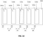
- FIG. 13 schematically illustrates examples of inaccuracies, using a partial view of a separator 508 shown flat and not wound on the rotating support.
- Five housings 510a, 510b, 510c, 510d, 510e are shown, with a respective strip 501a, 501b, 501c, 501d, 501e. Due to the flexibility of the separator 508, when it is put in place, the distance d1, d2, d3, d4 between two housings can vary. Due to the flexibility of the strips and their insertion into the housings, the position e1, e2, e3, e4, e5 of the strips in their housing can also vary.
- a marker positioned on the rotating support 500 does not allow these irregularities to be taken into account and, thus, only gives the position of the strip with which it is associated with these irregularities.
- the position sensor 624 when it directly measures the position of the strip, makes it possible to completely overcome these irregularities.
- the position sensor 624 is an optical sensor, without contact with the cartridge 202.
- the position sensor 624 is the analyzer 1200 itself (the control zone ZC and the analysis zone ZA are therefore merged). This results in compactness and precision, as indicated previously.
- the position sensor 624 (which may be the analyzer 1200 itself, as indicated previously) receives a variation of light which corresponds to light passing through the orifices 512 of the separator 508 and on either side of the strip 501 or passing through the strip 501. Consequently, the detected signal depends directly on the position of the strip 501 in the annular housing 212, independently of the position of the strip 501 relative to the separator 508 or to the rotating support 500. The control of the drive motor 600 can therefore be done independently of the position of the rotating support 500 or of the separator 508.
- Obtaining data directly from the strip also allows the strips to be characterized. For example, strips, depending on their nature, can have different extremes. It is thus possible for the station, using the extreme value and using a table stored in the station, to know the nature of the strip present in the control zone (and therefore in the injection zone and the analysis zone).
- the position sensor 624 makes it possible to know whether a strip is in the control zone (local position) but not to know directly the absolute position of the strip in the cartridge (in other words, to know which strip of the cartridge is in the control zone ZC).
- the ECU can count the number of strips which pass from zero (zero being the through-hole 514, which is easily identifiable by a signal value higher than the others - because the light only passes through air or transparent or almost transparent components).
- the station can identify the strip.
- the table can match, for a given cartridge model, the nature of the strip and a strip number (the numbering being unique in each cartridge).
- the identification 516 allows the station 200 to obtain the cartridge model and therefore to know which table is used.
- the device 100 comprises a urine presence sensor.
- the urine presence sensor may be in proximity to the collection port.
- the urine presence sensor then makes it possible to detect when urine is present in the vicinity of the collection port.
- the urine presence sensor can be a temperature sensor, for example a thermistor.
- the temperature sensor can distinguish between urine and toilet water.
- the temperature sensor can also be used to measure urine temperature.
- Urine temperature can be used to detect periods of fertility, in particular, by comparing it to one or more reference curves. The use of a temperature sensor then makes it possible to reduce the number of components used by the test set to perform an analysis. The complexity and costs associated with manufacturing the urine analysis device are reduced.
- the urine presence sensor can be any type of liquid detector, for example a capacitive or resistive sensor.
- FIG. 14 represents a schematic view of an analysis environment 1400 comprising the urine analysis device and its environment.
- the station 200 is controlled by an electronic control unit ECU 1402.
- the ECU 1402 is inside the housing 204.
- the ECU 1402 makes it possible to control the components of the test assembly to carry out a urine analysis using the test strips 501 and obtain one or more analysis results.
- the ECU 1402 manages the drive actuator 600, the displacement actuator 620, the position sensor 624, the analyzer 1200 and the pump 614.
- the ECU 1402 typically comprises a processor 1404 and a memory 1406 capable of storing instructions that the processor 1404 executes. In particular, the methods described in the description are stored in the form of instruction lines in the memory 1406.
- the station 200 comprises a communication module 1408, typically wireless, for example Bluetooth, WiFi and/or cellular (GSM, 3G, 4G, 5G, 4G-LTE).
- GSM Global System for Mobile communications
- 3G, 4G, 5G, 4G-LTE Global System for Mobile Communications
- a battery 1410 provides power to the various components of the station 200.
- the station 200 may include a reader 1412, for example a contactless proximity reader, such as an RFID reader.
- the mobile terminal 114 comprises in particular a processor 1414 and a memory 1416, which make it possible, for example, to run an application which serves as a user interface for the device 100.
- the server 116 also comprises a processor 1418 and a memory 1420, for processing and storing data generated in particular by the device 100.
- the device 100, the mobile terminal 114 and the server 116 communicate with each other via a telecommunications network 1422.
- the telecommunications network 1422 may be hybrid, comprising a WiFi or Bluetooth network and a cellular network, the roles of which have been explained previously.
- Step E0 consists of maintaining the urine analysis device 100 in a purge position.
- the ECU controls the drive actuator 600 to place the purge opening 514 of the cartridge 202 in the injection zone ZI (i.e. aligned with the injector 604).
- the ECU uses position data obtained by the position sensor 624 which can locate the opening 512 (for example by a stronger light signal because there is no strip between the light source and the photodiode).
- the ECU Before the rotation of the cartridge, the ECU has driven the displacement actuator 620 to put the injector in the withdrawal position PR.
- the ECU drives the displacement actuator 620 so that the injector 604 moves to the purge position PP.
- the device 100 can thus be rinsed of water or residues urine.
- urine or water received from the toilet in the collection pipe 612 can reach the drain port 310.
- Step E1 (“urine collection”), the ECU activates the pump 614 to deliver urine from the collection port 218 to the injector 604.
- the injector 604 is still in the purge position PP and urine can come out through the drain port. This step makes it possible to clean and ensure that the injector is properly filled with urine.
- Step E1 may also include a pre-charge step, to bring a controlled quantity of urine to the distal end 700 of the injector 604
- Step E2 (“strip selection”) consists of positioning the urine analysis device 100 in a selection position, by placing the desired strip 501 opposite the injector 604.
- the ECU activates the movement actuator 620 to move the injector 604 from the purge position PP to the withdrawal position PR.
- the ECU then controls the drive actuator 600 so that the cartridge 202 is rotated and the chosen strip 501 is placed in the injection zone ZI.
- the choice of the strip 501 may depend on the desired analysis (if different types of strips are placed in the cartridge 202) by the user or may be done automatically (strips used successively according to a pre-established program).
- the ECU again retrieves the data from the position sensor 624 to ensure that the desired strip is correctly placed.
- the absolute position of the strip can be determined using the position sensor (see above and below in the description). The exact positioning of the strip is done using the position sensor as described. A specific process will be described later. Step E2 may take a few seconds. However, since the urine has already been collected in step E1, there is no risk of missing the user's urination.
- Step E3 (“urine injection”) then consists of positioning the urine analysis device in an injection position and injecting urine.
- the ECU controls the displacement actuator 620 so that the injector moves to the injection position PI.
- the distal end 700 then pierces the seal 511 of the cartridge 202.
- the ECU then controls the pump 614 to inject urine onto a test strip.
- the injected urine can then react with the reagents of the test strip.
- the injector 604 can be retracted to the withdrawal position PR.
- Step E4 (“measurement”) is a measurement step that consists of obtaining data on the desired strip with the analyzer 606, 1200.
- the ECU controls the analyzer 606, 1200 so that it generates data on the strips.
- Step E4 can be carried out in parallel with step E3, a little before step E3, or a little after (in particular with respect to the injection of the first drop of urine). Obtaining data as soon as the first drop is injected makes it possible to obtain reaction kinetics data. Alternatively, only static data (when the reaction of the strips is stabilized) are used.
- the analysis zone ZA and the injection zone ZI of the annular housing are the same (i.e. when the analyzer 606, 1200 is positioned radially at the same location as the injector 604), the ECU does not need to rotate the cartridge 202.
- Step E5 (“purge”) consists of purging the urine analysis device.
- the ECU drives the drive actuator 600 to align the purge orifice 514 with the injector 604, then drives the displacement actuator 620 to put the injector in the purge position PP, then activates the pump 614 to push air. Then, the urine is expelled from the urine analysis device via the purge channel and through the drain orifice 310.
- the urine analysis device 100 is thus in the same position as in step E0.
- the injector 604 can be returned to the withdrawal position PR by driving the displacement actuator 620, if this has not been done at the end of step E3.
- Activation of step E1 may involve the ECU receiving a urine analysis request.
- the analysis request may come from the remote activator.
- the analysis request may also be ordered from the smartphone 114.
- the analysis request may also be carried out automatically, when the user is near the toilet.
- step E1 may involve the ECU detecting urine near the collection port 218. If no urine stream is received within a given time, then the urine analysis device returns to step E0. If, on the contrary, a urine stream is detected, step E1 is implemented.
- the urine injection in step E2 can be done in two stages.
- the automated syringe 80 can inject between 2.5 microliters and 3.5 microliters twice. This solution allows for a reaction time and migration of the urine onto the test strip 501.
- the analyzer performs a colorimetric analysis on the test strip.
- the urine analysis device deduces the analysis result(s).
- the analysis performed depends on the type of test strip.
- the analysis performed may also depend on a user choice.
- the analysis performed can also be chosen based on the identified user.
- a step E6 of processing the data and transmitting the result(s) can be implemented.
- the ECU processes the data received by the analyzer 606 and instructs a transmitter to transmit the result(s), for example directly to the user's mobile terminal 114.
- the result(s) can also be sent to the server 116.
- the user can, for example, view and use the result(s) on the smartphone application 114, or on a website.
- the result(s) can also be sent to a healthcare professional.
- Step E6 can be performed at any time after step E4.
- steps E2 to E4 can be repeated multiple times. Thus, multiple test strips receive urine and are analyzed. Thus, multiple analyses can be performed from a single urine collection in step E1.
- Step E0 consists of maintaining the urine analysis device in the purge position, by putting the injector 604 in the purge position PP.
- the position sensor 624 can receive a signal (for example a light signal) whose intensity varies depending on the elements which pass in front of said position sensor 624.
- the signal reaches an extremum when a strip is located in the control zone ZC, that is to say radially opposite the position sensor 624.
- a signal value is determined for each step.
- the graph 1600 in figure 16 present three curves: the signal 1602 obtained by the position sensor 624, the filtered signal 1604 (typically an average of several values) and the value 1606 of the last extremum.
- the ordinate is a unit of intensity of the optical signal and the abscissa is a number of steps of the drive motor 600.
- the strongest intensities correspond to an alignment of the orifices 512 of the separator 508 with the position sensor 624 and the weakest intensities correspond to the separator 508 which blocks the light.
- a step F1 the ECU sets the strips 501 in motion in a given direction, which pass in front of the position sensor 624.
- the ECU can control the motor 600 in one direction.
- the strips 501 can pass in front of the position sensor 624 in two opposite directions. One direction is chosen in step F1.
- step F2 the ECU receives and analyzes the evolution of the feedback signal during scrolling.
- a measurement can be obtained at each step of the drive motor 600 or at regular time intervals (for example every 0.1 seconds), for example if the motor is continuously moving.
- the ECU identifies a local extremum of the signal. This means that the ECU has detected that the signal value has started to decrease after a peak (to the nearest sign).
- the ECU needs to detect at least three signal values, corresponding to three different cartridge positions, for which the intermediate value is the highest (to the nearest sign) of the three values. These three values can be detected over three successive steps, for example.
- step N time t1, or t2 for the filtered signal, on the figure 16
- the cartridge is then in position N+k, meaning that the extremum of position N has been exceeded by k steps at that time.
- One solution is therefore to go back k steps.
- step F4 in response to step F3, the ECU sets the strips in motion in the opposite direction to that of the direction of step F1.
- the ECU can drive the motor 600 in the opposite direction or cause a reversal of the direction of rotation in the gear chain 608 (by disengaging or engaging a gear).
- Step F5 the ECU positions the strip that generated the extremum.
- the ECU stops the drive actuator 600 to place the strip at the desired location, which is here the injection zone ZI or the analysis zone ZA (which may be the same, as explained previously).
- the desired location is the control zone ZC, i.e. the area opposite the position sensor 624.
- Step F5 may comprise a sub-step F51 of identification by the ECU of a value of the signal close to the value of the first local extremum and a sub-step F52 of stopping the scrolling in the other direction.
- close is meant a value identical or similar to within a predetermined difference (defined for example during tests). Identifying a nearby value allows scrolling to stop at the position corresponding exactly to the extremum. If the ECU had to determine a new extremum, the reverse scrolling would have had to go beyond the position corresponding to the original extremum.
- step F4 that is to say when the ECU seeks to find the position of the cartridge corresponding to the extremum, the scrolling can be done at the same speed as in the direction of step F1, in order to have the same acquisition conditions as in steps F1 and F2.
- step-by-step movement is particularly suitable.
- the cartridge 202 When the ECU detects an extremum, the cartridge 202 has been rotated only a few degrees, so that no other strips have yet passed the position sensor 624 or, at the very least, no other extremum can be identified.
- Such a positioning method has several advantages: firstly, measuring the position of the strip directly makes it possible to overcome the inaccuracies of the backlash in the mechanical chain (for example the play between the gear train sprockets 608 when it changes direction of rotation) and the position of the strip (see figure 13 ).
- identifying an extremum makes it possible to overcome variations in signal values between strips. As illustrated in graph 1600, the values of the extrema can vary. Two successive extrema (associated with two successive strips) can thus have different values without the process being disrupted. Extrema deviations can come from irregularities in the positioning of the strips or from the nature of the strips themselves (a cartridge 202 can integrate different types of strips, which do not present the same response to the optical sensor, all other parameters being equal).
- the process makes it possible to manage the latency time of data processing by the electronics (position sensor and ECU): the fact that the peak is not known in real time is compensated by the movement in the opposite direction.
- the on-board electronics can therefore be less energy-intensive, less expensive and more robust.
- this method can be implemented independently of the annular shape of the housing 212.
- the rotational movement of the cartridge 202 in the station 200 is particularly suited to this type of method, and this for all the strips of the cartridge (due to the symmetry of revolution).
- the ECU can count the extremes that the position sensor has seen scroll. For example, if the ECU determines that strip number 54 should be used (out of 90 for example), the ECU can count 90 extremes from zero.
- the test media comprise a reagent that reacts upon contact with urine.
- the reagent is a dry reagent.
- the test media are test strips, which will be described in more detail below.
- the test strips 501 may be of the lateral or vertical flow immunoassay type . Then, the test strips 501 comprise a sampling pad and an O2 absorption pad. A nitrocellulose membrane extends between the sampling pad and the absorption pad. Then, when a urine sample is introduced onto the sampling pad, it migrates by capillary action to the absorption pad by passing through a conjugate pad, one or more test lines, and a control line. The conjugate pad, the test line(s), and the control line contain reagents.
- the conjugate pad contains, among other things, detection antibodies sensitive to compounds contained in the urine. If the compounds are present when the urine sample passes through the conjugate pad, then the antibodies bind to the compounds to form markers. The markers migrate to a test line.
- the test line contains, among other things, test antibodies.
- the test antibodies bind to the markers and retain them on the test line. Then, a colored line is formed and the density of the line varies depending on the concentration of markers present.
- the remaining sample migrates to a control line.
- the control line contains control antibodies, indicating that the sample has passed through the nitrocellulose membrane.
- test strips can be ELISA-type strips.
- This type of test strip allows detection of the pregnancy hormone hCG in urine.
- the detection antibody can be "mouse monoclonal beta hCG”
- the test antibody can be "goat polyclonal anti-mouse IgG”
- the control antibody can be "rabbit polyclonal anti-mouse IgG”.
- test strips may be of the conventional colorimetric strip type.
- each test strip has at least one pad containing one or more reagents sensitive to one or more compounds contained in the urine sample.
- the compound(s) may be: LH hormone, HCG hormone, leukocytes/nitrites, urobilinogen/bilirubin, protein, pH, specific gravity and/or glucose.
- reaction may use reagents or compounds designed to detect the presence of a particular analyte (e.g., molecularly imprinted polymers (MIPs), such as an active drug ingredient or a metabolite of an active drug ingredient in urine).
- MIPs molecularly imprinted polymers
- the device may be used to monitor a user's compliance with a medication regimen, including checking that they are taking their medication or alerting them when they have missed a medication.
- Each test strip is generally rectangular.
- a width of each test strip can be between 0.5 mm and 3 mm, for example about 1 mm.
- a length of each test strip can be between 10 and 15 mm, for example 12 mm or about 12 mm.
- each test strip can have any shape, for example square or circular. The shape and dimensions of the test strips allow a large number of test strips to be stored in the urine analysis device (at least 50 strips, or even at least 100 strips). Indeed, it even appears possible to store up to 120 test strips, which corresponds to 4 months of analyses when a user performs one analysis per day.
- the test result(s) may be one or more of the following: fertile period, pregnancy, urinary tract infections, liver problems, kidney failure, uric acid lithiasis, dehydration, heart disease, and/or diabetes.
- the result(s) may also be an indicator of medication adherence.
Landscapes
- Health & Medical Sciences (AREA)
- Life Sciences & Earth Sciences (AREA)
- Engineering & Computer Science (AREA)
- Biomedical Technology (AREA)
- Physics & Mathematics (AREA)
- General Health & Medical Sciences (AREA)
- Pathology (AREA)
- Molecular Biology (AREA)
- Biophysics (AREA)
- Animal Behavior & Ethology (AREA)
- Public Health (AREA)
- Heart & Thoracic Surgery (AREA)
- Veterinary Medicine (AREA)
- Surgery (AREA)
- Medical Informatics (AREA)
- Urology & Nephrology (AREA)
- Chemical & Material Sciences (AREA)
- Hematology (AREA)
- Physiology (AREA)
- Analytical Chemistry (AREA)
- Optics & Photonics (AREA)
- Immunology (AREA)
- General Physics & Mathematics (AREA)
- Biochemistry (AREA)
- Medicinal Chemistry (AREA)
- Food Science & Technology (AREA)
- Investigating Or Analysing Biological Materials (AREA)
Claims (15)
- Station (200) für eine Urinanalysevorrichtung (100), wobei die Station umfasst :- ein Gehäuse (204), das dazu bestimmt ist, innerhalb eines Toilettenbeckens (102) positioniert zu werden,- ein ringförmiges Gehäuse (212) um eine Drehachse (A) in dem Gehäuse (204), wobei das ringförmige Gehäuse so konfiguriert ist, dass es zumindest teilweise eine Patrone (202) aufnimmt, die drehbar um die Drehachse (A) in der Station (200) angebracht ist und eine Vielzahl von Testhaltern (501) umfasst,- einen Injektor (604), der in dem Gehäuse (204) positioniert und so konfiguriert ist, dass er ein kontrolliertes Volumen von Urin auf einen interessierenden Testträger (501) injiziert, wenn der interessierende Testträger in einem Injektionsbereich (ZI) des ringförmigen Gehäuses (212) positioniert ist,- einen Positionssensor (624), der so konfiguriert ist, dass er die Position eines Markers erhält, der einem Testträger der Patrone zugeordnet ist, wenn der Marker in der Injektionszone (ZI) oder in einem Bereich in der Nähe der Injektionszone positioniert ist , und so konfiguriert ist, dass er daraus ableitet, dass der interessierende Träger in der Injektionszone (ZI) positioniert ist .
- Station nach Anspruch 1, wobei der Nahbereich der Injektionszone (ZI) einem Winkelsektor von weniger als 30° zu beiden Seiten der Injektionszone entspricht, oder sogar weniger als 20°, oder sogar weniger als 10°, oder sogar weniger als 5°.
- Station nach einem der Ansprüche 1 bis 2, wobei der Marker ein Testträger (501) direkt und insbesondere ein Teststreifen ist.
- Station nach einem der Ansprüche 1 bis 3, wobei der Positionssensor ein optischer Sensor ist.
- Station nach einem der Ansprüche 1 bis 4, wobei die Einspritzdüse (604) radial innen an dem ringförmigen Gehäuse (212) positioniert ist.
- Station nach einem der Ansprüche 1 bis 5, wobei der Positionssensor (624) zumindest teilweise radial außerhalb des ringförmigen Gehäuses (212) positioniert ist.
- Station nach einem der Ansprüche 1 bis 6, wobei das Gehäuse einen Analysator umfasst, der so konfiguriert ist, dass er mindestens ein Testmedium analysiert, insbesondere einen optischen Analysator.
- Station nach Anspruch 7, wobei der Injektor (604) so konfiguriert ist, dass er in einen Injektionsbereich (ZI) des ringförmigen Gehäuses (212) injiziert, und der Analysator so konfiguriert ist, dass er Daten in einem Analysebereich (ZA) misst, wobei der Injektionsbereich (ZI) und der Analysebereich (ZA) zusammenfallen.
- Station nach Anspruch 7 oder 8, wobei der Positionssensor der Analysator (1200) ist.
- Station nach einem der Ansprüche 1 bis 9, wobei der Positionssensor einen Nockenfolger oder ein elektromagnetisches Modul umfasst.
- Station nach einem der Ansprüche 1 bis 10, wobei sich die Einspritzdüse (604) und der Positionssensor (624) an derselben Winkelposition um die Drehachse (A) befinden, jedoch entlang einer Richtung parallel zu der Achse versetzt sind.
- Station nach einem der Ansprüche 1 bis 11, wobei das Gehäuse (204) einen Durchmesser, gemessen in der Richtung senkrecht zur Drehachse (A), zwischen 50 mm und 150 mm hat.
- Station nach einem der Ansprüche 1 bis 12, wobei das Gehäuse (204) abnehmbar in der Toilettenschüssel (106) angeordnet ist.
- Urinanalysevorrichtung (100), die eine Station (200) nach einem der vorhergehenden Ansprüche und eine Kartusche (202) umfasst, wobei die Kartusche so konfiguriert ist, dass sie zumindest teilweise in der ringförmigen Aufnahme des Gehäuses aufgenommen wird.
- Urinanalysevorrichtung nach Anspruch 14, wobei die Kartusche (202) einen drehbaren Träger (500) umfasst, der so konfiguriert ist, dass er von der Station 200 in Drehung versetzt wird, wobei die Kartusche (202) Teststreifen (501) umfasst, die an dem drehbaren Träger (500) angebracht und mit diesem einstückig sind, wobei die Streifen (501) parallel zueinander angeordnet sind.
Applications Claiming Priority (2)
| Application Number | Priority Date | Filing Date | Title |
|---|---|---|---|
| FR2109384A FR3126614A1 (fr) | 2021-09-08 | 2021-09-08 | Station pour dispositif d’analyse d’urine, dispositif d’analyse d’urine, méthodes associées |
| PCT/EP2022/074832 WO2023036806A1 (fr) | 2021-09-08 | 2022-09-07 | Station pour dispositif d'analyse d'urine, dispositif d'analyse d'urine, méthodes associees |
Publications (2)
| Publication Number | Publication Date |
|---|---|
| EP4398795A1 EP4398795A1 (de) | 2024-07-17 |
| EP4398795B1 true EP4398795B1 (de) | 2025-05-28 |
Family
ID=79171096
Family Applications (1)
| Application Number | Title | Priority Date | Filing Date |
|---|---|---|---|
| EP22773667.5A Active EP4398795B1 (de) | 2021-09-08 | 2022-09-07 | Station für eine urinanalysevorrichtung und urinanalysevorrichtung |
Country Status (4)
| Country | Link |
|---|---|
| US (1) | US12303270B2 (de) |
| EP (1) | EP4398795B1 (de) |
| FR (1) | FR3126614A1 (de) |
| WO (1) | WO2023036806A1 (de) |
Families Citing this family (8)
| Publication number | Priority date | Publication date | Assignee | Title |
|---|---|---|---|---|
| EP4481387A1 (de) | 2023-06-19 | 2024-12-25 | Withings | Expandierter teststreifen |
| EP4509038A1 (de) | 2023-08-18 | 2025-02-19 | Withings | Abstandshalter für urinanalysevorrichtung |
| EP4509051A1 (de) | 2023-08-18 | 2025-02-19 | Withings | Verbesserte urinsammlung für urinanalysevorrichtung |
| FR3160470A1 (fr) | 2024-03-19 | 2025-09-26 | Withings | Méthode de fabrication d'une bandelette de test permettant une meilleure mesure de la gravité spécifique |
| FR3160878A1 (fr) | 2024-04-03 | 2025-10-10 | Withings | Dispositif radar dans des toilettes pour obtenir une donnée physiologique d’un utilisateur |
| FR3162620A1 (fr) | 2024-05-29 | 2025-12-05 | Withings | Détermination de la vitesse initiale d’un jet d’urine |
| FR3162618A1 (fr) | 2024-05-30 | 2025-12-05 | Withings | Nettoyage d'un dispositif d'analyse d'urine |
| FR3162619A1 (fr) | 2024-05-30 | 2025-12-05 | Withings | Bras de fixation pour dispositif d'analyse d'urine |
Family Cites Families (15)
| Publication number | Priority date | Publication date | Assignee | Title |
|---|---|---|---|---|
| US4695164A (en) * | 1985-09-24 | 1987-09-22 | Boehringer Mannheim Gmbh | Position detector and mount therefor for a centrifugal analyzer |
| US4839678A (en) * | 1988-02-26 | 1989-06-13 | Keystone Camera Corporation | Film counter for cameras |
| JP3384093B2 (ja) * | 1994-02-23 | 2003-03-10 | 東陶機器株式会社 | 尿サンプリング装置 |
| WO2000075064A1 (en) * | 1999-06-04 | 2000-12-14 | Distributed Robotics Llc | Material handling device |
| ATE528652T1 (de) * | 2005-06-29 | 2011-10-15 | Hoffmann La Roche | Analysesystem mit testband |
| US8808649B2 (en) * | 2007-10-10 | 2014-08-19 | Pocared Diagnostics Ltd. | System for conducting the identification of bacteria in urine |
| EP2398388B1 (de) * | 2009-02-19 | 2020-04-08 | Roche Diabetes Care GmbH | Platzsparende magazinierung analytischer hilfsmittel |
| US20150359522A1 (en) * | 2014-06-17 | 2015-12-17 | Palo Alto Research Center Incorporated | Point of care urine tester and method |
| DE102014115914A1 (de) | 2014-10-31 | 2016-05-04 | Duravit Aktiengesellschaft | Vorrichtung zur Analyse von Urin |
| US9810686B1 (en) * | 2016-09-14 | 2017-11-07 | David R. Hall | Urinalysis cassette and system |
| US11287415B2 (en) | 2016-12-30 | 2022-03-29 | Withings | Urine home analyser |
| US10383606B1 (en) | 2018-07-16 | 2019-08-20 | Bloom Health, Inc. | Toilet based urine analysis system |
| FR3107823B1 (fr) | 2020-03-03 | 2025-02-14 | Withings | Dispositif et méthode d’analyse d’urine |
| FR3107824B1 (fr) | 2020-03-03 | 2025-02-14 | Withings | Dispositif et méthode d’analyse d’urine |
| EP4348273A4 (de) * | 2021-06-04 | 2025-04-16 | Rajant Health Inc. | Kartuschenbasierte biofluidüberwachung und -analyse |
-
2021
- 2021-09-08 FR FR2109384A patent/FR3126614A1/fr active Pending
-
2022
- 2022-09-07 WO PCT/EP2022/074832 patent/WO2023036806A1/fr not_active Ceased
- 2022-09-07 EP EP22773667.5A patent/EP4398795B1/de active Active
- 2022-09-07 US US18/688,953 patent/US12303270B2/en active Active
Also Published As
| Publication number | Publication date |
|---|---|
| US12303270B2 (en) | 2025-05-20 |
| EP4398795A1 (de) | 2024-07-17 |
| US20240268736A1 (en) | 2024-08-15 |
| WO2023036806A1 (fr) | 2023-03-16 |
| FR3126614A1 (fr) | 2023-03-10 |
Similar Documents
| Publication | Publication Date | Title |
|---|---|---|
| EP4398797B1 (de) | Station für eine urinanalysevorrichtung, urinanalysevorrichtung und zugehörige verfahren | |
| EP4398795B1 (de) | Station für eine urinanalysevorrichtung und urinanalysevorrichtung | |
| EP4398798B1 (de) | Station für eine urinanalysevorrichtung, urinanalysevorrichtung und zugehörige verfahren | |
| EP4398796B1 (de) | Station für eine urinanalysevorrichtung und urinanalysevorrichtung | |
| EP4087496B1 (de) | Urinanalyseverfahren und -vorrichtung | |
| EP4087495B1 (de) | Vorrichtung und verfahren zur analyse von urin | |
| KR100675698B1 (ko) | 완전한 샘플 처리 능력을 포함하는 자동화된 진료 검출 시스템 | |
| CN102844425A (zh) | 样本分析系统及其使用方法 | |
| FR2950699A1 (fr) | Dispositif a usage unique pour la detection de particules d'interet, telles que des entites biologiques, systeme de detection comprenant ledit dispositif et procede de mise en oeuvre | |
| FR3073291B1 (fr) | Dispositif pour la detection d'une substance cible | |
| US7611672B1 (en) | Measurement cell | |
| WO2022184984A1 (fr) | Capteur de volume et de débit, injecteur associé | |
| JP2008039723A (ja) | 測定装置及びそれに用いる測定セル | |
| HK1164670B (en) | System and method for analyzing a body fluid |
Legal Events
| Date | Code | Title | Description |
|---|---|---|---|
| STAA | Information on the status of an ep patent application or granted ep patent |
Free format text: STATUS: UNKNOWN |
|
| STAA | Information on the status of an ep patent application or granted ep patent |
Free format text: STATUS: THE INTERNATIONAL PUBLICATION HAS BEEN MADE |
|
| PUAI | Public reference made under article 153(3) epc to a published international application that has entered the european phase |
Free format text: ORIGINAL CODE: 0009012 |
|
| STAA | Information on the status of an ep patent application or granted ep patent |
Free format text: STATUS: REQUEST FOR EXAMINATION WAS MADE |
|
| 17P | Request for examination filed |
Effective date: 20240305 |
|
| AK | Designated contracting states |
Kind code of ref document: A1 Designated state(s): AL AT BE BG CH CY CZ DE DK EE ES FI FR GB GR HR HU IE IS IT LI LT LU LV MC MK MT NL NO PL PT RO RS SE SI SK SM TR |
|
| DAV | Request for validation of the european patent (deleted) | ||
| DAX | Request for extension of the european patent (deleted) | ||
| GRAP | Despatch of communication of intention to grant a patent |
Free format text: ORIGINAL CODE: EPIDOSNIGR1 |
|
| STAA | Information on the status of an ep patent application or granted ep patent |
Free format text: STATUS: GRANT OF PATENT IS INTENDED |
|
| INTG | Intention to grant announced |
Effective date: 20250218 |
|
| RIN1 | Information on inventor provided before grant (corrected) |
Inventor name: BARAKAT, CHRISTELLE Inventor name: DEWAVRIN, JULIUS Inventor name: TUCOULAT, BENOIT Inventor name: KIRAT, MARINE Inventor name: TINE, JORYS Inventor name: DUMESNIL DE MARICOURT, ETIENNE Inventor name: LOY, JONAS |
|
| GRAS | Grant fee paid |
Free format text: ORIGINAL CODE: EPIDOSNIGR3 |
|
| GRAA | (expected) grant |
Free format text: ORIGINAL CODE: 0009210 |
|
| STAA | Information on the status of an ep patent application or granted ep patent |
Free format text: STATUS: THE PATENT HAS BEEN GRANTED |
|
| AK | Designated contracting states |
Kind code of ref document: B1 Designated state(s): AL AT BE BG CH CY CZ DE DK EE ES FI FR GB GR HR HU IE IS IT LI LT LU LV MC MK MT NL NO PL PT RO RS SE SI SK SM TR |
|
| REG | Reference to a national code |
Ref country code: GB Ref legal event code: FG4D Free format text: NOT ENGLISH |
|
| REG | Reference to a national code |
Ref country code: CH Ref legal event code: EP |
|
| REG | Reference to a national code |
Ref country code: IE Ref legal event code: FG4D Free format text: LANGUAGE OF EP DOCUMENT: FRENCH Ref country code: DE Ref legal event code: R096 Ref document number: 602022015259 Country of ref document: DE |
|
| REG | Reference to a national code |
Ref country code: NL Ref legal event code: MP Effective date: 20250528 |
|
| PG25 | Lapsed in a contracting state [announced via postgrant information from national office to epo] |
Ref country code: FI Free format text: LAPSE BECAUSE OF FAILURE TO SUBMIT A TRANSLATION OF THE DESCRIPTION OR TO PAY THE FEE WITHIN THE PRESCRIBED TIME-LIMIT Effective date: 20250528 Ref country code: ES Free format text: LAPSE BECAUSE OF FAILURE TO SUBMIT A TRANSLATION OF THE DESCRIPTION OR TO PAY THE FEE WITHIN THE PRESCRIBED TIME-LIMIT Effective date: 20250528 |
|
| PGFP | Annual fee paid to national office [announced via postgrant information from national office to epo] |
Ref country code: DE Payment date: 20250916 Year of fee payment: 4 |
|
| REG | Reference to a national code |
Ref country code: LT Ref legal event code: MG9D |
|
| PG25 | Lapsed in a contracting state [announced via postgrant information from national office to epo] |
Ref country code: GR Free format text: LAPSE BECAUSE OF FAILURE TO SUBMIT A TRANSLATION OF THE DESCRIPTION OR TO PAY THE FEE WITHIN THE PRESCRIBED TIME-LIMIT Effective date: 20250829 Ref country code: NO Free format text: LAPSE BECAUSE OF FAILURE TO SUBMIT A TRANSLATION OF THE DESCRIPTION OR TO PAY THE FEE WITHIN THE PRESCRIBED TIME-LIMIT Effective date: 20250828 |
|
| PG25 | Lapsed in a contracting state [announced via postgrant information from national office to epo] |
Ref country code: NL Free format text: LAPSE BECAUSE OF FAILURE TO SUBMIT A TRANSLATION OF THE DESCRIPTION OR TO PAY THE FEE WITHIN THE PRESCRIBED TIME-LIMIT Effective date: 20250528 Ref country code: PL Free format text: LAPSE BECAUSE OF FAILURE TO SUBMIT A TRANSLATION OF THE DESCRIPTION OR TO PAY THE FEE WITHIN THE PRESCRIBED TIME-LIMIT Effective date: 20250528 |
|
| PG25 | Lapsed in a contracting state [announced via postgrant information from national office to epo] |
Ref country code: BG Free format text: LAPSE BECAUSE OF FAILURE TO SUBMIT A TRANSLATION OF THE DESCRIPTION OR TO PAY THE FEE WITHIN THE PRESCRIBED TIME-LIMIT Effective date: 20250528 |
|
| PG25 | Lapsed in a contracting state [announced via postgrant information from national office to epo] |
Ref country code: HR Free format text: LAPSE BECAUSE OF FAILURE TO SUBMIT A TRANSLATION OF THE DESCRIPTION OR TO PAY THE FEE WITHIN THE PRESCRIBED TIME-LIMIT Effective date: 20250528 |
|
| PGFP | Annual fee paid to national office [announced via postgrant information from national office to epo] |
Ref country code: AT Payment date: 20251020 Year of fee payment: 4 Ref country code: FR Payment date: 20250929 Year of fee payment: 4 |
|
| PG25 | Lapsed in a contracting state [announced via postgrant information from national office to epo] |
Ref country code: RS Free format text: LAPSE BECAUSE OF FAILURE TO SUBMIT A TRANSLATION OF THE DESCRIPTION OR TO PAY THE FEE WITHIN THE PRESCRIBED TIME-LIMIT Effective date: 20250828 |
|
| PG25 | Lapsed in a contracting state [announced via postgrant information from national office to epo] |
Ref country code: IS Free format text: LAPSE BECAUSE OF FAILURE TO SUBMIT A TRANSLATION OF THE DESCRIPTION OR TO PAY THE FEE WITHIN THE PRESCRIBED TIME-LIMIT Effective date: 20250928 |
|
| PG25 | Lapsed in a contracting state [announced via postgrant information from national office to epo] |
Ref country code: LV Free format text: LAPSE BECAUSE OF FAILURE TO SUBMIT A TRANSLATION OF THE DESCRIPTION OR TO PAY THE FEE WITHIN THE PRESCRIBED TIME-LIMIT Effective date: 20250528 |