EP4398460A1 - Drive unit, arm component of a kitchen machine, and house-hold appliance - Google Patents
Drive unit, arm component of a kitchen machine, and house-hold appliance Download PDFInfo
- Publication number
- EP4398460A1 EP4398460A1 EP23150506.6A EP23150506A EP4398460A1 EP 4398460 A1 EP4398460 A1 EP 4398460A1 EP 23150506 A EP23150506 A EP 23150506A EP 4398460 A1 EP4398460 A1 EP 4398460A1
- Authority
- EP
- European Patent Office
- Prior art keywords
- drive unit
- stator
- air
- guiding element
- gap
- Prior art date
- Legal status (The legal status is an assumption and is not a legal conclusion. Google has not performed a legal analysis and makes no representation as to the accuracy of the status listed.)
- Pending
Links
Images


Classifications
-
- H—ELECTRICITY
- H02—GENERATION; CONVERSION OR DISTRIBUTION OF ELECTRIC POWER
- H02K—DYNAMO-ELECTRIC MACHINES
- H02K7/00—Arrangements for handling mechanical energy structurally associated with dynamo-electric machines, e.g. structural association with mechanical driving motors or auxiliary dynamo-electric machines
- H02K7/14—Structural association with mechanical loads, e.g. with hand-held machine tools or fans
-
- H—ELECTRICITY
- H02—GENERATION; CONVERSION OR DISTRIBUTION OF ELECTRIC POWER
- H02K—DYNAMO-ELECTRIC MACHINES
- H02K5/00—Casings; Enclosures; Supports
- H02K5/04—Casings or enclosures characterised by the shape, form or construction thereof
- H02K5/20—Casings or enclosures characterised by the shape, form or construction thereof with channels or ducts for flow of cooling medium
- H02K5/207—Casings or enclosures characterised by the shape, form or construction thereof with channels or ducts for flow of cooling medium with openings in the casing specially adapted for ambient air
-
- H—ELECTRICITY
- H02—GENERATION; CONVERSION OR DISTRIBUTION OF ELECTRIC POWER
- H02K—DYNAMO-ELECTRIC MACHINES
- H02K9/00—Arrangements for cooling or ventilating
- H02K9/02—Arrangements for cooling or ventilating by ambient air flowing through the machine
- H02K9/04—Arrangements for cooling or ventilating by ambient air flowing through the machine having means for generating a flow of cooling medium
- H02K9/06—Arrangements for cooling or ventilating by ambient air flowing through the machine having means for generating a flow of cooling medium with fans or impellers driven by the machine shaft
-
- H—ELECTRICITY
- H02—GENERATION; CONVERSION OR DISTRIBUTION OF ELECTRIC POWER
- H02K—DYNAMO-ELECTRIC MACHINES
- H02K9/00—Arrangements for cooling or ventilating
- H02K9/14—Arrangements for cooling or ventilating wherein gaseous cooling medium circulates between the machine casing and a surrounding mantle
-
- H—ELECTRICITY
- H02—GENERATION; CONVERSION OR DISTRIBUTION OF ELECTRIC POWER
- H02K—DYNAMO-ELECTRIC MACHINES
- H02K2213/00—Specific aspects, not otherwise provided for and not covered by codes H02K2201/00 - H02K2211/00
- H02K2213/03—Machines characterised by numerical values, ranges, mathematical expressions or similar information
Definitions
- Many commonly known household appliances integrate at least one drive unit comprising an electric motor in a housing.
- a space allocated for the drive unit is typically intended to be kept tight.
- the electric motor generates heat which may be detrimental to the various components of the household appliance (such as an electronics and/or the housing, for example), or which may even be harmful for a user of the household appliance.
- respective technical demands have to be considered, such as regarding a used material and/or a spatial arrangement of the various elements comprised by the appliance.
- a drive unit is a component of or for a household appliance, in particular, a kitchen machine (such as an electric food processor or a multi-purpose kitchen appliance), an electric blender, a stick blender or a handheld electric mixer kitchen appliance, for instance.
- a kitchen machine such as an electric food processor or a multi-purpose kitchen appliance
- an electric blender such as an electric food processor or a multi-purpose kitchen appliance
- a stick blender such as a blender
- a handheld electric mixer kitchen appliance for instance.
- the drive unit comprises a stator and a (preferably internal) rotor of an electric motor, the rotor being configured to rotate about a rotor axis.
- the drive unit further comprises an impeller configured to rotate about the rotor axis so as to produce a heat dissipating air flow, thus to cool the electric motor.
- the impeller is advantageously fixed to a rotor shaft.
- the drive unit comprises an air-guiding element at least a portion of which is arranged between the stator and the impeller.
- the air-guiding element forms (alone or in combination with another component such as the stator) one or various passage/s extending along a radially outer surface of the stator, through a respective gap delimited by the stator and the air-guiding element, and to the impeller.
- the number of said passages in particular may be at least two, at least three, or at least four.
- the gap or - if the air-guiding element forms various passages - at least one of the various gaps may at least partially be delimited by a portion of the radially outer surface and/or by an edge thereof.
- the gap or - in case of various passages - (the) at least one of the gaps may at least partially be delimited, on the air-guiding element's side, by a radially inner surface of the air-guiding element and/or by an edge of said radially inner surface.
- the terms "radial”, “axial” and “circumferential” in this document always relate to the rotor axis, i.e., to a designated axis of rotation of the rotor.
- the radially outer surface of the stator thus is a stator's surface facing away from the rotor
- the radially inner surface of the air-guiding element is a surface of this element which faces (directly or inclined thereto) the rotor axis.
- the passage/s thus connect/s a space, which in radial direction is delimited by (at least a region of) the radial outer surface of the stator, with the impeller.
- an air flow generated by the rotating impeller passes the radial outer surface of the stator, thereby cooling the stator from the radial outer side.
- a flow resistance of an air stream likewise generated by the rotating impeller and running through the radial inner space of the stator, in which the rotor rotates, is reduced.
- a velocity of the air stream and, thereby, an air stream rate are increased, which improves the heat dissipating and thus cooling effect of the air-guiding element.
- the improved heat dissipation Due to the thus improved heat dissipation, consideration of disadvantageous heat effects on further components of the household appliance, such as on a housing and/or on electronic parts, can be reduced when constructing the household appliance.
- the construction is thus simplified.
- cheaper materials such as plastic
- the household appliance's component comprising the drive unit or even the household appliance itself can be produced more compact, without disadvantageously affecting other components such as an electronics or a gear system of the household appliance, i.e., without imparing a stable performance thereof.
- the improved heat dissipation reduces a temperature of exterior components of the household appliance, such as a housing, a grip and/or a tool thereof. As a consequence, the operation of the household appliance results to be more comfortable for a user, and even possible heat injuries may be effectively prevented.
- the drive unit according to the present invention may be integrated or designated to be integrated in an arm component of a kitchen machine, in particular in an arm component according to an embodiment of the present invention:
- An arm component according to the present invention accordingly is a component of a kitchen machine (such as an electric food processor or a multi-purpose kitchen appliance), which component comprises a drive unit according to an embodiment of the present invention, a gear system configured to be driven by the drive unit, and a housing which at least partially encases the drive unit and the gear system.
- the housing may preferably be at least partially made of plastics.
- the gear system may be configured to hold a tool for processing food contained in a receptacle, wherein in an orientation designated for use of the kitchen machine, the tool may advantageously extend from above into the receptacle.
- Such length and/or width of the gap/s facilitate that the impeller generates an air flow having a particularly advantageous cooling effect.
- the length of the (at least one) gap may be at most 7cm or at most 5cm, and/or the width of the (at least one) gap may be at most 8mm or at most 7mm.
- a portion of the passage or - in embodiments where the air-guiding element forms various passages - of at least one of the passages extends along a corner formed by the air-guiding element and running in axial direction.
- the gap or - in embodiments where the air-guiding element forms various passages - at least one of the gaps may be formed at an axial end of the at least one corner.
- (disregarding a possible chamfering) the at least one corner is rectangular.
- the gap or - in case of various passages - at least one of the gaps may have a straight, longitudinal shape.
- Such gap may in particular be delimited by at least two parallel surfaces or edges (in particular of a respective one of the stator and/or the air-guiding element).
- the drive unit 1 comprises an impeller 20 which is fixed to the (not shown) rotor shaft and which is thereby likewise configured to rotate about the rotor axis X.
- the rotor 12 and the stator 11 are preferably arranged on a suction side of the impeller 20. In operation, i.e., when the impeller rotates, it generates a heat dissipating air flow through the rotating rotor.
- one of the gaps (in Figure 1a referenced as G 1 ) is delimited by an edge of the stator's outer surface S and an edge of the air-guiding element 30, while another one of the gaps (in Figure 1a referenced as G 2 ) is delimited by the outer surface S of the stator 11 and a radially inner surface of a portion 31 of the air-guiding element 30, which portion 31 in the exemplary embodiment shown extends in axial direction into a radial periphery of the stator 11.
- the passages P 1 , P 2 therefore cause an air flow generated by the rotating impeller 20 to pass the radially outer surface S. Accordingly, heat is dissipated also from a radial outer environment of the stator 11. Moreover, as a flow resistance is reduced by the passages P 1 , P 2 , a velocity of the air stream through the rotor 12 is increased.
- Figure 1b depicts the drive unit 1, installed in a household appliance 100 such as a kitchen machine, in a cross section along a plane orthogonal to the rotor axis X being a centre axis of a rotor shaft 13.
- the air-guiding element 30 forms two rectangular (albeit chamfered) corners 32, 33 running in axial direction, whereby further gaps G 3 , G 4 are formed between the stator 11 and the air-guiding element 30, the gaps G 3 , G 4 having an essentially triangular shape.
- respective passages extend along the radially outer surface S of the stator 11, through said gaps G 3 , G 4 , along a respective one of the corners 32, 33, and to the impeller (not visible in Figure 1b ).
- the gaps G 3 , G 4 each are formed at a respective axial end of a respective one corner 32, 33.
- the gaps G 1 and G 2 each have a straight, longitudinal shape.
- FIG 1c the drive unit 1 of Figures 1a, 1b is shown in perspective view and without the rotor, whereby an insight into the space encompassed by the stator and the air-guiding element 30 is given and the construction of the stator 11 and the air-guiding element 30 is further illustrated.
- Figure 2a shows an arm component 100 according to an exemplary embodiment of the present invention in perspective view.
- the arm component is a component of a kitchen machine, and it is configured to be pivotably mounted to a base of the kitchen machine (not shown).
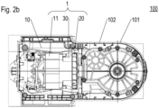
- the arm component 100 comprises a housing 101 encasing, in particular, a gear unit 102 and a drive unit 1 according to an embodiment of the present invention, as is seen in Figure 2b showing a longitudinal section of the arm component 100.
- the drive unit 1 comprises a stator 11 and a rotor 12 of an electric motor 10, an impeller 20, and an air-guiding element 30.
- the air-guiding element 30 forms (alone or in combination with another component such as the stator 11) one or various passage/s extending along a radially outer surface S of the stator 11, through a respective gap G 1 , G 2 , G 3 , G 4 delimited by the stator 11 and the air-guiding element 30, and to the impeller 20.
Landscapes
- Engineering & Computer Science (AREA)
- Power Engineering (AREA)
- Structures Of Non-Positive Displacement Pumps (AREA)
Abstract
Description
- The present invention concerns a drive unit of or for a household appliance. The invention further concerns a household appliance and an arm component of a kitchen machine respectively comprising such drive unit.
- Many commonly known household appliances integrate at least one drive unit comprising an electric motor in a housing. Therein, to provide a preferably small appliance, a space allocated for the drive unit is typically intended to be kept tight. On the other hand, the electric motor generates heat which may be detrimental to the various components of the household appliance (such as an electronics and/or the housing, for example), or which may even be harmful for a user of the household appliance. As a consequence, for construction of the household appliances, respective technical demands have to be considered, such as regarding a used material and/or a spatial arrangement of the various elements comprised by the appliance.
- It was an object of the present invention to provide a technique simplifying the construction of preferably compact household appliances comprising an electric motor.
- The object is achieved by a drive unit according to
claim 1, by an arm component according to claim 8, and by a household appliance according to claim 9. Advantageous embodiments are disclosed in the dependent claims, the description and the figures. - A drive unit according to the present invention is a component of or for a household appliance, in particular, a kitchen machine (such as an electric food processor or a multi-purpose kitchen appliance), an electric blender, a stick blender or a handheld electric mixer kitchen appliance, for instance.
- The drive unit comprises a stator and a (preferably internal) rotor of an electric motor, the rotor being configured to rotate about a rotor axis. The drive unit further comprises an impeller configured to rotate about the rotor axis so as to produce a heat dissipating air flow, thus to cool the electric motor. In particular, the impeller is advantageously fixed to a rotor shaft. Moreover, the drive unit comprises an air-guiding element at least a portion of which is arranged between the stator and the impeller.
- Therein, the air-guiding element forms (alone or in combination with another component such as the stator) one or various passage/s extending along a radially outer surface of the stator, through a respective gap delimited by the stator and the air-guiding element, and to the impeller.
- The number of said passages in particular may be at least two, at least three, or at least four.
- In particular, on the stator's side, the gap or - if the air-guiding element forms various passages - at least one of the various gaps may at least partially be delimited by a portion of the radially outer surface and/or by an edge thereof. Additionally or alternatively, the gap or - in case of various passages - (the) at least one of the gaps may at least partially be delimited, on the air-guiding element's side, by a radially inner surface of the air-guiding element and/or by an edge of said radially inner surface.
- As is to be noted, if not otherwise indicated, the terms "radial", "axial" and "circumferential" in this document always relate to the rotor axis, i.e., to a designated axis of rotation of the rotor. In particular, the radially outer surface of the stator thus is a stator's surface facing away from the rotor, and the radially inner surface of the air-guiding element is a surface of this element which faces (directly or inclined thereto) the rotor axis.
- The passage/s thus connect/s a space, which in radial direction is delimited by (at least a region of) the radial outer surface of the stator, with the impeller. As a consequence, in operation of the electric motor, an air flow generated by the rotating impeller passes the radial outer surface of the stator, thereby cooling the stator from the radial outer side. Moreover, a flow resistance of an air stream likewise generated by the rotating impeller and running through the radial inner space of the stator, in which the rotor rotates, is reduced. As a consequence, a velocity of the air stream and, thereby, an air stream rate are increased, which improves the heat dissipating and thus cooling effect of the air-guiding element.
- Due to the thus improved heat dissipation, consideration of disadvantageous heat effects on further components of the household appliance, such as on a housing and/or on electronic parts, can be reduced when constructing the household appliance. The construction is thus simplified. In particular, cheaper materials (such as plastic) having less heat resistance can be used (in particular for the housing) and/or the household appliance's component comprising the drive unit or even the household appliance itself can be produced more compact, without disadvantageously affecting other components such as an electronics or a gear system of the household appliance, i.e., without imparing a stable performance thereof. In addition, the improved heat dissipation reduces a temperature of exterior components of the household appliance, such as a housing, a grip and/or a tool thereof. As a consequence, the operation of the household appliance results to be more comfortable for a user, and even possible heat injuries may be effectively prevented.
- According to advantageous embodiments, the drive unit according to the present invention may be integrated or designated to be integrated in an arm component of a kitchen machine, in particular in an arm component according to an embodiment of the present invention:
An arm component according to the present invention accordingly is a component of a kitchen machine (such as an electric food processor or a multi-purpose kitchen appliance), which component comprises a drive unit according to an embodiment of the present invention, a gear system configured to be driven by the drive unit, and a housing which at least partially encases the drive unit and the gear system. - The housing may preferably be at least partially made of plastics.
- The gear system may be configured to hold a tool for processing food contained in a receptacle, wherein in an orientation designated for use of the kitchen machine, the tool may advantageously extend from above into the receptacle.
- In particular, the arm component may be (possibly pivotably) attached or may be configured to be (possibly pivotably) attached to a base component of the kitchen machine.
- A household appliance according to the present invention comprises a drive unit according to an embodiment of the present invention.
- The household appliance may in particular be a kitchen appliance such as an electric blender, a stick blender or a handheld electric mixer, or such as a kitchen machine (e.g., an electric food processor or a multi-purpose kitchen appliance). Such kitchen machine may comprise a base component and, (advantageously pivotably) attached thereto, an arm component according to an embodiment of the present invention.
- The base component may advantageously provide a foot of the kitchen machine. In particular, the base component may comprise a seat surface a receptacle is to be positioned on during processing food contained in the receptacle with the kitchen machine.
- Preferably, the air-guiding element is arranged on a suction side of the impeller, such that the air flow generated by the rotating impeller is sucked from the stator to the impeller.
- In particular, the gap or - in case various passages are formed - at least one of the gaps is preferably formed at an axial side of the air-guiding element which side faces away from the impeller.
- According to advantageous embodiments of the present invention, the gap or - if the air-guiding element forms various passages - the gaps together extend over at least a quarter or at least a third of a circumference of the outer surface of the stator. Accordingly, in operation of the electric motor, the stator is flushed in at least a quarter or at least a third of its circumference by the air flow/s generated by the rotating impeller and flowing along the passage/s. As a consequence, a particularly effective cooling is achieved.
- In particular, the gap or - in case the air-guiding element forms various passages - at least one of the gaps may have a length (measured in circumferential direction of the stator) of at least 1cm or at least 1.3cm or at least 3cm or at least 4cm.
- Advantageously, the gap or - in embodiments where the air-guiding element forms various passages - at least one of the gaps may have a width of at least 3mm or at least 4.5mm or at least 6mm. Therein, the width is measured at a widest region of the gap and orthogonally to the stator surface or to the stator edge respectively delimiting the respective gap and facing the air-guiding element. In particular, the width is understood to be the greatest distance appearing between points A on the air-guiding element's surface or air-guiding element's edge delimiting the gap and points B of the stator edge or the stator surface respectively delimiting the gap and facing the air-guiding element, the distance measured orthogonally to said surface or edge of the stator.
- Such length and/or width of the gap/s facilitate that the impeller generates an air flow having a particularly advantageous cooling effect.
- Additionally or alternatively, the length of the (at least one) gap may be at most 7cm or at most 5cm, and/or the width of the (at least one) gap may be at most 8mm or at most 7mm.
- Such dimension/s facilitate an advantageous compact shape of the drive unit.
- According to advantageous embodiments, a portion of the passage or - in embodiments where the air-guiding element forms various passages - of at least one of the passages extends along a corner formed by the air-guiding element and running in axial direction. In particular, the gap or - in embodiments where the air-guiding element forms various passages - at least one of the gaps may be formed at an axial end of the at least one corner. According to advantageous embodiments, (disregarding a possible chamfering) the at least one corner is rectangular.
- Additionally or alternatively, the gap or - in case of various passages - at least one of the gaps may have a straight, longitudinal shape. Such gap may in particular be delimited by at least two parallel surfaces or edges (in particular of a respective one of the stator and/or the air-guiding element).
- These embodiments provide for an advantageous air flow while at the same time utilising particularly effectively an installation space within a housing of the household appliance.
- The air-guiding element may comprise at least one portion extending in axial direction into a radial periphery of the stator. Such portion may thus face a respective radially outer surface region of the stator. In such embodiments, the passage or - in embodiments where various passages are formed - at least one of the various passages may extend between such at least one portion of the air-guiding element and said surface region of the stator. Accordingly, the respective passage runs through a channel formed between the stator and said portion of the air-guiding element. With such a channel, a particularly straight and fast air flow having a particularly good cooling effect can be generated.
- In what follows, preferred embodiments of the present invention are explained with respect to the accompanying drawings. As is to be understood, the various elements and components are depicted as examples only, and they may be facultative and/or combined in a manner different than that depicted. Reference signs for related elements are used comprehensively and not defined again for each figure.
- Shown is schematically in
- Fig. 1a:
- an exemplary embodiment of a drive unit according to the present invention in a sectional view;
- Fig. 1b:
- the drive unit of
Figure 1a as installed and in a cross section; - Fig. 1c:
- the drive unit of
Figures 1a, 1b in perspective view and without its rotor; - Fig. 2a:
- an arm component according to an exemplary embodiment of the present invention in perspective view; and
- Fig. 2b:
- a cross section of the arm component of
Figure 2a . -
Figure 1a presents a sectional view providing insight into adrive unit 1 according to an exemplary embodiment of the present invention. Thedrive unit 1 comprises arotor 12 of anelectric motor 10, therotor 12 configured to rotate about a rotor axis X; a rotor shaft connected to the rotor is omitted inFigure 1 . Thedrive unit 1 further comprises astator 11 of theelectric motor 10. Therein, therotor 12 is an internal rotor, thestator 11 thus radially surrounds the rotor 12 (with respect to the rotor axis X). - Additionally, the
drive unit 1 comprises animpeller 20 which is fixed to the (not shown) rotor shaft and which is thereby likewise configured to rotate about the rotor axis X. Therein, therotor 12 and thestator 11 are preferably arranged on a suction side of theimpeller 20. In operation, i.e., when the impeller rotates, it generates a heat dissipating air flow through the rotating rotor. - In axial direction (i.e., in direction of the rotor axis X), an air-guiding
element 30 of thedrive unit 1 is arranged partially between theimpeller 20 and both therotor 12 and thestator 11. Therein, the air-guidingelement 30 forms various passages P1, P2, two of which are visible inFigure 1a . The passages P1, P2 each extend along a radial outer surface S of thestator 11 and to theimpeller 20, thereby running through a respective gap G1, G2 delimited by thestator 11 and the air-guidingelement 30. Therein, one of the gaps (inFigure 1a referenced as G1) is delimited by an edge of the stator's outer surface S and an edge of the air-guidingelement 30, while another one of the gaps (inFigure 1a referenced as G2) is delimited by the outer surface S of thestator 11 and a radially inner surface of aportion 31 of the air-guidingelement 30, whichportion 31 in the exemplary embodiment shown extends in axial direction into a radial periphery of thestator 11. - As seen in
Figure 1a , the passages P1, P2 each further run through an interspace I formed axially between theimpeller 20 and both thestator 11 and therotor 12. In radial direction, the interspace I is delimited by the air-guidingelement 30. - The passages P1, P2 therefore cause an air flow generated by the rotating
impeller 20 to pass the radially outer surface S. Accordingly, heat is dissipated also from a radial outer environment of thestator 11. Moreover, as a flow resistance is reduced by the passages P1, P2, a velocity of the air stream through therotor 12 is increased. - As a consequence, heat dissipation from the stator and the rotor is improved, such that the production of a household appliance containing the
drive unit 1 is simplified, in particular with regard to appropriate positions of electronic components and a material of a housing of the household appliance, while the appliance itself can be kept compact. -
Figure 1b depicts thedrive unit 1, installed in ahousehold appliance 100 such as a kitchen machine, in a cross section along a plane orthogonal to the rotor axis X being a centre axis of arotor shaft 13. - As depicted in
Figure 1b , the air-guidingelement 30 forms two rectangular (albeit chamfered)corners stator 11 and the air-guidingelement 30, the gaps G3, G4 having an essentially triangular shape. - Accordingly, respective passages extend along the radially outer surface S of the
stator 11, through said gaps G3, G4, along a respective one of thecorners Figure 1b ). Therein, as apparent fromFigure 1c , the gaps G3, G4 each are formed at a respective axial end of a respective onecorner - As can be further taken from
Figure 1b , in a cross section taken orthogonal to the rotor axis X, the gaps G1 and G2 each have a straight, longitudinal shape. - Therein, the gap G1 has a length L1 (measured in circumferential direction of the stator 11) and a width W1 (measured at the widest region of the gap G1 and orthogonally to the stator edge delimiting the gap G1 and facing the air-guiding element 30). Preferably, L1 ≥ 3cm or even L1≥ 4cm holds. Additionally or alternatively, W1 ≥ 3mm or W1 ≥ 4mm may preferably hold. In the exemplary embodiment shown, the gap G2 has the same width and length, respectively, as the gap G1.
- As further indicated in
Figure 1b , the gap G3 has a length L3 (measured in circumferential direction of the stator 11) and a width W3 (measured at the widest region of the gap G3 and orthogonally to the stator edge delimiting the gap G3 and facing the air-guiding element 30). Preferably, L1 ≥ 1 cm or even L1≥ 1.3cm holds. Additionally or alternatively, W3 ≥ 4.5mm or W3 ≥ 6mm may preferably hold. In the exemplary embodiment shown, the gap G4 has the same width and length, respectively, as the gap G3. - In
Figure 1c , thedrive unit 1 ofFigures 1a, 1b is shown in perspective view and without the rotor, whereby an insight into the space encompassed by the stator and the air-guidingelement 30 is given and the construction of thestator 11 and the air-guidingelement 30 is further illustrated. -
Figure 2a shows anarm component 100 according to an exemplary embodiment of the present invention in perspective view. In the case depicted, the arm component is a component of a kitchen machine, and it is configured to be pivotably mounted to a base of the kitchen machine (not shown). Thearm component 100 comprises ahousing 101 encasing, in particular, agear unit 102 and adrive unit 1 according to an embodiment of the present invention, as is seen inFigure 2b showing a longitudinal section of thearm component 100. - Disclosed is a
drive unit 1 of or for a household appliance. Thedrive unit 1 comprises astator 11 and arotor 12 of anelectric motor 10, animpeller 20, and an air-guidingelement 30. The air-guidingelement 30 forms (alone or in combination with another component such as the stator 11) one or various passage/s extending along a radially outer surface S of thestator 11, through a respective gap G1, G2, G3, G4 delimited by thestator 11 and the air-guidingelement 30, and to theimpeller 20. - Further disclosed are an
arm component 100 of a kitchen machine, and a household appliance respectively comprisingsuch drive unit 1. -
- 1
- drive unit
- 10
- electric motor
- 11
- stator
- 12
- rotor
- 13
- rotor shaft
- 20
- impeller
- 30
- air-guiding element
- 31
- portion of air-guiding element
- 32
- corner
- 33
- corner
- 100
- arm component
- 101
- housing
- 102
- gear system
- G1
- gap
- G2
- gap
- G3
- gap
- G4
- gap
- I
- axial interspace between
stator 11 andimpeller 20 - L1
- length of gap G1
- L3
- length of gap G3
- P1
- passage
- P2
- passage
- S
- radially outer surface of the
stator 11 - W1
- width of gap G1
- W3
- width of gap G3
- X
- rotor axis
Claims (10)
- Drive unit (1) of or for a household appliance, the drive unit comprising- a stator (11) and a rotor (12) of an electric motor (10),- an impeller (20),- and an air-guiding element (30) arranged at least partially between the stator (11) and the impeller (20),wherein the air-guiding element (30) forms one or various passage/s (P1, P2) extending along a radially outer surface (S) of the stator (11), through a respective gap (G1, G2, G3, G4) delimited by the stator (11) and by the air-guiding element (30), and to the impeller (20).
- Drive unit (1) according to claim 1, wherein in circumferential direction, the gap/s (G1, G2, G3, G4) together extend over at least a quarter or at least a third of a circumference of the radially outer surface (S) of the stator (11).
- Drive unit according to one of claims 1 or 2, wherein the gap or - in case of various passages - at least one of the gaps (G1, G2, G3, G4) has a width (W1, W3) of at least 3mm or at least 4.5mm or at least 6mm.
- Drive unit according to one of the preceding claims, wherein in circumferential direction, the gap or - in case of various passages - at least one of the gaps (G1, G2, G3, G4) has a length (L1, L3) of at least 1cm or at least 1.3cm or at least 3cm or at least 4cm.
- Drive unit (1) according to one of the preceding claims, wherein the air-guiding element (30) forms at least one corner (32, 33) running in axial direction, wherein the gap or - in case of various passages - at least one of the gaps (G3, G4) is formed at an axial end of the at least one corner (32, 33).
- Drive unit (1) according to one of the preceding claims, wherein in a cross section taken orthogonal to a rotor axis (X) of the rotor (12), the gap or - in case of various passages (P1, P2) - at least one of the gaps (G1, G2) has a straight, longitudinal shape.
- Drive unit (1) according to one of the preceding claims, wherein the passage or - in case of various passages - at least one of the various passages (P2) runs between a region of the stator's radially outer surface (S) and an air-guiding element's portion (31) extending in axial direction into a radial periphery of the stator (11).
- Arm component (100) of a kitchen machine, the arm component comprising a drive unit (1) according to one of the preceding claims, a gear system (102) configured to be driven by the drive unit, and a housing (101) encasing the drive unit (1) and the gear system (102).
- Household appliance comprising a drive unit (1) according to one of claims 1 to 7.
- Household appliance according to claim 9, the household appliance being a kitchen machine comprising a base component and, attached thereto, an arm component (100) according to claim 8.
Priority Applications (1)
| Application Number | Priority Date | Filing Date | Title |
|---|---|---|---|
| EP23150506.6A EP4398460A1 (en) | 2023-01-05 | 2023-01-05 | Drive unit, arm component of a kitchen machine, and house-hold appliance |
Applications Claiming Priority (1)
| Application Number | Priority Date | Filing Date | Title |
|---|---|---|---|
| EP23150506.6A EP4398460A1 (en) | 2023-01-05 | 2023-01-05 | Drive unit, arm component of a kitchen machine, and house-hold appliance |
Publications (1)
| Publication Number | Publication Date |
|---|---|
| EP4398460A1 true EP4398460A1 (en) | 2024-07-10 |
Family
ID=84829820
Family Applications (1)
| Application Number | Title | Priority Date | Filing Date |
|---|---|---|---|
| EP23150506.6A Pending EP4398460A1 (en) | 2023-01-05 | 2023-01-05 | Drive unit, arm component of a kitchen machine, and house-hold appliance |
Country Status (1)
| Country | Link |
|---|---|
| EP (1) | EP4398460A1 (en) |
Citations (13)
| Publication number | Priority date | Publication date | Assignee | Title |
|---|---|---|---|---|
| US4903497A (en) * | 1987-09-04 | 1990-02-27 | Bernard Zimmern | Methods and devices for cooling a motor of a refrigerating machine with liquid and economizer gas |
| DE202006014140U1 (en) * | 2005-08-26 | 2006-11-09 | BSH Bosch und Siemens Hausgeräte GmbH | Electric motor operated kitchen equipment e.g. stand alone or universal food processor, for house, has electric motor, and metallic cooling wheel e.g. fan, firmly connected with motor shaft for cooling rotor windings and/or gear worm |
| ES1067534U (en) * | 2008-03-17 | 2008-05-16 | Coprecites, S.L | Vacuum pump adaptable to an appliance appliance (Machine-translation by Google Translate, not legally binding) |
| US20110150637A1 (en) * | 2005-06-06 | 2011-06-23 | Gebr. Becker Gmbh | Radial fan |
| CN202260790U (en) * | 2011-09-23 | 2012-05-30 | 宁波菲仕电机技术有限公司 | Air-cooling device of servo motor |
| WO2016194697A1 (en) * | 2015-05-29 | 2016-12-08 | 日本電産株式会社 | Blower apparatus and vacuum cleaner |
| CN103580381B (en) * | 2012-07-27 | 2018-04-03 | 安德烈亚斯·斯蒂尔两合公司 | Electric drive motor for work implement |
| CN108626147A (en) * | 2017-03-17 | 2018-10-09 | 日本电产株式会社 | Air-supply arrangement and dust catcher |
| CN209300913U (en) * | 2018-07-26 | 2019-08-27 | 广东美的生活电器制造有限公司 | Base and food cooking machine |
| CN106921264B (en) * | 2015-10-30 | 2020-05-05 | 德国福维克控股公司 | Motor and motor-driven cleaning device |
| CN111425416A (en) * | 2019-01-09 | 2020-07-17 | 日本电产株式会社 | Air supply device and dust collector |
| US20210317836A1 (en) * | 2017-03-16 | 2021-10-14 | Lg Electronics Inc. | Fan motor |
| US11191913B2 (en) * | 2011-08-05 | 2021-12-07 | Resmed Motor Technologies Inc. | Blower |
-
2023
- 2023-01-05 EP EP23150506.6A patent/EP4398460A1/en active Pending
Patent Citations (13)
| Publication number | Priority date | Publication date | Assignee | Title |
|---|---|---|---|---|
| US4903497A (en) * | 1987-09-04 | 1990-02-27 | Bernard Zimmern | Methods and devices for cooling a motor of a refrigerating machine with liquid and economizer gas |
| US20110150637A1 (en) * | 2005-06-06 | 2011-06-23 | Gebr. Becker Gmbh | Radial fan |
| DE202006014140U1 (en) * | 2005-08-26 | 2006-11-09 | BSH Bosch und Siemens Hausgeräte GmbH | Electric motor operated kitchen equipment e.g. stand alone or universal food processor, for house, has electric motor, and metallic cooling wheel e.g. fan, firmly connected with motor shaft for cooling rotor windings and/or gear worm |
| ES1067534U (en) * | 2008-03-17 | 2008-05-16 | Coprecites, S.L | Vacuum pump adaptable to an appliance appliance (Machine-translation by Google Translate, not legally binding) |
| US11191913B2 (en) * | 2011-08-05 | 2021-12-07 | Resmed Motor Technologies Inc. | Blower |
| CN202260790U (en) * | 2011-09-23 | 2012-05-30 | 宁波菲仕电机技术有限公司 | Air-cooling device of servo motor |
| CN103580381B (en) * | 2012-07-27 | 2018-04-03 | 安德烈亚斯·斯蒂尔两合公司 | Electric drive motor for work implement |
| WO2016194697A1 (en) * | 2015-05-29 | 2016-12-08 | 日本電産株式会社 | Blower apparatus and vacuum cleaner |
| CN106921264B (en) * | 2015-10-30 | 2020-05-05 | 德国福维克控股公司 | Motor and motor-driven cleaning device |
| US20210317836A1 (en) * | 2017-03-16 | 2021-10-14 | Lg Electronics Inc. | Fan motor |
| CN108626147A (en) * | 2017-03-17 | 2018-10-09 | 日本电产株式会社 | Air-supply arrangement and dust catcher |
| CN209300913U (en) * | 2018-07-26 | 2019-08-27 | 广东美的生活电器制造有限公司 | Base and food cooking machine |
| CN111425416A (en) * | 2019-01-09 | 2020-07-17 | 日本电产株式会社 | Air supply device and dust collector |
Similar Documents
| Publication | Publication Date | Title |
|---|---|---|
| US8157524B2 (en) | Axial flow fan with hub isolation slots | |
| CA2734362C (en) | Fan | |
| CN100529411C (en) | Cooling pump, electric device and personnel computer | |
| US6435828B1 (en) | Split blade radial fan | |
| US8593022B2 (en) | Electric motor with heat dissipation structure | |
| CN100517917C (en) | Power tool | |
| US7416384B2 (en) | Electric blower and vacuum cleaner using same | |
| JPH04265492A (en) | High speed pump | |
| US12135035B2 (en) | Motor assembly and cleaner comprising same | |
| US6193478B1 (en) | Construction of a fan | |
| US6779612B2 (en) | Power tool having air discharge windows | |
| US20060226718A1 (en) | Closed enclosure electric machine | |
| CN209948889U (en) | Motors, blowers and vacuum cleaners | |
| US5855469A (en) | End seal design for blower | |
| JP4635563B2 (en) | Electric blower | |
| CN101047324A (en) | Stator for electric moter | |
| JP7816676B2 (en) | electric motor | |
| JPH07245915A (en) | Rotating electric machine | |
| JP2725970B2 (en) | Electric blower | |
| JP6690603B2 (en) | Centrifugal blower | |
| JP2002127048A (en) | Motor-driven tool | |
| JP2018001284A (en) | Electric power tool | |
| CN216390676U (en) | Motor, rotor support and electric product | |
| KR200237059Y1 (en) | Cooling structure of the motor | |
| KR102373383B1 (en) | Stator core |
Legal Events
| Date | Code | Title | Description |
|---|---|---|---|
| PUAI | Public reference made under article 153(3) epc to a published international application that has entered the european phase |
Free format text: ORIGINAL CODE: 0009012 |
|
| STAA | Information on the status of an ep patent application or granted ep patent |
Free format text: STATUS: THE APPLICATION HAS BEEN PUBLISHED |
|
| AK | Designated contracting states |
Kind code of ref document: A1 Designated state(s): AL AT BE BG CH CY CZ DE DK EE ES FI FR GB GR HR HU IE IS IT LI LT LU LV MC ME MK MT NL NO PL PT RO RS SE SI SK SM TR |
|
| STAA | Information on the status of an ep patent application or granted ep patent |
Free format text: STATUS: REQUEST FOR EXAMINATION WAS MADE |
|
| 17P | Request for examination filed |
Effective date: 20250110 |
|
| STAA | Information on the status of an ep patent application or granted ep patent |
Free format text: STATUS: EXAMINATION IS IN PROGRESS |
|
| 17Q | First examination report despatched |
Effective date: 20250409 |