EP4398433A1 - Schaltung und verfahren zur unterdrückung des stromversorgungsstartanstiegs, ladevorrichtung und speichermedium - Google Patents
Schaltung und verfahren zur unterdrückung des stromversorgungsstartanstiegs, ladevorrichtung und speichermedium Download PDFInfo
- Publication number
- EP4398433A1 EP4398433A1 EP22863102.4A EP22863102A EP4398433A1 EP 4398433 A1 EP4398433 A1 EP 4398433A1 EP 22863102 A EP22863102 A EP 22863102A EP 4398433 A1 EP4398433 A1 EP 4398433A1
- Authority
- EP
- European Patent Office
- Prior art keywords
- power supply
- circuit
- terminal
- resistance
- suppressing
- Prior art date
- Legal status (The legal status is an assumption and is not a legal conclusion. Google has not performed a legal analysis and makes no representation as to the accuracy of the status listed.)
- Granted
Links
Images
Classifications
-
- H—ELECTRICITY
- H02—GENERATION; CONVERSION OR DISTRIBUTION OF ELECTRIC POWER
- H02H—EMERGENCY PROTECTIVE CIRCUIT ARRANGEMENTS
- H02H9/00—Emergency protective circuit arrangements for limiting excess current or voltage without disconnection
- H02H9/001—Emergency protective circuit arrangements for limiting excess current or voltage without disconnection limiting speed of change of electric quantities, e.g. soft switching on or off
-
- H—ELECTRICITY
- H02—GENERATION; CONVERSION OR DISTRIBUTION OF ELECTRIC POWER
- H02J—ELECTRIC POWER NETWORKS; CIRCUIT ARRANGEMENTS OR SYSTEMS FOR SUPPLYING OR DISTRIBUTING ELECTRIC POWER; SYSTEMS FOR STORING ELECTRIC ENERGY
- H02J7/00—Circuit arrangements for charging or discharging batteries or for supplying loads from batteries
- H02J7/60—Circuit arrangements for charging or discharging batteries or for supplying loads from batteries including safety or protection arrangements
- H02J7/62—Circuit arrangements for charging or discharging batteries or for supplying loads from batteries including safety or protection arrangements against overcurrent
-
- B—PERFORMING OPERATIONS; TRANSPORTING
- B60—VEHICLES IN GENERAL
- B60L—PROPULSION OF ELECTRICALLY-PROPELLED VEHICLES; SUPPLYING ELECTRIC POWER FOR AUXILIARY EQUIPMENT OF ELECTRICALLY-PROPELLED VEHICLES; ELECTRODYNAMIC BRAKE SYSTEMS FOR VEHICLES IN GENERAL; MAGNETIC SUSPENSION OR LEVITATION FOR VEHICLES; MONITORING OPERATING VARIABLES OF ELECTRICALLY-PROPELLED VEHICLES; ELECTRIC SAFETY DEVICES FOR ELECTRICALLY-PROPELLED VEHICLES
- B60L3/00—Electric devices on electrically-propelled vehicles for safety purposes; Monitoring operating variables, e.g. speed, deceleration or energy consumption
- B60L3/04—Cutting off the power supply under fault conditions
-
- B—PERFORMING OPERATIONS; TRANSPORTING
- B60—VEHICLES IN GENERAL
- B60L—PROPULSION OF ELECTRICALLY-PROPELLED VEHICLES; SUPPLYING ELECTRIC POWER FOR AUXILIARY EQUIPMENT OF ELECTRICALLY-PROPELLED VEHICLES; ELECTRODYNAMIC BRAKE SYSTEMS FOR VEHICLES IN GENERAL; MAGNETIC SUSPENSION OR LEVITATION FOR VEHICLES; MONITORING OPERATING VARIABLES OF ELECTRICALLY-PROPELLED VEHICLES; ELECTRIC SAFETY DEVICES FOR ELECTRICALLY-PROPELLED VEHICLES
- B60L53/00—Methods of charging batteries, specially adapted for electric vehicles; Charging stations or on-board charging equipment therefor; Exchange of energy storage elements in electric vehicles
- B60L53/60—Monitoring or controlling charging stations
- B60L53/62—Monitoring or controlling charging stations in response to charging parameters, e.g. current, voltage or electrical charge
-
- H—ELECTRICITY
- H01—ELECTRIC ELEMENTS
- H01H—ELECTRIC SWITCHES; RELAYS; SELECTORS; EMERGENCY PROTECTIVE DEVICES
- H01H47/00—Circuit arrangements not adapted to a particular application of the relay and designed to obtain desired operating characteristics or to provide energising current
- H01H47/02—Circuit arrangements not adapted to a particular application of the relay and designed to obtain desired operating characteristics or to provide energising current for modifying the operation of the relay
-
- H—ELECTRICITY
- H02—GENERATION; CONVERSION OR DISTRIBUTION OF ELECTRIC POWER
- H02H—EMERGENCY PROTECTIVE CIRCUIT ARRANGEMENTS
- H02H9/00—Emergency protective circuit arrangements for limiting excess current or voltage without disconnection
- H02H9/001—Emergency protective circuit arrangements for limiting excess current or voltage without disconnection limiting speed of change of electric quantities, e.g. soft switching on or off
- H02H9/002—Emergency protective circuit arrangements for limiting excess current or voltage without disconnection limiting speed of change of electric quantities, e.g. soft switching on or off limiting inrush current on switching on of inductive loads subjected to remanence, e.g. transformers
-
- H—ELECTRICITY
- H02—GENERATION; CONVERSION OR DISTRIBUTION OF ELECTRIC POWER
- H02H—EMERGENCY PROTECTIVE CIRCUIT ARRANGEMENTS
- H02H9/00—Emergency protective circuit arrangements for limiting excess current or voltage without disconnection
- H02H9/005—Emergency protective circuit arrangements for limiting excess current or voltage without disconnection avoiding undesired transient conditions
-
- H—ELECTRICITY
- H02—GENERATION; CONVERSION OR DISTRIBUTION OF ELECTRIC POWER
- H02H—EMERGENCY PROTECTIVE CIRCUIT ARRANGEMENTS
- H02H9/00—Emergency protective circuit arrangements for limiting excess current or voltage without disconnection
- H02H9/02—Emergency protective circuit arrangements for limiting excess current or voltage without disconnection responsive to excess current
-
- H—ELECTRICITY
- H02—GENERATION; CONVERSION OR DISTRIBUTION OF ELECTRIC POWER
- H02J—ELECTRIC POWER NETWORKS; CIRCUIT ARRANGEMENTS OR SYSTEMS FOR SUPPLYING OR DISTRIBUTING ELECTRIC POWER; SYSTEMS FOR STORING ELECTRIC ENERGY
- H02J7/00—Circuit arrangements for charging or discharging batteries or for supplying loads from batteries
- H02J7/02—Circuit arrangements for charging or discharging batteries or for supplying loads from batteries for charging batteries from AC mains by converters
-
- H—ELECTRICITY
- H02—GENERATION; CONVERSION OR DISTRIBUTION OF ELECTRIC POWER
- H02J—ELECTRIC POWER NETWORKS; CIRCUIT ARRANGEMENTS OR SYSTEMS FOR SUPPLYING OR DISTRIBUTING ELECTRIC POWER; SYSTEMS FOR STORING ELECTRIC ENERGY
- H02J7/00—Circuit arrangements for charging or discharging batteries or for supplying loads from batteries
- H02J7/60—Circuit arrangements for charging or discharging batteries or for supplying loads from batteries including safety or protection arrangements
-
- H—ELECTRICITY
- H02—GENERATION; CONVERSION OR DISTRIBUTION OF ELECTRIC POWER
- H02J—ELECTRIC POWER NETWORKS; CIRCUIT ARRANGEMENTS OR SYSTEMS FOR SUPPLYING OR DISTRIBUTING ELECTRIC POWER; SYSTEMS FOR STORING ELECTRIC ENERGY
- H02J7/00—Circuit arrangements for charging or discharging batteries or for supplying loads from batteries
- H02J7/80—Circuit arrangements for charging or discharging batteries or for supplying loads from batteries including monitoring or indicating arrangements
-
- B—PERFORMING OPERATIONS; TRANSPORTING
- B60—VEHICLES IN GENERAL
- B60L—PROPULSION OF ELECTRICALLY-PROPELLED VEHICLES; SUPPLYING ELECTRIC POWER FOR AUXILIARY EQUIPMENT OF ELECTRICALLY-PROPELLED VEHICLES; ELECTRODYNAMIC BRAKE SYSTEMS FOR VEHICLES IN GENERAL; MAGNETIC SUSPENSION OR LEVITATION FOR VEHICLES; MONITORING OPERATING VARIABLES OF ELECTRICALLY-PROPELLED VEHICLES; ELECTRIC SAFETY DEVICES FOR ELECTRICALLY-PROPELLED VEHICLES
- B60L53/00—Methods of charging batteries, specially adapted for electric vehicles; Charging stations or on-board charging equipment therefor; Exchange of energy storage elements in electric vehicles
- B60L53/60—Monitoring or controlling charging stations
-
- H—ELECTRICITY
- H01—ELECTRIC ELEMENTS
- H01H—ELECTRIC SWITCHES; RELAYS; SELECTORS; EMERGENCY PROTECTIVE DEVICES
- H01H47/00—Circuit arrangements not adapted to a particular application of the relay and designed to obtain desired operating characteristics or to provide energising current
- H01H47/002—Monitoring or fail-safe circuits
-
- H—ELECTRICITY
- H02—GENERATION; CONVERSION OR DISTRIBUTION OF ELECTRIC POWER
- H02J—ELECTRIC POWER NETWORKS; CIRCUIT ARRANGEMENTS OR SYSTEMS FOR SUPPLYING OR DISTRIBUTING ELECTRIC POWER; SYSTEMS FOR STORING ELECTRIC ENERGY
- H02J2105/00—Networks for supplying or distributing electric power characterised by their spatial reach or by the load
- H02J2105/30—Networks for supplying or distributing electric power characterised by their spatial reach or by the load the load networks being external to vehicles, i.e. exchanging power with vehicles
- H02J2105/33—Networks for supplying or distributing electric power characterised by their spatial reach or by the load the load networks being external to vehicles, i.e. exchanging power with vehicles exchanging power with road vehicles
- H02J2105/37—Networks for supplying or distributing electric power characterised by their spatial reach or by the load the load networks being external to vehicles, i.e. exchanging power with vehicles exchanging power with road vehicles exchanging power with electric vehicles [EV] or with hybrid electric vehicles [HEV]
-
- Y—GENERAL TAGGING OF NEW TECHNOLOGICAL DEVELOPMENTS; GENERAL TAGGING OF CROSS-SECTIONAL TECHNOLOGIES SPANNING OVER SEVERAL SECTIONS OF THE IPC; TECHNICAL SUBJECTS COVERED BY FORMER USPC CROSS-REFERENCE ART COLLECTIONS [XRACs] AND DIGESTS
- Y02—TECHNOLOGIES OR APPLICATIONS FOR MITIGATION OR ADAPTATION AGAINST CLIMATE CHANGE
- Y02T—CLIMATE CHANGE MITIGATION TECHNOLOGIES RELATED TO TRANSPORTATION
- Y02T10/00—Road transport of goods or passengers
- Y02T10/60—Other road transportation technologies with climate change mitigation effect
- Y02T10/70—Energy storage systems for electromobility, e.g. batteries
-
- Y—GENERAL TAGGING OF NEW TECHNOLOGICAL DEVELOPMENTS; GENERAL TAGGING OF CROSS-SECTIONAL TECHNOLOGIES SPANNING OVER SEVERAL SECTIONS OF THE IPC; TECHNICAL SUBJECTS COVERED BY FORMER USPC CROSS-REFERENCE ART COLLECTIONS [XRACs] AND DIGESTS
- Y02—TECHNOLOGIES OR APPLICATIONS FOR MITIGATION OR ADAPTATION AGAINST CLIMATE CHANGE
- Y02T—CLIMATE CHANGE MITIGATION TECHNOLOGIES RELATED TO TRANSPORTATION
- Y02T10/00—Road transport of goods or passengers
- Y02T10/60—Other road transportation technologies with climate change mitigation effect
- Y02T10/7072—Electromobility specific charging systems or methods for batteries, ultracapacitors, supercapacitors or double-layer capacitors
-
- Y—GENERAL TAGGING OF NEW TECHNOLOGICAL DEVELOPMENTS; GENERAL TAGGING OF CROSS-SECTIONAL TECHNOLOGIES SPANNING OVER SEVERAL SECTIONS OF THE IPC; TECHNICAL SUBJECTS COVERED BY FORMER USPC CROSS-REFERENCE ART COLLECTIONS [XRACs] AND DIGESTS
- Y02—TECHNOLOGIES OR APPLICATIONS FOR MITIGATION OR ADAPTATION AGAINST CLIMATE CHANGE
- Y02T—CLIMATE CHANGE MITIGATION TECHNOLOGIES RELATED TO TRANSPORTATION
- Y02T90/00—Enabling technologies or technologies with a potential or indirect contribution to GHG emissions mitigation
- Y02T90/10—Technologies relating to charging of electric vehicles
- Y02T90/14—Plug-in electric vehicles
Definitions
- the present disclosure relates to the technical field of electric power, in particular to a circuit, a method for suppressing a power supply starting surge, a charging apparatus, and a storage medium.
- the safety of high-current power supply modules has attracted more attention, with the popularization of high-current charging technology for electric vehicles.
- the relay In the power supply circuit of the existing high-current power supply module, the relay is completely controlled by the hardware control circuit consisting of various components, the relay cannot work properly due to damages to any component in the hardware control circuit, which thus may lead to damages to the power supply module or other components.
- a high surge current is generated when a switch is powered on. Therefore, a circuit structure, which prevents a surge current, needs to be provided at an input terminal of the power supply.
- An embodiment of the present disclosure provides a circuit for suppressing a power supply starting surge to solve the technical problem that in the existing power supply circuit, the relay is completely controlled by the hardware circuit, and the relay cannot function properly due to damages to any component in the hardware control circuit.
- the circuit for suppressing a power supply starting surge includes: a power supply module, a relay and a variable resistance, and the relay is connected in parallel to the variable resistance and then connected between an external power supply and the power supply module.
- the circuit for suppressing a power supply starting surge in the embodiment of the present disclosure further includes: a voltage detection module and a microcontroller, in which an input terminal of the voltage detection module is connected to an output terminal of the power supply module for detecting an output voltage of the power supply module; an input terminal of the microcontroller is connected to an output terminal of the voltage detection module, and the microcontroller is configured to control whether to activate the relay based on a detection result of the voltage detection module, thereby controlling whether the variable resistance is connected to a power supply circuit from the external power supply to the power supply module.
- the circuit for suppressing a power supply starting surge in the embodiment of the present disclosure further includes a transistor, of which an input terminal is connected to an output terminal of the microcontroller, and of which an output terminal is connected to an input terminal of the relay, in which the microcontroller is configured to control turn-on and turn-off of the transistor according to the detection result of the voltage detection module, thereby controlling whether to activate the relay and whether the variable resistance is connected to the power supply circuit from the external power supply to the power supply module.
- the microcontroller is configured to: control the transistor to be turned on, drive the relay to be turned on, and short-circuit the variable resistance, so that the power supply module outputs a voltage of the external power supply at full power, in a case where the output voltage of the power supply module is higher than a reference voltage; and control the transistor to be turned off, and drive the relay to be turned off, so that an input voltage of the external power supply is input to the power supply module through the variable resistance, in a case where an output voltage of the power supply module is lower than the reference voltage.
- An embodiment of the present disclosure also provides a charging apparatus to solve the technical problem that in the existing power supply circuit, the relay is completely controlled by the hardware circuit, and the relay cannot function properly due to damages to any component in the hardware control circuit.
- the charging apparatus includes: any one of the circuits for suppressing a power supply starting surge.
- An embodiment of the present disclosure also provides a motor vehicle, including the charging apparatus.
- An embodiment of the present disclosure provides a method for suppressing a power supply starting surge to solve the technical problem that in the existing power supply circuit, the relay is completely controlled by the hardware circuit, the relay cannot function properly due to damages to any component in the hardware control circuit.
- the method for suppressing a power supply starting surge includes: detecting, by the voltage detection module, an output voltage of the power supply module; controlling, by the microcontroller, whether to activate the relay based on a detection result of the voltage detection module, and controlling whether the variable resistance is connected to a power supply circuit from the external power supply to the power supply module.
- the method for suppressing a power supply starting surge in the embodiment of the present disclosure further includes: controlling, by the microcontroller, turn-on and turn-off of the transistor according to the detection result of the voltage detection module, and controlling whether to activate the relay, and whether the variable resistance is connected to the power supply circuit from the external power supply to the power supply module.
- the method for suppressing a power supply starting surge in the embodiment of the present disclosure further includes: controlling, by the microcontroller, the transistor to be turned on, driving the relay to be turned on, and short-circuiting the variable resistance, so that the power supply module outputs a voltage of the external power supply at full power, in a case where an output voltage of the power supply module is higher than a reference voltage; and controlling, by the microcontroller, the transistor to be turned off, and driving the relay to be turned off, so that an input voltage of the external power supply is input through the variable resistance to the power supply module, in a case where the output voltage of the power supply module is lower than the reference voltage.
- An embodiment of the present disclosure also provides a computer-readable storage medium to solve the technical problem that in the existing power supply circuit, the relay is completely controlled by the hardware circuit, and the relay cannot function properly due to damages to any component in the hardware control circuit.
- the computer-readable storage medium stores a computer program for implementing the method for suppressing a power supply starting surge.
- An embodiment of the present disclosure also provides a motor vehicle, including the charging apparatus.
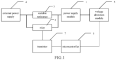
- FIG. 1 is a schematic diagram illustrating a circuit for suppressing a power supply starting surge provided in an embodiment of the present disclosure.
- the circuit for suppressing a power supply starting surge includes: a power supply module 1, a relay 2 and a variable resistance 3.
- the relay 2 is connected in parallel to the variable resistance 3 and then connected between an external power supply 4 and the power supply module 1.
- the circuit can have different startup instantaneous impulse currents (surge suppression value) and surge duration by setting a resistance value of the variable resistance 3.
- a resistance adjustment range of the variable resistance is 3 ⁇ -20 ⁇ .
- the startup instantaneous impulse currents of the circuit can be less than or equal to 73A. More preferably, the resistance adjustment range of the variable resistance is 5Q-10Q.
- the circuit for suppressing a power supply starting surge in the embodiment of the present disclosure further includes: a voltage detection module 5 and a microcontroller 6; in which an input terminal of the voltage detection module 5 is connected to an output terminal of the power supply module 1 for detecting an output voltage of the power supply module 1; an input terminal of the microcontroller 6 is connected to an output terminal of the voltage detection module 5, and the microcontroller 6 is configured to control whether to activate the relay 2 based on a detection result of the voltage detection module 5, thereby controlling whether the variable resistance 3 is connected to a power supply circuit from the external power supply 4 to the power supply module 1.
- the circuit for suppressing a power supply starting surge in the embodiment of the present disclosure further includes a transistor 7, of which an input terminal is connected to an output terminal of the microcontroller 6, and of which an output terminal is connected to an input terminal of the relay 2, in which the microcontroller 6 is configured to control turn-on and turn-off of the transistor 7 according to the detection result of the voltage detection module 5, thereby controlling whether to activate the relay 2, and whether the variable resistance 3 is connected to the power supply circuit from the external power supply 4 to the power supply module 1.
- the wording "activate” in “to activate the relay 2" in the embodiment of the present disclosure refers to driving the relay 2 to be turned on, whereas a state “being not activated” of the relay 2 can be understood that the relay 2 is in a turned-off state.
- circuit for suppressing a power supply starting surge provided in the embodiment of the present disclosure can be used in various high-power output devices (including but not limited to charging apparatuss for electric vehicles) to accomplish surge protection.
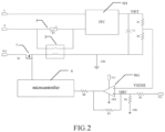
- the power supply module 1 may include: a PFC module 101 and a PFC capacitor C1 for power factor correction, in which an input terminal of the voltage detection module is connected to an output terminal of the PFC module 101 for detecting an output voltage of the PFC module 101; a first terminal of the PFC capacitor C1 is connected to the output terminal of the PFC module 101, a second terminal of the PFC capacitor C1 is connected to a ground terminal GND.
- the voltage of the external power supply is corrected by the PFC module 101 and the PFC capacitor C1, the power supply efficiency of the external power supply can be improved; when the divided voltage value of the output voltage of the PFC module is higher than a set voltage value (reference voltage value) by detecting the divided voltage value of the output voltage of the PFC module, the single-chip microcomputer drives the relay to be turned on, and the PFC module starts to output voltage normally.
- a set voltage value reference voltage value
- the voltage detection module 5 includes: a first resistance R1, a second resistance R2, and an operational amplifier 501, in which a first terminal of the first resistance R1 is connected to the output terminal of the PFC module, a second terminal of the first resistance R1 is connected to a first terminal of the second resistance R2, and a second terminal of the second resistance R2 is connected to a ground terminal GND; a terminal of the first resistance R1 connected to the second resistance R2 is connected to a negative input terminal of the operational amplifier 501, an output terminal of the operational amplifier 501 is connected to the microcontroller 6, and a positive input terminal of the operational amplifier 501 is connected to a reference voltage divider circuit.
- the operational amplifier 501 When VSENSE ⁇ VREF, the operational amplifier 501 outputs a high level, the single-chip microcomputer outputs a high level, the transistor is turned off, and the relay 2 is turned off; when VSENSE>VREF, when the operational amplifier 501 outputs a low level, the single-chip microcomputer outputs a low level, the transistor 7 is turned on and the relay 2 is turned on.
- the RT when the operational amplifier 501 outputs a high level, the relay 2 is turned off, and the PFC capacitor is charged through RT at the input voltage, so that the surge current is inversely proportional to the RT1 resistance, the RT with an appropriate resistance value can be chosen and the surge current can be controlled within an acceptable range; when the operational amplifier 501 outputs a low level, the relay 2 is turned on, and an impedance of a large current path can be reduced by short-circuiting the RT1, and the power system can achieve output at full power.
- a fifth resistance R5 is connected between the positive input terminal and the output terminal of the operational amplifier 501
- a sixth resistance R6 is connected between the output terminal of the operational amplifier 501 and the microprocessor 3, in which the fifth resistance R5 is a feedback resistance connected between an output pin of the operational amplifier 501 and a forward pin, which can eliminate zero drift; and the sixth resistance R6 can prevent the outputs from short-circuiting, in order to protect the operational amplifier 501.
- the transistor 7 of the present disclosure may be a triode, in which a base of the triode is connected to the microcontroller, and a collector of the triode is connected to the positive terminal of the external power supply, and an emitter of the triode is connected to the relay.
- the triode has a current amplification effect that the triode can control a great change in the collector current with a small change in the base current in essence.
- an embodiment of the present disclosure also provides a charging apparatus.
- the charging apparatus includes a circuit for suppressing a power supply starting surge according to any one of the above claims. Since the charging apparatus solves the problem on a similar principle to that of the circuit for suppressing a power supply starting surge, refer to the implementation of the circuit for suppressing a power supply starting surge for the implementation of the charging apparatus, where repetitions will not be described here anymore.
- an embodiment of the present disclosure also provides a method for suppressing a power supply starting surge, as mentioned in the embodiment below. Since this method solves the problem on a similar principle to that of the circuit for suppressing a power supply starting surge, refer to the implementation of the circuit for suppressing a power supply starting surge for the implementation of this method, where repetitions will not be described here anymore.
- the S302 can control, by the microcontroller, turn-on and turn-off of the transistor according to the detection result of the voltage detection module, thereby controlling whether to activate the relay, and whether the variable resistance is connected to a power supply circuit from the external power supply to the power supply module.
- the S302 can be specifically implemented in the steps as follows:
- an embodiment of the present disclosure also provides a computer-readable storage medium to solve the technical problem that in the existing power supply circuit, the relay is completely controlled by the hardware circuit, and the relay cannot function properly due to damages to any component in the hardware control circuit.
- the computer-readable storage medium stores a computer program for implementing the method for suppressing a power supply starting surge.
- the circuit, method for suppressing a power supply starting surge, the charging apparatus and the storage medium provided in the embodiments of the present disclosure connect the variable resistance in parallel to both ends of the relay, so that a power supply starting surge can be effectively suppressed, the power supply module is controlled to output an appropriate power supply voltage, and normal operation of components in the circuit can be protected.
Landscapes
- Engineering & Computer Science (AREA)
- Power Engineering (AREA)
- Transportation (AREA)
- Mechanical Engineering (AREA)
- Life Sciences & Earth Sciences (AREA)
- Sustainable Development (AREA)
- Sustainable Energy (AREA)
- Emergency Protection Circuit Devices (AREA)
- Direct Current Feeding And Distribution (AREA)
Applications Claiming Priority (2)
| Application Number | Priority Date | Filing Date | Title |
|---|---|---|---|
| CN202111014899.9A CN113765080A (zh) | 2021-08-31 | 2021-08-31 | 抑制电源启动浪涌的电路、方法、充电装置及存储介质 |
| PCT/CN2022/112468 WO2023029962A1 (zh) | 2021-08-31 | 2022-08-15 | 一种抑制电源启动浪涌的电路、方法、充电装置及存储介质 |
Publications (4)
| Publication Number | Publication Date |
|---|---|
| EP4398433A1 true EP4398433A1 (de) | 2024-07-10 |
| EP4398433A4 EP4398433A4 (de) | 2025-01-01 |
| EP4398433C0 EP4398433C0 (de) | 2026-01-14 |
| EP4398433B1 EP4398433B1 (de) | 2026-01-14 |
Family
ID=78792227
Family Applications (1)
| Application Number | Title | Priority Date | Filing Date |
|---|---|---|---|
| EP22863102.4A Active EP4398433B1 (de) | 2021-08-31 | 2022-08-15 | Schaltung und verfahren zur unterdrückung des stromversorgungsstartanstiegs, ladevorrichtung und speichermedium |
Country Status (7)
| Country | Link |
|---|---|
| US (1) | US20240380222A1 (de) |
| EP (1) | EP4398433B1 (de) |
| CN (1) | CN113765080A (de) |
| ES (1) | ES3062205T3 (de) |
| MX (1) | MX2024002631A (de) |
| PL (1) | PL4398433T3 (de) |
| WO (1) | WO2023029962A1 (de) |
Families Citing this family (3)
| Publication number | Priority date | Publication date | Assignee | Title |
|---|---|---|---|---|
| CN113765080A (zh) * | 2021-08-31 | 2021-12-07 | 长春捷翼汽车零部件有限公司 | 抑制电源启动浪涌的电路、方法、充电装置及存储介质 |
| CN115036896A (zh) * | 2022-05-20 | 2022-09-09 | 中航华东光电有限公司 | 浪涌电流控制电路及控制方法 |
| CN116599221A (zh) * | 2023-05-11 | 2023-08-15 | 中国电建集团北京勘测设计研究院有限公司 | 基于三维模型的电站发电机组监测控制系统及方法 |
Family Cites Families (10)
| Publication number | Priority date | Publication date | Assignee | Title |
|---|---|---|---|---|
| JP2856111B2 (ja) * | 1995-06-21 | 1999-02-10 | 日本電気株式会社 | 電源入力回路 |
| JP4644959B2 (ja) * | 2001-03-21 | 2011-03-09 | ソニー株式会社 | 電源装置 |
| JP4318662B2 (ja) * | 2005-04-22 | 2009-08-26 | シャープ株式会社 | 保護回路,電源装置 |
| CN201439976U (zh) * | 2009-05-25 | 2010-04-21 | 广东志高空调有限公司 | 变频空调浪涌电流的抑制电路 |
| CN202035203U (zh) * | 2011-04-15 | 2011-11-09 | 苏州市纽克斯照明有限公司 | 新型抗浪涌电流的电子镇流器 |
| CN105247773B (zh) * | 2013-01-09 | 2018-06-29 | 中国长城科技集团股份有限公司 | 一种具有浪涌抑制功能的全控桥式整流装置 |
| CN203406605U (zh) * | 2013-08-14 | 2014-01-22 | 南宁市跃龙科技有限公司 | 用于抑制浪涌电流的控制电路 |
| CN206498237U (zh) * | 2017-02-28 | 2017-09-15 | 深圳市快充王科技有限公司 | 一种直流充电桩电路 |
| CN108599543B (zh) * | 2018-04-18 | 2021-05-18 | 广东希塔变频技术有限公司 | 电源充电控制电路及电源充电控制方法 |
| CN113765080A (zh) * | 2021-08-31 | 2021-12-07 | 长春捷翼汽车零部件有限公司 | 抑制电源启动浪涌的电路、方法、充电装置及存储介质 |
-
2021
- 2021-08-31 CN CN202111014899.9A patent/CN113765080A/zh active Pending
-
2022
- 2022-08-15 US US18/688,241 patent/US20240380222A1/en active Pending
- 2022-08-15 EP EP22863102.4A patent/EP4398433B1/de active Active
- 2022-08-15 ES ES22863102T patent/ES3062205T3/es active Active
- 2022-08-15 WO PCT/CN2022/112468 patent/WO2023029962A1/zh not_active Ceased
- 2022-08-15 PL PL22863102.4T patent/PL4398433T3/pl unknown
- 2022-08-15 MX MX2024002631A patent/MX2024002631A/es unknown
Also Published As
| Publication number | Publication date |
|---|---|
| EP4398433C0 (de) | 2026-01-14 |
| EP4398433B1 (de) | 2026-01-14 |
| MX2024002631A (es) | 2024-04-30 |
| US20240380222A1 (en) | 2024-11-14 |
| CN113765080A (zh) | 2021-12-07 |
| PL4398433T3 (pl) | 2026-04-07 |
| WO2023029962A1 (zh) | 2023-03-09 |
| ES3062205T3 (en) | 2026-04-09 |
| EP4398433A4 (de) | 2025-01-01 |
Similar Documents
| Publication | Publication Date | Title |
|---|---|---|
| EP4398433A1 (de) | Schaltung und verfahren zur unterdrückung des stromversorgungsstartanstiegs, ladevorrichtung und speichermedium | |
| CN104704744B (zh) | 半导体驱动装置 | |
| CN113507200B (zh) | 一种功率变换器及其驱动电路 | |
| CN102842885B (zh) | 保护电路及具有保护电路的电子装置 | |
| CN103944148A (zh) | 一种t型三电平逆变器的保护方法、装置及逆变电路 | |
| JP2014087180A (ja) | スイッチング制御回路 | |
| CN111464007A (zh) | 全控型功率开关器件关断瞬间尖峰电压抑制方法和系统 | |
| CN104218531A (zh) | 短路保护电路及其短路保护方法 | |
| US9490794B1 (en) | Dynamic shutdown protection circuit | |
| CN120855236A (zh) | 一种适用于输入电压突变的电容浪涌电流抑制电路及方法 | |
| CN204068210U (zh) | 短路保护电路 | |
| CN105406701A (zh) | Igbt过压保护电路及方法 | |
| CN112491256B (zh) | 一种过流保护电路及电器设备 | |
| CN212695971U (zh) | 一种具有限流功能的短路保护模块 | |
| CN210201706U (zh) | 一种燃料电池汽车高速空压机用逆变器驱动电路 | |
| CN220325273U (zh) | 过压保护电路及电子设备 | |
| CN113437856B (zh) | 一种igbt驱动电路及控制方法 | |
| CN216751183U (zh) | 逆变器高安全性智能保护电路 | |
| CN210201707U (zh) | 电路结构及光伏空调系统 | |
| CN203491683U (zh) | 一种用于apf大功率igbt的短路保护电路 | |
| CN114465608A (zh) | Igbt保护电路及其保护方法、空调器和存储介质 | |
| CN222852006U (zh) | 一种大容性负载加电缓冲电路 | |
| CN215120095U (zh) | 一种电源电路 | |
| CN217445249U (zh) | 电源保护电路及电子设备 | |
| CN222827009U (zh) | 一种太阳能控制器大容性负载控制电路 |
Legal Events
| Date | Code | Title | Description |
|---|---|---|---|
| STAA | Information on the status of an ep patent application or granted ep patent |
Free format text: STATUS: THE INTERNATIONAL PUBLICATION HAS BEEN MADE |
|
| PUAI | Public reference made under article 153(3) epc to a published international application that has entered the european phase |
Free format text: ORIGINAL CODE: 0009012 |
|
| STAA | Information on the status of an ep patent application or granted ep patent |
Free format text: STATUS: REQUEST FOR EXAMINATION WAS MADE |
|
| 17P | Request for examination filed |
Effective date: 20240318 |
|
| AK | Designated contracting states |
Kind code of ref document: A1 Designated state(s): AL AT BE BG CH CY CZ DE DK EE ES FI FR GB GR HR HU IE IS IT LI LT LU LV MC MK MT NL NO PL PT RO RS SE SI SK SM TR |
|
| P01 | Opt-out of the competence of the unified patent court (upc) registered |
Free format text: CASE NUMBER: APP_43244/2024 Effective date: 20240724 |
|
| DAV | Request for validation of the european patent (deleted) | ||
| DAX | Request for extension of the european patent (deleted) | ||
| A4 | Supplementary search report drawn up and despatched |
Effective date: 20241202 |
|
| RIC1 | Information provided on ipc code assigned before grant |
Ipc: H01H 47/00 20060101ALN20241126BHEP Ipc: B60L 53/60 20190101ALN20241126BHEP Ipc: H02J 7/00 20060101ALI20241126BHEP Ipc: H02H 9/02 20060101ALI20241126BHEP Ipc: B60L 53/62 20190101ALI20241126BHEP Ipc: B60L 3/04 20060101ALI20241126BHEP Ipc: H02H 9/00 20060101AFI20241126BHEP |
|
| GRAP | Despatch of communication of intention to grant a patent |
Free format text: ORIGINAL CODE: EPIDOSNIGR1 |
|
| STAA | Information on the status of an ep patent application or granted ep patent |
Free format text: STATUS: GRANT OF PATENT IS INTENDED |
|
| RIC1 | Information provided on ipc code assigned before grant |
Ipc: H02H 9/00 20060101AFI20250806BHEP Ipc: B60L 3/04 20060101ALI20250806BHEP Ipc: B60L 53/62 20190101ALI20250806BHEP Ipc: H02H 9/02 20060101ALI20250806BHEP Ipc: H02J 7/00 20060101ALI20250806BHEP Ipc: B60L 53/60 20190101ALN20250806BHEP Ipc: H01H 47/00 20060101ALN20250806BHEP |
|
| INTG | Intention to grant announced |
Effective date: 20250822 |
|
| GRAS | Grant fee paid |
Free format text: ORIGINAL CODE: EPIDOSNIGR3 |
|
| GRAA | (expected) grant |
Free format text: ORIGINAL CODE: 0009210 |
|
| STAA | Information on the status of an ep patent application or granted ep patent |
Free format text: STATUS: THE PATENT HAS BEEN GRANTED |
|
| AK | Designated contracting states |
Kind code of ref document: B1 Designated state(s): AL AT BE BG CH CY CZ DE DK EE ES FI FR GB GR HR HU IE IS IT LI LT LU LV MC MK MT NL NO PL PT RO RS SE SI SK SM TR |
|
| REG | Reference to a national code |
Ref country code: CH Ref legal event code: F10 Free format text: ST27 STATUS EVENT CODE: U-0-0-F10-F00 (AS PROVIDED BY THE NATIONAL OFFICE) Effective date: 20260114 Ref country code: GB Ref legal event code: FG4D |
|
| REG | Reference to a national code |
Ref country code: DE Ref legal event code: R096 Ref document number: 602022028619 Country of ref document: DE |
|
| REG | Reference to a national code |
Ref country code: IE Ref legal event code: FG4D |
|
| P04 | Withdrawal of opt-out of the competence of the unified patent court (upc) registered |
Free format text: CASE NUMBER: APP_43244_1/2024 Effective date: 20260204 |
|
| U01 | Request for unitary effect filed |
Effective date: 20260130 |
|
| U07 | Unitary effect registered |
Designated state(s): AT BE BG DE DK EE FI FR IT LT LU LV MT NL PT RO SE SI Effective date: 20260204 |
|
| REG | Reference to a national code |
Ref country code: ES Ref legal event code: FG2A Ref document number: 3062205 Country of ref document: ES Kind code of ref document: T3 Effective date: 20260409 |