EP4398433A1 - Circuit and method for suppressing power supply starting surge, charging apparatus, and storage medium - Google Patents
Circuit and method for suppressing power supply starting surge, charging apparatus, and storage medium Download PDFInfo
- Publication number
- EP4398433A1 EP4398433A1 EP22863102.4A EP22863102A EP4398433A1 EP 4398433 A1 EP4398433 A1 EP 4398433A1 EP 22863102 A EP22863102 A EP 22863102A EP 4398433 A1 EP4398433 A1 EP 4398433A1
- Authority
- EP
- European Patent Office
- Prior art keywords
- power supply
- circuit
- terminal
- resistance
- suppressing
- Prior art date
- Legal status (The legal status is an assumption and is not a legal conclusion. Google has not performed a legal analysis and makes no representation as to the accuracy of the status listed.)
- Granted
Links
Images
Classifications
-
- H—ELECTRICITY
- H02—GENERATION; CONVERSION OR DISTRIBUTION OF ELECTRIC POWER
- H02H—EMERGENCY PROTECTIVE CIRCUIT ARRANGEMENTS
- H02H9/00—Emergency protective circuit arrangements for limiting excess current or voltage without disconnection
- H02H9/001—Emergency protective circuit arrangements for limiting excess current or voltage without disconnection limiting speed of change of electric quantities, e.g. soft switching on or off
-
- H—ELECTRICITY
- H02—GENERATION; CONVERSION OR DISTRIBUTION OF ELECTRIC POWER
- H02J—ELECTRIC POWER NETWORKS; CIRCUIT ARRANGEMENTS OR SYSTEMS FOR SUPPLYING OR DISTRIBUTING ELECTRIC POWER; SYSTEMS FOR STORING ELECTRIC ENERGY
- H02J7/00—Circuit arrangements for charging or discharging batteries or for supplying loads from batteries
- H02J7/60—Circuit arrangements for charging or discharging batteries or for supplying loads from batteries including safety or protection arrangements
- H02J7/62—Circuit arrangements for charging or discharging batteries or for supplying loads from batteries including safety or protection arrangements against overcurrent
-
- B—PERFORMING OPERATIONS; TRANSPORTING
- B60—VEHICLES IN GENERAL
- B60L—PROPULSION OF ELECTRICALLY-PROPELLED VEHICLES; SUPPLYING ELECTRIC POWER FOR AUXILIARY EQUIPMENT OF ELECTRICALLY-PROPELLED VEHICLES; ELECTRODYNAMIC BRAKE SYSTEMS FOR VEHICLES IN GENERAL; MAGNETIC SUSPENSION OR LEVITATION FOR VEHICLES; MONITORING OPERATING VARIABLES OF ELECTRICALLY-PROPELLED VEHICLES; ELECTRIC SAFETY DEVICES FOR ELECTRICALLY-PROPELLED VEHICLES
- B60L3/00—Electric devices on electrically-propelled vehicles for safety purposes; Monitoring operating variables, e.g. speed, deceleration or energy consumption
- B60L3/04—Cutting off the power supply under fault conditions
-
- B—PERFORMING OPERATIONS; TRANSPORTING
- B60—VEHICLES IN GENERAL
- B60L—PROPULSION OF ELECTRICALLY-PROPELLED VEHICLES; SUPPLYING ELECTRIC POWER FOR AUXILIARY EQUIPMENT OF ELECTRICALLY-PROPELLED VEHICLES; ELECTRODYNAMIC BRAKE SYSTEMS FOR VEHICLES IN GENERAL; MAGNETIC SUSPENSION OR LEVITATION FOR VEHICLES; MONITORING OPERATING VARIABLES OF ELECTRICALLY-PROPELLED VEHICLES; ELECTRIC SAFETY DEVICES FOR ELECTRICALLY-PROPELLED VEHICLES
- B60L53/00—Methods of charging batteries, specially adapted for electric vehicles; Charging stations or on-board charging equipment therefor; Exchange of energy storage elements in electric vehicles
-
- B—PERFORMING OPERATIONS; TRANSPORTING
- B60—VEHICLES IN GENERAL
- B60L—PROPULSION OF ELECTRICALLY-PROPELLED VEHICLES; SUPPLYING ELECTRIC POWER FOR AUXILIARY EQUIPMENT OF ELECTRICALLY-PROPELLED VEHICLES; ELECTRODYNAMIC BRAKE SYSTEMS FOR VEHICLES IN GENERAL; MAGNETIC SUSPENSION OR LEVITATION FOR VEHICLES; MONITORING OPERATING VARIABLES OF ELECTRICALLY-PROPELLED VEHICLES; ELECTRIC SAFETY DEVICES FOR ELECTRICALLY-PROPELLED VEHICLES
- B60L53/00—Methods of charging batteries, specially adapted for electric vehicles; Charging stations or on-board charging equipment therefor; Exchange of energy storage elements in electric vehicles
- B60L53/60—Monitoring or controlling charging stations
- B60L53/62—Monitoring or controlling charging stations in response to charging parameters, e.g. current, voltage or electrical charge
-
- H—ELECTRICITY
- H01—ELECTRIC ELEMENTS
- H01H—ELECTRIC SWITCHES; RELAYS; SELECTORS; EMERGENCY PROTECTIVE DEVICES
- H01H47/00—Circuit arrangements not adapted to a particular application of the relay and designed to obtain desired operating characteristics or to provide energising current
- H01H47/02—Circuit arrangements not adapted to a particular application of the relay and designed to obtain desired operating characteristics or to provide energising current for modifying the operation of the relay
-
- H—ELECTRICITY
- H02—GENERATION; CONVERSION OR DISTRIBUTION OF ELECTRIC POWER
- H02H—EMERGENCY PROTECTIVE CIRCUIT ARRANGEMENTS
- H02H9/00—Emergency protective circuit arrangements for limiting excess current or voltage without disconnection
- H02H9/001—Emergency protective circuit arrangements for limiting excess current or voltage without disconnection limiting speed of change of electric quantities, e.g. soft switching on or off
- H02H9/002—Emergency protective circuit arrangements for limiting excess current or voltage without disconnection limiting speed of change of electric quantities, e.g. soft switching on or off limiting inrush current on switching on of inductive loads subjected to remanence, e.g. transformers
-
- H—ELECTRICITY
- H02—GENERATION; CONVERSION OR DISTRIBUTION OF ELECTRIC POWER
- H02H—EMERGENCY PROTECTIVE CIRCUIT ARRANGEMENTS
- H02H9/00—Emergency protective circuit arrangements for limiting excess current or voltage without disconnection
- H02H9/005—Emergency protective circuit arrangements for limiting excess current or voltage without disconnection avoiding undesired transient conditions
-
- H—ELECTRICITY
- H02—GENERATION; CONVERSION OR DISTRIBUTION OF ELECTRIC POWER
- H02H—EMERGENCY PROTECTIVE CIRCUIT ARRANGEMENTS
- H02H9/00—Emergency protective circuit arrangements for limiting excess current or voltage without disconnection
- H02H9/02—Emergency protective circuit arrangements for limiting excess current or voltage without disconnection responsive to excess current
-
- H—ELECTRICITY
- H02—GENERATION; CONVERSION OR DISTRIBUTION OF ELECTRIC POWER
- H02J—ELECTRIC POWER NETWORKS; CIRCUIT ARRANGEMENTS OR SYSTEMS FOR SUPPLYING OR DISTRIBUTING ELECTRIC POWER; SYSTEMS FOR STORING ELECTRIC ENERGY
- H02J7/00—Circuit arrangements for charging or discharging batteries or for supplying loads from batteries
- H02J7/02—Circuit arrangements for charging or discharging batteries or for supplying loads from batteries for charging batteries from AC mains by converters
-
- H—ELECTRICITY
- H02—GENERATION; CONVERSION OR DISTRIBUTION OF ELECTRIC POWER
- H02J—ELECTRIC POWER NETWORKS; CIRCUIT ARRANGEMENTS OR SYSTEMS FOR SUPPLYING OR DISTRIBUTING ELECTRIC POWER; SYSTEMS FOR STORING ELECTRIC ENERGY
- H02J7/00—Circuit arrangements for charging or discharging batteries or for supplying loads from batteries
- H02J7/60—Circuit arrangements for charging or discharging batteries or for supplying loads from batteries including safety or protection arrangements
-
- H—ELECTRICITY
- H02—GENERATION; CONVERSION OR DISTRIBUTION OF ELECTRIC POWER
- H02J—ELECTRIC POWER NETWORKS; CIRCUIT ARRANGEMENTS OR SYSTEMS FOR SUPPLYING OR DISTRIBUTING ELECTRIC POWER; SYSTEMS FOR STORING ELECTRIC ENERGY
- H02J7/00—Circuit arrangements for charging or discharging batteries or for supplying loads from batteries
- H02J7/80—Circuit arrangements for charging or discharging batteries or for supplying loads from batteries including monitoring or indicating arrangements
-
- B—PERFORMING OPERATIONS; TRANSPORTING
- B60—VEHICLES IN GENERAL
- B60L—PROPULSION OF ELECTRICALLY-PROPELLED VEHICLES; SUPPLYING ELECTRIC POWER FOR AUXILIARY EQUIPMENT OF ELECTRICALLY-PROPELLED VEHICLES; ELECTRODYNAMIC BRAKE SYSTEMS FOR VEHICLES IN GENERAL; MAGNETIC SUSPENSION OR LEVITATION FOR VEHICLES; MONITORING OPERATING VARIABLES OF ELECTRICALLY-PROPELLED VEHICLES; ELECTRIC SAFETY DEVICES FOR ELECTRICALLY-PROPELLED VEHICLES
- B60L53/00—Methods of charging batteries, specially adapted for electric vehicles; Charging stations or on-board charging equipment therefor; Exchange of energy storage elements in electric vehicles
- B60L53/60—Monitoring or controlling charging stations
-
- H—ELECTRICITY
- H01—ELECTRIC ELEMENTS
- H01H—ELECTRIC SWITCHES; RELAYS; SELECTORS; EMERGENCY PROTECTIVE DEVICES
- H01H47/00—Circuit arrangements not adapted to a particular application of the relay and designed to obtain desired operating characteristics or to provide energising current
- H01H47/002—Monitoring or fail-safe circuits
-
- H—ELECTRICITY
- H02—GENERATION; CONVERSION OR DISTRIBUTION OF ELECTRIC POWER
- H02J—ELECTRIC POWER NETWORKS; CIRCUIT ARRANGEMENTS OR SYSTEMS FOR SUPPLYING OR DISTRIBUTING ELECTRIC POWER; SYSTEMS FOR STORING ELECTRIC ENERGY
- H02J2105/00—Networks for supplying or distributing electric power characterised by their spatial reach or by the load
- H02J2105/30—Networks for supplying or distributing electric power characterised by their spatial reach or by the load the load networks being external to vehicles, i.e. exchanging power with vehicles
- H02J2105/33—Networks for supplying or distributing electric power characterised by their spatial reach or by the load the load networks being external to vehicles, i.e. exchanging power with vehicles exchanging power with road vehicles
- H02J2105/37—Networks for supplying or distributing electric power characterised by their spatial reach or by the load the load networks being external to vehicles, i.e. exchanging power with vehicles exchanging power with road vehicles exchanging power with electric vehicles [EV] or with hybrid electric vehicles [HEV]
-
- Y—GENERAL TAGGING OF NEW TECHNOLOGICAL DEVELOPMENTS; GENERAL TAGGING OF CROSS-SECTIONAL TECHNOLOGIES SPANNING OVER SEVERAL SECTIONS OF THE IPC; TECHNICAL SUBJECTS COVERED BY FORMER USPC CROSS-REFERENCE ART COLLECTIONS [XRACs] AND DIGESTS
- Y02—TECHNOLOGIES OR APPLICATIONS FOR MITIGATION OR ADAPTATION AGAINST CLIMATE CHANGE
- Y02T—CLIMATE CHANGE MITIGATION TECHNOLOGIES RELATED TO TRANSPORTATION
- Y02T10/00—Road transport of goods or passengers
- Y02T10/60—Other road transportation technologies with climate change mitigation effect
- Y02T10/70—Energy storage systems for electromobility, e.g. batteries
-
- Y—GENERAL TAGGING OF NEW TECHNOLOGICAL DEVELOPMENTS; GENERAL TAGGING OF CROSS-SECTIONAL TECHNOLOGIES SPANNING OVER SEVERAL SECTIONS OF THE IPC; TECHNICAL SUBJECTS COVERED BY FORMER USPC CROSS-REFERENCE ART COLLECTIONS [XRACs] AND DIGESTS
- Y02—TECHNOLOGIES OR APPLICATIONS FOR MITIGATION OR ADAPTATION AGAINST CLIMATE CHANGE
- Y02T—CLIMATE CHANGE MITIGATION TECHNOLOGIES RELATED TO TRANSPORTATION
- Y02T10/00—Road transport of goods or passengers
- Y02T10/60—Other road transportation technologies with climate change mitigation effect
- Y02T10/7072—Electromobility specific charging systems or methods for batteries, ultracapacitors, supercapacitors or double-layer capacitors
-
- Y—GENERAL TAGGING OF NEW TECHNOLOGICAL DEVELOPMENTS; GENERAL TAGGING OF CROSS-SECTIONAL TECHNOLOGIES SPANNING OVER SEVERAL SECTIONS OF THE IPC; TECHNICAL SUBJECTS COVERED BY FORMER USPC CROSS-REFERENCE ART COLLECTIONS [XRACs] AND DIGESTS
- Y02—TECHNOLOGIES OR APPLICATIONS FOR MITIGATION OR ADAPTATION AGAINST CLIMATE CHANGE
- Y02T—CLIMATE CHANGE MITIGATION TECHNOLOGIES RELATED TO TRANSPORTATION
- Y02T90/00—Enabling technologies or technologies with a potential or indirect contribution to GHG emissions mitigation
- Y02T90/10—Technologies relating to charging of electric vehicles
- Y02T90/14—Plug-in electric vehicles
Definitions
- the present disclosure relates to the technical field of electric power, in particular to a circuit, a method for suppressing a power supply starting surge, a charging apparatus, and a storage medium.
- the safety of high-current power supply modules has attracted more attention, with the popularization of high-current charging technology for electric vehicles.
- the relay In the power supply circuit of the existing high-current power supply module, the relay is completely controlled by the hardware control circuit consisting of various components, the relay cannot work properly due to damages to any component in the hardware control circuit, which thus may lead to damages to the power supply module or other components.
- a high surge current is generated when a switch is powered on. Therefore, a circuit structure, which prevents a surge current, needs to be provided at an input terminal of the power supply.
- An embodiment of the present disclosure provides a circuit for suppressing a power supply starting surge to solve the technical problem that in the existing power supply circuit, the relay is completely controlled by the hardware circuit, and the relay cannot function properly due to damages to any component in the hardware control circuit.
- the circuit for suppressing a power supply starting surge includes: a power supply module, a relay and a variable resistance, and the relay is connected in parallel to the variable resistance and then connected between an external power supply and the power supply module.
- the circuit for suppressing a power supply starting surge in the embodiment of the present disclosure further includes: a voltage detection module and a microcontroller, in which an input terminal of the voltage detection module is connected to an output terminal of the power supply module for detecting an output voltage of the power supply module; an input terminal of the microcontroller is connected to an output terminal of the voltage detection module, and the microcontroller is configured to control whether to activate the relay based on a detection result of the voltage detection module, thereby controlling whether the variable resistance is connected to a power supply circuit from the external power supply to the power supply module.
- the circuit for suppressing a power supply starting surge in the embodiment of the present disclosure further includes a transistor, of which an input terminal is connected to an output terminal of the microcontroller, and of which an output terminal is connected to an input terminal of the relay, in which the microcontroller is configured to control turn-on and turn-off of the transistor according to the detection result of the voltage detection module, thereby controlling whether to activate the relay and whether the variable resistance is connected to the power supply circuit from the external power supply to the power supply module.
- the microcontroller is configured to: control the transistor to be turned on, drive the relay to be turned on, and short-circuit the variable resistance, so that the power supply module outputs a voltage of the external power supply at full power, in a case where the output voltage of the power supply module is higher than a reference voltage; and control the transistor to be turned off, and drive the relay to be turned off, so that an input voltage of the external power supply is input to the power supply module through the variable resistance, in a case where an output voltage of the power supply module is lower than the reference voltage.
- An embodiment of the present disclosure also provides a charging apparatus to solve the technical problem that in the existing power supply circuit, the relay is completely controlled by the hardware circuit, and the relay cannot function properly due to damages to any component in the hardware control circuit.
- the charging apparatus includes: any one of the circuits for suppressing a power supply starting surge.
- An embodiment of the present disclosure also provides a motor vehicle, including the charging apparatus.
- An embodiment of the present disclosure provides a method for suppressing a power supply starting surge to solve the technical problem that in the existing power supply circuit, the relay is completely controlled by the hardware circuit, the relay cannot function properly due to damages to any component in the hardware control circuit.
- the method for suppressing a power supply starting surge includes: detecting, by the voltage detection module, an output voltage of the power supply module; controlling, by the microcontroller, whether to activate the relay based on a detection result of the voltage detection module, and controlling whether the variable resistance is connected to a power supply circuit from the external power supply to the power supply module.
- the method for suppressing a power supply starting surge in the embodiment of the present disclosure further includes: controlling, by the microcontroller, turn-on and turn-off of the transistor according to the detection result of the voltage detection module, and controlling whether to activate the relay, and whether the variable resistance is connected to the power supply circuit from the external power supply to the power supply module.
- the method for suppressing a power supply starting surge in the embodiment of the present disclosure further includes: controlling, by the microcontroller, the transistor to be turned on, driving the relay to be turned on, and short-circuiting the variable resistance, so that the power supply module outputs a voltage of the external power supply at full power, in a case where an output voltage of the power supply module is higher than a reference voltage; and controlling, by the microcontroller, the transistor to be turned off, and driving the relay to be turned off, so that an input voltage of the external power supply is input through the variable resistance to the power supply module, in a case where the output voltage of the power supply module is lower than the reference voltage.
- An embodiment of the present disclosure also provides a computer-readable storage medium to solve the technical problem that in the existing power supply circuit, the relay is completely controlled by the hardware circuit, and the relay cannot function properly due to damages to any component in the hardware control circuit.
- the computer-readable storage medium stores a computer program for implementing the method for suppressing a power supply starting surge.
- An embodiment of the present disclosure also provides a motor vehicle, including the charging apparatus.
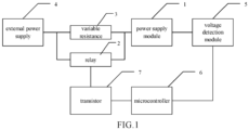
- FIG. 1 is a schematic diagram illustrating a circuit for suppressing a power supply starting surge provided in an embodiment of the present disclosure.
- the circuit for suppressing a power supply starting surge includes: a power supply module 1, a relay 2 and a variable resistance 3.
- the relay 2 is connected in parallel to the variable resistance 3 and then connected between an external power supply 4 and the power supply module 1.
- the circuit can have different startup instantaneous impulse currents (surge suppression value) and surge duration by setting a resistance value of the variable resistance 3.
- a resistance adjustment range of the variable resistance is 3 ⁇ -20 ⁇ .
- the startup instantaneous impulse currents of the circuit can be less than or equal to 73A. More preferably, the resistance adjustment range of the variable resistance is 5Q-10Q.
- the circuit for suppressing a power supply starting surge in the embodiment of the present disclosure further includes: a voltage detection module 5 and a microcontroller 6; in which an input terminal of the voltage detection module 5 is connected to an output terminal of the power supply module 1 for detecting an output voltage of the power supply module 1; an input terminal of the microcontroller 6 is connected to an output terminal of the voltage detection module 5, and the microcontroller 6 is configured to control whether to activate the relay 2 based on a detection result of the voltage detection module 5, thereby controlling whether the variable resistance 3 is connected to a power supply circuit from the external power supply 4 to the power supply module 1.
- the circuit for suppressing a power supply starting surge in the embodiment of the present disclosure further includes a transistor 7, of which an input terminal is connected to an output terminal of the microcontroller 6, and of which an output terminal is connected to an input terminal of the relay 2, in which the microcontroller 6 is configured to control turn-on and turn-off of the transistor 7 according to the detection result of the voltage detection module 5, thereby controlling whether to activate the relay 2, and whether the variable resistance 3 is connected to the power supply circuit from the external power supply 4 to the power supply module 1.
- the wording "activate” in “to activate the relay 2" in the embodiment of the present disclosure refers to driving the relay 2 to be turned on, whereas a state “being not activated” of the relay 2 can be understood that the relay 2 is in a turned-off state.
- circuit for suppressing a power supply starting surge provided in the embodiment of the present disclosure can be used in various high-power output devices (including but not limited to charging apparatuss for electric vehicles) to accomplish surge protection.
- the power supply module 1 may include: a PFC module 101 and a PFC capacitor C1 for power factor correction, in which an input terminal of the voltage detection module is connected to an output terminal of the PFC module 101 for detecting an output voltage of the PFC module 101; a first terminal of the PFC capacitor C1 is connected to the output terminal of the PFC module 101, a second terminal of the PFC capacitor C1 is connected to a ground terminal GND.
- the voltage of the external power supply is corrected by the PFC module 101 and the PFC capacitor C1, the power supply efficiency of the external power supply can be improved; when the divided voltage value of the output voltage of the PFC module is higher than a set voltage value (reference voltage value) by detecting the divided voltage value of the output voltage of the PFC module, the single-chip microcomputer drives the relay to be turned on, and the PFC module starts to output voltage normally.
- a set voltage value reference voltage value
- the voltage detection module 5 includes: a first resistance R1, a second resistance R2, and an operational amplifier 501, in which a first terminal of the first resistance R1 is connected to the output terminal of the PFC module, a second terminal of the first resistance R1 is connected to a first terminal of the second resistance R2, and a second terminal of the second resistance R2 is connected to a ground terminal GND; a terminal of the first resistance R1 connected to the second resistance R2 is connected to a negative input terminal of the operational amplifier 501, an output terminal of the operational amplifier 501 is connected to the microcontroller 6, and a positive input terminal of the operational amplifier 501 is connected to a reference voltage divider circuit.
- the operational amplifier 501 When VSENSE ⁇ VREF, the operational amplifier 501 outputs a high level, the single-chip microcomputer outputs a high level, the transistor is turned off, and the relay 2 is turned off; when VSENSE>VREF, when the operational amplifier 501 outputs a low level, the single-chip microcomputer outputs a low level, the transistor 7 is turned on and the relay 2 is turned on.
- the RT when the operational amplifier 501 outputs a high level, the relay 2 is turned off, and the PFC capacitor is charged through RT at the input voltage, so that the surge current is inversely proportional to the RT1 resistance, the RT with an appropriate resistance value can be chosen and the surge current can be controlled within an acceptable range; when the operational amplifier 501 outputs a low level, the relay 2 is turned on, and an impedance of a large current path can be reduced by short-circuiting the RT1, and the power system can achieve output at full power.
- a fifth resistance R5 is connected between the positive input terminal and the output terminal of the operational amplifier 501
- a sixth resistance R6 is connected between the output terminal of the operational amplifier 501 and the microprocessor 3, in which the fifth resistance R5 is a feedback resistance connected between an output pin of the operational amplifier 501 and a forward pin, which can eliminate zero drift; and the sixth resistance R6 can prevent the outputs from short-circuiting, in order to protect the operational amplifier 501.
- the transistor 7 of the present disclosure may be a triode, in which a base of the triode is connected to the microcontroller, and a collector of the triode is connected to the positive terminal of the external power supply, and an emitter of the triode is connected to the relay.
- the triode has a current amplification effect that the triode can control a great change in the collector current with a small change in the base current in essence.
- an embodiment of the present disclosure also provides a charging apparatus.
- the charging apparatus includes a circuit for suppressing a power supply starting surge according to any one of the above claims. Since the charging apparatus solves the problem on a similar principle to that of the circuit for suppressing a power supply starting surge, refer to the implementation of the circuit for suppressing a power supply starting surge for the implementation of the charging apparatus, where repetitions will not be described here anymore.
- an embodiment of the present disclosure also provides a method for suppressing a power supply starting surge, as mentioned in the embodiment below. Since this method solves the problem on a similar principle to that of the circuit for suppressing a power supply starting surge, refer to the implementation of the circuit for suppressing a power supply starting surge for the implementation of this method, where repetitions will not be described here anymore.
- the S302 can control, by the microcontroller, turn-on and turn-off of the transistor according to the detection result of the voltage detection module, thereby controlling whether to activate the relay, and whether the variable resistance is connected to a power supply circuit from the external power supply to the power supply module.
- the S302 can be specifically implemented in the steps as follows:
- an embodiment of the present disclosure also provides a computer-readable storage medium to solve the technical problem that in the existing power supply circuit, the relay is completely controlled by the hardware circuit, and the relay cannot function properly due to damages to any component in the hardware control circuit.
- the computer-readable storage medium stores a computer program for implementing the method for suppressing a power supply starting surge.
- the circuit, method for suppressing a power supply starting surge, the charging apparatus and the storage medium provided in the embodiments of the present disclosure connect the variable resistance in parallel to both ends of the relay, so that a power supply starting surge can be effectively suppressed, the power supply module is controlled to output an appropriate power supply voltage, and normal operation of components in the circuit can be protected.
Landscapes
- Engineering & Computer Science (AREA)
- Power Engineering (AREA)
- Transportation (AREA)
- Mechanical Engineering (AREA)
- Life Sciences & Earth Sciences (AREA)
- Sustainable Development (AREA)
- Sustainable Energy (AREA)
- Emergency Protection Circuit Devices (AREA)
- Direct Current Feeding And Distribution (AREA)
Abstract
Description
- The present disclosure claims priority to
Chinese Patent Application No. 202111014899.9, entitled "CIRCUIT AND METHOD FOR SUPPRESSING POWER SUPPLY STARTING SURGE, CHARGING APPARATUS, AND STORAGE MEDIUM" as filed on August 31, 2021 - The present disclosure relates to the technical field of electric power, in particular to a circuit, a method for suppressing a power supply starting surge, a charging apparatus, and a storage medium.
- The safety of high-current power supply modules has attracted more attention, with the popularization of high-current charging technology for electric vehicles. In the power supply circuit of the existing high-current power supply module, the relay is completely controlled by the hardware control circuit consisting of various components, the relay cannot work properly due to damages to any component in the hardware control circuit, which thus may lead to damages to the power supply module or other components. Moreover, a high surge current is generated when a switch is powered on. Therefore, a circuit structure, which prevents a surge current, needs to be provided at an input terminal of the power supply.
- Therefore, how to avoid direct damages to the power supply module or other components due to relay failure and how to suppress the surge current have become problems to be urgently solved by those skilled in the art.
- An embodiment of the present disclosure provides a circuit for suppressing a power supply starting surge to solve the technical problem that in the existing power supply circuit, the relay is completely controlled by the hardware circuit, and the relay cannot function properly due to damages to any component in the hardware control circuit. The circuit for suppressing a power supply starting surge includes: a power supply module, a relay and a variable resistance, and the relay is connected in parallel to the variable resistance and then connected between an external power supply and the power supply module.
- Further, the circuit for suppressing a power supply starting surge in the embodiment of the present disclosure further includes: a voltage detection module and a microcontroller, in which an input terminal of the voltage detection module is connected to an output terminal of the power supply module for detecting an output voltage of the power supply module; an input terminal of the microcontroller is connected to an output terminal of the voltage detection module, and the microcontroller is configured to control whether to activate the relay based on a detection result of the voltage detection module, thereby controlling whether the variable resistance is connected to a power supply circuit from the external power supply to the power supply module.
- Furthermore, the circuit for suppressing a power supply starting surge in the embodiment of the present disclosure further includes a transistor, of which an input terminal is connected to an output terminal of the microcontroller, and of which an output terminal is connected to an input terminal of the relay, in which the microcontroller is configured to control turn-on and turn-off of the transistor according to the detection result of the voltage detection module, thereby controlling whether to activate the relay and whether the variable resistance is connected to the power supply circuit from the external power supply to the power supply module.
- Furthermore, the microcontroller is configured to: control the transistor to be turned on, drive the relay to be turned on, and short-circuit the variable resistance, so that the power supply module outputs a voltage of the external power supply at full power, in a case where the output voltage of the power supply module is higher than a reference voltage; and control the transistor to be turned off, and drive the relay to be turned off, so that an input voltage of the external power supply is input to the power supply module through the variable resistance, in a case where an output voltage of the power supply module is lower than the reference voltage.
- An embodiment of the present disclosure also provides a charging apparatus to solve the technical problem that in the existing power supply circuit, the relay is completely controlled by the hardware circuit, and the relay cannot function properly due to damages to any component in the hardware control circuit. The charging apparatus includes: any one of the circuits for suppressing a power supply starting surge.
- An embodiment of the present disclosure also provides a motor vehicle, including the charging apparatus.
- An embodiment of the present disclosure provides a method for suppressing a power supply starting surge to solve the technical problem that in the existing power supply circuit, the relay is completely controlled by the hardware circuit, the relay cannot function properly due to damages to any component in the hardware control circuit. The method for suppressing a power supply starting surge includes: detecting, by the voltage detection module, an output voltage of the power supply module; controlling, by the microcontroller, whether to activate the relay based on a detection result of the voltage detection module, and controlling whether the variable resistance is connected to a power supply circuit from the external power supply to the power supply module.
- Further, the method for suppressing a power supply starting surge in the embodiment of the present disclosure further includes: controlling, by the microcontroller, turn-on and turn-off of the transistor according to the detection result of the voltage detection module, and controlling whether to activate the relay, and whether the variable resistance is connected to the power supply circuit from the external power supply to the power supply module.
- Furthermore, the method for suppressing a power supply starting surge in the embodiment of the present disclosure further includes: controlling, by the microcontroller, the transistor to be turned on, driving the relay to be turned on, and short-circuiting the variable resistance, so that the power supply module outputs a voltage of the external power supply at full power, in a case where an output voltage of the power supply module is higher than a reference voltage; and controlling, by the microcontroller, the transistor to be turned off, and driving the relay to be turned off, so that an input voltage of the external power supply is input through the variable resistance to the power supply module, in a case where the output voltage of the power supply module is lower than the reference voltage.
- An embodiment of the present disclosure also provides a computer-readable storage medium to solve the technical problem that in the existing power supply circuit, the relay is completely controlled by the hardware circuit, and the relay cannot function properly due to damages to any component in the hardware control circuit. The computer-readable storage medium stores a computer program for implementing the method for suppressing a power supply starting surge.
- An embodiment of the present disclosure also provides a motor vehicle, including the charging apparatus.
- The circuit, method for suppressing a power supply starting surge, the charging apparatus, the storage medium, and the motor vehicle provided in the embodiments of the present disclosure connect a variable resistance in parallel to both ends of the relay, so that a power supply starting surge current can be effectively suppressed, and the power supply module is controlled to output an appropriate power supply voltage, and thus normal operation of components in the circuit can be protected.
- Further, based on a combination of software control and hardware circuits, according to the voltage detection result, turn-on and turn-off of the relay are controlled by the microcontroller and the transistor, the number of components required for relay control is reduced, and the probability that the relay does not function properly can be reduced, so as to avoid damages to the power supply module or other components in the circuit due to relay failure. Applying the circuit for suppressing a power supply starting surge provided in the embodiment of the present disclosure to the charging apparatus can not only suppress the surge current caused by power startup, but also improve the stability and durability of a surge protection circuit of the charging apparatus.
- In order to more clearly demonstrate the technical solutions in the embodiments of the present disclosure or the prior art, drawings that need to be used in the description in the embodiments or the prior art will be simply introduced below. Obviously, the drawings in the description below are only some embodiments of the present disclosure, and other drawings may also be obtained by those skilled in the art based on these drawings without creative efforts.
-
FIG. 1 is a schematic block diagram illustrating a circuit for suppressing a power supply starting surge provided in an embodiment of the present disclosure; -
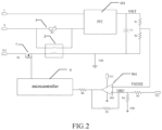
FIG. 2 is a schematic diagram illustrating a circuit for suppressing a power supply starting surge provided in an embodiment of the present disclosure; -
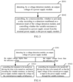
FIG. 3 is a flowchart illustrating a method for suppressing a power supply starting surge provided in an embodiment of the present disclosure; and -
FIG. 4 is a flowchart illustrating an alternative method for suppressing a power supply starting surge provided in an embodiment of the present disclosure. - In order to more clearly describe the objective, technical solutions and advantages in the embodiments of the present disclosure, the drawings to be used in the description of the embodiments will be introduced in further detail below. The schematic embodiments and descriptions of the present disclosure are used herein to demonstrate the present disclosure, but are not intended to be a limitation of the present disclosure.
- An embodiment of the present disclosure provides a circuit for suppressing a power supply starting surge.
FIG. 1 is a schematic diagram illustrating a circuit for suppressing a power supply starting surge provided in an embodiment of the present disclosure. As illustrated inFIG. 1 , the circuit for suppressing a power supply starting surge includes: a power supply module 1, arelay 2 and a variable resistance 3. Therelay 2 is connected in parallel to the variable resistance 3 and then connected between an external power supply 4 and the power supply module 1. - It should be noted that in the circuit for suppressing a power supply starting surge provided in the embodiment of the present disclosure, the circuit can have different startup instantaneous impulse currents (surge suppression value) and surge duration by setting a resistance value of the variable resistance 3. In an embodiment, a resistance adjustment range of the variable resistance is 3Ω-20Ω. In an embodiment, if the resistance adjustment range of the variable resistance is 3Q-20Q, the startup instantaneous impulse currents of the circuit can be less than or equal to 73A. More preferably, the resistance adjustment range of the variable resistance is 5Q-10Q. In an embodiment, if the resistance adjustment range of the variable resistance is 5Q-10Q, the startup instantaneous impulse currents of the circuit can be less than or equal to 44A, and the surge duration of the circuit can be less than or equal to 4s. Surge protection can be achieved by limiting the power supply starting surge current value and duration within a certain range. More specifically, as can be seen, the present disclosure does not limit the resistance value of the variable resistance 3 in the adjustment process. In various embodiments, the resistance value of the variable resistance 3 can be 5Q, 652, 7Q...10Q; the corresponding surge suppression value is 44A, 36.6A, 31.4A...22A, that is, a product of the resistance value of the variable resistor 3 and the surge suppression value is a mains voltage of 220V.
- In order to realize the software control of the
relay 2, in an embodiment, the circuit for suppressing a power supply starting surge in the embodiment of the present disclosure further includes: avoltage detection module 5 and amicrocontroller 6; in which an input terminal of thevoltage detection module 5 is connected to an output terminal of the power supply module 1 for detecting an output voltage of the power supply module 1; an input terminal of themicrocontroller 6 is connected to an output terminal of thevoltage detection module 5, and themicrocontroller 6 is configured to control whether to activate therelay 2 based on a detection result of thevoltage detection module 5, thereby controlling whether the variable resistance 3 is connected to a power supply circuit from the external power supply 4 to the power supply module 1. - Further, in order to better control the
relay 2, in an embodiment, the circuit for suppressing a power supply starting surge in the embodiment of the present disclosure further includes atransistor 7, of which an input terminal is connected to an output terminal of themicrocontroller 6, and of which an output terminal is connected to an input terminal of therelay 2, in which themicrocontroller 6 is configured to control turn-on and turn-off of thetransistor 7 according to the detection result of thevoltage detection module 5, thereby controlling whether to activate therelay 2, and whether the variable resistance 3 is connected to the power supply circuit from the external power supply 4 to the power supply module 1. - It should be noted that the wording "activate" in "to activate the
relay 2" in the embodiment of the present disclosure refers to driving therelay 2 to be turned on, whereas a state "being not activated" of therelay 2 can be understood that therelay 2 is in a turned-off state. - According to the voltage detection result of the
voltage detection module 5, themicrocontroller 6 in the embodiment of the present disclosure controls turn-on and turn-off of therelay 2 by themicrocontroller 6 and thetransistor 7, so as to ensure the normal operation of the relay to avoid direct damages to the power supply module and other components in the circuit. - Alternatively, the
microcontroller 6 in the embodiment of the present disclosure adopts a single-chip microcomputer. - In an embodiment, the
microcontroller 6 in the embodiment of the present disclosure can be configured to control thetransistor 7 to be turned on, drive therelay 2 to be turned on and short-circuit the variable resistance 3, so that the power supply module 1 outputs a voltage of the external power supply 4 at full power, in a case where the output voltage of the power supply module 1 is higher than a reference voltage; control thetransistor 7 to be turned off, and drive therelay 2 to be turned off, so that an input voltage of the external power supply 4 is input to the power supply module 1 through the variable resistance 3, in a case where an output voltage of the power supply module 1 is lower than the reference voltage. - In the embodiment, in the case where the output voltage of the power supply module 1 is higher than the reference voltage, it indicates that the power supply module 1 is in an operating state of charging outwards, in this case, the variable resistance 3 needs to be short-circuited, so that the power supply module 1 can output the voltage of the external power supply 4 at full power, and improve the charging efficiency of the power supply module 1; in the case where the output voltage of the power supply module 1 is lower than the reference voltage, it indicates that the power supply module 1 stops charging outwards, in this case, the variable resistance 3 needs to be connected, so that the input voltage of the external power supply 4 is input to the power supply module 1 through the variable resistance 3, so that the power supply module 1 outputs an appropriate voltage, in order to prevent various components in the power supply module 1 from being damaged.
- It should be noted that the circuit for suppressing a power supply starting surge provided in the embodiment of the present disclosure can be used in various high-power output devices (including but not limited to charging apparatuss for electric vehicles) to accomplish surge protection.
- Therefore, in an embodiment, the circuit for suppressing a power supply starting surge provided in the embodiment of the present disclosure can be placed at a front end of the charging apparatus, and between the external power supply and the charging apparatus, in order to protect the charging apparatus from being damaged.
- Next, referring to
FIG. 2 , in the circuit for suppressing a power supply starting surge according to the embodiment of the present disclosure, the power supply module 1 may include: aPFC module 101 and a PFC capacitor C1 for power factor correction, in which an input terminal of the voltage detection module is connected to an output terminal of thePFC module 101 for detecting an output voltage of thePFC module 101; a first terminal of the PFC capacitor C1 is connected to the output terminal of thePFC module 101, a second terminal of the PFC capacitor C1 is connected to a ground terminal GND. In the embodiment of the present disclosure, the voltage of the external power supply is corrected by thePFC module 101 and the PFC capacitor C1, the power supply efficiency of the external power supply can be improved; when the divided voltage value of the output voltage of the PFC module is higher than a set voltage value (reference voltage value) by detecting the divided voltage value of the output voltage of the PFC module, the single-chip microcomputer drives the relay to be turned on, and the PFC module starts to output voltage normally. - In an embodiment, as illustrated in
FIG. 2 , in the circuit for suppressing a power supply starting surge in the embodiment of the present disclosure, thevoltage detection module 5 includes: a first resistance R1, a second resistance R2, and anoperational amplifier 501, in which a first terminal of the first resistance R1 is connected to the output terminal of the PFC module, a second terminal of the first resistance R1 is connected to a first terminal of the second resistance R2, and a second terminal of the second resistance R2 is connected to a ground terminal GND; a terminal of the first resistance R1 connected to the second resistance R2 is connected to a negative input terminal of theoperational amplifier 501, an output terminal of theoperational amplifier 501 is connected to themicrocontroller 6, and a positive input terminal of theoperational amplifier 501 is connected to a reference voltage divider circuit. - Alternatively, the number of the first resistance R1 and the second resistance R2 may be one or more, in order to guarantee the accuracy of the collected voltage value.
- As illustrated in
FIG. 2 , the reference voltage divider circuit is used to provide a reference voltage (inFIG. 2 , VREF refers to the reference voltage and VSENSE refers to the output voltage detected by the voltage detection module). Specifically, the reference voltage divider circuit includes: a third resistance R3 and a fourth resistance R4, in which a first terminal of the third resistance R3 is connected to a positive terminal VCC of the external power supply, a second terminal of the third resistance R3 is connected to a first terminal of the fourth resistance R4, a second terminal of the fourth resistance R4 is connected to the ground terminal, and a terminal of the third resistance R3 connected to the fourth resistance R4 is connected to the positive input terminal of theoperational amplifier 501. In the embodiment of the present disclosure, the terminal of the third resistance R3 connected to the fourth resistance R4 is connected to the negative input terminal of the operational amplifier to form a voltage detection circuit. - In this embodiment, VREF=VCC×R4/(R3+R4); VSENSE=VOUT×R2/(R1+R2).
- The single-chip microcomputer in the embodiment of the present disclosure is connected to the gate of the transistor, and VCC is connected to the drain of the
transistor 7. In an embodiment, the single-chip microcomputer is configured such that theoperational amplifier 501 outputs a high level, and the single-chip microcomputer outputs a high level; theoperational amplifier 501 outputs a low level, and the single-chip microcomputer outputs a low level. Certainly, in other embodiments, the single-chip microcomputer can be configured such that theoperational amplifier 501 outputs a high level, and the single-chip microcomputer outputs a low level; theoperational amplifier 501 outputs a low level, and the single-chip microcomputer outputs a high level. - When VSENSE<VREF, the
operational amplifier 501 outputs a high level, the single-chip microcomputer outputs a high level, the transistor is turned off, and therelay 2 is turned off; when VSENSE>VREF, when theoperational amplifier 501 outputs a low level, the single-chip microcomputer outputs a low level, thetransistor 7 is turned on and therelay 2 is turned on. That is, when theoperational amplifier 501 outputs a high level, therelay 2 is turned off, and the PFC capacitor is charged through RT at the input voltage, so that the surge current is inversely proportional to the RT1 resistance, the RT with an appropriate resistance value can be chosen and the surge current can be controlled within an acceptable range; when theoperational amplifier 501 outputs a low level, therelay 2 is turned on, and an impedance of a large current path can be reduced by short-circuiting the RT1, and the power system can achieve output at full power. - Further, a fifth resistance R5 is connected between the positive input terminal and the output terminal of the
operational amplifier 501, and a sixth resistance R6 is connected between the output terminal of theoperational amplifier 501 and the microprocessor 3, in which the fifth resistance R5 is a feedback resistance connected between an output pin of theoperational amplifier 501 and a forward pin, which can eliminate zero drift; and the sixth resistance R6 can prevent the outputs from short-circuiting, in order to protect theoperational amplifier 501. - In an embodiment, the
transistor 7 of the present disclosure can be a field effect transistor, in which a gate of the field effect transistor is connected to the microcontroller, and a drain of the field effect transistor is connected to the positive terminal of the external power supply, and the source of the field effect transistor is connected to the relay. The field effect transistor has advantages such as high input resistance, low noise, low power consumption, large dynamic range, easy integration, no secondary breakdown phenomenon, and wide safe working area. - In another embodiment, the
transistor 7 of the present disclosure may be a triode, in which a base of the triode is connected to the microcontroller, and a collector of the triode is connected to the positive terminal of the external power supply, and an emitter of the triode is connected to the relay. The triode has a current amplification effect that the triode can control a great change in the collector current with a small change in the base current in essence. - It should be noted that the field effect transistor and the triode in the embodiment of the present disclosure can be replaced without changing the wiring method, and the specific parameters are selected according to the
relay 2. - Based on the same inventive concept, an embodiment of the present disclosure also provides a charging apparatus. The charging apparatus includes a circuit for suppressing a power supply starting surge according to any one of the above claims. Since the charging apparatus solves the problem on a similar principle to that of the circuit for suppressing a power supply starting surge, refer to the implementation of the circuit for suppressing a power supply starting surge for the implementation of the charging apparatus, where repetitions will not be described here anymore.
- It should be noted that the charging apparatus provided in the embodiment of the present disclosure refers to a high-power charging apparatus, which may be but not limited to a charging apparatus for an electric vehicle.
- Based on the same inventive concept, an embodiment of the present disclosure also provides a method for suppressing a power supply starting surge, as mentioned in the embodiment below. Since this method solves the problem on a similar principle to that of the circuit for suppressing a power supply starting surge, refer to the implementation of the circuit for suppressing a power supply starting surge for the implementation of this method, where repetitions will not be described here anymore.
-
FIG. 3 is a flowchart illustrating a method for suppressing a power supply starting surge provided in an embodiment of the present disclosure. As illustrated inFIG. 3 , the method includes the steps of: - S301, detecting, by a voltage detection module, an output voltage of a power supply module; and
- S302, controlling, by a microcontroller, whether to activate a relay based on a detection result of the voltage detection module, and controlling whether the variable resistance is connected to a power supply circuit from the external power supply to the power supply module.
- In an embodiment, the S302 can control, by the microcontroller, turn-on and turn-off of the transistor according to the detection result of the voltage detection module, thereby controlling whether to activate the relay, and whether the variable resistance is connected to a power supply circuit from the external power supply to the power supply module.
- Further, in an embodiment, as illustrated in
FIG. 4 , the S302 can be specifically implemented in the steps as follows: - S3021, controlling the transistor to be turned on, driving the relay to be turned on, and short-circuiting the variable resistance, so that the power supply module outputs the voltage of the external power supply at full power, in a case where the output voltage of the power supply module is higher than the reference voltage; and
- S3022, controlling the transistor to be turned off, driving the relay to be turned off, so that the input voltage of the external power supply is input to the power supply module through the variable resistance, in a case where the output voltage of the power supply module is lower than the reference voltage.
- Based on the same inventive concept, an embodiment of the present disclosure also provides a computer-readable storage medium to solve the technical problem that in the existing power supply circuit, the relay is completely controlled by the hardware circuit, and the relay cannot function properly due to damages to any component in the hardware control circuit. The computer-readable storage medium stores a computer program for implementing the method for suppressing a power supply starting surge.
- Based on the same inventive concept, an embodiment of the present disclosure also provides a motor vehicle, including the charging apparatus in the embodiment.
- To sum up, the circuit, method for suppressing a power supply starting surge, the charging apparatus and the storage medium provided in the embodiments of the present disclosure connect the variable resistance in parallel to both ends of the relay, so that a power supply starting surge can be effectively suppressed, the power supply module is controlled to output an appropriate power supply voltage, and normal operation of components in the circuit can be protected.
- Further, based on a combination of software control and hardware circuits, according to the voltage detection result, turn-on and turn-off of the relay are controlled by the microcontroller and transistor, the number of components required for relay control is reduced, and the probability that the relay does not function properly can be reduced, so as to avoid damages to the power supply module or other components in the circuit due to relay failure. Applying the circuit for suppressing a power supply starting surge provided in the embodiment of the present disclosure to the charging apparatus can improve the stability and durability of a surge protection circuit of the charging apparatus.
- Those skilled in the art shall understand that the embodiments of the present disclosure may be provided as a method, a system, or a computer program product. Accordingly, the present disclosure can take the form of an embodiment of hardware alone, an embodiment of software alone, or an embodiment combining software with hardware. Further, the present disclosure may take the form of a computer program product embodied on one or more computer-usable storage media (including but not limited to a magnetic-disk memory, a CD-ROM, an optical memory) having a computer-usable program code.
- The present disclosure is described with reference to a flowchart and/or a block diagram of method, device (system), and computer program product according to embodiments of the present disclosure. It should be understood that each procedure and/or block in the flowchart and/or block diagram, and a combination of procedures and/or blocks in the flowchart and/or block diagram can be realized by computer program instructions. These computer program instructions may be provided to a general-purpose computer, a special-purpose computer, an embedded processor, or a processor of other programmable data processing equipment to produce a machine such that the instructions executed by the computer or the processor of other programmable data processing equipment produce a device for realizing the functions specified in one or more procedures of the flowchart and/or one or more blocks of the block diagram.
- These computer program instructions may also be stored in a computer-readable memory capable of directing a computer or other programmable data processing equipment to function in a specific manner, such that the instructions stored in the computer-readable memory produce an article of manufacture including an instruction device that realizes functions specified in one or more procedures of the flowchart and/or one or more blocks of the block diagram.
- These computer program instructions can also be loaded onto a computer or other programmable data processing equipment, such that a series of operational steps are performed on the computer or other programmable equipment to produce a computer-implemented process, thus the instructions executed on the computer or other programmable equipment provide steps for implementing the functions specified in one or more procedures of the flowchart and/or one or more blocks of the block diagram.
- The embodiments described above have further described the objective, technical solutions and advantageous effects of the present disclosure in detail. It should be understood that those described above are just the embodiments of the present disclosure, rather than limitations thereto. Any amendment, equivalent substitution, improvement within the spirit and principle of the present disclosure should fall within the protection scope of the present disclosure.
Claims (20)
- A circuit for suppressing a power supply starting surge, including: a power supply module, a relay and a variable resistance, wherein the relay is connected in parallel to the variable resistance and then connected between an external power supply and the power supply module.
- The circuit for suppressing a power supply starting surge according to claim 1, further including: a voltage detection module and a microcontroller, wherein an input terminal of the voltage detection module is connected to an output terminal of the power supply module for detecting an output voltage of the power supply module; an input terminal of the microcontroller is connected to an output terminal of the voltage detection module, and the microcontroller is configured to control whether to activate the relay based on a detection result of the voltage detection module, thereby controlling whether the variable resistance is connected to a power supply circuit from the external power supply to the power supply module.
- The circuit for suppressing a power supply starting surge according to claim 2, further including: a transistor, of which an input terminal is connected to an output terminal of the microcontroller, and of which an output terminal is connected to an input terminal of the relay, wherein the microcontroller is configured to control turn-on and turn-off of the transistor based on the detection result of the voltage detection module, thereby controlling whether to activate the relay and whether the variable resistance is connected to the power supply circuit from the external power supply to the power supply module.
- The circuit for suppressing a power supply starting surge according to claim 3, wherein the microcontroller is configured to: control the transistor to be turned on, drive the relay to be turned on, and short-circuit the variable resistance, so that the power supply module outputs a voltage of the external power supply at full power, in a case where the output voltage of the power supply module is higher than a reference voltage; and control the transistor to be turned off and drive the relay to be turned off, so that an input voltage of the external power supply is input to the power supply module through the variable resistance, in a case where the output voltage of the power supply module is lower than the reference voltage.
- The circuit for suppressing a power supply starting surge according to claim 2, wherein the power supply module includes: a PFC module and a PFC capacitor for power factor correction, in which an input terminal of the voltage detection module is connected to an output terminal of the PFC module for detecting an output voltage of the PFC module; a first terminal of the PFC capacitor is connected to the output terminal of the PFC module, and a second terminal of the PFC capacitor is connected to a ground terminal.
- The circuit for suppressing a power supply starting surge according to claim 5, wherein the voltage detection module includes: a first resistance, a second resistance, and an operational amplifier, in which a first terminal of the first resistance is connected to the output terminal of the PFC module, a second terminal of the first resistance is connected to a first terminal of the second resistance, and a second terminal of the second resistance is connected to the ground terminal; a terminal of the first resistance connected to the second resistance is connected to a negative input terminal of the operational amplifier, an output terminal of the operational amplifier is connected to the microcontroller, and a positive input terminal of the operational amplifier is connected to a reference voltage divider circuit, in which the reference voltage divider circuit is used to provide a reference voltage.
- The circuit for suppressing a power supply starting surge according to claim 6, wherein the reference voltage divider circuit includes: a third resistance and a fourth resistance, in which a first terminal of the third resistance is connected to a positive terminal of the external power supply, a second terminal of the third resistance is connected to a first terminal of the fourth resistance, a second terminal of the fourth resistance is connected to the ground terminal, and a terminal of the third resistance connected to the fourth resistance is connected to the positive input terminal of the operational amplifier.
- The circuit for suppressing a power supply starting surge according to claim 3, wherein the transistor is a triode, in which a base of the triode is connected to the microcontroller, and a collector of the triode is connected to the positive terminal of the external power supply, and an emitter of the triode is connected to the relay.
- The circuit for suppressing a power supply starting surge according to claim 3, wherein the transistor is a field effect transistor, in which a gate of the field effect transistor is connected to the microcontroller, and a drain of the field effect transistor is connected to the positive terminal of the external power supply, and a source of the field effect transistor is connected to the relay.
- The circuit for suppressing a power supply starting surge according to any one of claims 2 to 9, wherein the microcontroller is a single-chip microcomputer.
- The circuit for suppressing a power supply starting surge according to claim 1, wherein a resistance adjustment range of the variable resistance is 3Ω-20Ω.
- The circuit for suppressing a power supply starting surge according to claim 1, wherein the resistance adjustment range of the variable resistance is 5Ω-10Ω.
- The circuit for suppressing a power supply starting surge according to claim 12, wherein a surge suppression value of the circuit is varied by adjusting the variable resistance, and the surge suppression value is less than or equal to 44A.
- The circuit for suppressing a power supply starting surge according to claim 13, wherein a surge duration of the circuit is less than or equal to 4s.
- A charging apparatus, including: a circuit for suppressing a power supply starting surge according to any one of claims 1 to 14.
- A method for suppressing a power supply starting surge applied to the circuit for suppressing a power supply starting surge according to any one of claims 2 to 14, including: detecting, by the voltage detection module, an output voltage of the power supply module; controlling, by the microcontroller, whether to activate the relay based on a detection result of the voltage detection module, and controlling whether the variable resistance is connected to a power supply circuit from the external power supply to the power supply module.
- The method for suppressing a power supply starting surge according to claim 16, further including: controlling, by the microcontroller, turn-on and turn-off of the transistor according to the detection result of the voltage detection module, and controlling whether to activate the relay, and whether the variable resistance is connected to the power supply circuit from the external power supply to the power supply module.
- The method for suppressing a power supply starting surge according to claim 17, further including: controlling, by the microcontroller, the transistor to be turned on, driving the relay to be turned on, and short-circuiting the variable resistance, so that the power supply module outputs a voltage of the external power supply at full power, in a case where an output voltage of the power supply module is higher than a reference voltage; and controlling, by the microcontroller, the transistor to be turned off and driving the relay to be turned off, so that an input voltage of the external power supply is input through the variable resistance to the power supply module, in a case where the output voltage of the power supply module is lower than the reference voltage.
- A computer-readable storage medium, wherein the computer-readable storage medium stores a computer program for implementing the method for suppressing a power supply starting surge according to any one of claims 16 to 18.
- A motor vehicle, including the charging apparatus according to claim 15.
Applications Claiming Priority (2)
| Application Number | Priority Date | Filing Date | Title |
|---|---|---|---|
| CN202111014899.9A CN113765080A (en) | 2021-08-31 | 2021-08-31 | Circuit, method, charging device and storage medium for suppressing power supply startup surge |
| PCT/CN2022/112468 WO2023029962A1 (en) | 2021-08-31 | 2022-08-15 | Circuit and method for suppressing power supply starting surge, charging apparatus, and storage medium |
Publications (4)
| Publication Number | Publication Date |
|---|---|
| EP4398433A1 true EP4398433A1 (en) | 2024-07-10 |
| EP4398433A4 EP4398433A4 (en) | 2025-01-01 |
| EP4398433C0 EP4398433C0 (en) | 2026-01-14 |
| EP4398433B1 EP4398433B1 (en) | 2026-01-14 |
Family
ID=78792227
Family Applications (1)
| Application Number | Title | Priority Date | Filing Date |
|---|---|---|---|
| EP22863102.4A Active EP4398433B1 (en) | 2021-08-31 | 2022-08-15 | Circuit and method for suppressing power supply starting surge, charging apparatus, and storage medium |
Country Status (7)
| Country | Link |
|---|---|
| US (1) | US20240380222A1 (en) |
| EP (1) | EP4398433B1 (en) |
| CN (1) | CN113765080A (en) |
| ES (1) | ES3062205T3 (en) |
| MX (1) | MX2024002631A (en) |
| PL (1) | PL4398433T3 (en) |
| WO (1) | WO2023029962A1 (en) |
Families Citing this family (3)
| Publication number | Priority date | Publication date | Assignee | Title |
|---|---|---|---|---|
| CN113765080A (en) * | 2021-08-31 | 2021-12-07 | 长春捷翼汽车零部件有限公司 | Circuit, method, charging device and storage medium for suppressing power supply startup surge |
| CN115036896A (en) * | 2022-05-20 | 2022-09-09 | 中航华东光电有限公司 | Surge current control circuit and control method |
| CN116599221A (en) * | 2023-05-11 | 2023-08-15 | 中国电建集团北京勘测设计研究院有限公司 | Three-dimensional model-based monitoring and control system and method for generating sets in power stations |
Family Cites Families (10)
| Publication number | Priority date | Publication date | Assignee | Title |
|---|---|---|---|---|
| JP2856111B2 (en) * | 1995-06-21 | 1999-02-10 | 日本電気株式会社 | Power input circuit |
| JP4644959B2 (en) * | 2001-03-21 | 2011-03-09 | ソニー株式会社 | Power supply |
| JP4318662B2 (en) * | 2005-04-22 | 2009-08-26 | シャープ株式会社 | Protection circuit, power supply |
| CN201439976U (en) * | 2009-05-25 | 2010-04-21 | 广东志高空调有限公司 | Suppressing circuit of surge current of inverter air conditioner |
| CN202035203U (en) * | 2011-04-15 | 2011-11-09 | 苏州市纽克斯照明有限公司 | Novel electronic ballast capable of resisting surge current |
| CN105247773B (en) * | 2013-01-09 | 2018-06-29 | 中国长城科技集团股份有限公司 | A kind of full-controlled bridge fairing with Surge suppression |
| CN203406605U (en) * | 2013-08-14 | 2014-01-22 | 南宁市跃龙科技有限公司 | Control circuit for inhibiting surge current |
| CN206498237U (en) * | 2017-02-28 | 2017-09-15 | 深圳市快充王科技有限公司 | A kind of direct-current charging post circuit |
| CN108599543B (en) * | 2018-04-18 | 2021-05-18 | 广东希塔变频技术有限公司 | Power supply charging control circuit and power supply charging control method |
| CN113765080A (en) * | 2021-08-31 | 2021-12-07 | 长春捷翼汽车零部件有限公司 | Circuit, method, charging device and storage medium for suppressing power supply startup surge |
-
2021
- 2021-08-31 CN CN202111014899.9A patent/CN113765080A/en active Pending
-
2022
- 2022-08-15 EP EP22863102.4A patent/EP4398433B1/en active Active
- 2022-08-15 PL PL22863102.4T patent/PL4398433T3/en unknown
- 2022-08-15 WO PCT/CN2022/112468 patent/WO2023029962A1/en not_active Ceased
- 2022-08-15 MX MX2024002631A patent/MX2024002631A/en unknown
- 2022-08-15 ES ES22863102T patent/ES3062205T3/en active Active
- 2022-08-15 US US18/688,241 patent/US20240380222A1/en active Pending
Also Published As
| Publication number | Publication date |
|---|---|
| EP4398433A4 (en) | 2025-01-01 |
| ES3062205T3 (en) | 2026-04-09 |
| MX2024002631A (en) | 2024-04-30 |
| US20240380222A1 (en) | 2024-11-14 |
| EP4398433C0 (en) | 2026-01-14 |
| WO2023029962A1 (en) | 2023-03-09 |
| EP4398433B1 (en) | 2026-01-14 |
| CN113765080A (en) | 2021-12-07 |
| PL4398433T3 (en) | 2026-04-07 |
Similar Documents
| Publication | Publication Date | Title |
|---|---|---|
| EP4398433A1 (en) | Circuit and method for suppressing power supply starting surge, charging apparatus, and storage medium | |
| CN104704744B (en) | Semiconductor drive device | |
| CN113507200B (en) | Power converter and driving circuit thereof | |
| JP5751236B2 (en) | Switching control circuit | |
| CN102842885B (en) | Protection circuit and the electronic installation with protection circuit | |
| CN103944148A (en) | T-type three-level inverter protecting method and device and inverter circuit | |
| CN111464007A (en) | Method and system for restraining peak voltage at turn-off instant of full-control power switch device | |
| CN104218531A (en) | Short circuit protecting circuit and method | |
| US9490794B1 (en) | Dynamic shutdown protection circuit | |
| KR20160060728A (en) | Surge protection circuit for pfc circuit | |
| CN120855236A (en) | A capacitor surge current suppression circuit and method suitable for sudden input voltage changes | |
| CN204068210U (en) | Short-circuit protection circuit | |
| CN105406701A (en) | IGBT overvoltage protection circuit and method | |
| CN112491256B (en) | Overcurrent protection circuit and electrical equipment | |
| CN212695971U (en) | Short-circuit protection module with current-limiting function | |
| CN220325273U (en) | Overvoltage protection circuit and electronic equipment | |
| CN113437856B (en) | IGBT driving circuit and control method | |
| CN210201707U (en) | Circuit structure and photovoltaic air conditioning system | |
| CN203491683U (en) | Short-circuit protecting circuit for large-power IGBT of APF | |
| CN114465608A (en) | IGBT protection circuit and protection method thereof, air conditioner and storage medium | |
| CN222852006U (en) | A large capacitive load power buffer circuit | |
| CN215120095U (en) | Power supply circuit | |
| CN217445249U (en) | Power protection circuit and electronic equipment | |
| CN222827009U (en) | A solar controller large capacitive load control circuit | |
| CN111654085B (en) | Charging circuit and electronic equipment |
Legal Events
| Date | Code | Title | Description |
|---|---|---|---|
| STAA | Information on the status of an ep patent application or granted ep patent |
Free format text: STATUS: THE INTERNATIONAL PUBLICATION HAS BEEN MADE |
|
| PUAI | Public reference made under article 153(3) epc to a published international application that has entered the european phase |
Free format text: ORIGINAL CODE: 0009012 |
|
| STAA | Information on the status of an ep patent application or granted ep patent |
Free format text: STATUS: REQUEST FOR EXAMINATION WAS MADE |
|
| 17P | Request for examination filed |
Effective date: 20240318 |
|
| AK | Designated contracting states |
Kind code of ref document: A1 Designated state(s): AL AT BE BG CH CY CZ DE DK EE ES FI FR GB GR HR HU IE IS IT LI LT LU LV MC MK MT NL NO PL PT RO RS SE SI SK SM TR |
|
| P01 | Opt-out of the competence of the unified patent court (upc) registered |
Free format text: CASE NUMBER: APP_43244/2024 Effective date: 20240724 |
|
| DAV | Request for validation of the european patent (deleted) | ||
| DAX | Request for extension of the european patent (deleted) | ||
| A4 | Supplementary search report drawn up and despatched |
Effective date: 20241202 |
|
| RIC1 | Information provided on ipc code assigned before grant |
Ipc: H01H 47/00 20060101ALN20241126BHEP Ipc: B60L 53/60 20190101ALN20241126BHEP Ipc: H02J 7/00 20060101ALI20241126BHEP Ipc: H02H 9/02 20060101ALI20241126BHEP Ipc: B60L 53/62 20190101ALI20241126BHEP Ipc: B60L 3/04 20060101ALI20241126BHEP Ipc: H02H 9/00 20060101AFI20241126BHEP |
|
| GRAP | Despatch of communication of intention to grant a patent |
Free format text: ORIGINAL CODE: EPIDOSNIGR1 |
|
| STAA | Information on the status of an ep patent application or granted ep patent |
Free format text: STATUS: GRANT OF PATENT IS INTENDED |
|
| RIC1 | Information provided on ipc code assigned before grant |
Ipc: H02H 9/00 20060101AFI20250806BHEP Ipc: B60L 3/04 20060101ALI20250806BHEP Ipc: B60L 53/62 20190101ALI20250806BHEP Ipc: H02H 9/02 20060101ALI20250806BHEP Ipc: H02J 7/00 20060101ALI20250806BHEP Ipc: B60L 53/60 20190101ALN20250806BHEP Ipc: H01H 47/00 20060101ALN20250806BHEP |
|
| INTG | Intention to grant announced |
Effective date: 20250822 |
|
| GRAS | Grant fee paid |
Free format text: ORIGINAL CODE: EPIDOSNIGR3 |
|
| GRAA | (expected) grant |
Free format text: ORIGINAL CODE: 0009210 |
|
| STAA | Information on the status of an ep patent application or granted ep patent |
Free format text: STATUS: THE PATENT HAS BEEN GRANTED |
|
| AK | Designated contracting states |
Kind code of ref document: B1 Designated state(s): AL AT BE BG CH CY CZ DE DK EE ES FI FR GB GR HR HU IE IS IT LI LT LU LV MC MK MT NL NO PL PT RO RS SE SI SK SM TR |
|
| REG | Reference to a national code |
Ref country code: CH Ref legal event code: F10 Free format text: ST27 STATUS EVENT CODE: U-0-0-F10-F00 (AS PROVIDED BY THE NATIONAL OFFICE) Effective date: 20260114 Ref country code: GB Ref legal event code: FG4D |
|
| REG | Reference to a national code |
Ref country code: DE Ref legal event code: R096 Ref document number: 602022028619 Country of ref document: DE |
|
| REG | Reference to a national code |
Ref country code: IE Ref legal event code: FG4D |
|
| P04 | Withdrawal of opt-out of the competence of the unified patent court (upc) registered |
Free format text: CASE NUMBER: APP_43244_1/2024 Effective date: 20260204 |
|
| U01 | Request for unitary effect filed |
Effective date: 20260130 |
|
| U07 | Unitary effect registered |
Designated state(s): AT BE BG DE DK EE FI FR IT LT LU LV MT NL PT RO SE SI Effective date: 20260204 |
|
| REG | Reference to a national code |
Ref country code: ES Ref legal event code: FG2A Ref document number: 3062205 Country of ref document: ES Kind code of ref document: T3 Effective date: 20260409 |
|
| U1N | Appointed representative for the unitary patent procedure changed after the registration of the unitary effect |
Representative=s name: MARKS & CLERK LLP; GB |