EP4398268A1 - Oxide ion-conducting solid electrolyte - Google Patents
Oxide ion-conducting solid electrolyte Download PDFInfo
- Publication number
- EP4398268A1 EP4398268A1 EP22864170.0A EP22864170A EP4398268A1 EP 4398268 A1 EP4398268 A1 EP 4398268A1 EP 22864170 A EP22864170 A EP 22864170A EP 4398268 A1 EP4398268 A1 EP 4398268A1
- Authority
- EP
- European Patent Office
- Prior art keywords
- solid electrolyte
- oxide ion
- oxide
- conducting solid
- mayenite
- Prior art date
- Legal status (The legal status is an assumption and is not a legal conclusion. Google has not performed a legal analysis and makes no representation as to the accuracy of the status listed.)
- Pending
Links
Images


Classifications
-
- C—CHEMISTRY; METALLURGY
- C01—INORGANIC CHEMISTRY
- C01F—COMPOUNDS OF THE METALS BERYLLIUM, MAGNESIUM, ALUMINIUM, CALCIUM, STRONTIUM, BARIUM, RADIUM, THORIUM, OR OF THE RARE-EARTH METALS
- C01F17/00—Compounds of rare earth metals
- C01F17/30—Compounds containing rare earth metals and at least one element other than a rare earth metal, oxygen or hydrogen, e.g. La4S3Br6
- C01F17/32—Compounds containing rare earth metals and at least one element other than a rare earth metal, oxygen or hydrogen, e.g. La4S3Br6 oxide or hydroxide being the only anion, e.g. NaCeO2 or MgxCayEuO
-
- C—CHEMISTRY; METALLURGY
- C01—INORGANIC CHEMISTRY
- C01F—COMPOUNDS OF THE METALS BERYLLIUM, MAGNESIUM, ALUMINIUM, CALCIUM, STRONTIUM, BARIUM, RADIUM, THORIUM, OR OF THE RARE-EARTH METALS
- C01F7/00—Compounds of aluminium
- C01F7/02—Aluminium oxide; Aluminium hydroxide; Aluminates
- C01F7/16—Preparation of alkaline-earth metal aluminates or magnesium aluminates; Aluminium oxide or hydroxide therefrom
- C01F7/164—Calcium aluminates
-
- C—CHEMISTRY; METALLURGY
- C04—CEMENTS; CONCRETE; ARTIFICIAL STONE; CERAMICS; REFRACTORIES
- C04B—LIME, MAGNESIA; SLAG; CEMENTS; COMPOSITIONS THEREOF, e.g. MORTARS, CONCRETE OR LIKE BUILDING MATERIALS; ARTIFICIAL STONE; CERAMICS; REFRACTORIES; TREATMENT OF NATURAL STONE
- C04B35/00—Shaped ceramic products characterised by their composition; Ceramics compositions; Processing powders of inorganic compounds preparatory to the manufacturing of ceramic products
- C04B35/01—Shaped ceramic products characterised by their composition; Ceramics compositions; Processing powders of inorganic compounds preparatory to the manufacturing of ceramic products based on oxide ceramics
- C04B35/44—Shaped ceramic products characterised by their composition; Ceramics compositions; Processing powders of inorganic compounds preparatory to the manufacturing of ceramic products based on oxide ceramics based on aluminates
-
- C—CHEMISTRY; METALLURGY
- C25—ELECTROLYTIC OR ELECTROPHORETIC PROCESSES; APPARATUS THEREFOR
- C25B—ELECTROLYTIC OR ELECTROPHORETIC PROCESSES FOR THE PRODUCTION OF COMPOUNDS OR NON-METALS; APPARATUS THEREFOR
- C25B13/00—Diaphragms; Spacing elements
- C25B13/04—Diaphragms; Spacing elements characterised by the material
-
- C—CHEMISTRY; METALLURGY
- C25—ELECTROLYTIC OR ELECTROPHORETIC PROCESSES; APPARATUS THEREFOR
- C25B—ELECTROLYTIC OR ELECTROPHORETIC PROCESSES FOR THE PRODUCTION OF COMPOUNDS OR NON-METALS; APPARATUS THEREFOR
- C25B13/00—Diaphragms; Spacing elements
- C25B13/04—Diaphragms; Spacing elements characterised by the material
- C25B13/05—Diaphragms; Spacing elements characterised by the material based on inorganic materials
- C25B13/07—Diaphragms; Spacing elements characterised by the material based on inorganic materials based on ceramics
-
- C—CHEMISTRY; METALLURGY
- C25—ELECTROLYTIC OR ELECTROPHORETIC PROCESSES; APPARATUS THEREFOR
- C25B—ELECTROLYTIC OR ELECTROPHORETIC PROCESSES FOR THE PRODUCTION OF COMPOUNDS OR NON-METALS; APPARATUS THEREFOR
- C25B9/00—Cells or assemblies of cells; Constructional parts of cells; Assemblies of constructional parts, e.g. electrode-diaphragm assemblies; Process-related cell features
- C25B9/17—Cells comprising dimensionally-stable non-movable electrodes; Assemblies of constructional parts thereof
- C25B9/19—Cells comprising dimensionally-stable non-movable electrodes; Assemblies of constructional parts thereof with diaphragms
- C25B9/23—Cells comprising dimensionally-stable non-movable electrodes; Assemblies of constructional parts thereof with diaphragms comprising ion-exchange membranes in or on which electrode material is embedded
-
- H—ELECTRICITY
- H01—ELECTRIC ELEMENTS
- H01B—CABLES; CONDUCTORS; INSULATORS; SELECTION OF MATERIALS FOR THEIR CONDUCTIVE, INSULATING OR DIELECTRIC PROPERTIES
- H01B1/00—Conductors or conductive bodies characterised by the conductive materials; Selection of materials as conductors
- H01B1/06—Conductors or conductive bodies characterised by the conductive materials; Selection of materials as conductors mainly consisting of other non-metallic substances
- H01B1/08—Conductors or conductive bodies characterised by the conductive materials; Selection of materials as conductors mainly consisting of other non-metallic substances oxides
-
- H—ELECTRICITY
- H01—ELECTRIC ELEMENTS
- H01M—PROCESSES OR MEANS, e.g. BATTERIES, FOR THE DIRECT CONVERSION OF CHEMICAL ENERGY INTO ELECTRICAL ENERGY
- H01M8/00—Fuel cells; Manufacture thereof
- H01M8/10—Fuel cells with solid electrolytes
- H01M8/12—Fuel cells with solid electrolytes operating at high temperature, e.g. with stabilised ZrO2 electrolyte
-
- H—ELECTRICITY
- H01—ELECTRIC ELEMENTS
- H01M—PROCESSES OR MEANS, e.g. BATTERIES, FOR THE DIRECT CONVERSION OF CHEMICAL ENERGY INTO ELECTRICAL ENERGY
- H01M8/00—Fuel cells; Manufacture thereof
- H01M8/10—Fuel cells with solid electrolytes
- H01M8/12—Fuel cells with solid electrolytes operating at high temperature, e.g. with stabilised ZrO2 electrolyte
- H01M8/124—Fuel cells with solid electrolytes operating at high temperature, e.g. with stabilised ZrO2 electrolyte characterised by the process of manufacturing or by the material of the electrolyte
- H01M8/1246—Fuel cells with solid electrolytes operating at high temperature, e.g. with stabilised ZrO2 electrolyte characterised by the process of manufacturing or by the material of the electrolyte the electrolyte consisting of oxides
-
- H—ELECTRICITY
- H01—ELECTRIC ELEMENTS
- H01M—PROCESSES OR MEANS, e.g. BATTERIES, FOR THE DIRECT CONVERSION OF CHEMICAL ENERGY INTO ELECTRICAL ENERGY
- H01M2300/00—Electrolytes
- H01M2300/0017—Non-aqueous electrolytes
- H01M2300/0065—Solid electrolytes
- H01M2300/0068—Solid electrolytes inorganic
- H01M2300/0071—Oxides
-
- H—ELECTRICITY
- H01—ELECTRIC ELEMENTS
- H01M—PROCESSES OR MEANS, e.g. BATTERIES, FOR THE DIRECT CONVERSION OF CHEMICAL ENERGY INTO ELECTRICAL ENERGY
- H01M2300/00—Electrolytes
- H01M2300/0017—Non-aqueous electrolytes
- H01M2300/0065—Solid electrolytes
- H01M2300/0068—Solid electrolytes inorganic
- H01M2300/0071—Oxides
- H01M2300/0074—Ion conductive at high temperature
-
- Y—GENERAL TAGGING OF NEW TECHNOLOGICAL DEVELOPMENTS; GENERAL TAGGING OF CROSS-SECTIONAL TECHNOLOGIES SPANNING OVER SEVERAL SECTIONS OF THE IPC; TECHNICAL SUBJECTS COVERED BY FORMER USPC CROSS-REFERENCE ART COLLECTIONS [XRACs] AND DIGESTS
- Y02—TECHNOLOGIES OR APPLICATIONS FOR MITIGATION OR ADAPTATION AGAINST CLIMATE CHANGE
- Y02E—REDUCTION OF GREENHOUSE GAS [GHG] EMISSIONS, RELATED TO ENERGY GENERATION, TRANSMISSION OR DISTRIBUTION
- Y02E60/00—Enabling technologies; Technologies with a potential or indirect contribution to GHG emissions mitigation
- Y02E60/30—Hydrogen technology
- Y02E60/50—Fuel cells
Definitions
- the present disclosure relates to an oxide ion-conducting solid electrolyte.
- SOFCs and SOECs each have a solid electrolyte provided between two electrodes, and operate by oxide ions being conducted through the solid electrolyte.
- Mayenite-type compounds have been reported to express an oxide ion-conducting property (NPL 1). Mayenite-type compounds have a crystal structure containing free oxide ions in cages. Hence, there is a possibility that the free oxide ions can contribute to ion conduction.
- the present inventors have confirmed that the ion-conducting property of existing mayenite-type compounds is not very high (for example, approximately 1/10 of YSZ).
- oxide ion-conducting property of mayenite-type compounds it is necessary to further improve the oxide ion-conducting property of mayenite-type compounds in order to apply them as oxide ion-conducting solid electrolytes.
- the present invention has been made in this circumstance, and an object of the present invention is to provide a solid electrolyte that has a mayenite-type compound structure, and has a significantly high oxide ion-conducting property.
- the present invention provides an oxide ion-conducting solid electrolyte containing:
- the present invention can provide a solid electrolyte that has a mayenite-type compound structure, and has a significantly high oxide ion-conducting property.
- an oxide ion-conducting solid electrolyte contains a mayenite-type compound having a representative composition represented by Ca 12 Al 14 O 33 , and at least one metal element M selected from lanthanum (La) and yttrium (Y), wherein the metal element M is contained in a range of from 0.4 mol% through 5.3 mol% in terms of an oxide relative to the whole of the oxide ion-conducting solid electrolyte.
- first solid electrolyte contains a mayenite-type compound having a C12A7 structure.
- Mayenite-type compounds have a representative composition represented by 12CaO ⁇ 7Al 2 O 3 , and have a characteristic crystal structure containing voids (cages) that are three-dimensionally linked and each have a diameter of approximately 0.4 nm.
- the metal M is contained in the oxide ion-conducting solid electrolyte in the range of from 1.0 mol% through 5.1 mol% in terms of an oxide.
- the first solid electrolyte is stable even at high temperatures, and has a significantly high oxide ion-conducting property.
- the first solid electrolyte can be used as a solid electrolyte layer of a Solid Oxide Fuel Cell (SOFC) and a solid electrolyte layer of a SOEC.
- SOFC Solid Oxide Fuel Cell
- the calcined powder may be molded before the sintering step, and the sintering step may be performed using the obtained molded body.
- the oxide ion-conducting solid electrolyte is produced through two calcining steps (step S220 and step S240), unlike in the first production method.
- Sample 10 The obtained sintered body is referred to as "Sample 10".
- the Y content was 1.5 mol% in terms of Y 2 O 3
- the La content was 1.5 mol% in terms of La 2 O 3
- (Y+La)/Ca was 0.1 on the basis of a mole ratio M.
- a sintered body was produced by the same method as in Example 1. However, in Example 11, a titanium dioxide powder was used as a raw material in addition to a calcium carbonate powder, an ⁇ alumina powder, and an yttrium oxide powder in [Blending step] described above. The titanium dioxide powder was added in an amount of 11 mol% relative to the whole. The Ti/Al ratio in the mixture powder was 0.18.
- a sintered body was produced by the same method as in Example 1. However, in Example 21, only calcium carbonate (4.33 g) and ⁇ alumina (2.57 g) were mixed in [Blending step] described above, to prepare a mixture powder. That is, a mixture powder was prepared without adding the metal M source. The other steps were the same as in Example 1.
- a platinum electrode having a diameter of 6 mm and a thickness of 10 um was set on the polished surface via a platinum paste.
- This sample was thermally treated in an open air atmosphere at 1,000°C for 15 minutes, to solidify the platinum paste.
- the sample was heated to 850°C, and retained in the state for 120 minutes, to stabilize the temperature of the sample.
- Table 2 below indicates the results of measurements of the samples collectively.
- the resistivity of each sample is indicated as a ratio to the resistivity obtained from Sample 21.
- An oxide ion-conducting solid electrolyte including:
- the oxide ion-conducting solid electrolyte according to any one of Aspects 1 to 3, wherein a mole ratio (M/Ca) of the metal element M to Ca atom satisfies 0.015 ⁇ M/Ca ⁇ 0.19.
- An electrolysis cell including: the oxide ion-conducting solid electrolyte of any one of Aspects 1 to 7.
Landscapes
- Chemical & Material Sciences (AREA)
- Engineering & Computer Science (AREA)
- Organic Chemistry (AREA)
- Chemical Kinetics & Catalysis (AREA)
- Electrochemistry (AREA)
- Manufacturing & Machinery (AREA)
- Materials Engineering (AREA)
- Life Sciences & Earth Sciences (AREA)
- Metallurgy (AREA)
- Ceramic Engineering (AREA)
- Inorganic Chemistry (AREA)
- Sustainable Development (AREA)
- Sustainable Energy (AREA)
- General Chemical & Material Sciences (AREA)
- Geology (AREA)
- Structural Engineering (AREA)
- Conductive Materials (AREA)
- Fuel Cell (AREA)
Abstract
Description
- The present disclosure relates to an oxide ion-conducting solid electrolyte.
- Solid electrolytes having an oxide ion-conducting property have various uses such as Solid Oxide Fuel Cells (SOFC), Solid Oxide Electrolysis Cells (SOEC), oxygen sensors, and oxygen pumps. In recent years, a high-efficiency energy system in which a SOFC and a SOEC are combined has been drawing attention as one implementation of a technical concept referred to as Power to Gas/Chemical, which has been drawing attention for popularization of renewable energy.
- SOFCs and SOECs are both electrochemical cells that act at high temperatures. The former can use various fuels such as hydrogen, carbon monoxide, and methane. The latter can electrolyze water and carbon dioxide produced from the operation of the SOFC and return them to hydrogen and carbon monoxide.
- SOFCs and SOECs each have a solid electrolyte provided between two electrodes, and operate by oxide ions being conducted through the solid electrolyte.
-
- NPL 1: M. Lacerda et al., "High Oxide ion conductivity in Ca12Al14O33", Nature, vol.332, P.525, April 7 (1988)
- NPL 2: F.M. Lea, C.H. Desch, The Chemistry of Cement and Concrete, 2nd ed., p.52, Edward Arnold & Co., London, 1956
- NPL 3: A. Pedone et al. J. Phys. Chem. )
- NPL 4: L.B. Skinner et al. Phys. Rev. Lett. 112, 157801 (2014)
- So far, many materials such as yttria-stabilized zirconia (YSZ) and Scandia-stabilized zirconia (ScSZ) have been proposed as solid electrolytes for SOFCs and SOECs.
- Lately, mayenite-type compounds have been reported to express an oxide ion-conducting property (NPL 1). Mayenite-type compounds have a crystal structure containing free oxide ions in cages. Hence, there is a possibility that the free oxide ions can contribute to ion conduction.
- However, the present inventors have confirmed that the ion-conducting property of existing mayenite-type compounds is not very high (for example, approximately 1/10 of YSZ).
- Hence, it is necessary to further improve the oxide ion-conducting property of mayenite-type compounds in order to apply them as oxide ion-conducting solid electrolytes.
- The present invention has been made in this circumstance, and an object of the present invention is to provide a solid electrolyte that has a mayenite-type compound structure, and has a significantly high oxide ion-conducting property.
- The present invention provides an oxide ion-conducting solid electrolyte containing:
- a mayenite-type compound having a representative composition represented by Ca12Al14O33; and
- at least one metal element M selected from lanthanum (La) and yttrium (Y),
- wherein the metal element M is contained in a range of from 0.4 mol% through 5.3 mol% in terms of an oxide relative to the whole of the oxide ion-conducting solid electrolyte.
- The present invention can provide a solid electrolyte that has a mayenite-type compound structure, and has a significantly high oxide ion-conducting property.
-
- [
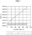
FIG. 1] FIG. 1 is a drawing illustrating the result of simulative evaluation of the main diffusing species in mayenite-type compounds having a C12A7 structure (Ca12Al14O33) containing Y as the metal M. - [
FIG. 2] FIG. 2 is a drawing exemplarily illustrating an example of a SOFC configuration containing an oxide ion-conducting solid electrolyte according to an embodiment of the present invention. - [
FIG. 3] FIG. 3 is a drawing exemplarily illustrating an example of a SOEC configuration containing an oxide ion-conducting solid electrolyte according to an embodiment of the present invention. - [
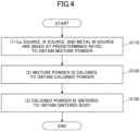
FIG. 4] FIG. 4 is a drawing exemplarily illustrating an example of a flow of a method for producing an oxide ion-conducting solid electrolyte according to an embodiment of the present invention. - [
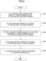
FIG. 5] FIG. 5 is a drawing exemplarily illustrating an example of a flow of another method for producing an oxide ion-conducting solid electrolyte according to an embodiment of the present invention. - [
FIG. 6] FIG. 6 is a drawing illustrating a Cole-Cole plot obtained from an oxide ion-conducting solid electrolyte (Sample 2) according to an embodiment of the present invention. - An embodiment of the present invention will be described below.
- According to an embodiment of the present invention, an oxide ion-conducting solid electrolyte is provided. The oxide ion-conducting solid electrolyte contains a mayenite-type compound having a representative composition represented by Ca12Al14O33, and at least one metal element M selected from lanthanum (La) and yttrium (Y), wherein the metal element M is contained in a range of from 0.4 mol% through 5.3 mol% in terms of an oxide relative to the whole of the oxide ion-conducting solid electrolyte.
- The oxide ion-conducting solid electrolyte according to an embodiment of the present invention (hereinafter, referred to as "first solid electrolyte") contains a mayenite-type compound having a C12A7 structure.
- Mayenite-type compounds have a representative composition represented by 12CaO·7Al2O3, and have a characteristic crystal structure containing voids (cages) that are three-dimensionally linked and each have a diameter of approximately 0.4 nm.
- The lattice framework that forms the cages bears positive charges, and forms twelve cages per unit cell. One sixth of the cages are internally occupied with oxide ions, and hence satisfy the crystal's electroneutrality condition. However, the oxide ions in such cages have a property chemically different from that of other oxygen ions that form the lattice framework. Hence, the oxide ions in the cages are referred to particularly as free oxide ions.
- Mayenite-type compounds are also represented by a composition formula: [Ca24Al28O64]4+(O2-)2 (NPL 2).
- Because mayenite-type compounds contain free oxide ions in the cages as described above, they may be able to function as oxide ion conductors (NPL 1).
- However, it has been confirmed by the present inventors' analyses that the ion-conducting property of typical mayenite-type compounds having the composition formula described above is not very high (for example, approximately 1/10 of YSZ).
- Hence, in order to apply mayenite-type compounds as oxide ion-conducting solid electrolytes, it is necessary to further improve their oxide ion-conducting property.
- So far, the present inventors have earnestly conducted research and development into the method for increasing the oxide ion-conducting property of mayenite-type compounds. As a result, the present inventors have found that addition of an oxide of a specific metal M to mayenite-type compounds can significantly increase the ion-conducting property of the mayenite-type compounds, and have achieved the present invention. Here, the metal M is either or both of lanthanum (La) and yttrium (Y).
- Hence, the first solid electrolyte contains either or both of La and Y.
- The metal M is contained in the oxide ion-conducting solid electrolyte in the range of from 0.4 mol% through 5.3 mol% in terms of an oxide.
- When the content of the metal M is less than 0.4 mol%, no significant effect may appear in the ion-conducting property of the mayenite-type compound. By adjusting the content of the metal M to 5.3 mol% or less, it is possible to obtain an oxide ion-conducting solid electrolyte scarcely containing a different phase and mainly composed of a mayenite-type compound in which the metal M is contained in the crystal structure.
- Particularly, in the first solid electrolyte, the mayenite-type compound itself may contain either or both of La and Y. In this case, either or both of La and Y may be positioned in the sites of Ca atoms of the mayenite-type compound. Particularly, the mole ratio (M/Ca) of the metal M to the Ca atom may be in the range of 0.015 ≤ M/Ca ≤ 0.19.
- In the first solid electrolyte, the metal M may satisfy 0.84 ≤ (M+Ca)/Al ≤ 0.88 on a mole ratio basis, and may satisfy Ca24-xMxAl28O66+x/2.
- Particularly, in the first solid electrolyte, it is preferable that the metal M is contained in the oxide ion-conducting solid electrolyte in the range of from 1.0 mol% through 5.1 mol% in terms of an oxide.
- Presently, the following is considered the reason why addition of a predetermined amount of the metal M to a mayenite-type compound in an embodiment of the present invention increases the ion-conducting property.
- When the metal M (either or both of La and Y) is added to a mayenite-type compound, it is considered that the metal M atoms are positioned to replace the sites of Ca atoms preferentially.
- Here, Ca atoms are divalent, whereas La atoms and Y atoms are trivalent. Hence, when Ca atoms are replaced with La atoms and Y atoms, the oxide ion concentration increases because of electroneutrality. Along with this, the concentration of the free oxide ions in the cages increases. As a result of this, it is considered that the ion-conducting property is improved. Moreover, the trivalent La has an ionic radius greater than that of the divalent Ca atom. Hence, when a site of a Ca atom is replaced with La, the distance between La and the oxide ion becomes greater, to weaken the electrostatic attractive force between La positioned in the site of the Ca atom and the oxide ion and facilitate migration of the free oxide ions in the cages. It is considered that the ion-conducting property is improved as a result.
- However, the described mechanism behind the improvement of the ion-conducting property is based on the experimental studies at present. The ion-conducting property of the first solid electrolyte may be improved through any other mechanism.
- The first solid electrolyte may further contain titanium (Ti).
- Ti may be contained in the range of from 0.1 mol% through 30 mol% in terms of TiO2 relative to the whole of the first solid electrolyte.
- In the first solid electrolyte, it is considered that Ti is positioned to replace the sites of aluminum (Al) atoms of the mayenite-type compound. The mole ratio Ti/Al of the Ti atom to the Al atom may be 0.015 ≤ Ti/Al ≤ 0.50. In a case where the first solid electrolyte contains Ti, the metal M may satisfy 0.84 ≤ (M+Ca)/(Al+Ti) ≤ 0.88 on a mole ratio basis, and may satisfy Ca24-xMxAl28-yTiyO66+x/2+y/2.
- When the first solid electrolyte contains Ti, the ion-conducting property is further improved. The reason is predicted as follows.
- When Ti is added to a mayenite-type compound, it is considered that Ti atoms are positioned to replace the sites of Al atoms preferentially. However, Al atoms are trivalent, whereas Ti atoms are tetravalent. Hence, when an Al atom is replaced with a Ti atom, the oxide ion concentration increases because of electroneutrality. Along with this, the concentration of the free oxide ions in the cages increases. As a result of this, it is considered that the ion-conducting property is improved.
- Such a first solid electrolyte has an ion-conducting property significantly higher than that of existing mayenite-type compounds. Hence, the first solid electrolyte is expected to be used as a solid electrolyte of, for example, a SOFC and a SOEC.
- The element that serves as the main ion conductor in the mayenite-type compound having a C12A7 structure containing the metal M was evaluated by simulation.
- In the simulation, a relationship between the mean square displacement MSD of the oxide ion in the material at 1 atm at 1200 K, and elapsed time was calculated based on the classical molecular dynamics calculation.
- The code used for the calculation was LAMMPS. For the two-body potential between the constituent elements of each material, which is an input parameter, values reported by Pedone et al. (
NPLs 3 and 4) were used. - An NPT-ensemble of a system, in which Y was substituted for 2.7 mol% of Ca in a 6×6×6 expanded supercell of a unit cell, was molecular-dynamically simulated for 1 nanosecond. After the temperature, the internal energy, and the lattice constants became stable, an NVE-ensemble was molecular-dynamically simulated for 1 nanosecond.
-
FIG. 1 illustrates the results of the simulation. InFIG. 1 , the horizontal axis represents elapsed time, and the vertical axis represents the MSD of each element. - The slope of the MSD is proportional to the coefficient of diffusion. Hence,
FIG. 1 indicates that an element having a greater MSD slope is more likely to be diffused inside a mayenite-type compound. - As indicated in
FIG. 1 , it was revealed that the main ion conductor in the compound obtained by substituting the metal M for some Ca atoms of a mayenite-type compound was the oxide ion. - Because of being ceramic, the first solid electrolyte has a high high-temperature stability. For example, the first solid electrolyte can be stably used in a temperature range of 800°C or higher.
- The first solid electrolyte is stable even at high temperatures, and has a significantly high oxide ion-conducting property. Hence, the first solid electrolyte can be used as a solid electrolyte layer of a Solid Oxide Fuel Cell (SOFC) and a solid electrolyte layer of a SOEC.
-
FIG. 2 exemplarily illustrates an example of the configuration of a SOFC. - As illustrated in
FIG. 2 , theSOFC 100 includes anoxygen electrode 110, afuel electrode 120, and asolid electrolyte layer 130 between these electrodes. - For example, the following reaction occurs at the oxygen electrode 110:
O2+4e-→2O2- Formula (1)
- The oxide ion produced at the
oxygen electrode 110 passes through thesolid electrolyte layer 130, and reaches thefuel electrode 120 on the opposite side. For example, the following reaction occurs at the fuel electrode 120:
2H2+2O2-→2H2O+4e- Formula (2)
- Hence, when the
SOFC 100 is connected to anexternal load 140, the reactions of Formula (1) and Formula (2) continue. Hence, power can be supplied to theexternal load 140. - In the
SOFC 100, for example, the first solid electrolyte can be used as thesolid electrolyte layer 130. The first solid electrolyte can also be used as the solid electrolyte component that forms theoxygen electrode 110 and thefuel electrode 120. - The
SOFC 100 can obtain a significantly high power generation efficiency, because thesolid electrolyte layer 130 has a significantly high oxide ion-conducting property. -
FIG. 3 exemplarily illustrates an example of the configuration of a SOEC. - As illustrated in
FIG. 3 , theSOEC 200 includes anoxygen electrode 210, ahydrogen electrode 220, and asolid electrolyte layer 230 between these electrodes. - For example, the following reaction occurs at the oxygen electrode 210:
2O2-→O2+4e- Formula (3)
- Moreover, for example, the following reaction occurs at the hydrogen electrode 220:
2H2O+4e-→2H2+2O2- Formula (4)
- The oxide ion produced at the
hydrogen electrode 220 passes through thesolid electrolyte layer 230 and reaches theoxygen electrode 210 on the opposite side. Hence, when theSOEC 200 is connected to anexternal power supply 240, the reactions of Formula (3) and Formula (4) continue. - In the
SOEC 200, for example, the first solid electrolyte can be used as thesolid electrolyte layer 230. The first solid electrolyte can also be used as the solid electrolyte component that forms theoxygen electrode 210 and thehydrogen electrode 220. - The
SOEC 200 can obtain a significantly high electrolysis efficiency, because thesolid electrolyte layer 230 has a significantly high oxide ion-conducting property. - Moreover, the solid electrolyte according to an embodiment of the present invention may be used in any form. For example, the solid electrolyte according to an embodiment of the present invention may be provided in the form of a powder. Alternatively, the solid electrolyte according to an embodiment of the present invention may be provided in the form of a slurry, a paste, or a dispersion liquid by being mixed with, for example, either or both of a solvent and a binder.
- In addition to these, various forms of use are conceivable.
- Next, with reference to
FIG. 4 , an example of a method for producing the oxide ion-conducting solid electrolyte according to an embodiment of the present invention will be described. -
FIG. 4 exemplarily illustrates an example of the flow of the method for producing the oxide ion-conducting solid electrolyte according to an embodiment of the present invention (hereinafter, referred to as "first production method"). - As illustrated in
FIG. 4 , the first production method includes: - (1) a step of mixing a Ca source, an Al source, and a metal M source at a predetermined ratio, to obtain a mixture powder (step S110);
- (2) a step of calcining the mixture powder, to obtain a calcined powder (step S120); and
- (3) a step of sintering the calcined powder, to obtain a sintered body (step S130).
- Each step will be described below.
- First, a mixture powder is prepared. For this purpose, a Ca source, an Al source, and a metal M source are mixed at a predetermined ratio.
- The Ca source may be selected from, for example, metal calcium, calcium carbonate, calcium oxide, calcium hydroxide, calcium nitrate, and calcium acetate.
- The Al source may be selected from, for example, metal aluminum, α alumina, γ alumina, aluminum hydroxide, aluminum nitrate, and aluminum sulfate.
- The metal M source may be selected from, for example, metal lanthanum, lanthanum oxide, metal yttrium, and yttrium oxide.
- The raw materials are weighed out and mixed such that a mayenite-type compound having the intended composition is obtained.
- The mixing method is not particularly limited so long as a uniform mixture powder is obtained.
- Next, the mixture powder is calcined.
- The calcining step is performed in order to desorb compounds such as carbonic acid and nitric acid contained in the mixture powder, and facilitate production of the intended mayenite-type compound in the next sintering step.
- The calcining conditions are not particularly limited. However, in order to obtain the intended mixture oxide, the calcining temperature is preferably 1,000°C or higher. However, when the calcining temperature is excessively high, the mixture powder is excessively crystallized. Hence, the calcining temperature is preferably 1,300°C or lower.
- The calcining time is, for example, approximately from 5 hours through 24 hours. However, the calcining time varies depending on the calcining temperature. The higher the calcining temperature, the more the calcining time can be shortened.
- As a result, a calcined powder is obtained.
- The calcined powder may be pulverized as needed. The average particle diameter through pulverization may be in a range of, for example, from 0.1 um through 100 um.
- Next, the calcined powder is sintered.
- The sintering step is performed in order to obtain a dense sintered body having the intended crystal phase.
- The calcined powder may be molded before the sintering step, and the sintering step may be performed using the obtained molded body.
- For example, the molding conditions are not particularly limited. Common molding methods such as a uniaxial molding method or an isostatic pressing method may be employed.
- The sintering method is not particularly limited. For example, the calcined powder or a molded body may be sintered by a pressure-less sintering method at normal pressure.
- Alternatively, the calcined powder may be sintered using a pressure sintering method such as hot press sintering or spark plasma sintering. In this case, molding and sintering may be performed at the same time.
- The sintering temperature is not particularly limited so long as an appropriate sintered body is obtained, yet is preferably in a range of from 1,200°C through 1,400°C. When the sintering temperature is excessively low, a dense sintered body may not be obtained. When the sintering temperature is excessively high, the processed body may melt.
- It is desirable to select an appropriate sintering time depending on the sintering temperature. In general, sintering is completed in a shorter time as the sintering temperature is higher.
- An appropriate sintering time, which may vary depending on the sintering temperature, is, for example, approximately from 5 hours through 48 hours in a case of a pressure-less sintering method, and is, for example, approximately from 5 minutes through 60 minutes in a case of a pressure sintering process by a spark plasma.
- When a pressure sintering process is performed using a container made of carbon, carbon may adhere to the surface of the sintered body. In such a case, it is possible to remove the adhering carbon by a thermal treatment at an atmospheric pressure at from 800°C through 1,000°C for approximately 5 hours.
- Through the steps described above, the oxide ion-conducting solid electrolyte according to an embodiment of the present invention can be produced.
- Next, with reference to
FIG. 5 , an example of another method for producing the oxide ion-conducting solid electrolyte according to an embodiment of the present invention will be described. -
FIG. 5 exemplarily illustrates an example of the flow of the another method for producing the oxide ion-conducting solid electrolyte according to an embodiment of the present invention (hereinafter, referred to as "second production method"). - As illustrated in
FIG. 5 , the second production method includes: - (1) a step of mixing a Ca source and an Al source at a predetermined ratio, to obtain a first mixture powder (step S210);
- (2) a step of calcining the first mixture powder, to obtain a first calcined powder(step S220);
- (3) a step of mixing the first calcined powder and a metal M source at a predetermined ratio, to obtain a second mixture powder (step S230);
- (4) a step of calcining the second mixture powder, to obtain a second calcined powder (step S240); and
- (5) a step of sintering the second calcined powder, to obtain a sintered body (step S250).
- Each step included in the second production method can be easily understood by a person ordinarily skilled in the art based on the descriptions about the step S110 to the step S130 of the first production method described above. Hence, descriptions about the details of each step will be omitted here.
- However, in the second production method, the oxide ion-conducting solid electrolyte is produced through two calcining steps (step S220 and step S240), unlike in the first production method.
- In this case, it is possible to produce an oxide ion-conducting solid electrolyte having a more uniform composition than when the mixture powder containing the Ca source, the Al source, and the metal M source is calcined all at once as in the first production method.
- That is, according to the first production method, there is a possibility that a heterogenous phase may be formed through reaction of Ca and the metal M that have a high reactivity with each other. As compared with this, in the second production method, it is possible to previously prepare a calcined powder, in which Ca and Al have reacted and bound with each other, in the first calcining step (step S220). Hence, in the second calcining step (step S240), it is possible to more reliably introduce the metal M into a desired site in the mayenite-type compound.
- The method for producing the oxide ion-conducting solid electrolyte according to an embodiment of the present invention has been described above, using the first production method and the second production method as examples. However, the foregoing description is a mere example, and the oxide ion-conducting solid electrolyte according to an embodiment of the present invention may be produced by any other method such as a hydrothermal method, a sol/gel method, and a liquid phase combustion method.
- Examples of the present invention will be described below.
- In the following description, Example 1 to Example 12 are Examples, and Example 21 and Example 22 are Comparative Examples.
- A sintered body was produced by the following method.
- A calcium carbonate powder (4.19 g), an α alumina powder (2.55 g), and an yttrium oxide powder (0.107 g) were each weighed out. They were added into a pot in which
zirconia balls 5 mm in diameter and 10 cc of isopropanol were added, and pulverized and mixed for 3 hours by a planetary ball mill method. Next, the mixture powder was dried at 100°C, to remove isopropanol. Then, the mixture powder was further sieved, to be separated from the zirconia balls. - The obtained mixture powder was added into an alumina crucible, and calcined in open air at 1,200°C for 5 hours. The obtained sample was pulverized in an agate mortar, to produce a calcined powder.
- The calcined powder (1 g) was added into hardmetal dies for a diameter of 1.5 cm and uniaxially molded by application of a pressure of 20 kN using a hydraulic press machine. Then, the resulting product was isostatically pressed at 196 MPa, to produce a pellet having a diameter of 1.5 cm. The pellet was thermally treated in open air at 1,200°C for 12 hours, to obtain a sintered body having a diameter of 1.3 cm and a thickness of 2 mm.
- The obtained sintered body is referred to as "
Sample 1". InSample 1, the Y content was 0.70 mol% in terms of Y2O3, and the Y/Ca mole ratio was 0.023. - Sintered bodies were produced by the same method as in Example 1. However, in Example 2 to Example 4, mixture powders were prepared by changing the raw material blending ratios in [Blending step] described above from Example 1. The other steps were the same as in Example 1.
- The obtained sintered bodies are referred to as "
Sample 2" to "Sample 4". - A calcium carbonate powder (4.22 g), an α alumina powder (2.54 g), and a lanthanum oxide powder (0.0928 g) were each weighed out. They were added into a pot in which
zirconia balls 5 mm in diameter and 10 cc of isopropanol were added, and pulverized and mixed for 3 hours by a planetary ball mill method. Next, the mixture powder was dried at 100°C, to remove isopropanol. Then, the mixture powder was further sieved, to be separated from the zirconia balls. - The obtained mixture powder was added into an alumina crucible, and calcined in open air at 1,300°C for 5 hours. The obtained sample was pulverized in an agate mortar, to produce a calcined powder.
- The calcined powder (1 g) was added into hardmetal dies for a diameter of 1.5 cm and uniaxially molded by application of a pressure of 20 kN using a hydraulic press machine. Then, the resulting product was isostatically pressed at 196 MPa, to produce a pellet having a diameter of 1.5 cm. The pellet was thermally treated in open air at 1,300°C for 12 hours, to obtain a sintered body having a diameter of 1.3 cm and a thickness of 2 mm.
- The obtained sintered body is referred to as "
Sample 5". InSample 5, the La content was 0.42 mol% in terms of La2O3, and the La/Ca mole ratio was 0.014. - Sintered bodies were produced by the same method as in Example 5. However, in Example 6 to Example 9, mixture powders were prepared by changing the raw material blending ratios in [Blending step] described above from Example 5. The other steps were the same as in Example 5.
- The obtained sintered bodies are referred to as "Sample 6" to "
Sample 9". - A calcium carbonate powder (3.69 g), an α alumina powder (2.42 g), yttrium oxide (0.210 g), and a lanthanum oxide powder (0.303 g) were each weighed out. They were added into a pot in which
zirconia balls 5 mm in diameter and 10 cc of isopropanol were added, and pulverized and mixed for 3 hours by a planetary ball mill method. Next, the mixture powder was dried at 100°C, to remove isopropanol. Then, the mixture powder was further sieved, to be separated from the zirconia balls. - The obtained mixture powder was added into an alumina crucible, and calcined in open air at 1,300°C for 5 hours. The obtained sample was pulverized in an agate mortar, to produce a calcined powder.
- The calcined powder (1 g) was added into hardmetal dies for a diameter of 1.5 cm and uniaxially molded by application of a pressure of 20 kN using a hydraulic press machine. Then, the resulting product was isostatically pressed at 196 MPa, to produce a pellet having a diameter of 1.5 cm. The pellet was thermally treated in open air at 1,300°C for 12 hours, to obtain a sintered body having a diameter of 1.3 cm and a thickness of 2 mm.
- The obtained sintered body is referred to as "Sample 10". In Sample 10, the Y content was 1.5 mol% in terms of Y2O3, the La content was 1.5 mol% in terms of La2O3, and (Y+La)/Ca was 0.1 on the basis of a mole ratio M.
- A sintered body was produced by the same method as in Example 1. However, in Example 11, a titanium dioxide powder was used as a raw material in addition to a calcium carbonate powder, an α alumina powder, and an yttrium oxide powder in [Blending step] described above. The titanium dioxide powder was added in an amount of 11 mol% relative to the whole. The Ti/Al ratio in the mixture powder was 0.18.
- The other steps were the same as in Example 1.
- The obtained sintered body is referred to as "Sample 11". In
Sample 1, the Y content was 2.4 mol% in terms of Y2O3, and the Y/Ca mole ratio was 0.086. - A sintered body was produced by the same method as in Example 5. However, in Example 12, a titanium dioxide powder was used as a raw material in addition to a calcium carbonate powder, an α alumina powder, and a lanthanum oxide powder in [Blending step] described above. The titanium dioxide powder was added in an amount of 3.2 mol% relative to the whole. The Ti/Al ratio in the mixture powder was 0.045.
- The other steps were the same as in Example 5.
- The obtained sintered body was referred to as "Sample 12". In Sample 12, the La content was 2.9 mol% in terms of La2O3, and the La/Ca mole ratio was 0.1.
- A sintered body was produced by the same method as in Example 1. However, in Example 21, only calcium carbonate (4.33 g) and α alumina (2.57 g) were mixed in [Blending step] described above, to prepare a mixture powder. That is, a mixture powder was prepared without adding the metal M source. The other steps were the same as in Example 1.
- The obtained sintered body is referred to as "Sample 21".
- A sintered body was produced by the same method as in Example 1. However, in Example 22, a mixture powder was prepared by changing the raw material blending ratio in [Blending step] described above from Example 1. The Y content was 7.0 mol% in terms of Y2O3, and the Y/Ca mole ratio was 0.26.
- The firing temperature in [Sintering step] described above was 1,150°C.
- The other steps were the same as in Example 1.
- The obtained sintered body is referred to as "Sample 22".
- For example, the raw materials of each sample and the firing condition are collectively indicated in Table 1 below.
[Table 1] Sample No. Metal M Ti content (mol%) in terms of oxide Ti/Al (mole ratio) Firing temperature (°C) Type Content (mol%) in terms of oxide M/Ca (mole ratio) 1 Y 0.70 0.023 - - 1,200 2 Y 1.6 0.053 - - 1,200 3 Y 2.8 0.096 - - 1,200 4 Y 5.1 0.18 - - 1,200 5 La 0.42 0.014 - - 1,300 6 La 0.70 0.023 - - 1,300 7 La 1.60 0.053 - - 1, 300 8 La 2.8 0.096 - - 1, 300 9 La 5.1 0.18 - - 1,300 10 Y+La 1.5+1.5 0.1 - - 1,300 11 Y 2.4 0.086 11 0.18 1,200 12 La 2.9 0.1 3.2 0.045 1,300 21 Absent - 0 - - 1,200 22 Y 7.0 0.26 - - 1,150 - Each sample was evaluated in terms of the following.
- Resistivity measurement was performed using each sample. For resistivity measurement, an impedance method was used.
- First, the surface of each sample was polished with sandpaper of from #80 through #1000 to remove some of the surface and smooth it out.
- Next, a platinum electrode having a diameter of 6 mm and a thickness of 10 um was set on the polished surface via a platinum paste. This sample was thermally treated in an open air atmosphere at 1,000°C for 15 minutes, to solidify the platinum paste.
- Next, the sample was set in an electric furnace having an open air atmosphere. The sample was connected to a potentio-galvanostat (SP-150 obtained from Biologic, Inc.) through a platinum wire coupled to the platinum electrode.
- Next, the sample was heated to 850°C, and retained in the state for 120 minutes, to stabilize the temperature of the sample.
- After the temperature of the sample stabilized, impedance measurement was performed, to generate a Cole-Cole plot. The measurement frequency was from 1 MHz through 100 mHz.
- The resistivity was obtained at the intersection with the horizontal axis (real axis) of the obtained Cole-Cole plot.
-
FIG. 6 illustrates the Cole-Cole plot obtained fromSample 2, as an example. In this example, the resistivity ofSample 2 was obtained based on the position of the arrow. - Table 2 below indicates the results of measurements of the samples collectively. In Table 2, the resistivity of each sample is indicated as a ratio to the resistivity obtained from Sample 21.
[Table 2] Sample No. Resistivity (relative ratio) 1 0.41 2 0.36 3 0.24 4 0.35 5 0.43 6 0.36 7 0.22 8 0.093 9 0.21 10 0.2 11 0.09 12 0.078 21 1 22 0.89 - From these results, it can be seen that Sample 22 had a resistivity of 0.89, which was not much of a decrease from that of Sample 21, which is a mayenite-type compound free of the metal M.
- On the other hand, it was revealed that the resistivities of
Sample 1 to Sample 12 were greatly decreased from that of Sample 21. Particularly, it was revealed the resistivities of Sample 11 and Sample 12 containing titanium oxide were greatly decreased. - Hence, it was revealed that the resistivity significantly decreased in the mayenite-type compound samples to which the metal M was added in an amount of from 0.4 mol% through 5.3 mol% in terms of an oxide.
- From these results, it could be inferred that a solid electrolyte obtained by adding the metal M to a mayenite-type compound could exhibit a better ion-conducting property than could by existing mayenite-type compounds.
- The present invention includes the following aspects.
- An oxide ion-conducting solid electrolyte, including:
- a mayenite-type compound having a representative composition represented by Ca12Al14O33; and
- at least one metal element M selected from lanthanum (La) and yttrium (Y),
- wherein the metal element M is contained in a range of from 0.4 mol% through 5.3 mol% in terms of an oxide relative to a whole of the oxide ion-conducting solid electrolyte.
- The oxide ion-conducting solid electrolyte according to
Aspect 1,
wherein the metal element M is contained in the mayenite-type compound. - The oxide ion-conducting solid electrolyte according to
Aspect 2,
wherein the metal element M is positioned in a site of a Ca atom in the mayenite-type compound. - The oxide ion-conducting solid electrolyte according to any one of
Aspects 1 to 3,
wherein a mole ratio (M/Ca) of the metal element M to Ca atom satisfies 0.015 ≤ M/Ca ≤ 0.19. - The oxide ion-conducting solid electrolyte according to any one of
Aspects 1 to 4, further including:
titanium (Ti) in an amount of from 0.1 mol% through 30 mol% in terms of TiO2. - The oxide ion-conducting solid electrolyte according to
Aspect 5,
wherein the Ti is positioned in a site of an Al atom in the mayenite-type compound. - The oxide ion-conducting solid electrolyte according to any one of
Aspects 1 to 6,
wherein 0.84 ≤ (M+Ca)/Al ≤ 0.88 is satisfied. - A fuel battery cell, including:
the oxide ion-conducting solid electrolyte of any one ofAspects 1 to 7. - An electrolysis cell, including:
the oxide ion-conducting solid electrolyte of any one ofAspects 1 to 7. - The present application claims priority to
Japanese Patent Application No. 2021-142548 filed September 1, 2021 -
- 100
- SOFC
- 110
- oxygen electrode
- 120
- fuel electrode
- 130
- solid electrolyte layer
- 140
- external load
- 200
- SOEC
- 210
- oxygen electrode
- 220
- hydrogen electrode
- 230
- solid electrolyte layer
- 240
- external power supply
Claims (9)
- An oxide ion-conducting solid electrolyte, comprising:a mayenite-type compound having a representative composition represented by Ca12Al14O33; andat least one metal element M selected from lanthanum (La) and yttrium (Y),wherein the metal element M is contained in a range of from 0.4 mol% through 5.3 mol% in terms of an oxide relative to a whole of the oxide ion-conducting solid electrolyte.
- The oxide ion-conducting solid electrolyte according to claim 1,
wherein the metal element M is contained in the mayenite-type compound. - The oxide ion-conducting solid electrolyte according to claim 2,
wherein the metal element M is positioned in a site of a Ca atom in the mayenite-type compound. - The oxide ion-conducting solid electrolyte according to claim 1 or 2,
wherein a mole ratio (M/Ca) of the metal element M to Ca atom satisfies 0.015 ≤ M/Ca ≤ 0.19. - The oxide ion-conducting solid electrolyte according to claim 1 or 2, further comprising:
titanium (Ti) in an amount of from 0.1 mol% through 30 mol% in terms of TiO2. - The oxide ion-conducting solid electrolyte according to claim 5,
wherein the Ti is positioned in a site of an Al atom in the mayenite-type compound. - The oxide ion-conducting solid electrolyte according to claim 1 or 2,
wherein 0.84 ≤ (M+Ca)/Al ≤ 0.88 is satisfied. - A fuel battery cell, comprising:
the oxide ion-conducting solid electrolyte of claim 1 or 2. - An electrolysis cell, comprising:
the oxide ion-conducting solid electrolyte of claim 1 or 2.
Applications Claiming Priority (2)
| Application Number | Priority Date | Filing Date | Title |
|---|---|---|---|
| JP2021142548 | 2021-09-01 | ||
| PCT/JP2022/029929 WO2023032584A1 (en) | 2021-09-01 | 2022-08-04 | Oxide ion-conducting solid electrolyte |
Publications (2)
| Publication Number | Publication Date |
|---|---|
| EP4398268A1 true EP4398268A1 (en) | 2024-07-10 |
| EP4398268A4 EP4398268A4 (en) | 2025-11-05 |
Family
ID=85410982
Family Applications (1)
| Application Number | Title | Priority Date | Filing Date |
|---|---|---|---|
| EP22864170.0A Pending EP4398268A4 (en) | 2021-09-01 | 2022-08-04 | Oxide-conducting solid electrolyte |
Country Status (4)
| Country | Link |
|---|---|
| US (1) | US20240194919A1 (en) |
| EP (1) | EP4398268A4 (en) |
| JP (1) | JPWO2023032584A1 (en) |
| WO (1) | WO2023032584A1 (en) |
Family Cites Families (8)
| Publication number | Priority date | Publication date | Assignee | Title |
|---|---|---|---|---|
| JP3560580B2 (en) * | 2001-10-18 | 2004-09-02 | 独立行政法人 科学技術振興機構 | 12CaO · 7Al2O3 compound and method for producing the same |
| JP2007031248A (en) * | 2005-07-29 | 2007-02-08 | Oxy Japan:Kk | Substance that includes negatively charged oxygen atoms and method for producing the same |
| JP4931175B2 (en) * | 2005-09-14 | 2012-05-16 | 株式会社アルバック | Phosphor for electron beam excited light emitting device, method for producing the same, and electron beam excited light emitting device |
| JP2014112474A (en) * | 2012-12-05 | 2014-06-19 | Toyota Central R&D Labs Inc | Solid electrolyte |
| JP6062192B2 (en) * | 2012-09-11 | 2017-01-18 | 国立大学法人東京工業大学 | Mayenite composite and cathode for electron emission |
| KR101323098B1 (en) * | 2013-04-12 | 2013-10-30 | 한국세라믹기술원 | Manufacturing method of mayenite electride with improved electric conductivity |
| WO2019189701A1 (en) * | 2018-03-29 | 2019-10-03 | 国立大学法人東京工業大学 | Electrolytic cell and electrolytic device |
| JP2021142548A (en) | 2020-03-12 | 2021-09-24 | 久雄 石川 | Solder, method for producing solder and soldering component |
-
2022
- 2022-08-04 WO PCT/JP2022/029929 patent/WO2023032584A1/en not_active Ceased
- 2022-08-04 JP JP2023545182A patent/JPWO2023032584A1/ja active Pending
- 2022-08-04 EP EP22864170.0A patent/EP4398268A4/en active Pending
-
2024
- 2024-02-19 US US18/444,839 patent/US20240194919A1/en active Pending
Also Published As
| Publication number | Publication date |
|---|---|
| JPWO2023032584A1 (en) | 2023-03-09 |
| US20240194919A1 (en) | 2024-06-13 |
| EP4398268A4 (en) | 2025-11-05 |
| WO2023032584A1 (en) | 2023-03-09 |
Similar Documents
| Publication | Publication Date | Title |
|---|---|---|
| Talebi et al. | Investigation on microstructures of NiO–YSZ composite and Ni–YSZ cermet for SOFCs | |
| Hong et al. | Barium carbonate nanoparticle as high temperature oxygen reduction catalyst for solid oxide fuel cell | |
| Liu et al. | Preparation and characterization of graded cathode La0. 6Sr0. 4Co0. 2Fe0. 8O3− δ | |
| KR101808387B1 (en) | Ceria electrolyte for low temperature sintering and solid oxide fuel cells using the same | |
| JP2018190730A (en) | Proton-conducting oxide fuel cell manufacturing method | |
| Liu et al. | Fabrication and characterization of a co-fired La0. 6Sr0. 4Co0. 2Fe0. 8O3− δ cathode-supported Ce0. 9Gd0. 1O1. 95 thin-film for IT-SOFCs | |
| Fan et al. | Barium cerate-zirconate electrolyte powder prepared by carbonate coprecipitation for high performance protonic ceramic fuel cells | |
| Sarıboğa et al. | Cellulose templating method for the preparation of La0. 8Sr0. 2Ga0. 83Mg0. 17O2. 815 (LSGM) solid oxide electrolyte | |
| Ding et al. | Processing and characterization of novel Ce0. 8Sm0. 1Bi0. 1O2-δ-BaCe0. 8Sm0. 1Bi0. 1O3-δ (BiSDC-BCSBi) composite electrolytes for intermediate-temperature solid oxide fuel cells | |
| Li et al. | Sinterability and electrical properties of ZnO-doped Ce0. 8Y0. 2O1. 9 electrolytes prepared by an EDTA–citrate complexing method | |
| AU2008210043B2 (en) | A composite material suitable for use as an electrode material in a SOC | |
| Kuğuoğlu et al. | Preparation and characterization of La0. 8Sr0. 2Ga0. 83Mg0. 17O3 electrolyte by polyol method for solid oxide fuel cells | |
| Ghosh et al. | La0. 54Sr0. 4Fe0. 2Co0. 8O3− δ@ Co0. 01Ce0. 79Gd0. 2O2− δ functional cathode material for solid oxide fuel cell application | |
| Bucevac et al. | Effect of preparation route on the microstructure and electrical conductivity of co-doped ceria | |
| US12451505B2 (en) | Oxide ion-conducting solid electrolyte | |
| JP7711506B2 (en) | Oxide-ion conducting solid electrolyte | |
| EP4398269A1 (en) | Oxide ion conductive solid electrolyte | |
| US20240194919A1 (en) | Oxide ion-conducting solid electrolyte | |
| JP2000044340A (en) | Lanthanum gallate-based sintered body, method for producing the same, and fuel cell using the same as solid electrolyte | |
| EP4431459A1 (en) | Oxide ion-conducting solid electrolyte | |
| Marinšek et al. | Microstructure evaluation of sintered combustion-derived fine powder NiO–YSZ | |
| Chen et al. | The structures, morphologies and intermediate-temperature electrochemical properties of CuO aided sintering Gd3+ and Ho3+ co-doped ceria electrolytes | |
| JP2025089100A (en) | Electrolyte particles for use in the manufacture of solid oxide electrochemical cells and their manufacturing method, electrolyte-forming dispersion, and electrolyte sintered body and its manufacturing method | |
| EP4431482A1 (en) | Oxide ion-conducting solid electrolyte | |
| Nesaraj et al. | Synthesis and characterization of LaCoO 3 based cathode and its chemical compatibility with CeO 2 based electrolytes for intermediate temperature solid oxide fuel cell(ITSOFC) |
Legal Events
| Date | Code | Title | Description |
|---|---|---|---|
| STAA | Information on the status of an ep patent application or granted ep patent |
Free format text: STATUS: THE INTERNATIONAL PUBLICATION HAS BEEN MADE |
|
| PUAI | Public reference made under article 153(3) epc to a published international application that has entered the european phase |
Free format text: ORIGINAL CODE: 0009012 |
|
| STAA | Information on the status of an ep patent application or granted ep patent |
Free format text: STATUS: REQUEST FOR EXAMINATION WAS MADE |
|
| 17P | Request for examination filed |
Effective date: 20240223 |
|
| AK | Designated contracting states |
Kind code of ref document: A1 Designated state(s): AL AT BE BG CH CY CZ DE DK EE ES FI FR GB GR HR HU IE IS IT LI LT LU LV MC MK MT NL NO PL PT RO RS SE SI SK SM TR |
|
| DAV | Request for validation of the european patent (deleted) | ||
| DAX | Request for extension of the european patent (deleted) | ||
| A4 | Supplementary search report drawn up and despatched |
Effective date: 20251002 |
|
| RIC1 | Information provided on ipc code assigned before grant |
Ipc: H01B 1/08 20060101AFI20250926BHEP Ipc: C04B 35/44 20060101ALI20250926BHEP Ipc: H01M 8/12 20160101ALI20250926BHEP Ipc: H01M 8/1246 20160101ALI20250926BHEP Ipc: C01F 17/32 20200101ALI20250926BHEP Ipc: C25B 13/04 20210101ALI20250926BHEP Ipc: C25B 13/07 20210101ALI20250926BHEP Ipc: C25B 9/23 20210101ALI20250926BHEP Ipc: C01F 7/164 20220101ALI20250926BHEP |