WO2023032584A1 - Oxide ion-conducting solid electrolyte - Google Patents
Oxide ion-conducting solid electrolyte Download PDFInfo
- Publication number
- WO2023032584A1 WO2023032584A1 PCT/JP2022/029929 JP2022029929W WO2023032584A1 WO 2023032584 A1 WO2023032584 A1 WO 2023032584A1 JP 2022029929 W JP2022029929 W JP 2022029929W WO 2023032584 A1 WO2023032584 A1 WO 2023032584A1
- Authority
- WO
- WIPO (PCT)
- Prior art keywords
- solid electrolyte
- oxide ion
- ion conductive
- oxide
- conductive solid
- Prior art date
Links
- 239000007784 solid electrolyte Substances 0.000 title claims abstract description 101
- 150000001875 compounds Chemical class 0.000 claims abstract description 48
- 229910052751 metal Inorganic materials 0.000 claims abstract description 45
- 239000002184 metal Substances 0.000 claims abstract description 45
- 239000000203 mixture Substances 0.000 claims abstract description 10
- 229910052727 yttrium Inorganic materials 0.000 claims abstract description 9
- VWQVUPCCIRVNHF-UHFFFAOYSA-N yttrium atom Chemical compound [Y] VWQVUPCCIRVNHF-UHFFFAOYSA-N 0.000 claims abstract description 6
- AHKZTVQIVOEVFO-UHFFFAOYSA-N oxide(2-) Chemical compound [O-2] AHKZTVQIVOEVFO-UHFFFAOYSA-N 0.000 claims description 61
- 239000010936 titanium Substances 0.000 claims description 23
- 239000000446 fuel Substances 0.000 claims description 9
- 229910052791 calcium Inorganic materials 0.000 claims description 8
- 229910052746 lanthanum Inorganic materials 0.000 claims description 7
- FZLIPJUXYLNCLC-UHFFFAOYSA-N lanthanum atom Chemical compound [La] FZLIPJUXYLNCLC-UHFFFAOYSA-N 0.000 claims description 6
- 229910052782 aluminium Inorganic materials 0.000 claims description 5
- 229910010413 TiO 2 Inorganic materials 0.000 claims description 3
- RTAQQCXQSZGOHL-UHFFFAOYSA-N Titanium Chemical compound [Ti] RTAQQCXQSZGOHL-UHFFFAOYSA-N 0.000 claims description 3
- 229910052719 titanium Inorganic materials 0.000 claims description 3
- 239000011575 calcium Substances 0.000 description 40
- 239000000843 powder Substances 0.000 description 39
- 239000011812 mixed powder Substances 0.000 description 28
- 238000005245 sintering Methods 0.000 description 27
- 125000004429 atom Chemical group 0.000 description 25
- 238000004519 manufacturing process Methods 0.000 description 22
- 238000000034 method Methods 0.000 description 21
- 150000002500 ions Chemical class 0.000 description 20
- 238000001354 calcination Methods 0.000 description 19
- VTYYLEPIZMXCLO-UHFFFAOYSA-L Calcium carbonate Chemical compound [Ca+2].[O-]C([O-])=O VTYYLEPIZMXCLO-UHFFFAOYSA-L 0.000 description 14
- 239000001301 oxygen Substances 0.000 description 13
- 229910052760 oxygen Inorganic materials 0.000 description 13
- KFZMGEQAYNKOFK-UHFFFAOYSA-N Isopropanol Chemical compound CC(C)O KFZMGEQAYNKOFK-UHFFFAOYSA-N 0.000 description 12
- MCMNRKCIXSYSNV-UHFFFAOYSA-N Zirconium dioxide Chemical compound O=[Zr]=O MCMNRKCIXSYSNV-UHFFFAOYSA-N 0.000 description 12
- QVGXLLKOCUKJST-UHFFFAOYSA-N atomic oxygen Chemical compound [O] QVGXLLKOCUKJST-UHFFFAOYSA-N 0.000 description 12
- 239000010410 layer Substances 0.000 description 12
- PNEYBMLMFCGWSK-UHFFFAOYSA-N Alumina Chemical compound [O-2].[O-2].[O-2].[Al+3].[Al+3] PNEYBMLMFCGWSK-UHFFFAOYSA-N 0.000 description 11
- GWEVSGVZZGPLCZ-UHFFFAOYSA-N Titan oxide Chemical compound O=[Ti]=O GWEVSGVZZGPLCZ-UHFFFAOYSA-N 0.000 description 9
- BASFCYQUMIYNBI-UHFFFAOYSA-N platinum Chemical compound [Pt] BASFCYQUMIYNBI-UHFFFAOYSA-N 0.000 description 9
- MRELNEQAGSRDBK-UHFFFAOYSA-N lanthanum(3+);oxygen(2-) Chemical compound [O-2].[O-2].[O-2].[La+3].[La+3] MRELNEQAGSRDBK-UHFFFAOYSA-N 0.000 description 8
- 238000000465 moulding Methods 0.000 description 8
- 229910000019 calcium carbonate Inorganic materials 0.000 description 7
- 239000001257 hydrogen Substances 0.000 description 7
- 229910052739 hydrogen Inorganic materials 0.000 description 7
- 239000002994 raw material Substances 0.000 description 7
- UFHFLCQGNIYNRP-UHFFFAOYSA-N Hydrogen Chemical compound [H][H] UFHFLCQGNIYNRP-UHFFFAOYSA-N 0.000 description 6
- 238000006243 chemical reaction Methods 0.000 description 6
- 238000002156 mixing Methods 0.000 description 6
- 239000008188 pellet Substances 0.000 description 6
- 238000002360 preparation method Methods 0.000 description 6
- 239000013078 crystal Substances 0.000 description 5
- 238000005259 measurement Methods 0.000 description 5
- 238000010586 diagram Methods 0.000 description 4
- 230000002706 hydrostatic effect Effects 0.000 description 4
- SIWVEOZUMHYXCS-UHFFFAOYSA-N oxo(oxoyttriooxy)yttrium Chemical compound O=[Y]O[Y]=O SIWVEOZUMHYXCS-UHFFFAOYSA-N 0.000 description 4
- 229910052697 platinum Inorganic materials 0.000 description 4
- 238000004088 simulation Methods 0.000 description 4
- 239000004408 titanium dioxide Substances 0.000 description 4
- 229910001233 yttria-stabilized zirconia Inorganic materials 0.000 description 4
- OKTJSMMVPCPJKN-UHFFFAOYSA-N Carbon Chemical compound [C] OKTJSMMVPCPJKN-UHFFFAOYSA-N 0.000 description 3
- CURLTUGMZLYLDI-UHFFFAOYSA-N Carbon dioxide Chemical compound O=C=O CURLTUGMZLYLDI-UHFFFAOYSA-N 0.000 description 3
- 229910021193 La 2 O 3 Inorganic materials 0.000 description 3
- VYPSYNLAJGMNEJ-UHFFFAOYSA-N Silicium dioxide Chemical compound O=[Si]=O VYPSYNLAJGMNEJ-UHFFFAOYSA-N 0.000 description 3
- 238000000498 ball milling Methods 0.000 description 3
- 229910052799 carbon Inorganic materials 0.000 description 3
- 238000013329 compounding Methods 0.000 description 3
- 238000011156 evaluation Methods 0.000 description 3
- 239000000463 material Substances 0.000 description 3
- 238000000329 molecular dynamics simulation Methods 0.000 description 3
- 239000004570 mortar (masonry) Substances 0.000 description 3
- 239000006072 paste Substances 0.000 description 3
- 239000012071 phase Substances 0.000 description 3
- 238000003825 pressing Methods 0.000 description 3
- 239000007787 solid Substances 0.000 description 3
- UGFAIRIUMAVXCW-UHFFFAOYSA-N Carbon monoxide Chemical compound [O+]#[C-] UGFAIRIUMAVXCW-UHFFFAOYSA-N 0.000 description 2
- XAGFODPZIPBFFR-UHFFFAOYSA-N aluminium Chemical compound [Al] XAGFODPZIPBFFR-UHFFFAOYSA-N 0.000 description 2
- ZCCIPPOKBCJFDN-UHFFFAOYSA-N calcium nitrate Chemical compound [Ca+2].[O-][N+]([O-])=O.[O-][N+]([O-])=O ZCCIPPOKBCJFDN-UHFFFAOYSA-N 0.000 description 2
- 238000004364 calculation method Methods 0.000 description 2
- 229910002091 carbon monoxide Inorganic materials 0.000 description 2
- 238000009792 diffusion process Methods 0.000 description 2
- 238000005868 electrolysis reaction Methods 0.000 description 2
- VNWKTOKETHGBQD-UHFFFAOYSA-N methane Chemical compound C VNWKTOKETHGBQD-UHFFFAOYSA-N 0.000 description 2
- -1 oxygen ions Chemical class 0.000 description 2
- 238000001272 pressureless sintering Methods 0.000 description 2
- BNGXYYYYKUGPPF-UHFFFAOYSA-M (3-methylphenyl)methyl-triphenylphosphanium;chloride Chemical compound [Cl-].CC1=CC=CC(C[P+](C=2C=CC=CC=2)(C=2C=CC=CC=2)C=2C=CC=CC=2)=C1 BNGXYYYYKUGPPF-UHFFFAOYSA-M 0.000 description 1
- OYPRJOBELJOOCE-UHFFFAOYSA-N Calcium Chemical compound [Ca] OYPRJOBELJOOCE-UHFFFAOYSA-N 0.000 description 1
- GRYLNZFGIOXLOG-UHFFFAOYSA-N Nitric acid Chemical compound O[N+]([O-])=O GRYLNZFGIOXLOG-UHFFFAOYSA-N 0.000 description 1
- WNROFYMDJYEPJX-UHFFFAOYSA-K aluminium hydroxide Chemical compound [OH-].[OH-].[OH-].[Al+3] WNROFYMDJYEPJX-UHFFFAOYSA-K 0.000 description 1
- DIZPMCHEQGEION-UHFFFAOYSA-H aluminium sulfate (anhydrous) Chemical compound [Al+3].[Al+3].[O-]S([O-])(=O)=O.[O-]S([O-])(=O)=O.[O-]S([O-])(=O)=O DIZPMCHEQGEION-UHFFFAOYSA-H 0.000 description 1
- 238000004458 analytical method Methods 0.000 description 1
- 239000011230 binding agent Substances 0.000 description 1
- 230000015572 biosynthetic process Effects 0.000 description 1
- VSGNNIFQASZAOI-UHFFFAOYSA-L calcium acetate Chemical compound [Ca+2].CC([O-])=O.CC([O-])=O VSGNNIFQASZAOI-UHFFFAOYSA-L 0.000 description 1
- 239000001639 calcium acetate Substances 0.000 description 1
- 229960005147 calcium acetate Drugs 0.000 description 1
- 235000011092 calcium acetate Nutrition 0.000 description 1
- AXCZMVOFGPJBDE-UHFFFAOYSA-L calcium dihydroxide Chemical compound [OH-].[OH-].[Ca+2] AXCZMVOFGPJBDE-UHFFFAOYSA-L 0.000 description 1
- 239000000920 calcium hydroxide Substances 0.000 description 1
- 229910001861 calcium hydroxide Inorganic materials 0.000 description 1
- BRPQOXSCLDDYGP-UHFFFAOYSA-N calcium oxide Chemical compound [O-2].[Ca+2] BRPQOXSCLDDYGP-UHFFFAOYSA-N 0.000 description 1
- 239000000292 calcium oxide Substances 0.000 description 1
- ODINCKMPIJJUCX-UHFFFAOYSA-N calcium oxide Inorganic materials [Ca]=O ODINCKMPIJJUCX-UHFFFAOYSA-N 0.000 description 1
- 239000001569 carbon dioxide Substances 0.000 description 1
- 229910002092 carbon dioxide Inorganic materials 0.000 description 1
- 239000004568 cement Substances 0.000 description 1
- 239000000919 ceramic Substances 0.000 description 1
- 238000009841 combustion method Methods 0.000 description 1
- 230000000052 comparative effect Effects 0.000 description 1
- 239000000470 constituent Substances 0.000 description 1
- 238000002425 crystallisation Methods 0.000 description 1
- 230000008025 crystallization Effects 0.000 description 1
- 239000006185 dispersion Substances 0.000 description 1
- 238000006073 displacement reaction Methods 0.000 description 1
- 230000000694 effects Effects 0.000 description 1
- 238000010304 firing Methods 0.000 description 1
- 239000007789 gas Substances 0.000 description 1
- 238000010438 heat treatment Methods 0.000 description 1
- 150000002431 hydrogen Chemical class 0.000 description 1
- 238000001027 hydrothermal synthesis Methods 0.000 description 1
- 239000010416 ion conductor Substances 0.000 description 1
- 239000007791 liquid phase Substances 0.000 description 1
- 229910017604 nitric acid Inorganic materials 0.000 description 1
- 239000002245 particle Substances 0.000 description 1
- 238000010248 power generation Methods 0.000 description 1
- 238000010298 pulverizing process Methods 0.000 description 1
- 238000012827 research and development Methods 0.000 description 1
- 239000002002 slurry Substances 0.000 description 1
- 238000003980 solgel method Methods 0.000 description 1
- 239000002904 solvent Substances 0.000 description 1
- 229910002076 stabilized zirconia Inorganic materials 0.000 description 1
- 239000000126 substance Substances 0.000 description 1
- 239000002344 surface layer Substances 0.000 description 1
- OGIDPMRJRNCKJF-UHFFFAOYSA-N titanium oxide Inorganic materials [Ti]=O OGIDPMRJRNCKJF-UHFFFAOYSA-N 0.000 description 1
- XLYOFNOQVPJJNP-UHFFFAOYSA-N water Substances O XLYOFNOQVPJJNP-UHFFFAOYSA-N 0.000 description 1
Images


Classifications
-
- C—CHEMISTRY; METALLURGY
- C01—INORGANIC CHEMISTRY
- C01F—COMPOUNDS OF THE METALS BERYLLIUM, MAGNESIUM, ALUMINIUM, CALCIUM, STRONTIUM, BARIUM, RADIUM, THORIUM, OR OF THE RARE-EARTH METALS
- C01F17/00—Compounds of rare earth metals
- C01F17/30—Compounds containing rare earth metals and at least one element other than a rare earth metal, oxygen or hydrogen, e.g. La4S3Br6
- C01F17/32—Compounds containing rare earth metals and at least one element other than a rare earth metal, oxygen or hydrogen, e.g. La4S3Br6 oxide or hydroxide being the only anion, e.g. NaCeO2 or MgxCayEuO
-
- C—CHEMISTRY; METALLURGY
- C01—INORGANIC CHEMISTRY
- C01F—COMPOUNDS OF THE METALS BERYLLIUM, MAGNESIUM, ALUMINIUM, CALCIUM, STRONTIUM, BARIUM, RADIUM, THORIUM, OR OF THE RARE-EARTH METALS
- C01F7/00—Compounds of aluminium
- C01F7/02—Aluminium oxide; Aluminium hydroxide; Aluminates
- C01F7/16—Preparation of alkaline-earth metal aluminates or magnesium aluminates; Aluminium oxide or hydroxide therefrom
- C01F7/164—Calcium aluminates
-
- C—CHEMISTRY; METALLURGY
- C04—CEMENTS; CONCRETE; ARTIFICIAL STONE; CERAMICS; REFRACTORIES
- C04B—LIME, MAGNESIA; SLAG; CEMENTS; COMPOSITIONS THEREOF, e.g. MORTARS, CONCRETE OR LIKE BUILDING MATERIALS; ARTIFICIAL STONE; CERAMICS; REFRACTORIES; TREATMENT OF NATURAL STONE
- C04B35/00—Shaped ceramic products characterised by their composition; Ceramics compositions; Processing powders of inorganic compounds preparatory to the manufacturing of ceramic products
- C04B35/01—Shaped ceramic products characterised by their composition; Ceramics compositions; Processing powders of inorganic compounds preparatory to the manufacturing of ceramic products based on oxide ceramics
- C04B35/44—Shaped ceramic products characterised by their composition; Ceramics compositions; Processing powders of inorganic compounds preparatory to the manufacturing of ceramic products based on oxide ceramics based on aluminates
-
- C—CHEMISTRY; METALLURGY
- C25—ELECTROLYTIC OR ELECTROPHORETIC PROCESSES; APPARATUS THEREFOR
- C25B—ELECTROLYTIC OR ELECTROPHORETIC PROCESSES FOR THE PRODUCTION OF COMPOUNDS OR NON-METALS; APPARATUS THEREFOR
- C25B13/00—Diaphragms; Spacing elements
- C25B13/04—Diaphragms; Spacing elements characterised by the material
- C25B13/05—Diaphragms; Spacing elements characterised by the material based on inorganic materials
- C25B13/07—Diaphragms; Spacing elements characterised by the material based on inorganic materials based on ceramics
-
- C—CHEMISTRY; METALLURGY
- C25—ELECTROLYTIC OR ELECTROPHORETIC PROCESSES; APPARATUS THEREFOR
- C25B—ELECTROLYTIC OR ELECTROPHORETIC PROCESSES FOR THE PRODUCTION OF COMPOUNDS OR NON-METALS; APPARATUS THEREFOR
- C25B9/00—Cells or assemblies of cells; Constructional parts of cells; Assemblies of constructional parts, e.g. electrode-diaphragm assemblies; Process-related cell features
- C25B9/17—Cells comprising dimensionally-stable non-movable electrodes; Assemblies of constructional parts thereof
- C25B9/19—Cells comprising dimensionally-stable non-movable electrodes; Assemblies of constructional parts thereof with diaphragms
- C25B9/23—Cells comprising dimensionally-stable non-movable electrodes; Assemblies of constructional parts thereof with diaphragms comprising ion-exchange membranes in or on which electrode material is embedded
-
- H—ELECTRICITY
- H01—ELECTRIC ELEMENTS
- H01B—CABLES; CONDUCTORS; INSULATORS; SELECTION OF MATERIALS FOR THEIR CONDUCTIVE, INSULATING OR DIELECTRIC PROPERTIES
- H01B1/00—Conductors or conductive bodies characterised by the conductive materials; Selection of materials as conductors
- H01B1/06—Conductors or conductive bodies characterised by the conductive materials; Selection of materials as conductors mainly consisting of other non-metallic substances
- H01B1/08—Conductors or conductive bodies characterised by the conductive materials; Selection of materials as conductors mainly consisting of other non-metallic substances oxides
-
- H—ELECTRICITY
- H01—ELECTRIC ELEMENTS
- H01M—PROCESSES OR MEANS, e.g. BATTERIES, FOR THE DIRECT CONVERSION OF CHEMICAL ENERGY INTO ELECTRICAL ENERGY
- H01M8/00—Fuel cells; Manufacture thereof
- H01M8/10—Fuel cells with solid electrolytes
- H01M8/12—Fuel cells with solid electrolytes operating at high temperature, e.g. with stabilised ZrO2 electrolyte
- H01M8/124—Fuel cells with solid electrolytes operating at high temperature, e.g. with stabilised ZrO2 electrolyte characterised by the process of manufacturing or by the material of the electrolyte
- H01M8/1246—Fuel cells with solid electrolytes operating at high temperature, e.g. with stabilised ZrO2 electrolyte characterised by the process of manufacturing or by the material of the electrolyte the electrolyte consisting of oxides
-
- Y—GENERAL TAGGING OF NEW TECHNOLOGICAL DEVELOPMENTS; GENERAL TAGGING OF CROSS-SECTIONAL TECHNOLOGIES SPANNING OVER SEVERAL SECTIONS OF THE IPC; TECHNICAL SUBJECTS COVERED BY FORMER USPC CROSS-REFERENCE ART COLLECTIONS [XRACs] AND DIGESTS
- Y02—TECHNOLOGIES OR APPLICATIONS FOR MITIGATION OR ADAPTATION AGAINST CLIMATE CHANGE
- Y02E—REDUCTION OF GREENHOUSE GAS [GHG] EMISSIONS, RELATED TO ENERGY GENERATION, TRANSMISSION OR DISTRIBUTION
- Y02E60/00—Enabling technologies; Technologies with a potential or indirect contribution to GHG emissions mitigation
- Y02E60/30—Hydrogen technology
- Y02E60/50—Fuel cells
Definitions
- the present invention relates to oxide ion conductive solid electrolytes.
- Solid electrolytes with oxide ion conductivity have various uses, such as solid oxide fuel cells (SOFC), solid oxide electrolysis cells (SOEC), oxygen sensors, and oxygen pumps.
- SOFC solid oxide fuel cells
- SOEC solid oxide electrolysis cells
- oxygen sensors oxygen sensors
- oxygen pumps oxygen pumps
- Both SOFC and SOEC are electrochemical cells that operate at high temperatures.
- the former can handle various fuels such as hydrogen, carbon monoxide, and methane, while the latter electrolyzes the water and carbon dioxide produced by SOFC operation. It can be converted back to hydrogen and carbon monoxide.
- SOFC and SOEC have a solid electrolyte provided between two electrodes, and operate by conducting oxide ions in this solid electrolyte.
- YSZ yttria-stabilized zirconia
- ScSZ scandia-stabilized zirconia
- Mayenite-type compounds exhibit oxide ion conductivity (Non-Patent Document 1). Mayenite-type compounds have a crystal structure that contains free oxide ions within cages. Therefore, it is possible that this free oxide ion can contribute to ion conduction.
- the ionic conductivity of conventional mayenite-type compounds is not very high (for example, about 1/10 that of YSZ).
- the present invention has been made in view of such a background, and an object of the present invention is to provide a solid electrolyte having a mayenite-type compound structure and having significantly high oxide ion conductivity.
- an oxide ion conductive solid electrolyte Having a mayenite type compound having a representative composition represented by Ca 12 Al 14 O 33 , Having at least one metal element M selected from lanthanum (La) and yttrium (Y),
- An oxide ion conductive solid electrolyte is provided in which the metal element M is contained in a range of 0.4 mol% to 5.3 mol% in terms of oxide with respect to the entire oxide ion conductive solid electrolyte. be done.
- the present invention can provide a solid electrolyte having a mayenite-type compound structure and having significantly high oxide ion conductivity.
- FIG. 4 is a diagram showing results of evaluation by simulation of major diffusion species in a mayenite type compound having a C12A7 structure (Ca 12 Al 14 O 33 ) containing Y as a metal M;
- 1 is a diagram schematically showing an example of the configuration of an SOFC having an oxide ion-conducting solid electrolyte according to one embodiment of the present invention;
- FIG. 1 is a diagram schematically showing an example of the configuration of an SOEC having an oxide ion-conducting solid electrolyte according to one embodiment of the present invention;
- FIG. BRIEF DESCRIPTION OF THE DRAWINGS It is the figure which showed typically an example of the flow of the manufacturing method of the oxide ion conductive solid electrolyte by one Embodiment of this invention.
- FIG. 4 is a diagram schematically showing an example flow of another method for producing an oxide ion conductive solid electrolyte according to one embodiment of the present invention.
- FIG. 4 shows a Cole-Cole plot obtained for an oxide ion-conducting solid electrolyte (Sample 2) according to one embodiment of the present invention;
- an oxide ion-conducting solid electrolyte comprising: Having a mayenite type compound having a representative composition represented by Ca 12 Al 14 O 33 , Having at least one metal element M selected from lanthanum (La) and yttrium (Y), An oxide ion conductive solid electrolyte is provided in which the metal element M is contained in a range of 0.4 mol% to 5.3 mol% in terms of oxide with respect to the entire oxide ion conductive solid electrolyte. be done.
- first solid electrolyte contains a mayenite type compound having a C12A7 structure.
- the mayenite type compound has a typical composition represented by 12CaO.7Al 2 O 3 and has a characteristic crystal structure with three-dimensionally connected voids (cages) with a diameter of about 0.4 nm.
- the framework that makes up this cage is positively charged, forming 12 cages per unit cell.
- One-sixth of this cage is occupied with oxide ions in order to satisfy the electroneutrality condition of the crystal.
- the caged oxide ions have chemically different properties from the other oxygen ions that make up the framework, and for this reason the caged oxide ions are specifically called free oxide ions.
- the mayenite type compound is also represented by the composition formula [Ca 24 Al 28 O 64 ] 4+ (O 2 ⁇ ) 2 (Non-Patent Document 2).
- the mayenite-type compound contains free oxide ions in the cage, so it may function as an oxide ion conductor (Non-Patent Document 1).
- the inventors of the present application have been earnestly conducting research and development on measures for increasing the oxide ion conductivity of mayenite-type compounds.
- the inventors of the present application have found that the addition of an oxide of a specific metal M to a mayenite compound significantly increases the ionic conductivity of the mayenite compound, leading to the present invention.
- the metal M is lanthanum (La) and/or yttrium (Y).
- the first solid electrolyte contains La and/or Y.
- the metal M is contained in the oxide ion conductive solid electrolyte in a range of 0.4 mol % to 5.3 mol % in terms of oxide.
- the content of the metal M is less than 0.4 mol%, there may be no significant effect on the ionic conductivity of the mayenite type compound. Further, by setting the content of the metal M to 5.3 mol % or less, it is possible to obtain an oxide ion conductive solid electrolyte mainly composed of a mayenite type compound in which the metal M is included in the crystal structure with little heterogeneous phase. can be done.
- the mayenite compound itself may contain La and/or Y.
- La and/or Y may be arranged at the Ca atom site in the mayenite type compound.
- the molar ratio of metal M to Ca atoms (M/Ca) may be in the range of 0.015 ⁇ M/Ca ⁇ 0.19.
- the metal M may satisfy 0.84 ⁇ (M+Ca)/Al ⁇ 0.88 and satisfy Ca 24 ⁇ x M x Al 28 O 66+x/2 in terms of molar ratio.
- the metal M is preferably contained in the oxide ion conductive solid electrolyte in the range of 1.0 mol % to 5.1 mol % in terms of oxide.
- the following is considered as the reason why the ionic conductivity is increased by including a predetermined amount of metal M in the mayenite compound.
- the metal M (La and/or Y) is added to the mayenite type compound, the atoms of the metal M are considered to be preferentially substituted and arranged at the Ca atom site.
- Ca atoms are divalent, but La and Y atoms are trivalent. Therefore, when Ca atoms are replaced with La atoms and Y atoms, the concentration of oxide ions increases due to electrical neutrality. In addition, it is considered that the concentration of free oxide ions in the cage increases along with this, resulting in an improvement in ionic conductivity. Furthermore, trivalent La has a larger ionic radius than divalent Ca atoms. Therefore, when the Ca atom site is replaced with La, the distance between La and the oxide ion becomes larger. As a result, the electrostatic attraction between La and the oxide ions located at the site of the Ca atom is weakened, and free oxide ions in the cage are more likely to move, resulting in an improvement in ionic conductivity. .
- the mechanism for improving the ionic conductivity is based on current experimental considerations, and the first solid electrolyte may have improved ionic conductivity by another mechanism.
- first solid electrolyte may further contain titanium (Ti).
- Ti may be contained in the range of 0.1 mol % to 30 mol % in terms of TiO 2 with respect to the entire first solid electrolyte.
- Ti is considered to be substituted and arranged at the site of the aluminum (Al) atom of the mayenite type compound.
- a molar ratio Ti/Al of Ti atoms to Al atoms may be 0.015 ⁇ Ti/Al ⁇ 0.50.
- the molar ratio of the metal M may satisfy 0.84 ⁇ (M+Ca)/(Al+Ti) ⁇ 0.88, and Ca 24-x M x Al 28-y Ti y O 66+x/2+y/2 may be satisfied.
- the ionic conductivity is further improved. This is expected for the following reasons.
- Ti When Ti is added to the mayenite type compound, it is believed that the Ti atoms are preferentially substituted and arranged at Al atom sites. However, Al atoms are trivalent, but Ti atoms are tetravalent. Therefore, when Al atoms are replaced with Ti atoms, the concentration of oxide ions increases due to electrical neutrality. In addition, it is considered that the concentration of free oxide ions in the cage increases along with this, resulting in an improvement in ionic conductivity.
- Such a first solid electrolyte has significantly higher ionic conductivity than conventional mayenite compounds. Therefore, the first solid electrolyte can be expected to be used as a solid electrolyte in SOFC, SOEC, and the like.
- the code used for the calculation is LAMMPS. Values reported by Pedone et al. (see Non-Patent Documents 3 and 4) were used for the two-body potential of the constituent elements of each material, which is an input parameter.
- Figure 1 shows the results of the simulation.
- the horizontal axis is the elapsed time
- the vertical axis is the MSD of each element.
- FIG. 1 shows that an element with a larger MSD slope is more likely to diffuse inside the mayenite compound.
- oxide ions are the main component of ion conduction in the compound in which part of the Ca atoms in the mayenite compound is replaced with metal M.
- the first solid electrolyte is ceramics, it has high high-temperature stability.
- the first solid electrolyte can be used stably even in a temperature range of 800° C. or higher.
- the first solid electrolyte is stable even at high temperatures and has a significantly higher oxide ion conductivity. Therefore, the first solid electrolyte can be applied, for example, as a solid electrolyte layer of a solid oxide fuel cell (SOFC) cell and a solid electrolyte layer for SOEC.
- SOFC solid oxide fuel cell
- FIG. 2 schematically shows a configuration example of an SOFC cell.
- the SOFC cell 100 has an oxygen electrode 110, a fuel electrode 120, and a solid electrolyte layer 130 between the electrodes.
- the following reactions occur: O 2 +4e ⁇ ⁇ 2O 2 ⁇ (1)
- Oxide ions generated at the oxygen electrode 110 pass through the solid electrolyte layer 130 and reach the fuel electrode 120 on the opposite side.
- the following reactions occur: 2H 2 +2O 2 ⁇ ⁇ 2H 2 O+4e ⁇ Equation (2) Therefore, when the SOFC cell 100 is connected to the external load 140 , the reactions of equations (1) and (2) continue and the external load 140 can be powered.
- the first solid electrolyte can be applied as the solid electrolyte layer 130, for example. Also, the first solid electrolyte can be applied as the solid electrolyte component constituting the oxygen electrode 110 and the fuel electrode 120 .
- FIG. 3 schematically shows a configuration example of an SOEC cell.
- the SOEC cell 200 has an oxygen electrode 210, a hydrogen electrode 220, and a solid electrolyte layer 230 between the electrodes.
- Oxide ions generated at the hydrogen electrode 220 pass through the solid electrolyte layer 230 and reach the oxygen electrode 210 on the opposite side. Therefore, when the SOEC cell 200 is connected to the external power supply 240, the reactions of equations (3) and (4) continue.
- the first solid electrolyte can be applied as the solid electrolyte layer 230, for example. Also, the first solid electrolyte can be applied as the solid electrolyte component constituting the oxygen electrode 210 and the hydrogen electrode 220 .
- the solid electrolyte according to one embodiment of the present invention may be used in any form.
- a solid electrolyte according to one embodiment of the invention may be provided as a powder.
- the solid electrolyte according to an embodiment of the present invention may be provided in the form of slurry, paste or dispersion by mixing with a solvent and/or binder.
- FIG. 4 schematically shows an example flow of a method for producing an oxide ion conductive solid electrolyte according to one embodiment of the present invention (hereinafter referred to as "first production method").
- the first manufacturing method includes: (1) a step of mixing a Ca source, an Al source, and a metal M source in a predetermined ratio to obtain a mixed powder (step S110); (2) a step of calcining the mixed powder to obtain a calcined powder (step S120); (3) a step of sintering the calcined powder to obtain a sintered body (step S130); have
- Step S110 First, a mixed powder is prepared. Therefore, a Ca source, an Al source, and a metal M source are mixed at a predetermined ratio.
- the Ca source may be selected from, for example, metallic calcium, calcium carbonate, calcium oxide, calcium hydroxide, calcium nitrate, and calcium acetate.
- the Al source may be selected from, for example, metallic aluminum, ⁇ -alumina, ⁇ -alumina, aluminum hydroxide, aluminum nitrate, and aluminum sulfate.
- the metal M source may be selected from, for example, lanthanum metal, lanthanum oxide, yttrium metal, and yttrium oxide.
- Each raw material is weighed and mixed so as to obtain a mayenite-type compound having the desired composition.
- the mixing method is not particularly limited as long as a uniform mixed powder can be obtained.
- Step S120 Next, the mixed powder is calcined.
- the calcination process is carried out to desorb compounds such as carbonic acid and nitric acid contained in the mixed powder, and to facilitate the formation of the desired mayenite type compound in the next sintering process.
- the calcination conditions are not particularly limited, but the calcination temperature is preferably 1000°C or higher in order to obtain the desired mixed oxide. However, if the calcining temperature is too high, crystallization will proceed excessively in the mixed powder. Therefore, the calcination temperature is preferably 1300° C. or less.
- the calcination time is, for example, about 5 hours to 24 hours. However, the calcining time varies depending on the calcining temperature, and the higher the calcining temperature, the shorter the calcining time.
- the calcined powder may be pulverized as necessary.
- the average particle size after pulverization may range, for example, from 0.1 ⁇ m to 100 ⁇ m.
- Step S130 Next, the calcined powder is sintered.
- the sintering process is carried out to obtain a dense sintered body with the desired crystal phase.
- the calcined powder Before the sintering process, the calcined powder may be molded and the sintering process may be performed using the obtained molded body.
- the molding conditions are not particularly limited, and a general molding method such as uniaxial molding or hydrostatic molding may be employed.
- the sintering method is not particularly limited.
- the calcined powder or compact may be sintered by a pressureless sintering method under normal pressure.
- the calcined powder may be sintered using a pressure sintering method such as hot press sintering or discharge plasma sintering.
- a pressure sintering method such as hot press sintering or discharge plasma sintering.
- molding and sintering may be performed at once.
- the sintering temperature is not particularly limited as long as a proper sintered body can be obtained, but is preferably in the range of 1200°C to 1400°C. If the sintering temperature is too low, a dense sintered body may not be obtained. Also, if the sintering temperature is too high, the object to be processed may melt.
- the optimum sintering time varies depending on the sintering temperature, but in the case of pressureless sintering, it is, for example, about 5 to 48 hours, and in the case of pressure sintering by discharge plasma, it is, for example, 5 minutes. ⁇ 60 minutes.
- carbon may adhere to the surface of the sintered body.
- the adhered carbon can be removed by heat-treating in the air at 800° C. to 1000° C. for about 5 hours.
- an oxide ion conductive solid electrolyte according to one embodiment of the present invention can be produced.
- FIG. 5 schematically shows an example flow of another method for producing an oxide ion conductive solid electrolyte (hereinafter referred to as "second production method") according to one embodiment of the present invention.
- the second manufacturing method includes: (1) a step of mixing a Ca source and an Al source in a predetermined ratio to obtain a first mixed powder (step S210); (2) a step of calcining the first mixed powder to obtain a first calcined powder (step S220); (3) a step of mixing the first calcined powder and the metal M source at a predetermined ratio to obtain a second mixed powder (step S230); (4) a step of calcining the second mixed powder to obtain a second calcined powder (step S240); (5) Sintering the second calcined powder to obtain a sintered body (step S250); have
- each step included in the second manufacturing method can be easily understood by a person skilled in the art from the description of each step S110 to S130 in the first manufacturing method. Therefore, detailed description of each step is omitted here.
- the oxide ion conductive solid electrolyte is manufactured through two calcination steps (steps S220 and S240).
- an oxide ion conductive solid electrolyte having a more homogeneous composition can be obtained. can be manufactured.
- step S220 in the first production method, highly reactive Ca and metal M may react with each other to form a heterogeneous phase.
- step S220 in the first calcination step (step S220), calcined powder in which Ca and Al are reacted and bonded can be prepared in advance. Therefore, in the second calcination step (step S240), the metal M can be more reliably introduced into the desired site in the mayenite compound.
- the method for producing an oxide ion conductive solid electrolyte according to one embodiment of the present invention has been described above using the first production method and the second production method as examples.
- the above description is merely an example, and the oxide ion conductive solid electrolyte according to one embodiment of the present invention may be produced by other methods such as a hydrothermal method, a sol-gel method, and a liquid-phase combustion method. good.
- Examples 1 to 12 are examples, and Examples 21 and 22 are comparative examples.
- Example 1 A sintered body was produced by the following method.
- sample 1 The obtained sintered body is called "Sample 1".
- the Y content is 0.70 mol % in terms of Y 2 O 3 and the molar ratio Y/Ca is 0.023.
- Example 2 to 4 A sintered body was produced in the same manner as in Example 1. However, in Examples 2 to 4, mixed powders were prepared by changing the compounding ratio of each raw material in the above-described [Preparation step] from that in Example 1. Other steps are the same as in Example 1.
- Example 2 The obtained sintered bodies are referred to as “Sample 2" to “Sample 4", respectively.
- Example 5 Calcium carbonate powder (4.22 g), ⁇ -alumina powder (2.54 g), and lanthanum oxide powder (0.0928 g) were each weighed. These were put into a pot containing ⁇ 5 mm zirconia balls and 10 cc of isopropanol, and pulverized and mixed for 3 hours by a planetary ball mill method. The mixed powder was then dried at 100° C. to remove the isopropanol. Further, the mixed powder was separated from the zirconia balls by a sieve.
- Sample 5 The obtained sintered body is called "Sample 5".
- the content of La is 0.42 mol % in terms of La 2 O 3 and the molar ratio La/Ca is 0.014.
- Example 6 to 9 A sintered body was produced in the same manner as in Example 5. However, in Examples 6 to 9, mixed powders were prepared by changing the compounding ratio of each raw material in the above [Preparation step] from that in Example 5. Other steps are the same as in Example 5.
- Example 6 The obtained sintered bodies are referred to as “Sample 6" to “Sample 9", respectively.
- Example 10 Calcium carbonate powder (3.69 g), ⁇ -alumina powder (2.42 g), yttrium oxide (0.210 g), and lanthanum oxide powder (0.303 g) were each weighed. These were put into a pot containing ⁇ 5 mm zirconia balls and 10 cc of isopropanol, and pulverized and mixed for 3 hours by a planetary ball mill method. The mixed powder was then dried at 100° C. to remove the isopropanol. Further, the mixed powder was separated from the zirconia balls by a sieve.
- sample 10 The obtained sintered body is called "Sample 10".
- the Y content is 1.5 mol % in terms of Y 2 O 3
- the La content is 1.5 mol % in terms of La 2 O 3
- (Y+La)/Ca is a molar ratio M of 0.1.
- Example 11 A sintered body was produced in the same manner as in Example 1. However, in Example 11, in addition to calcium carbonate powder, ⁇ -alumina powder, and yttrium oxide powder, titanium dioxide powder was used as raw materials in the above-described [Preparation step]. Titanium dioxide powder was added so as to be 11 mol % with respect to the whole. The Ti/Al ratio in the mixed powder is 0.18.
- sample 11 The obtained sintered body is called "Sample 11".
- the content of Y is 2.4 mol % in terms of Y 2 O 3 and the molar ratio Y/Ca is 0.086.
- Example 12 A sintered body was produced in the same manner as in Example 5. However, in Example 12, titanium dioxide powder was used as raw materials in addition to calcium carbonate powder, ⁇ -alumina powder, and lanthanum oxide powder in the above-described [Preparation step]. Titanium dioxide powder was added so as to be 3.2 mol % with respect to the whole. The Ti/Al ratio in the mixed powder is 0.045.
- Sample 12 The obtained sintered body is called "Sample 12".
- the content of La is 2.9 mol % in terms of La 2 O 3 and the molar ratio La/Ca is 0.1.
- Example 21 A sintered body was produced in the same manner as in Example 1. However, in Example 21, only calcium carbonate (4.33 g) and ⁇ -alumina (2.57 g) were mixed in the above-described [Preparation step] to prepare a mixed powder. That is, a mixed powder was prepared without adding a metal M source. Other steps are the same as in Example 1.
- the obtained sintered body is called "Sample 21".
- Example 22 A sintered body was produced in the same manner as in Example 1. However, in Example 22, the mixed powder was prepared by changing the compounding ratio of each raw material in the above-described [Preparation step] from that in Example 1. The Y content was 7.0 mol % in terms of Y 2 O 3 and the molar ratio Y/Ca was 0.26.
- the sintering temperature in the above-mentioned [sintering process] was set to 1150°C.
- the obtained sintered body is called "Sample 22".
- Table 1 summarizes the raw materials and firing conditions for each sample.
- resistivity measurement A resistivity measurement was performed using each sample. The impedance method was used for resistivity measurements.
- each sample was polished with #80 to #1000 sandpaper to remove the surface layer and smooth it.
- a platinum electrode with a diameter of 6 mm and a thickness of 10 ⁇ m was placed on the polished surface via platinum paste. This sample was heat treated at 1000° C. for 15 minutes in an air atmosphere to solidify the platinum paste.
- the sample was placed in an electric furnace in an air atmosphere.
- the sample was also connected to a potentiogalvanostat (Biologic SP-150) via a platinum wire coupled to a platinum electrode.
- the measurement frequency was 1 MHz to 100 mHz.
- the resistivity was obtained from the intersection with the horizontal axis (real number axis).
- FIG. 6 shows a Cole-Cole plot obtained for sample 2 as an example.
- the resistivity of sample 2 was obtained from the position of the arrow.
- Table 2 summarizes the measurement results obtained for each sample.
- the resistivity of each sample is shown as a ratio of the resistivity obtained in sample 21.
- the present invention includes the following aspects.
- An oxide ion conductive solid electrolyte Having a mayenite type compound having a representative composition represented by Ca 12 Al 14 O 33 , Having at least one metal element M selected from lanthanum (La) and yttrium (Y), The oxide ion conductive solid electrolyte, wherein the metal element M is contained in a range of 0.4 mol % to 5.3 mol % in terms of oxide with respect to the entire oxide ion conductive solid electrolyte.
- a fuel cell comprising the oxide ion conductive solid electrolyte according to any one of aspects 1 to 7.
- SOFC cell 110 oxygen electrode 120 fuel electrode 130 solid electrolyte layer 140 external load 200 SOEC cell 210 oxygen electrode 220 hydrogen electrode 230 solid electrolyte layer 240 external power supply
Landscapes
- Chemical & Material Sciences (AREA)
- Engineering & Computer Science (AREA)
- Organic Chemistry (AREA)
- Electrochemistry (AREA)
- Chemical Kinetics & Catalysis (AREA)
- Materials Engineering (AREA)
- Manufacturing & Machinery (AREA)
- Life Sciences & Earth Sciences (AREA)
- Inorganic Chemistry (AREA)
- Ceramic Engineering (AREA)
- Metallurgy (AREA)
- Geology (AREA)
- Sustainable Development (AREA)
- Sustainable Energy (AREA)
- General Chemical & Material Sciences (AREA)
- Structural Engineering (AREA)
- Conductive Materials (AREA)
Abstract
Description
Ca12Al14O33で表される代表組成を有するマイエナイト型化合物を有し、
ランタン(La)およびイットリウム(Y)から選ばれた少なとも1種の金属元素Mを有し、
前記金属元素Mは、当該酸化物イオン伝導性固体電解質の全体に対して、酸化物換算で0.4モル%~5.3モル%の範囲で含まれる、酸化物イオン伝導性固体電解質が提供される。 In the present invention, an oxide ion conductive solid electrolyte,
Having a mayenite type compound having a representative composition represented by Ca 12 Al 14 O 33 ,
Having at least one metal element M selected from lanthanum (La) and yttrium (Y),
An oxide ion conductive solid electrolyte is provided in which the metal element M is contained in a range of 0.4 mol% to 5.3 mol% in terms of oxide with respect to the entire oxide ion conductive solid electrolyte. be done.
本発明の一実施形態では、酸化物イオン伝導性固体電解質であって、
Ca12Al14O33で表される代表組成を有するマイエナイト型化合物を有し、
ランタン(La)およびイットリウム(Y)から選ばれた少なとも1種の金属元素Mを有し、
前記金属元素Mは、当該酸化物イオン伝導性固体電解質の全体に対して、酸化物換算で0.4モル%~5.3モル%の範囲で含まれる、酸化物イオン伝導性固体電解質が提供される。 (Oxide ion conductive solid electrolyte according to one embodiment of the present invention)
In one embodiment of the present invention, an oxide ion-conducting solid electrolyte comprising:
Having a mayenite type compound having a representative composition represented by Ca 12 Al 14 O 33 ,
Having at least one metal element M selected from lanthanum (La) and yttrium (Y),
An oxide ion conductive solid electrolyte is provided in which the metal element M is contained in a range of 0.4 mol% to 5.3 mol% in terms of oxide with respect to the entire oxide ion conductive solid electrolyte. be done.
金属Mを含むC12A7構造のマイエナイト型化合物において、イオン伝導の主体となる元素をシミュレーションにより評価した。 (Examination of ion-conducting species)
In a mayenite type compound having a C12A7 structure containing a metal M, the element that is the main element of ion conduction was evaluated by simulation.
第1の固体電解質は、セラミックスであるため、高い高温安定性を有する。例えば、第1の固体電解質は、800℃以上の温度域においても、安定に使用することができる。 (other features)
Since the first solid electrolyte is ceramics, it has high high-temperature stability. For example, the first solid electrolyte can be used stably even in a temperature range of 800° C. or higher.
第1の固体電解質は、高温においても安定であり、有意に高い酸化物イオン伝導性を有する。従って、第1の固体電解質は、例えば、固体酸化物型燃料電池(SOFC)セルの固体電解質層、およびSOEC用の固体電解質層として適用できる。 (Application)
The first solid electrolyte is stable even at high temperatures and has a significantly higher oxide ion conductivity. Therefore, the first solid electrolyte can be applied, for example, as a solid electrolyte layer of a solid oxide fuel cell (SOFC) cell and a solid electrolyte layer for SOEC.
O2+4e-→2O2- (1)式
酸素極110で生じた酸化物イオンは、固体電解質層130内を通り、反対側の燃料極120に達する。燃料極120では、例えば、以下の反応が生じる:
2H2+2O2-→2H2O+4e- (2)式
従って、SOFCセル100を外部負荷140に接続した場合、(1)式および(2)式の反応が継続され、外部負荷140に給電することができる。 At the oxygen electrode 110, for example, the following reactions occur:
O 2 +4e − →2O 2− (1) formula
Oxide ions generated at the oxygen electrode 110 pass through the solid electrolyte layer 130 and reach the fuel electrode 120 on the opposite side. At the anode 120, for example, the following reactions occur:
2H 2 +2O 2− →2H 2 O+4e − Equation (2)
Therefore, when the SOFC cell 100 is connected to the external load 140 , the reactions of equations (1) and (2) continue and the external load 140 can be powered.
2O2-→O2+4e- (3)式
また、水素極220では、例えば、以下の反応が生じる:
2H2O+4e-→2H2+2O2- (4)式
水素極220で生じた酸化物イオンは、固体電解質層230内を通り、反対側の酸素極210に達する。従って、SOECセル200を外部電源240に接続した場合、(3)式および(4)式の反応が継続される。 At the oxygen electrode 210, for example, the following reactions occur:
2O 2− →O 2 +4e − Equation (3)
Further, at the hydrogen electrode 220, for example, the following reactions occur:
2H 2 O+4e − →2H 2 +2O 2− (4) formula
Oxide ions generated at the hydrogen electrode 220 pass through the solid electrolyte layer 230 and reach the oxygen electrode 210 on the opposite side. Therefore, when the SOEC cell 200 is connected to the external power supply 240, the reactions of equations (3) and (4) continue.
次に、図4を参照して、本発明の一実施形態による酸化物イオン伝導性固体電解質の製造方法の一例について説明する。 (Method for producing oxide ion conductive solid electrolyte according to one embodiment of the present invention)
Next, an example of a method for producing an oxide ion conductive solid electrolyte according to an embodiment of the present invention will be described with reference to FIG.
(1)Ca源、Al源、および金属M源を所定の割合で混合して、混合粉末を得る工程(工程S110)と、
(2)混合粉末を仮焼して、仮焼粉を得る工程(工程S120)と、
(3)仮焼粉を焼結させて、焼結体を得る工程(工程S130)と、
を有する。 As shown in FIG. 4, the first manufacturing method includes:
(1) a step of mixing a Ca source, an Al source, and a metal M source in a predetermined ratio to obtain a mixed powder (step S110);
(2) a step of calcining the mixed powder to obtain a calcined powder (step S120);
(3) a step of sintering the calcined powder to obtain a sintered body (step S130);
have
まず、混合粉末が調製される。このため、Ca源、Al源、金属M源が所定の割合で混合される。 (Step S110)
First, a mixed powder is prepared. Therefore, a Ca source, an Al source, and a metal M source are mixed at a predetermined ratio.
次に、混合粉末が仮焼される。 (Step S120)
Next, the mixed powder is calcined.
次に、仮焼粉が焼結される。 (Step S130)
Next, the calcined powder is sintered.
次に、図5を参照して、本発明の一実施形態による酸化物イオン伝導性固体電解質の別の製造方法の例について説明する。 (Another method for producing an oxide ion conductive solid electrolyte according to an embodiment of the present invention)
Next, with reference to FIG. 5, an example of another method for producing an oxide ion conductive solid electrolyte according to one embodiment of the present invention will be described.
(1)Ca源およびAl源を所定の割合で混合して、第1の混合粉末を得る工程(工程S210)と、
(2)第1の混合粉末を仮焼して、第1の仮焼粉を得る工程(工程S220)と、
(3)第1の仮焼粉および金属M源を所定の割合で混合して、第2の混合粉末を得る工程(工程S230)と、
(4)第2の混合粉末を仮焼して、第2の仮焼粉を得る工程(工程S240)と、
(5)第2の仮焼粉を焼結させて、焼結体を得る工程(工程S250)と、
を有する。 As shown in FIG. 5, the second manufacturing method includes:
(1) a step of mixing a Ca source and an Al source in a predetermined ratio to obtain a first mixed powder (step S210);
(2) a step of calcining the first mixed powder to obtain a first calcined powder (step S220);
(3) a step of mixing the first calcined powder and the metal M source at a predetermined ratio to obtain a second mixed powder (step S230);
(4) a step of calcining the second mixed powder to obtain a second calcined powder (step S240);
(5) Sintering the second calcined powder to obtain a sintered body (step S250);
have
以下の方法で、焼結体を作製した。 (Example 1)
A sintered body was produced by the following method.
炭酸カルシウム粉末(4.19g)と、αアルミナ粉末(2.55g)と、酸化イットリウム粉末(0.107g)とをそれぞれ秤量した。これらを、φ5mmのジルコニアボールおよび10ccのイソプロパノールが入ったポットに投入し、遊星ボールミル法により3時間粉砕混合した。次に、混合粉末を100℃で乾燥し、イソプロパノールを除去した。さらに、ふるいにより、混合粉末をジルコニアボールと分離した。 [Mixing process]
Calcium carbonate powder (4.19 g), α-alumina powder (2.55 g), and yttrium oxide powder (0.107 g) were each weighed. These were put into a pot containing φ5 mm zirconia balls and 10 cc of isopropanol, and pulverized and mixed for 3 hours by a planetary ball mill method. The mixed powder was then dried at 100° C. to remove the isopropanol. Further, the mixed powder was separated from the zirconia balls by a sieve.
得られた混合粉末をアルミナ坩堝に入れ、大気中、1200℃で5時間仮焼した。得られた試料をメノー乳鉢で粉砕し、仮焼粉を作製した。 [Calcination process]
The obtained mixed powder was placed in an alumina crucible and calcined in air at 1200° C. for 5 hours. The obtained sample was pulverized in an agate mortar to prepare a calcined powder.
仮焼粉1gをφ1.5cmの超硬金属ダイスに入れ、油圧プレス器で20kNの圧力を印加し、一軸成形を実施した。さらに、196MPaで静水圧成形処理を行い、φ1.5cmのペレットを作製した。ペレットを大気中、1200℃で12時間熱処理し、φ1.3cmφ、厚さ2mmの焼結体を得た。 [Sintering process]
1 g of the calcined powder was placed in a cemented carbide die of φ1.5 cm, and a pressure of 20 kN was applied with a hydraulic press to carry out uniaxial molding. Further, hydrostatic pressing was performed at 196 MPa to produce pellets of φ1.5 cm. The pellet was heat-treated in the air at 1200° C. for 12 hours to obtain a sintered body having a diameter of 1.3 cm and a thickness of 2 mm.
例1と同様の方法により、焼結体を作製した。ただし、例2~例4では、前述の[調合工程]における各原料の配合比を例1の場合とは変化させて、混合粉末を調製した。その他の工程は、例1の場合と同様である。 (Examples 2 to 4)
A sintered body was produced in the same manner as in Example 1. However, in Examples 2 to 4, mixed powders were prepared by changing the compounding ratio of each raw material in the above-described [Preparation step] from that in Example 1. Other steps are the same as in Example 1.
炭酸カルシウム粉末(4.22g)と、αアルミナ粉末(2.54g)と、酸化ランタン粉末(0.0928g)とをそれぞれ秤量した。これらを、φ5mmのジルコニアボールおよび10ccのイソプロパノールが入ったポットに投入し、遊星ボールミル法により3時間粉砕混合した。次に、混合粉末を100℃で乾燥し、イソプロパノールを除去した。さらに、ふるいにより、混合粉末をジルコニアボールと分離した。 (Example 5)
Calcium carbonate powder (4.22 g), α-alumina powder (2.54 g), and lanthanum oxide powder (0.0928 g) were each weighed. These were put into a pot containing φ5 mm zirconia balls and 10 cc of isopropanol, and pulverized and mixed for 3 hours by a planetary ball mill method. The mixed powder was then dried at 100° C. to remove the isopropanol. Further, the mixed powder was separated from the zirconia balls by a sieve.
得られた混合粉末をアルミナ坩堝に入れ、大気中、1300℃で5時間仮焼した。得られた試料をメノー乳鉢で粉砕し、仮焼粉を作製した。 [Calcination process]
The obtained mixed powder was placed in an alumina crucible and calcined at 1300° C. for 5 hours in air. The obtained sample was pulverized in an agate mortar to prepare a calcined powder.
仮焼粉1gをφ1.5cmの超硬金属ダイスに入れ、油圧プレス器で20kNの圧力を印加し、一軸成形を実施した。さらに、196MPaで静水圧成形処理を行い、φ1.5cmのペレットを作製した。ペレットを大気中、1300℃で12時間熱処理し、φ1.3cmφ、厚さ2mmの焼結体を得た。 [Sintering process]
1 g of the calcined powder was placed in a cemented carbide die of φ1.5 cm, and a pressure of 20 kN was applied with a hydraulic press to carry out uniaxial molding. Further, hydrostatic pressing was performed at 196 MPa to produce pellets of φ1.5 cm. The pellet was heat-treated in the air at 1300° C. for 12 hours to obtain a sintered body with a diameter of 1.3 cm and a thickness of 2 mm.
例5と同様の方法により、焼結体を作製した。ただし、例6~例9では、前述の[調合工程]における各原料の配合比を例5の場合とは変化させて、混合粉末を調製した。その他の工程は、例5の場合と同様である。 (Examples 6 to 9)
A sintered body was produced in the same manner as in Example 5. However, in Examples 6 to 9, mixed powders were prepared by changing the compounding ratio of each raw material in the above [Preparation step] from that in Example 5. Other steps are the same as in Example 5.
炭酸カルシウム粉末(3.69g)と、αアルミナ粉末(2.42g)と、酸化イットリウム(0.210g)と、酸化ランタン粉末(0.303g)とをそれぞれ秤量した。これらを、φ5mmのジルコニアボールおよび10ccのイソプロパノールが入ったポットに投入し、遊星ボールミル法により3時間粉砕混合した。次に、混合粉末を100℃で乾燥し、イソプロパノールを除去した。さらに、ふるいにより、混合粉末をジルコニアボールと分離した。 (Example 10)
Calcium carbonate powder (3.69 g), α-alumina powder (2.42 g), yttrium oxide (0.210 g), and lanthanum oxide powder (0.303 g) were each weighed. These were put into a pot containing φ5 mm zirconia balls and 10 cc of isopropanol, and pulverized and mixed for 3 hours by a planetary ball mill method. The mixed powder was then dried at 100° C. to remove the isopropanol. Further, the mixed powder was separated from the zirconia balls by a sieve.
得られた混合粉末をアルミナ坩堝に入れ、大気中、1300℃で5時間仮焼した。得られた試料をメノー乳鉢で粉砕し、仮焼粉を作製した。 [Calcination process]
The obtained mixed powder was placed in an alumina crucible and calcined at 1300° C. for 5 hours in air. The obtained sample was pulverized in an agate mortar to prepare a calcined powder.
仮焼粉1gをφ1.5cmの超硬金属ダイスに入れ、油圧プレス器で20kNの圧力を印加し、一軸成形を実施した。さらに、196MPaで静水圧成形処理を行い、φ1.5cmのペレットを作製した。ペレットを大気中、1300℃で12時間熱処理し、φ1.3cmφ、厚さ2mmの焼結体を得た。 [Sintering process]
1 g of the calcined powder was placed in a cemented carbide die of φ1.5 cm, and a pressure of 20 kN was applied with a hydraulic press to carry out uniaxial molding. Further, hydrostatic pressing was performed at 196 MPa to produce pellets of φ1.5 cm. The pellet was heat-treated in the air at 1300° C. for 12 hours to obtain a sintered body with a diameter of 1.3 cm and a thickness of 2 mm.
例1と同様の方法により、焼結体を作製した。ただし、この例11では、前述の[調合工程]において、原料として、炭酸カルシウム粉末、αアルミナ粉末、および酸化イットリウム粉末に加えて、二酸化チタン粉末を使用した。二酸化チタン粉末は、全体に対して、11モル%となるように添加した。混合粉末におけるTi/Al比は、0.18である。 (Example 11)
A sintered body was produced in the same manner as in Example 1. However, in Example 11, in addition to calcium carbonate powder, α-alumina powder, and yttrium oxide powder, titanium dioxide powder was used as raw materials in the above-described [Preparation step]. Titanium dioxide powder was added so as to be 11 mol % with respect to the whole. The Ti/Al ratio in the mixed powder is 0.18.
例5と同様の方法により、焼結体を作製した。ただし、この例12では、前述の[調合工程]において、原料として、炭酸カルシウム粉末、αアルミナ粉末、および酸化ランタン粉末に加えて、二酸化チタン粉末を使用した。二酸化チタン粉末は、全体に対して、3.2モル%となるように添加した。混合粉末におけるTi/Al比は、0.045である。 (Example 12)
A sintered body was produced in the same manner as in Example 5. However, in Example 12, titanium dioxide powder was used as raw materials in addition to calcium carbonate powder, α-alumina powder, and lanthanum oxide powder in the above-described [Preparation step]. Titanium dioxide powder was added so as to be 3.2 mol % with respect to the whole. The Ti/Al ratio in the mixed powder is 0.045.
例1と同様の方法により、焼結体を作製した。ただし、この例21では、前述の[調合工程]において、炭酸カルシウム(4.33g)とαアルミナ(2.57g)のみを混合して、混合粉末を調製した。すなわち、金属M源を添加せずに混合粉末を調製した。その他の工程は、例1の場合と同様である。 (Example 21)
A sintered body was produced in the same manner as in Example 1. However, in Example 21, only calcium carbonate (4.33 g) and α-alumina (2.57 g) were mixed in the above-described [Preparation step] to prepare a mixed powder. That is, a mixed powder was prepared without adding a metal M source. Other steps are the same as in Example 1.
例1と同様の方法により、焼結体を作製した。ただし、この例22では、前述の[調合工程]における各原料の配合比を例1の場合とは変化させて、混合粉末を調製した。Yの含有量は、Y2O3換算で、7.0モル%であり、モル比Y/Caは、0.26とした。 (Example 22)
A sintered body was produced in the same manner as in Example 1. However, in Example 22, the mixed powder was prepared by changing the compounding ratio of each raw material in the above-described [Preparation step] from that in Example 1. The Y content was 7.0 mol % in terms of Y 2 O 3 and the molar ratio Y/Ca was 0.26.

(評価)
各サンプルを用いて、以下の評価を評価した。
(evaluation)
Each sample was used to evaluate the following evaluations.
各サンプルを用いて、抵抗率の測定を実施した。抵抗率の測定には、インピーダンス法を使用した。 (resistivity measurement)
A resistivity measurement was performed using each sample. The impedance method was used for resistivity measurements.
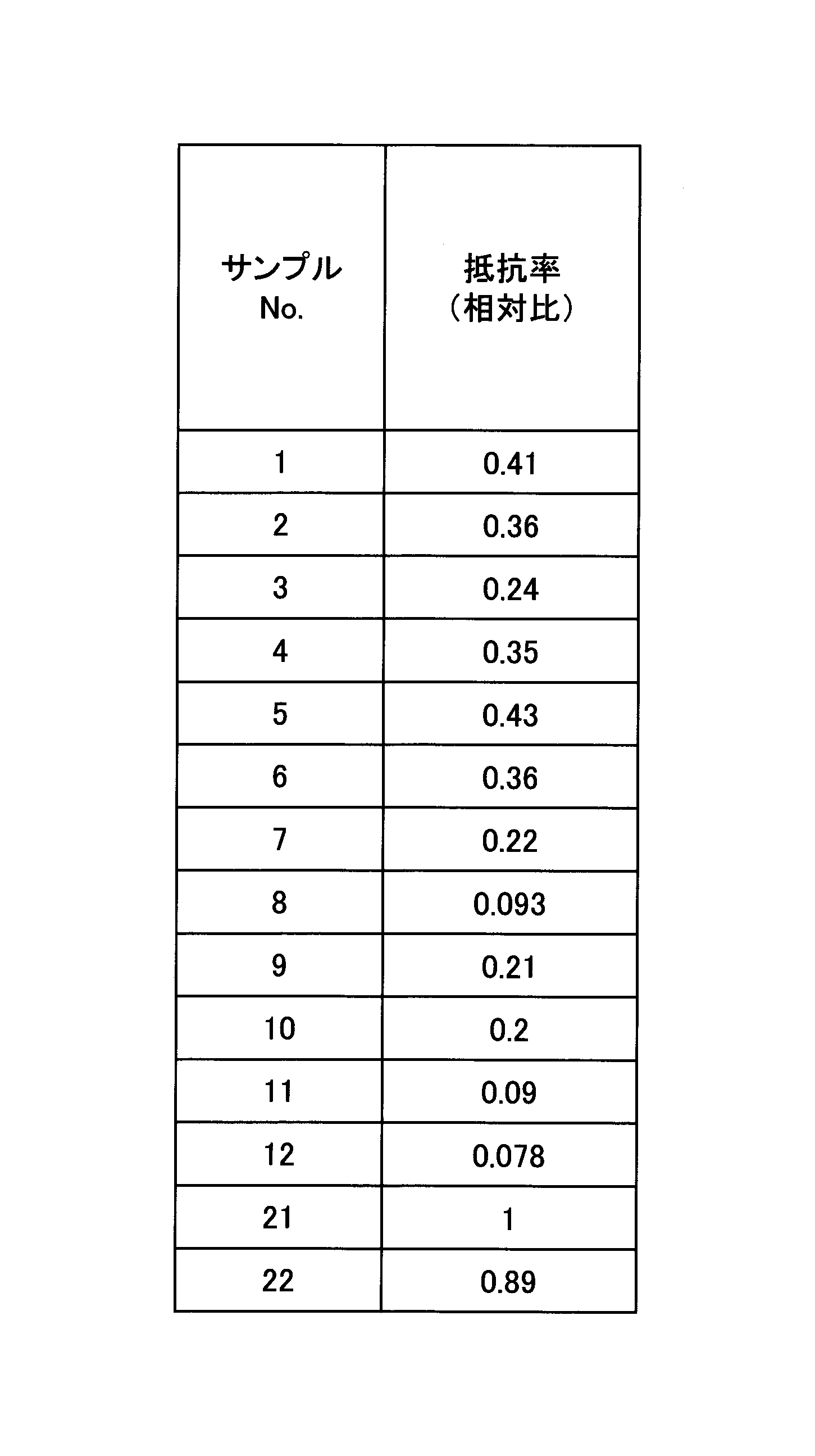
この結果から、サンプル22の抵抗率は、0.89であり、金属Mを含まないマイエナイト型化合物であるサンプル21と比べて、あまり抵抗率が低下していないことがわかった。
From this result, it was found that the resistivity of sample 22 was 0.89, and that the resistivity did not decrease much compared to sample 21, which is a mayenite type compound containing no metal M.
本発明は、以下の態様を含む。 (Aspect of the present invention)
The present invention includes the following aspects.
酸化物イオン伝導性固体電解質であって、
Ca12Al14O33で表される代表組成を有するマイエナイト型化合物を有し、
ランタン(La)およびイットリウム(Y)から選ばれた少なとも1種の金属元素Mを有し、
前記金属元素Mは、当該酸化物イオン伝導性固体電解質の全体に対して、酸化物換算で0.4モル%~5.3モル%の範囲で含まれる、酸化物イオン伝導性固体電解質。 (Aspect 1)
An oxide ion conductive solid electrolyte,
Having a mayenite type compound having a representative composition represented by Ca 12 Al 14 O 33 ,
Having at least one metal element M selected from lanthanum (La) and yttrium (Y),
The oxide ion conductive solid electrolyte, wherein the metal element M is contained in a range of 0.4 mol % to 5.3 mol % in terms of oxide with respect to the entire oxide ion conductive solid electrolyte.
前記金属元素Mは、前記マイエナイト型化合物中に含有されている、態様1に記載の酸化物イオン伝導性固体電解質。 (Aspect 2)
The oxide ion conductive solid electrolyte according to aspect 1, wherein the metal element M is contained in the mayenite type compound.
前記金属元素Mは、前記マイエナイト型化合物におけるCa原子のサイトに配置されている、態様2に記載の酸化物イオン伝導性固体電解質。 (Aspect 3)
The oxide ion conductive solid electrolyte according to aspect 2, wherein the metal element M is arranged at a Ca atom site in the mayenite compound.
Ca原子に対する前記金属元素Mのモル比(M/Ca)は、0.015≦M/Ca≦0.19を満たす、態様1乃至3のいずれか一つに記載の酸化物イオン伝導性固体電解質。 (Aspect 4)
The oxide ion conductive solid electrolyte according to any one of aspects 1 to 3, wherein the molar ratio (M/Ca) of the metal element M to Ca atoms satisfies 0.015≦M/Ca≦0.19. .
さらに、チタン(Ti)を、TiO2換算で0.1モル%~30モル%含む、態様1乃至4のいずれか一つに記載の酸化物イオン伝導性固体電解質。 (Aspect 5)
5. The oxide ion conductive solid electrolyte according to any one of aspects 1 to 4, further comprising 0.1 mol % to 30 mol % of titanium (Ti) in terms of TiO 2 .
前記Tiは、前記マイエナイト型化合物におけるAl原子のサイトに配置されている、態様5に記載の酸化物イオン伝導性固体電解質。 (Aspect 6)
The oxide ion conductive solid electrolyte according to aspect 5, wherein the Ti is arranged at the Al atom site in the mayenite type compound.
0.84≦(M+Ca)/Al≦0.88を満たす、態様1乃至6のいずれか一つに記載の酸化物イオン伝導性固体電解質。 (Aspect 7)
7. The oxide ion conductive solid electrolyte according to any one of aspects 1 to 6, which satisfies 0.84≦(M+Ca)/Al≦0.88.
態様1乃至7のいずれか一つに記載の酸化物イオン伝導性固体電解質を備える燃料電池セル。 (Aspect 8)
A fuel cell comprising the oxide ion conductive solid electrolyte according to any one of aspects 1 to 7.
態様1乃至7のいずれか一つに記載の酸化物イオン伝導性固体電解質を備える電解セル。 (Aspect 9)
An electrolytic cell comprising the oxide ion conductive solid electrolyte according to any one of aspects 1 to 7.
110 酸素極
120 燃料極
130 固体電解質層
140 外部負荷
200 SOECセル
210 酸素極
220 水素極
230 固体電解質層
240 外部電源 100 SOFC cell 110 oxygen electrode 120 fuel electrode 130 solid electrolyte layer 140 external load 200 SOEC cell 210 oxygen electrode 220 hydrogen electrode 230 solid electrolyte layer 240 external power supply
Claims (9)
- 酸化物イオン伝導性固体電解質であって、
Ca12Al14O33で表される代表組成を有するマイエナイト型化合物を有し、
ランタン(La)およびイットリウム(Y)から選ばれた少なとも1種の金属元素Mを有し、
前記金属元素Mは、当該酸化物イオン伝導性固体電解質の全体に対して、酸化物換算で0.4モル%~5.3モル%の範囲で含まれる、酸化物イオン伝導性固体電解質。 An oxide ion conductive solid electrolyte,
Having a mayenite type compound having a representative composition represented by Ca 12 Al 14 O 33 ,
Having at least one metal element M selected from lanthanum (La) and yttrium (Y),
The oxide ion conductive solid electrolyte, wherein the metal element M is contained in a range of 0.4 mol % to 5.3 mol % in terms of oxide with respect to the entire oxide ion conductive solid electrolyte. - 前記金属元素Mは、前記マイエナイト型化合物中に含有されている、請求項1に記載の酸化物イオン伝導性固体電解質。 The oxide ion conductive solid electrolyte according to claim 1, wherein the metal element M is contained in the mayenite compound.
- 前記金属元素Mは、前記マイエナイト型化合物におけるCa原子のサイトに配置されている、請求項2に記載の酸化物イオン伝導性固体電解質。 The oxide ion conductive solid electrolyte according to claim 2, wherein the metal element M is arranged at the site of the Ca atom in the mayenite compound.
- Ca原子に対する前記金属元素Mのモル比(M/Ca)は、0.015≦M/Ca≦0.19を満たす、請求項1または2に記載の酸化物イオン伝導性固体電解質。 3. The oxide ion conductive solid electrolyte according to claim 1 or 2, wherein the molar ratio (M/Ca) of said metal element M to Ca atoms satisfies 0.015≤M/Ca≤0.19.
- さらに、チタン(Ti)を、TiO2換算で0.1モル%~30モル%含む、請求項1または2に記載の酸化物イオン伝導性固体電解質。 3. The oxide ion conductive solid electrolyte according to claim 1, further comprising 0.1 mol % to 30 mol % of titanium (Ti) in terms of TiO 2 .
- 前記Tiは、前記マイエナイト型化合物におけるAl原子のサイトに配置されている、請求項5に記載の酸化物イオン伝導性固体電解質。 The oxide ion conductive solid electrolyte according to claim 5, wherein the Ti is arranged at the Al atom sites in the mayenite compound.
- 0.84≦(M+Ca)/Al≦0.88を満たす、請求項1または2に記載の酸化物イオン伝導性固体電解質。 3. The oxide ion conductive solid electrolyte according to claim 1, which satisfies 0.84≤(M+Ca)/Al≤0.88.
- 請求項1または2に記載の酸化物イオン伝導性固体電解質を備える燃料電池セル。 A fuel cell comprising the oxide ion conductive solid electrolyte according to claim 1 or 2.
- 請求項1または2に記載の酸化物イオン伝導性固体電解質を備える電解セル。 An electrolytic cell comprising the oxide ion conductive solid electrolyte according to claim 1 or 2.
Priority Applications (1)
| Application Number | Priority Date | Filing Date | Title |
|---|---|---|---|
| JP2023545182A JPWO2023032584A1 (en) | 2021-09-01 | 2022-08-04 |
Applications Claiming Priority (2)
| Application Number | Priority Date | Filing Date | Title |
|---|---|---|---|
| JP2021142548 | 2021-09-01 | ||
| JP2021-142548 | 2021-09-01 |
Publications (1)
| Publication Number | Publication Date |
|---|---|
| WO2023032584A1 true WO2023032584A1 (en) | 2023-03-09 |
Family
ID=85410982
Family Applications (1)
| Application Number | Title | Priority Date | Filing Date |
|---|---|---|---|
| PCT/JP2022/029929 WO2023032584A1 (en) | 2021-09-01 | 2022-08-04 | Oxide ion-conducting solid electrolyte |
Country Status (2)
| Country | Link |
|---|---|
| JP (1) | JPWO2023032584A1 (en) |
| WO (1) | WO2023032584A1 (en) |
Citations (7)
| Publication number | Priority date | Publication date | Assignee | Title |
|---|---|---|---|---|
| JP2003128415A (en) * | 2001-10-18 | 2003-05-08 | Japan Science & Technology Corp | 12CaO-7Al2O3 COMPOUND AND METHOD FOR PREPARING THE SAME |
| JP2007031248A (en) * | 2005-07-29 | 2007-02-08 | Oxy Japan:Kk | Substance including negatively charged oxygen atom, and method for producing the same |
| JP2007077280A (en) * | 2005-09-14 | 2007-03-29 | Ulvac Japan Ltd | Phosphor for electron beam-exciting light-emitting element, method for preparing the same and electron beam-exciting light-emitting element |
| KR101323098B1 (en) * | 2013-04-12 | 2013-10-30 | 한국세라믹기술원 | Manufacturing method of mayenite electride with improved electric conductivity |
| JP2014055313A (en) * | 2012-09-11 | 2014-03-27 | Tokyo Institute Of Technology | Mayenite composite material and electron emitting negative electrode |
| WO2019189701A1 (en) * | 2018-03-29 | 2019-10-03 | 国立大学法人東京工業大学 | Electrolytic cell and electrolytic device |
| JP2021142548A (en) | 2020-03-12 | 2021-09-24 | 久雄 石川 | Solder, method for producing solder and soldering component |
-
2022
- 2022-08-04 WO PCT/JP2022/029929 patent/WO2023032584A1/en active Application Filing
- 2022-08-04 JP JP2023545182A patent/JPWO2023032584A1/ja active Pending
Patent Citations (7)
| Publication number | Priority date | Publication date | Assignee | Title |
|---|---|---|---|---|
| JP2003128415A (en) * | 2001-10-18 | 2003-05-08 | Japan Science & Technology Corp | 12CaO-7Al2O3 COMPOUND AND METHOD FOR PREPARING THE SAME |
| JP2007031248A (en) * | 2005-07-29 | 2007-02-08 | Oxy Japan:Kk | Substance including negatively charged oxygen atom, and method for producing the same |
| JP2007077280A (en) * | 2005-09-14 | 2007-03-29 | Ulvac Japan Ltd | Phosphor for electron beam-exciting light-emitting element, method for preparing the same and electron beam-exciting light-emitting element |
| JP2014055313A (en) * | 2012-09-11 | 2014-03-27 | Tokyo Institute Of Technology | Mayenite composite material and electron emitting negative electrode |
| KR101323098B1 (en) * | 2013-04-12 | 2013-10-30 | 한국세라믹기술원 | Manufacturing method of mayenite electride with improved electric conductivity |
| WO2019189701A1 (en) * | 2018-03-29 | 2019-10-03 | 国立大学法人東京工業大学 | Electrolytic cell and electrolytic device |
| JP2021142548A (en) | 2020-03-12 | 2021-09-24 | 久雄 石川 | Solder, method for producing solder and soldering component |
Non-Patent Citations (5)
| Title |
|---|
| A. PEDONE ET AL., J. PHYS. CHEM. B, vol. 110, 2006, pages 11780 - 11795 |
| ALI M. MOZAHAR, NAGAO MASANORI, WATAUCHI SATOSHI, TANAKA ISAO: "Floating Zone Growth and Characterization of (Ca 1– x Nd x ) 12 Al 14 O 33+6 x ( x ∼ 0.001) Single Crystals", ACS OMEGA, ACS PUBLICATIONS, US, vol. 1, no. 6, 31 December 2016 (2016-12-31), US , pages 1157 - 1163, XP093042955, ISSN: 2470-1343, DOI: 10.1021/acsomega.6b00409 * |
| F.M. LEAC.H. DESCH: "The Chemistry of Cement and Concrete", 1956, EDWARD ARNOLD CO, pages: 52 |
| L.B. SKINNER ET AL., PHYS. REV. LETT., vol. 112, 2014, pages 157801 |
| M. LACERDA ET AL.: "High Oxide ion conductivity in Cai Al O", NATURE, vol. 332, 7 April 1988 (1988-04-07), pages 525, XP002558548, DOI: 10.1038/332525a0 |
Also Published As
| Publication number | Publication date |
|---|---|
| JPWO2023032584A1 (en) | 2023-03-09 |
Similar Documents
| Publication | Publication Date | Title |
|---|---|---|
| Xia et al. | Natural mineral-based solid oxide fuel cell with heterogeneous nanocomposite derived from hematite and rare-earth minerals | |
| Ding et al. | High reactive Ce0. 8Sm0. 2O1. 9 powders via a carbonate co-precipitation method as electrolytes for low-temperature solid oxide fuel cells | |
| JP5642197B2 (en) | Composite ceramic material and method for producing the same | |
| Zhang et al. | Sinterability and ionic conductivity of coprecipitated Ce0. 8Gd0. 2O2− δ powders treated via a high-energy ball-milling process | |
| JP6655122B2 (en) | Method for producing proton conductive oxide fuel cell | |
| KR101808387B1 (en) | Ceria electrolyte for low temperature sintering and solid oxide fuel cells using the same | |
| Chen et al. | Ca and Fe co-doped NdBaCo2O5+ δ double perovskites as high-performance cathodes for solid oxide fuel cells | |
| Bucevac et al. | Effect of preparation route on the microstructure and electrical conductivity of co-doped ceria | |
| Tok et al. | Consolidation and properties of Gd0. 1Ce0. 9O1. 95 nanoparticles for solid-oxide fuel cell electrolytes | |
| Wang et al. | Stable, easily sintered Ca–Zn-doped YCrO3 as novel interconnect materials for co-fired yttrium-stabilized zirconia-based solid oxide fuel cells | |
| Kobayashi et al. | Sinterable powder fabrication of lanthanum silicate oxyapatite based on solid-state reaction method | |
| Lu et al. | Modified Pechini synthesis and characterization of Y-doped strontium titanate perovskite | |
| WO2023032584A1 (en) | Oxide ion-conducting solid electrolyte | |
| WO2023079892A1 (en) | Oxide ion–conducting solid electrolyte | |
| WO2023032787A1 (en) | Oxide ion conductive solid electrolyte | |
| JP4889166B2 (en) | Low-temperature sinterable solid electrolyte material, electrolyte electrode assembly and solid oxide fuel cell using the same | |
| Cheng et al. | Effects of Mg2+ addition on structure and electrical properties of gadolinium doped ceria electrolyte ceramics | |
| West et al. | Improved phase stability and electrochemical performance of (Y, In, Ca) BaCo3ZnO7+ δ cathodes for intermediate temperature solid oxide fuel cells | |
| WO2023079877A1 (en) | Oxide ion–conducting solid electrolyte | |
| Hwan Jo et al. | Low-temperature sintering of dense lanthanum silicate electrolytes with apatite-type structure using an organic precipitant synthesized nanopowder | |
| WO2023079910A1 (en) | Oxide ion–conducting solid electrolyte | |
| JP2003123789A (en) | Solid electrolyte material, its manufacturing method, and solid electrolyte fuel cell using the same | |
| WO2022230686A1 (en) | Oxide ion-conducting solid electrolyte | |
| JP2023035580A (en) | Oxide ion conducting solid electrolyte | |
| Cheng et al. | Preparation and electrical properties of gadolinium-doped strontium tungstate electrolyte for SOFC |
Legal Events
| Date | Code | Title | Description |
|---|---|---|---|
| 121 | Ep: the epo has been informed by wipo that ep was designated in this application |
Ref document number: 22864170 Country of ref document: EP Kind code of ref document: A1 |
|
| WWE | Wipo information: entry into national phase |
Ref document number: 2023545182 Country of ref document: JP |
|
| WWE | Wipo information: entry into national phase |
Ref document number: 2022864170 Country of ref document: EP |
|
| NENP | Non-entry into the national phase |
Ref country code: DE |
|
| ENP | Entry into the national phase |
Ref document number: 2022864170 Country of ref document: EP Effective date: 20240402 |