EP4398056A1 - Management system - Google Patents
Management system Download PDFInfo
- Publication number
- EP4398056A1 EP4398056A1 EP22864772.3A EP22864772A EP4398056A1 EP 4398056 A1 EP4398056 A1 EP 4398056A1 EP 22864772 A EP22864772 A EP 22864772A EP 4398056 A1 EP4398056 A1 EP 4398056A1
- Authority
- EP
- European Patent Office
- Prior art keywords
- information
- box
- mark
- molding member
- database
- Prior art date
- Legal status (The legal status is an assumption and is not a legal conclusion. Google has not performed a legal analysis and makes no representation as to the accuracy of the status listed.)
- Pending
Links
Images















Classifications
-
- G—PHYSICS
- G06—COMPUTING OR CALCULATING; COUNTING
- G06K—GRAPHICAL DATA READING; PRESENTATION OF DATA; RECORD CARRIERS; HANDLING RECORD CARRIERS
- G06K7/00—Methods or arrangements for sensing record carriers, e.g. for reading patterns
- G06K7/10—Methods or arrangements for sensing record carriers, e.g. for reading patterns by electromagnetic radiation, e.g. optical sensing; by corpuscular radiation
- G06K7/10544—Methods or arrangements for sensing record carriers, e.g. for reading patterns by electromagnetic radiation, e.g. optical sensing; by corpuscular radiation by scanning of the records by radiation in the optical part of the electromagnetic spectrum
- G06K7/10712—Fixed beam scanning
- G06K7/10722—Photodetector array or CCD scanning
-
- B—PERFORMING OPERATIONS; TRANSPORTING
- B22—CASTING; POWDER METALLURGY
- B22D—CASTING OF METALS; CASTING OF OTHER SUBSTANCES BY THE SAME PROCESSES OR DEVICES
- B22D17/00—Pressure die casting or injection die casting, i.e. casting in which the metal is forced into a mould under high pressure
- B22D17/20—Accessories: Details
- B22D17/32—Controlling equipment
-
- B—PERFORMING OPERATIONS; TRANSPORTING
- B22—CASTING; POWDER METALLURGY
- B22D—CASTING OF METALS; CASTING OF OTHER SUBSTANCES BY THE SAME PROCESSES OR DEVICES
- B22D18/00—Pressure casting; Vacuum casting
- B22D18/02—Pressure casting making use of mechanical pressure devices, e.g. cast-forging
-
- B—PERFORMING OPERATIONS; TRANSPORTING
- B22—CASTING; POWDER METALLURGY
- B22D—CASTING OF METALS; CASTING OF OTHER SUBSTANCES BY THE SAME PROCESSES OR DEVICES
- B22D46/00—Controlling, supervising, not restricted to casting covered by a single main group, e.g. for safety reasons
-
- B—PERFORMING OPERATIONS; TRANSPORTING
- B29—WORKING OF PLASTICS; WORKING OF SUBSTANCES IN A PLASTIC STATE IN GENERAL
- B29C—SHAPING OR JOINING OF PLASTICS; SHAPING OF MATERIAL IN A PLASTIC STATE, NOT OTHERWISE PROVIDED FOR; AFTER-TREATMENT OF THE SHAPED PRODUCTS, e.g. REPAIRING
- B29C45/00—Injection moulding, i.e. forcing the required volume of moulding material through a nozzle into a closed mould; Apparatus therefor
- B29C45/17—Component parts, details or accessories; Auxiliary operations
- B29C45/1769—Handling of moulded articles or runners, e.g. sorting, stacking, grinding of runners
-
- B—PERFORMING OPERATIONS; TRANSPORTING
- B29—WORKING OF PLASTICS; WORKING OF SUBSTANCES IN A PLASTIC STATE IN GENERAL
- B29C—SHAPING OR JOINING OF PLASTICS; SHAPING OF MATERIAL IN A PLASTIC STATE, NOT OTHERWISE PROVIDED FOR; AFTER-TREATMENT OF THE SHAPED PRODUCTS, e.g. REPAIRING
- B29C45/00—Injection moulding, i.e. forcing the required volume of moulding material through a nozzle into a closed mould; Apparatus therefor
- B29C45/17—Component parts, details or accessories; Auxiliary operations
- B29C45/76—Measuring, controlling or regulating
-
- B—PERFORMING OPERATIONS; TRANSPORTING
- B29—WORKING OF PLASTICS; WORKING OF SUBSTANCES IN A PLASTIC STATE IN GENERAL
- B29C—SHAPING OR JOINING OF PLASTICS; SHAPING OF MATERIAL IN A PLASTIC STATE, NOT OTHERWISE PROVIDED FOR; AFTER-TREATMENT OF THE SHAPED PRODUCTS, e.g. REPAIRING
- B29C45/00—Injection moulding, i.e. forcing the required volume of moulding material through a nozzle into a closed mould; Apparatus therefor
- B29C45/17—Component parts, details or accessories; Auxiliary operations
- B29C45/76—Measuring, controlling or regulating
- B29C45/7686—Measuring, controlling or regulating the ejected articles, e.g. weight control
-
- G—PHYSICS
- G05—CONTROLLING; REGULATING
- G05B—CONTROL OR REGULATING SYSTEMS IN GENERAL; FUNCTIONAL ELEMENTS OF SUCH SYSTEMS; MONITORING OR TESTING ARRANGEMENTS FOR SUCH SYSTEMS OR ELEMENTS
- G05B19/00—Program-control systems
- G05B19/02—Program-control systems electric
- G05B19/418—Total factory control, i.e. centrally controlling a plurality of machines, e.g. direct or distributed numerical control [DNC], flexible manufacturing systems [FMS], integrated manufacturing systems [IMS] or computer integrated manufacturing [CIM]
- G05B19/4183—Total factory control, i.e. centrally controlling a plurality of machines, e.g. direct or distributed numerical control [DNC], flexible manufacturing systems [FMS], integrated manufacturing systems [IMS] or computer integrated manufacturing [CIM] characterised by data acquisition, e.g. workpiece identification
-
- G—PHYSICS
- G05—CONTROLLING; REGULATING
- G05B—CONTROL OR REGULATING SYSTEMS IN GENERAL; FUNCTIONAL ELEMENTS OF SUCH SYSTEMS; MONITORING OR TESTING ARRANGEMENTS FOR SUCH SYSTEMS OR ELEMENTS
- G05B19/00—Program-control systems
- G05B19/02—Program-control systems electric
- G05B19/418—Total factory control, i.e. centrally controlling a plurality of machines, e.g. direct or distributed numerical control [DNC], flexible manufacturing systems [FMS], integrated manufacturing systems [IMS] or computer integrated manufacturing [CIM]
- G05B19/41875—Total factory control, i.e. centrally controlling a plurality of machines, e.g. direct or distributed numerical control [DNC], flexible manufacturing systems [FMS], integrated manufacturing systems [IMS] or computer integrated manufacturing [CIM] characterised by quality surveillance of production
-
- G—PHYSICS
- G06—COMPUTING OR CALCULATING; COUNTING
- G06K—GRAPHICAL DATA READING; PRESENTATION OF DATA; RECORD CARRIERS; HANDLING RECORD CARRIERS
- G06K7/00—Methods or arrangements for sensing record carriers, e.g. for reading patterns
- G06K7/10—Methods or arrangements for sensing record carriers, e.g. for reading patterns by electromagnetic radiation, e.g. optical sensing; by corpuscular radiation
- G06K7/14—Methods or arrangements for sensing record carriers, e.g. for reading patterns by electromagnetic radiation, e.g. optical sensing; by corpuscular radiation using light without selection of wavelength, e.g. sensing reflected white light
- G06K7/1404—Methods for optical code recognition
- G06K7/1408—Methods for optical code recognition the method being specifically adapted for the type of code
- G06K7/1413—1D bar codes
-
- G—PHYSICS
- G06—COMPUTING OR CALCULATING; COUNTING
- G06K—GRAPHICAL DATA READING; PRESENTATION OF DATA; RECORD CARRIERS; HANDLING RECORD CARRIERS
- G06K7/00—Methods or arrangements for sensing record carriers, e.g. for reading patterns
- G06K7/10—Methods or arrangements for sensing record carriers, e.g. for reading patterns by electromagnetic radiation, e.g. optical sensing; by corpuscular radiation
- G06K7/14—Methods or arrangements for sensing record carriers, e.g. for reading patterns by electromagnetic radiation, e.g. optical sensing; by corpuscular radiation using light without selection of wavelength, e.g. sensing reflected white light
- G06K7/1404—Methods for optical code recognition
- G06K7/1408—Methods for optical code recognition the method being specifically adapted for the type of code
- G06K7/1417—2D bar codes
-
- G—PHYSICS
- G06—COMPUTING OR CALCULATING; COUNTING
- G06V—IMAGE OR VIDEO RECOGNITION OR UNDERSTANDING
- G06V10/00—Arrangements for image or video recognition or understanding
- G06V10/10—Image acquisition
-
- G—PHYSICS
- G06—COMPUTING OR CALCULATING; COUNTING
- G06V—IMAGE OR VIDEO RECOGNITION OR UNDERSTANDING
- G06V20/00—Scenes; Scene-specific elements
- G06V20/60—Type of objects
- G06V20/62—Text, e.g. of license plates, overlay texts or captions on TV images
- G06V20/63—Scene text, e.g. street names
-
- B—PERFORMING OPERATIONS; TRANSPORTING
- B29—WORKING OF PLASTICS; WORKING OF SUBSTANCES IN A PLASTIC STATE IN GENERAL
- B29C—SHAPING OR JOINING OF PLASTICS; SHAPING OF MATERIAL IN A PLASTIC STATE, NOT OTHERWISE PROVIDED FOR; AFTER-TREATMENT OF THE SHAPED PRODUCTS, e.g. REPAIRING
- B29C2945/00—Indexing scheme relating to injection moulding, i.e. forcing the required volume of moulding material through a nozzle into a closed mould
- B29C2945/76—Measuring, controlling or regulating
- B29C2945/76451—Measurement means
- B29C2945/76461—Optical, e.g. laser
- B29C2945/76464—Optical, e.g. laser cameras
-
- B—PERFORMING OPERATIONS; TRANSPORTING
- B29—WORKING OF PLASTICS; WORKING OF SUBSTANCES IN A PLASTIC STATE IN GENERAL
- B29C—SHAPING OR JOINING OF PLASTICS; SHAPING OF MATERIAL IN A PLASTIC STATE, NOT OTHERWISE PROVIDED FOR; AFTER-TREATMENT OF THE SHAPED PRODUCTS, e.g. REPAIRING
- B29C2945/00—Indexing scheme relating to injection moulding, i.e. forcing the required volume of moulding material through a nozzle into a closed mould
- B29C2945/76—Measuring, controlling or regulating
- B29C2945/76822—Phase or stage of control
- B29C2945/76899—Removing or handling ejected articles
-
- B—PERFORMING OPERATIONS; TRANSPORTING
- B29—WORKING OF PLASTICS; WORKING OF SUBSTANCES IN A PLASTIC STATE IN GENERAL
- B29C—SHAPING OR JOINING OF PLASTICS; SHAPING OF MATERIAL IN A PLASTIC STATE, NOT OTHERWISE PROVIDED FOR; AFTER-TREATMENT OF THE SHAPED PRODUCTS, e.g. REPAIRING
- B29C2945/00—Indexing scheme relating to injection moulding, i.e. forcing the required volume of moulding material through a nozzle into a closed mould
- B29C2945/76—Measuring, controlling or regulating
- B29C2945/76929—Controlling method
-
- G—PHYSICS
- G06—COMPUTING OR CALCULATING; COUNTING
- G06V—IMAGE OR VIDEO RECOGNITION OR UNDERSTANDING
- G06V2201/00—Indexing scheme relating to image or video recognition or understanding
- G06V2201/02—Recognising information on displays, dials, clocks
-
- Y—GENERAL TAGGING OF NEW TECHNOLOGICAL DEVELOPMENTS; GENERAL TAGGING OF CROSS-SECTIONAL TECHNOLOGIES SPANNING OVER SEVERAL SECTIONS OF THE IPC; TECHNICAL SUBJECTS COVERED BY FORMER USPC CROSS-REFERENCE ART COLLECTIONS [XRACs] AND DIGESTS
- Y02—TECHNOLOGIES OR APPLICATIONS FOR MITIGATION OR ADAPTATION AGAINST CLIMATE CHANGE
- Y02P—CLIMATE CHANGE MITIGATION TECHNOLOGIES IN THE PRODUCTION OR PROCESSING OF GOODS
- Y02P90/00—Enabling technologies with a potential contribution to greenhouse gas [GHG] emissions mitigation
- Y02P90/30—Computing systems specially adapted for manufacturing
Definitions
- the present invention relates to a control system, e.g., a control system for a molding member.
- the present invention is conceived under circumstances as described above, and an object of the present invention is to control a molding member in unit of a returnable box.
- one mark reading portion 140 may have a field of view which allows the mark reading portion 140 to pick up the plurality of pickup positions.
- the mark reading portion 140 may be configured that one mark reading portion 140 shall move to the plurality of pickup positions, or a plurality of mark reading portions 140 shall move to pick up positions within a certain defined range.
- various combinations may be applied.
- the mark reading portion 140 picks up the operating screen 100b at the position for reading and picking up the kind 40a.
- the image picked up by the mark reading portion 140 is transmitted to the image analyzing portion 150.
- Part (b) of Figure 2 is a view illustrating an image processing screen 150a of the image analyzing portion 150, and is a schematic view illustrating an image processing which analyzes information on the kind (hereinafter referred to as "kind information") from the picked up operating screen 100b of the injection molding machine 100.
- the operating screen 100b is displayed on the image processing screen 150a of the image analyzing portion 150.
- the image analyzing portion 150 can then identify the current kind of the molding member by capturing a molding condition name 11 within an image processing area 150b and performing the image processing.
- a program of the image processing it is necessary for a program of the image processing to be constructed and registered in advance in a storage portion (not shown), which is provided to the image analyzing portion 150, so that the kind information of the molding member 10 can be read from the molding condition name 11.
- a rule is defined that a name of the kind of the molding member 10 (hereinafter referred to as "kind name”) should be disposed at a right end of the molding condition name 11, and a program for reading a character at the right end of the image processing area 150b is developed.
- the image analyzing portion 150 performs the image processing of an image within the image processing area 150b and determines the kind of the molding member 10 to be, for example, "A”.
- a location for identifying the kind is not limited to the location of the molding condition name 11, but may be positions of other information displayed on the operating screen 100b, such as a molding temperature 12 (°C), molding condition 13, etc.
- the operating screen 100b which is provided to the injection molding machine 100, serves as a first display portion for displaying information on at least the kind of the molding member.
- the robot for taking out the molding member 102 may also serve as the robot for storing the molding member 110b.
- Part (a) of Figure 4 is a schematic view illustrating a partition 23a of the returnable box 20a and a mark 400a on a lid 21a.
- the returnable box 20a is provided with the partition 23a so that the molding members 10 can be stored in an aligned manner.
- the returnable box 20a is made of plastic in terms of conveyance, rigidity, etc., and a plurality of returnable boxes 20a of the same shape are used to store a large quantity of the molding members 10.
- the returnable box 20a does not have to be provided with the partition 23a, nor does it have to be made of plastic.
- the mark 400a is attached, which is a first mark indicating information on the box for identifying each returnable box 20a.
- the returnable box 20a is provided with the partition 23a to store, for example, the sixteen molding members 10 inside.
- the molding/storing of the molding member 10 is repeated in this manner, and when the returnable box 20a becomes full, the lid 21a is put on an opening of the returnable box 20a.
- the lid 21a includes the mark 400a as shown in part (a) of Figure 4 and is configured to be separate from the returnable box 20a, however, the lid 21a may be configured to be integral with the returnable box 20a.
- part (b) of Figure 4 is a schematic view illustrating other marks, i.e., modified examples of the first mark.
- the mark 400a for example, a two-dimensional code is used, however, as shown in part (b) of Figure 4 , a one-dimensional bar code, a symbol or a number, each of which can be identified, Data Matrix, which is another two-dimensional code, etc., may be used as long as each of these can be identified.
- the first mark (mark 400a) may include a character, a graphic, a symbol, a color, a one-dimensional bar code or a two-dimensional code, or a combination thereof.
- the mark reading portion 140 is fixedly or movably set at the position for reading and picking up the finished product 40b, which is a position where the mark 400a, which is attached to the lid 21a of the returnable box 20a placed at the packing completion position 110d, can be picked up.
- the position for reading and picking up the finished product 40b shall be registered in the storage portion (not shown) in advance.
- Part (b) of Figure 5 is a view illustrating the image processing screen 150a of the image analyzing portion 150, and is a schematic view illustrating a state of the image processing which reads the mark 400a.
- the mark 400a is displayed on the image processing screen 150a of the image analyzing portion 150.
- the image analyzing portion 150 then captures the mark 400a in the image processing area 150c, recognizes the mark 400a by the image processing, and transmits information that the molding member 10 is stored in the returnable box 20a to which the mark 400a is attached to the record controlling portion 130, and the record controlling portion 130 records the information.
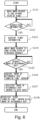
- Figure 6 is a flowchart illustrating a registration process to the database.
- FIG. 6 which illustrates a process for associating the returnable box, the kind of the molding member and the completion time of packing by the system side S2
- S 101 a step 101
- the system side S2 moves the mark reading portion 140 to the position for reading and picking up the kind 40a.
- the system side S2 picks up the operating screen 100b of the injection molding machine 100 by the mark reading portion 140 and determines whether or not the kind information of the molding member 10 has been searched by the image analyzing portion 150.
- the search includes that the image analyzing portion 150 captures the targeted molding condition name 11 of part (b) of Figure 2 , for example, within the image processing area 150c. If the system side S2 determines in S102 that the search for the kind information is not completed, then returns the process to S102 to continue the search, and if the system side S2 determines that the search is completed, then proceeds the process to S103.
- the system side S2 moves the mark reading portion 140 to the position for reading and picking up the finished product 40b.
- the system side S2 may move the mark reading portion 140 in advance to the position for reading and picking up the finished product 40b without waiting for the returnable box 20a to be transported to the packing completion position 110d.
- the system side S2 picks up the mark 400a of the returnable box 20a by the mark reading portion 140 and determines whether or not a search for the mark 400a by the image analyzing portion 150 is completed.
- the search includes that the image analyzing portion 150 captures the targeted mark 400a within the image processing area 150c.
- the system side S2 stores the time when the mark 400a is picked up by the mark reading portion 140 by the record controlling portion 130 in the storage portion (not shown) as the completion time of packing Ta. If the system side S2 determines in S105 that the search for the mark 400a is not completed, then returns the process to S105, and if the system side S2 determines that the search for the mark 400a is completed, then proceeds the process to S106.
- the system side S2 acquires information of the mark 400a searched in S 105 and the completion time of packing Ta stored in the storage portion (not shown).
- the system side S2 registers the mark 400a of the returnable box 20a to the database by the record controlling portion 130.
- the system side S2 associates the mark 400a of the returnable box 20a registered in the database with the kind information acquired in S 103 and the completion time of packing Ta acquired in S 106, registers these to the database, and ends the process.
- the various data collected by the image analyzing portion 150 is transmitted to the record controlling portion 130, which is connected via the LAN, association of the information is performed by the record controlling portion 130, and the database is constructed.
- Part (c) of Figure 5 is a view illustrating an example of the database at the packing completion position 110d.
- the data transmitted to the record controlling portion 130 are associated with each other in a database structure shown in part (c) of Figure 5 .
- one record is registered per mark number 1001.
- Each record has columns such as a bar code No. 1002, a kind 1003, an aging time 1004, a completion time 1005, a shipping availability 1006, and a priority order 1007, which are associated as attributes.
- the reference numeral "400a" of the mark 400a is used for the mark number 1001.
- the bar code No. 1002 is an unordered number indicating the mark 400a.
- the returnable boxes 20f through 20i store the molding members of the kind B, which are molded on the same day by the injection molding machine 100 and with which the information is associated through the same processes and operation (process 1 through process 6) as the kind A described above.
- an even greater number of returnable boxes may be placed, or even a greater number of kinds may be mixed.
- suffixes of reference numeral a, b..., etc. may be omitted except when describing a specific returnable box, etc.
- the shipping availability 1006 is "shipping unavailable”.
- information such as following is associated with the record of the mark number 1001 being "400g" and constructed as the database. That is, the bar code No. 1002 is "0032”, the kind 1003 is “B”, the aging time 1004 is “4" hours, the completion time 1005 is "2110090830”, and the shipping availability 1006 is "shipping unavailable”.
- the image analyzing portion 150 calculates positional information for displaying an image in a virtual space of the display unit 310 using a conversion formula to a virtual coordinate system prepared in advance.
- the positional information for displaying the image in the virtual space of the display unit (virtual coordinates) is hereinafter referred to as virtual positional information for display and is denoted by XX1 through XX9 and YY1 through YY9.
- the image analyzing portion 150 also determines presence or absence of the mark 400 as a result of the image analysis on the picked-up image of the inventory storage area 120. If the image analyzing portion 150 cannot find the mark 400a, then image analyzing portion 150 erases the information 410a indicating the mark 400a from the image processing screen 150a.
- Part (b) of Figure 11 is a schematic view illustrating the virtual inventory storage area 220 displayed on the display unit 310 corresponding to the state in part (a) of Figure 11 .
- the record controlling portion 130 updates the display of the display unit 310 as shown in part (b) of Figure 11 .
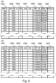
- Figure 12 is the database showing a state of part (b) of Figure 11 .
- the record controlling portion 130 updates the information in the database as shown in part (a) of Figure 12 .
- part (b) of Figure 15 is a view illustrating the database corresponding to the state of part (a) of Figure 15 .
- the inventory storage area 120a is picked up by the mark reading portion 140y, which is changing the pickup positions one after another from the pickup range 43a through 43f.
- the database of part (b) of Figure 15 is provided with columns for a bar code No. 1022 (e.g.
- the mark reading portion 140 picks up the inventory storage area 120 at the predetermined time interval at the position for reading and picking up the inventory storage area 40c.
- Part (a) of Figure 16 is a schematic view illustrating a status in which the returnable box 20a, which became empty, is returned to the inventory storage area 120. As shown in part (a) of Figure 16 , when the returnable box 20a is returned to the inventory storage area 120, it can be recognized that the mark 400a attached to the returnable box 20a appears in the inventory storage area 120 by the image analyzing portion 150 analyzing the image picked up by the mark reading portion 140. The image analyzing portion 150 transmits this information to the record controlling portion 130.
- part (b) of Figure 16 is a view illustrating another database for backup.
- the record controlling portion 130 may separately store the information as a backup in the storage portion (not shown) so that history of the mark 400a can be followed in the database.
- an erased time 1035, etc. may be provided to record the time when the returnable box 20a is returned with becoming empty to the inventory storage area 120, etc.
- Part (b) of Figure 18 is a schematic view of a case in which a mark 450p and a mark 400p are attached to a main body of a returnable box 20p and to a lid 21p, respectively, and a view illustrating an example of the database.
- the mark attached to the returnable box is not limited to one.
- the returnable box 20p is provided with the main body having an inner space for storing the molding member and the lid 21p, which is put on the main body.
- the mark 450p which is the first mark
- the mark 400p which is a third mark indicating information on the lid 21p
- the kind information may be incorporated.
- Figure 19A is a schematic view when marks 450q, 450r, 400q and 400r are attached to a plurality of the returnable boxes 20q and 20r and the lids 21q and 21r, respectively, and a view illustrating an example of the database.
- the database can be constructed for the returnable box 20q and the lid 21q and the returnable box 20r and the lid 21r as shown in Figure 19A .
- Figure 19B is a schematic view when the returnable box 20q and the returnable box 20r are stacked and a view illustrating an example of the database.
- the mark 400q attached to the lid 21q of the returnable box 20q becomes invisible.
- the mark 400q cannot be recognized by the image analyzing portion 150.
- the mark 400q on the downside lid 21q is invisible, since the mark 450q of the returnable box 20q is attached in a visible position, it is possible to acquire information on a status of the returnable box 20q from the mark 450q.
- the database by associating the information of the mark 400q with the mark 400r of the upside lid 21r.
- the database is constructed so that the records of the database are firstly divided into columns of a first row 1055 (top row) and a second row 1056, and then the mark number (lid) 1051 and 1053, and bar code No. 1052 and 1054 are given, respectively.
- first row (top row) 1055 "400r” is registered in the mark number (lid) 1051 and the bar code No. "2054" indicated by the mark 400r is registered in the bar code No. 1042, respectively.
- the second row 1056 "400q” is registered in the mark number (lid) 1053, and the bar code No. "1069” indicated by the mark 400q is registered in the bar code No. 1054, respectively.
- the kind of the molding member can also be determined based on the mold.
- the injection molding machine 100 may have the mold provided with a second mark which includes the information on the kind of the molding member.
- Part (a) of Figure 21 is a schematic view in a case that, to a mold 101d of the injection molding machine 100, the mark 470d, which is the second mark, is attached. Therefore, as shown in part (a) of Figure 21 , the mark 470d provided to the mold 101d can be picked up by the mark reading portion 140, and the kind of the molding member can be identified through the image analysis by the image analyzing portion 150. In addition, a shape of the molding member and a shape/color, etc.
- Part (b) of Figure 21 is a view illustrating an example of the database when the molding history information of the injection molding machine 100 is added.
- various information as shown in part (b) of Figure 21 may be added to the database shown in part (c) of Figure 5 .
- the molding history such as molding log like a molding condition 1060, a maximum injection pressure 1061, a cushion amount 1062, etc., may be extracted from the injection molding machine 100 and registered to the database.
- the general molding member is shipped after a predetermined inspection, e.g., the sampling inspection is executed.
- the configuration of the Embodiment 1 when a defect etc. occurs in the molding member, the returnable boxes to which the storing of the molding members have been completed before and after when the molding member with the defect is stored in a certain time range can be identified based on the information on the returnable box to which the molding member with the defect has been stored. And it becomes possible to compare the actual molded products molded before and after the defective product, and to efficiently identify the molding members to which the specific defect may occur without having to inspect all of the products, etc.
- the mark on the returnable box retains only the information which identifies the returnable box, unnecessary information is not recorded, and even in a case in which information is added, the addition is executed on the database associated with the mark, therefore there is no need for the mark of the returnable box to be transported in a writing device as well.
- the information on the kind of the molding member is acquired by picking up the operating screen 100b of the injection molding machine 100 with the mark reading portion 140 at the timing of molding the molding member with the injection molding machine 100.
- the information on the kind may be registered to the database by associating the information on the kind with the mark attached to the returnable box at a timing when the returnable box storing the molding member is placed in the inventory storage area.
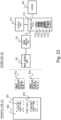
- FIG. 23 a configuration of a control system in the Embodiment 2 is shown in Figure 23 .
- An inventory storage area 620 is in the device side SS1, and in the system side SS2, the same devices as in the Embodiment 1 are used, and reference numerals are the reference numerals used in the Embodiment 1 added by one.
- a record controlling portion 131 MELSEC-Q series from Mitsubishi Heavy Industries, Ltd. is used.
- VB-H45 from Canon Inc., which is the NWC capable of pan, tilt and zoom, is used.
- As an image analyzing portion 151 Canon Industrial Imaging Platform (hereinafter, CIIP) Vision Edition (hereinafter VE) from Canon Inc. is used.
- CIIP Canon Industrial Imaging Platform
- VE Canon Inc.
- the round numbers are omitted, and the positions are distinguished by the reference numerals.
- the returnable box in which the molding member of the kind H is stored is placed at the stocking position 621, and the returnable box in which the molding member of the kind G is stored is placed at the stocking position 622.
- the returnable boxes may be placed separately for each kind.
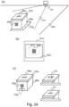
- Part (a) of Figure 24 is a schematic view illustrating a state in which a mark 550a and/or a mark 500a is read by the mark reading portion 141.
- a returnable box 200a in which the molding member is stored is transported to the inventory storage area 620.
- the mark reading portion 141 is fixedly set in a position where the mark reading portion 141 can pick up the mark 500a attached to a lid 210a of the returnable box 200a.
- the mark reading portion 141 may be movably set, and in this case, the positions described above shall be registered as pick up positions in advance.
- the mark reading portion 141 picks up a vicinity including the returnable box 200a at the position for picking up the stocking position 41a.
- Part (b) of Figure 24 is a view illustrating an image processing screen 151a of the image analyzing portion 151, and is a schematic view illustrating a state of an image processing when the mark 500a is read.
- An image picked up by the mark reading portion 141 is transmitted to the image analyzing portion 151 and, as shown in part (b) of Figure 24 , the mark 500a is displayed on the image processing screen 151a of the image analyzing portion 151.
- the image analyzing portion 151 recognizes the mark 500a by capturing the mark 500a in an image processing area 151c and applying the image processing thereto, and the record controlling portion 131 records information that the returnable box 200a provided with the mark 500a is stocked at the inventory storage area 620.
- time when the mark reading portion 141 picks up the mark 500a is defined as a completion time Tb.
- the returnable box in which the molding member of the kind H is stored is placed at the stocking position 621, and the returnable box in which the molding member of the kind G is stored is placed at the stocking position 622.
- the kind information of the molding member is acquired according to the pickup position of the mark reading portion 141.
- Part (c) of Figure 24 is a view illustrating another example showing the kind information.
- a kind information 510a on the kind stored in the returnable box 200a may be clearly marked on a main body (or lid 210a) of the returnable box 200a, for example, as "Kind: H".
- the kind information may be embedded in the mark 550a attached to the returnable box 200a which actually stores the molding member.
- a marking method of the mark 500a may be changed for each kind.
- it may be configured that the kind can be identified by making types of the mark different such that one kind is represented by a one-dimensional bar code 510, another kind is represented by a two-dimensional code 511.
- the kind information may be acquired from a configuration related to the injection molding machine.
- the position where the returnable box 200a (mark 500a) is placed/pickup position is the stocking position 621/position for picking up the stocking position 41a. Therefore, the record controlling portion 131 identifies the kind information of the molding member stored in the returnable box 200a (mark 500a) as "H" based on the positional information. At this time, a plurality of the returnable boxes may be placed at the stocking position 621 and the stocking position 622 and a plurality of the marks may be read.
- Part (a) of Figure 25 is a view illustrating an example of the database after the returnable box 200a is placed in the inventory storage area 620. Specifically, the information transmitted to the record controlling portion 131 is associated with the database shown in part (a) of Figure 25 , respectively.
- the database in part (a) of Figure 25 one record is registered for each mark number 1101. With each record, a bar code No. 1102, a kind 1103, an aging time 1104, a completion time 1105, a shipping availability 1106 and a priority order 1107 are associated as attributes.
- the reference numeral 500a of the mark is used for the mark number 1101.
- the completion time Tb is stored in the completion time 1105 in the record of the mark number 1101 being "500a”.
- the aging time T2 corresponding to the kind information is stored in the aging time 1104.
- the completion time 1105 shall be "2110101000”
- the aging time T2 for the kind H shall be five hours after completion of the stocking.
- the completion time 1105 is represented by a series of numbers for year (last two digits thereof), month, date, hour and minute, however, it may be changed according to data to be handled. In addition, there is a case that the aging time T2 varies depending on the kind of the molding member.
- the record controlling portion 131 stores the database on a server 301 connected via the LAN, etc., as appropriate.
- Figure 26 is a flowchart describing processes for registering the information on the returnable box of the Embodiment 2 to the database (database construction).
- the system side SS2 moves the mark reading portion 141 to the stocking position 621 or the stocking position 622.
- the process S201 may be skipped if the mark reading portion 141 is fixedly set at the stocking position 621 and the stocking position 622, respectively.
- the system side SS2 picks up the inventory storage area 620 by the mark reading portion 141, searches for the mark of the returnable box by analyzing the image by the image analyzing portion 151, and determines whether or not the search is completed. If the system side SS2 determines in S202 that the search is not completed, then returns the process to S202; and if the system side SS2 determines that the search is completed, then proceeds the process to S203.
- the system side SS2 records the time when the picking up is performed by the mark reading portion 141.
- the system side SS2 acquires the kind information of the molding member according to the stocking positions 621 and 622 or the positions for picking up the stocking position 41a and 41b. For example, if the mark reading portion 141 performs the picking up at the position for picking up the stocking position 41b, then the kind information is acquired as "G".
- the system side SS2 analyzes the mark of the returnable box by the image analyzing portion 151 as a result of the search in S201.
- the image analyzing portion 151 analyzes that the mark is "500a", and acquires the bar code No. of the mark 500a.
- the system side SS2 acquires the completion time, which is the time when the picking up is performed by the mark reading portion 141 in S202.
- the system side SS2 registers the mark "500a" acquired in S204 to the mark number 1101 in the database by the record controlling portion 131. Incidentally, in a case in which "500a" is already registered in the mark number 1101 of the database, the process S205 may be skipped.
- the system side SS2 registers the acquired information, etc. in the record of the mark number 1101 being "500a" in the database, associates the information on the returnable box with the information on the molding member, and terminates the process.
- the record controlling portion 131 registers the bar code No. acquired in S203 in the bar code No. 1102, the kind information acquired in S203 in the kind 1103, and the completion time acquired in S204 in the completion time 1105.
- a worker Y is notified of a transporting order of the returnable box 200a via a display unit 311, which is connected to the record controlling portion 131 via the LAN, the RS232C, etc.
- the worker Y transports the returnable box 200a from the stocking position 621 to arbitrary location in the inventory storage area 121.
- the stocking position 621 may also serve as an inventory storage area.
- Part (b) of Figure 25 is a schematic view illustrating a state in which the returnable boxes 200a through 200i are placed in the inventory storage area 620.
- nine boxes of the returnable boxes 200a through 200i are placed as shown in part (b) of Figure 25 .
- Arrangement of each box may be aligned as of the returnable box 200a of the mark 500a through the returnable box 200d of the mark 500d, or may be placed randomly as of the returnable box 200e of the mark 500e through the returnable box 200i of the mark 500i.
- it may be placed in the lattice-likely manner suitable for the free-location as described in the Embodiment 1.
- Process 4 and thereafter are the same as the process 7 and thereafter in the Embodiment 1.
- the Modified Examples described in the Embodiment 1 are also applicable to the Embodiment 2. Therefore, these descriptions will be omitted.
- the injection molding machine includes the mold, molds the molding member by a predetermined molding condition and a predetermined inner pressure in the mold and transmits molding history information including the molding condition and the inner pressure to a record controlling portion 132.
- the record controlling portion 132 associates the molding history information with the information on the returnable box in the database.
- the device side SSS 1 is constituted by an injection molding machine 900, a mold 901a, a robot for taking out the molding member 902a and a device for packing the molding member 910.
- the device for packing the molding member 910 includes a portion for handing over the molding member 910a and a robot for storing the molding member 910b.
- positions related to the device side SSS 1 there are an empty box standby position 910e, a packing position 910c, and a packing completion position 910d.
- the inventory storage area has the same configuration as the Embodiment 1 and the Embodiment 2.
- a system side SSS2 is constituted by a record controlling portion 132, a mark reading portion 142, an image analyzing portion 152, a server 302, a display unit 312 and an inner pressure amplifier 162.
- positions related to the system side SSS2 there is a position for reading and picking up the finished product 42b.
- the injection molding machine 900 and the robot for storing the molding member 910b are connected to the record controlling portion 132 via a network, etc.
- an inner pressure sensor 901b of the mold 901a is connected to the record controlling portion 132 via the inner pressure amplifier 162 through a network, etc.
- As the record controlling portion 132 MELSEC-Q series from Mitsubishi Heavy Industries, Ltd. is used.
- As the reading portion 141 VB-H45 from Canon Inc., which is the NWC capable of pan, tilt and zoom, is used.
- As the image analyzing portion 151 Canon Industrial Imaging Platform (hereinafter, CIIP) Vision Edition (hereinafter VE) from Canon Inc. is used.
- Ejector pin type SSE series and a pressure measurement amplifier MPS08B from Futaba Corporation are used for the inner pressure sensor 901b and the inner pressure amplifier 162, respectively. For each device, other products having similar functions may be used.
- the record controlling portion 132 associates information indicating each of a plurality of divided spaces described below with the information on the returnable box, and associates the information indicating the divided spaces with the information on the molding members stored in the divided spaces. Processes in which molding members 10j1 through 10j4 are stored in a returnable box 20s will be described using Figure 27 and Figure 28 .
- the returnable box 20s is divided by a partition 23s, as shown in part (b) of Figure 28 , and is capable of storing the molding members 10j1 through 10j4 in one row, and have three rows of them, for a total of 12 pieces (4 pieces x 3 rows).
- divided spaces separated by the partition 23s and divided for storing the molding members 10j1 through 10j4 are referred to as accommodating space positions Sp1 through Sp12, respectively.
- Part (a) of Figure 28 is a schematic view illustrating a state in which the robot for storing the molding member 910b stores the molding members 10j1 through 10j4 in the returnable box 20s. Specifically, as shown in part (a) of Figure 28 , the robot for storing the molding member 910b stores the molding members 10j 1 through 10j4 in the accommodating space positions Sp1 through Sp4 at the robot position Rp1 for the empty returnable box 20s.
- the robot for storing the molding member 910b stores the molding members 10j1 through 10j4 in the accommodating space positions Sp5 through Sp8 at the robot position Rp2. Finally, the robot for storing the molding member 910b stores the molding members 10j 1 through 10j4 in the accommodating space positions Sp9 through Sp12 at the robot position Rp3.
- Part (b) of Figure 28 is a view illustrating a state in which the molding members 10j 1 through 10j4 are stored in the accommodating space positions Sp1 through Sp4 of the returnable box 20s and a mark 400s on a lid 21s of the returnable box 20s.
- registration of information to the database is performed by utilizing the operation of the robot for storing the molding member 910b.
- Figure 29A is a view illustrating an example of the database in a state in which the molding history information, etc., of the injection molding machine 900 is associated.
- the record controlling portion 132 receives a signal that the robot for storing the molding member 910b is in the robot position Rp1 and performs recording to the database as shown in Figure 29A .
- each column of one record associated with a mark number 1071 is constructed as follows. That is, one record includes a bar code No.
- one record includes an inner pressure 1081, a maximum injection pressure 1082, an inner pressure inspection 1083, a shipping availability 1076, a priority order 1077, etc.
- an actual molding completion time, a molded year, month and date, and order of molding (shot number) received from the injection molding machine 900 are defined as information on the time and information on the order of the molding member.
- the record controlling portion 132 receives various information from the injection molding machine 900 and the inner pressure amplifier 162, which are connected via a network, etc.
- the various information is such as signals output when the molding of the molding members 10j 1 through 10j4 are completed (hereinafter referred to as a "molding completion signal"), information of the maximum injection pressure and inner pressure data.
- the record controlling portion 132 associates the received various data with the records of the accommodating space positions Sp1 through Sp4.
- the aging time is six hours for the molding member of the kind "J".
- the targeted accommodating space positions are Sp1 through Sp4.
- the record controlling portion 132 stores "1" indicating the accommodating space position Sp1 in the Sp 1078 of the database, and associates the work ID, which is constituted by the molded date and a number indicating order molded in the molded date (shot number), with the work ID 1079.
- the molding member recorded in the first row of the database is a molding member of 0001st work molded on May 31, 2021, therefore "2105310001" is stored in the work ID 1078.
- the shot number may be replaced by order in which the molding members are stored, order in which the work IDs are generated, or the like.
- the aging time is short and the molding member is used up in one day (e.g., in a process where the molding member can be consumed in the downstream process immediately after the molding)
- the record controlling portion 132 then sequentially stores the data received from the injection molding machine 900 and the inner pressure amplifier 162.
- the record controlling portion 132 stores "J" in the kind 1073 and "1" in the cavity number 1080. This is because the molding member 10j1 is stored in the accommodating space position Sp1.
- the record controlling portion 132 stores "6" as the aging time 1074 corresponding to the kind "J”.
- the record controlling portion 132 stores, in the completion time 1075, the actual molding completion time "2105311000", which is received from the injection molding machine 900.
- the completion time 1075 is represented by a series of numbers for year (last two digits thereof), month, date, hour and minute, however, it may be changed according to data to be handled.
- the record controlling portion 132 stores "20" indicating 20 MPa, which is received from the inner pressure amplifier 162, in the inner pressure 1081, and "30” indicating 30 MPa, which is received from the injection molding machine 900, in the maximum injection pressure 1082.
- the record controlling portion 132 since it is defined that "equal to or greater than 15 is OK" as a threshold value of the inner pressure, the record controlling portion 132 stores "OK” in the inner pressure inspection 1083, and since the specified aging time has not yet elapsed, the record controlling portion 132 stores "shipping unavailable” in the shipping availability 1076. Then, by the robot for storing the molding member 910b moving sequentially from the robot position Rp1 to the robot position Rp2, and then to the robot position Rp3, the database is updated corresponding to the operation, and the returnable box 20s, to which the storing of the molding members 10j1 through 10j4 is completed, is covered by the lid 21s.
- the returnable box 20s is transferred to the packing completion position 910d shown in Figure 27 .
- the mark 400s attached to the lid 21s of the returnable box 20s, which has been transferred to the packing completion position 910d, is picked up by the mark reading portion 142, as in the process 4 of the Embodiment 1, and the image analysis is performed by the image analyzing portion 152.
- the record controlling portion 132 records that the storing of the molding members 10j 1 through 10j4 to the returnable box 20s (mark 400s) is completed.
- FIG 29B is a view illustrating an example of the database in which information such as the molding history information of the injection molding machine 900 is associated with the mark 400s.
- the mark 400s is stored in the mark number 1071, and the bar code No. "1000" indicated by the mark 400s is stored in the bar code No. 1072.
- the mark 400s may be read at the time of the storing of the molding member in the process 2 and associated to the database in advance. Since a process 6 and thereafter are the same as in the Embodiment 1, the description will be omitted.
- Embodiment 1 through the Embodiment 3 by sharing the database with the downstream assembly processes, etc., it becomes possible to trace the molding members, the molding history, etc., later.
- Embodiment 1 and the Embodiment 2 it becomes possible to trace with the information on the time and the order of the molding member in unit of the returnable box.
- the Embodiment 3 in addition to the trace with the information on the time and the order of the molding member in unit of the returnable box, it becomes possible to trace with the molding history information, etc. in unit of the molding member.
- the bar code No. of the returnable box in which the molding member used for the assembly is stored, and the work ID with this two-dimensional code.
- the mark reading portion 143 picks up the information 109a of the bag 109, which is positioned at the position for replenishing the resin material 109c, at a position for reading and picking up the resin lot 42a.
- the image analyzing portion (not shown) acquires the information 109a of the resin lot by analyzing the image picked up by the mark reading portion 143.
- time when the information 109a of the resin lot is acquired is defined as switching time of the lot of the resin material.
- time equivalent to the time lag may be added to the picked-up time, and the sum may be used as the switching time of the lot.
- the molding member can be controlled in unit of the returnable box.
Landscapes
- Engineering & Computer Science (AREA)
- Physics & Mathematics (AREA)
- General Physics & Mathematics (AREA)
- Theoretical Computer Science (AREA)
- Electromagnetism (AREA)
- Health & Medical Sciences (AREA)
- Toxicology (AREA)
- Computer Vision & Pattern Recognition (AREA)
- Artificial Intelligence (AREA)
- General Health & Medical Sciences (AREA)
- Mechanical Engineering (AREA)
- Manufacturing & Machinery (AREA)
- Multimedia (AREA)
- Automation & Control Theory (AREA)
- Quality & Reliability (AREA)
- General Engineering & Computer Science (AREA)
- Injection Moulding Of Plastics Or The Like (AREA)
- General Factory Administration (AREA)
- Warehouses Or Storage Devices (AREA)
Abstract
Description
- The present invention relates to a control system, e.g., a control system for a molding member.
- Conventionally, a molding member molded by an injection molding machine is stored in a returnable box for feeding after being molded. Generally, injection molding involves molding a large number of the molding members of the same shape and storing them in a predetermined returnable box. The molding members are then controlled in a certain group (hereinafter referred to as a "lot control"), and are transported to downstream assembly processes or other plants after undergoing aging, sampling inspections, and other predetermined processes. The molding members and various other components are then combined to form a product. However, if a defect is found after the molding, during the assembly, or after the product is finished, it is difficult to trace back information such as when and under what kind of molding history the molding member was molded (hereinafter referred to as "molding history information"). This is because it is difficult to identify when the molding member was molded, since the molding members of the same shape are stored in returnable boxes of the same shape, which are designed for ease of feeding, storage, and providing to a machine. In addition, if a defect is found, all members in a lot, to which the molding member in which the defect occurs belongs, may be inspected or discarded, which has a significant impact.
- Therefore, a prior art, for example, as in
Japanese Patent Application Laid-Open No. 2005-063095 - However, attempting to apply a prior art to existing facilities presents challenges in terms of cost and space, such as for adding a new process for laser marking a two-dimensional code directly onto a member. Furthermore, since some injection molding machines produce a large number of molding members at a time, applying identifying means to each member directly by a laser marking, etc., presents challenges in terms of productivity and cost. In addition, it may be difficult to introduce from a standpoint of deteriorating an appearance of the molding member.
- The present invention is conceived under circumstances as described above, and an object of the present invention is to control a molding member in unit of a returnable box.
- In order to solve the aforementioned problems, the present invention includes the following configuration.
- A control system for controlling a molding member stored in at least one box, with at least one first mark indicating information on at least the box, in which the molding member molded by an injection molding machine, the control system comprising: a first image pickup means for picking up the box; an acquiring means for analyzing an image, of the first mark of the box, picked up by the first image pickup means and acquiring the information on the box; and a construction means for constructing a database by associating the information on the box acquired by the acquiring means with at least one of information on time and information on order of the molding member.
- According to the present invention, it is possible to control a molding member in unit of a returnable box.
-
-
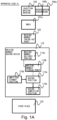
Figure 1A is a view illustrating a configuration of a control system of anEmbodiment 1. -
Figure 1B is a view illustrating the configuration of the control system of theEmbodiment 1. - Part (a) of
Figure 2 is a view illustrating an injection molding machine of theEmbodiment 1 and part (b) ofFigure 2 is a view illustrating an operating screen of the injection molding machine. -
Figure 3 is a view illustrating a process until a molding member of theEmbodiment 1 is packed. - Part (a) of
Figure 4 is a view illustrating a partition and a mark on a lid of a returnable box of theEmbodiment 1, and part (b) ofFigure 4 is a view illustrating other marks. - Part (a) of
Figure 5 is a view illustrating a movement to a packing completion position of the returnable box of theEmbodiment 1, part (b) ofFigure 5 is a view illustrating an image processing screen, and part (c) ofFigure 5 is a view illustrating a database at the packing completion position. -
Figure 6 is a flowchart illustrating a registration process to the database of theEmbodiment 1. - Part (a) of
Figure 7 is a view illustrating a state of an inventory storage area of theEmbodiment 1, and part (b) ofFigure 7 is a view illustrating the database in the state of part (a). - Part (a) of
Figure 8 is a view illustrating the image processing screen of theEmbodiment 1 and part (b) ofFigure 8 is a view illustrating a virtual inventory storage area of a display unit. - Part (a) of
Figure 9 is a view illustrating the database of theEmbodiment 1 at 13:00 and part (b) ofFigure 9 is a view illustrating the database of theEmbodiment 1 at 13:20. - Part (a) of
Figure 10 is a view illustrating the virtual inventory storage area of the display unit of theEmbodiment 1 and part (b) ofFigure 10 is a view illustrating the image processing screen. - Part (a) of
Figure 11 is a view illustrating the inventory storage area of theEmbodiment 1, and part (b) ofFigure 11 is a view illustrating the virtual inventory storage area of the display unit in the state of part (a). - Part (a) and part (b) of
Figure 12 are views illustrating the database of theEmbodiment 1 in the state of part (b) ofFigure 11 . -
Figure 13 is a view illustrating the inventory storage area and the virtual inventory storage area of the display unit of theEmbodiment 1. -
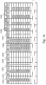
Figure 14 is a view illustrating the database shared with a device controlling a free feeding trolley of theEmbodiment 1, etc. - Part (a) of
Figure 15 is a view illustrating coordinates shared with the device controlling the free feeding trolley of theEmbodiment 1, etc., and part (b) ofFigure 15 is a view illustrating the database in the state of part (a). - Part (a) of
Figure 16 is a view illustrating the inventory storage area of theEmbodiment 1 and part (b) ofFigure 16 is a view illustrating a backup of the database. - Part (a) of
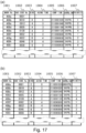
Figure 17 is a view illustrating the database of theEmbodiment 1 when the returnable box becomes empty and part (b) ofFigure 17 is a view illustrating the database of theEmbodiment 1 when a new molding member is stored in the returnable box. - Part (a) of
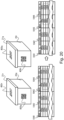
Figure 18 is a view illustrating an empty box standby position of theEmbodiment 1 and part (b) ofFigure 18 is a view illustrating a state in which the mark is attached to both the returnable box and the lid thereof and the database thereof. -
Figure 19A is a view illustrating a plurality of the returnable boxes of theEmbodiment 1 with the mark being attached to the returnable box and the lid thereof and the database thereof. -
Figure 19B is a view illustrating a state in which the returnable boxes of theEmbodiment 1 are stacked and the database thereof. -
Figure 20 is a view illustrating a state in which lids of theEmbodiment 1 are swapped and the database thereof. - Part (a) of
Figure 21 is a view illustrating a state in which the mark is attached to a mold of theEmbodiment 1, and part (b) is a view illustrating the database thereof. -
Figure 22A is a view illustrating a system configuration of a modified example of theEmbodiment 1. -
Figure 22B is a view illustrating the system configuration of the modified example of theEmbodiment 1. -
Figure 22C is a view illustrating the system configuration of the modified example of theEmbodiment 1. -
Figure 23 is a view illustrating a configuration of the control system of anEmbodiment 2. - Part (a) of
Figure 24 is a view illustrating a reading by a mark reading portion of theEmbodiment 2, part (b) ofFigure 24 is a view illustrating an image processing screen of theEmbodiment 2, and part (c) ofFigure 24 is a view illustrating a modified example of information indicating the kind of theEmbodiment 2. - Part (a) of
Figure 25 is a view illustrating a database of theEmbodiment 2, and part (b) ofFigure 25 is a view illustrating an inventory storage area of theEmbodiment 2. -
Figure 26 is a flowchart illustrating a registration process to the database of theEmbodiment 2. -
Figure 27 is a view illustrating a configuration of the control system of anEmbodiment 3. - Part (a) of
Figure 28 is a view illustrating a process of theEmbodiment 3 until a molding member is packed, and part (b) ofFigure 28 is a view illustrating a state in which the molding members are stored. -
Figure 29A is a view illustrating a database of theEmbodiment 3. -
Figure 29B is a view illustrating the database of theEmbodiment 3. - Part (a) of
Figure 30 is a view illustrating a database of a modified example of theEmbodiment 3 and part (b) ofFigure 30 is a view illustrating a position for replenishing the resin material. - Part (a) and part (b) of
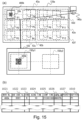
Figure 31 are views illustrating a plurality of returnable boxes in the modified example of theEmbodiment 3. - Hereinafter, Embodiments which are examples for practicing the present invention will be described with referring to the attached drawings. Configurations shown below is only examples, and details, for example, may be changed by those skilled in the art to the extent not to depart from the intent of the present invention. In addition, figures taken up in the present Embodiments are for reference only and do not limit the present invention.
- A system configuration of a control system for controlling a molding member of an
Embodiment 1 is illustrated inFigure 1A andFigure 1B . In theEmbodiment 1, the system configuration will be described largely divided into a device side S1 and a system side S2. As shown inFigure 1A , the device side S1 is constituted by aninjection molding machine 100, amold 101a, a robot for taking out themolding member 102, a device for packing themolding member 110 and aninventory storage area 120. Theinjection molding machine 100, which molds the molding member, includes anoperating panel 100a and anoperating screen 100b. The device for packing themolding member 110 includes a portion for handing over themolding member 110a and a robot for storing themolding member 110b. As a first place, where a returnable box is placed and related to the device for packing themolding member 110, there are provided apacking position 110c, apacking completion position 110d, an emptybox standby position 110e, etc. - In addition, the system side S2 is constituted by a
record controlling portion 130, amark reading portion 140, animage analyzing portion 150, aserver 300, and adisplay unit 310. As a position related to the system side S2, there are provided a position for reading and picking up akind 40a, a position for reading and picking up afinished product 40b, a position for reading and picking up theinventory storage area 40c, etc. - In the
Embodiment 1, it will be described with the molding member, which is molded by theinjection molding machine 100 on thedevice side S 1, being taken as an example. In addition, a general programmable controller (hereinafter abbreviated as PLC) is used as therecord controlling portion 130, which performs an association of various information on the molding member. In addition, themark reading portion 140, which is a first pickup means, shall be a camera connected to a network (hereinafter abbreviated as NWC). It is configured that an image picked up by themark reading portion 140 is analyzed by theimage analyzing portion 150, which is connected via a network, such as a LAN, for example. - Incidentally, in the
Embodiment 1, as theinjection molding machine 100, for example, a fully automatic injection molding machine SE-HSZ from Sumitomo Heavy Industries, Ltd. is used, and as therecord controlling portion 130, MELSEC-Q series from Mitsubishi Heavy Industries, Ltd. is used. Furthermore, as themark reading portion 140, VB-H45 from Canon Inc., which is the NWC capable of pan, tilt and zoom, is used. In addition, as theimage analyzing portion 150, Canon Industrial Imaging Platform (hereinafter abbreviated as CIIP) Vision Edition (hereinafter abbreviated as VE) from Canon Inc. is used. This CIIP VE has functions to analyze an image picked up by the NWC and to read a bar code. - In addition, the
mark reading portion 140 used in theEmbodiment 1 can also be mounted on a ceiling in general. Thus, it becomes possible to minimize an impact on a layout of existing devices and on human flow lines, and an additional human work. Incidentally, for each device described above, other products having similar functions may be used. For example, as themark reading portion 140, a bar code reader may be used, or a plurality of NWCs with fixed views may be set. Furthermore, a hand-held camera may be used. In addition, with respect to information on time and order of the molding member, which will be described below: - [1] The information on the time is defined by time associated with the molding member such as, mold opening/closing time when the molding member is molded, starting or completion time of process time related to the molding such as injection and dwelling time, molding completion time and taking-out time, time when the molding member is stored in the returnable box, starting or completion time of packing of the molding member to the returnable box, time when the returnable box reaches and is placed in the inventory storage area, aging time determined by molded date and time and the molding member, and time when a work ID for storing the information on the molding member to the database is generated.
- [2] The information on the order is defined by a shot number of the molding member (order of molding), order of packing the molding member to the returnable box, order of completion of packing of the molding member, etc. For example, in a case in which only [1] the time information is provided, if the completion time of packing of the molding member is defined as year, month, date, hour, minute and second, then the order of molding of the stored molding member can be specified based only on the time information.
- Next, in a case in which [1] the time information + [2] the order information are provided, if the completion time of packing of the molding member has only year, month and date (in cases in which the aging time is short, qualitative, or the like), it is difficult to specify the order of molding based only on the time information, therefore, by acquiring the information on the shot number of the molding member, it becomes possible to specify the order of molding.
- And in a case in which only the order information is provided, if the aging time is short and the molding member is used up in one day (e.g., in a process where the molding member can be consumed in a downstream process immediately after molding), data may include only the shot number of the molding member or the order of completion of packing. In addition, there is nothing wrong with further combining the information on the time and the information on the order.
- Part (a) of
Figure 2 is a view illustrating theinjection molding machine 100 of theEmbodiment 1, and is a schematic view of a state before themolding member 10 is molded and taken out. As shown in part (a) ofFigure 2 , a case in which themold 101a is set in theinjection molding machine 100 to mold themolding member 10 will be described in detail. Theinjection molding machine 100 molds the molding members of the same shape while using acertain mold 101a. An operator operates theoperating panel 100a of theinjection molding machine 100 and inputs a molding condition for molding themolding member 10, or calls up the molding condition saved in advance. The molding condition of themolding member 10 input or called up are then displayed on theoperating screen 100b. After the display of the molding condition on theoperating screen 100b, the operator starts a molding operation of theinjection molding machine 100. Theinjection molding machine 100 injects molten molding material into the clampedmold 101a and molds themolding member 10 based on the input or called molding condition. As the molding condition, various known parameters such as temperature, pressure, time, amount, speed, position, etc. are included. Themolding member 10 molded by theinjection molding machine 100 is then taken out from themold 101a by the robot for taking out themolding member 102 after themold 101a is opened. - As shown in
Figure 1A andFigure 1B , themark reading portion 140 is fixedly or movably set in a position from which themark reading portion 140 can pick up theoperating screen 100b. Incidentally, in a case in which themark reading portion 140 is movably set, the position for reading and picking up thekind 40a is registered in a storage portion (not shown) in advance, and themark reading portion 140 shall move to the position for reading and picking up thekind 40a, which is read out from the storage portion. In addition, in a case in which themark reading portions 140 are fixedly set, at least onemark reading portion 140 should be set at each of a plurality of pickup positions described below. In other words, a second image pickup means, different from the first image pickup means, may be provided. Furthermore, onemark reading portion 140 may have a field of view which allows themark reading portion 140 to pick up the plurality of pickup positions. In the case in which themark reading portion 140 is movably set, it may be configured that onemark reading portion 140 shall move to the plurality of pickup positions, or a plurality ofmark reading portions 140 shall move to pick up positions within a certain defined range. With respect to the configuration of the set of themark reading portion 140, various combinations may be applied. - The
mark reading portion 140 picks up theoperating screen 100b at the position for reading and picking up thekind 40a. The image picked up by themark reading portion 140 is transmitted to theimage analyzing portion 150. Part (b) ofFigure 2 is a view illustrating animage processing screen 150a of theimage analyzing portion 150, and is a schematic view illustrating an image processing which analyzes information on the kind (hereinafter referred to as "kind information") from the picked up operatingscreen 100b of theinjection molding machine 100. As shown in part (b) ofFigure 2 , theoperating screen 100b is displayed on theimage processing screen 150a of theimage analyzing portion 150. Theimage analyzing portion 150 can then identify the current kind of the molding member by capturing amolding condition name 11 within animage processing area 150b and performing the image processing. Incidentally, it is necessary for a program of the image processing to be constructed and registered in advance in a storage portion (not shown), which is provided to theimage analyzing portion 150, so that the kind information of themolding member 10 can be read from themolding condition name 11. - In the
Embodiment 1, a rule is defined that a name of the kind of the molding member 10 (hereinafter referred to as "kind name") should be disposed at a right end of themolding condition name 11, and a program for reading a character at the right end of theimage processing area 150b is developed. By this, theimage analyzing portion 150 performs the image processing of an image within theimage processing area 150b and determines the kind of themolding member 10 to be, for example, "A". Incidentally, a location for identifying the kind is not limited to the location of themolding condition name 11, but may be positions of other information displayed on theoperating screen 100b, such as a molding temperature 12 (°C),molding condition 13, etc. Theoperating screen 100b, which is provided to theinjection molding machine 100, serves as a first display portion for displaying information on at least the kind of the molding member. -
Figure 3 is a view illustrating a process before themolding member 10 is packed, and is a schematic view illustrating a state in which themolding member 10 is transferred from the portion for handing over themolding member 110a to thepacking position 110c. Themolding member 10 is placed in the portion for handing over themolding member 110a of the device for packing themolding member 110 after being taken out from theinjection molding machine 100 by the robot for taking out themolding member 102, as shown by an arrow of broken line inFigure 3 . The robot for storing themolding member 110b takes out themolding member 10 from the portion for handing over themolding member 110a. The robot for storing themolding member 110b' sequentially stores the molding members 10' in areturnable box 20a (box), which is set at thepacking position 110c. Incidentally, in a case in which themolding member 10 can be packed in a posture as it is taken out, or in a case in which a process such as inspection is not performed on themolding member 10 immediately after it is taken out, the robot for taking out themolding member 102 may also serve as the robot for storing themolding member 110b. - Part (a) of
Figure 4 is a schematic view illustrating apartition 23a of thereturnable box 20a and amark 400a on alid 21a. As shown in part (a) ofFigure 4 , thereturnable box 20a is provided with thepartition 23a so that themolding members 10 can be stored in an aligned manner. In addition, thereturnable box 20a is made of plastic in terms of conveyance, rigidity, etc., and a plurality ofreturnable boxes 20a of the same shape are used to store a large quantity of themolding members 10. Incidentally, thereturnable box 20a does not have to be provided with thepartition 23a, nor does it have to be made of plastic. To thelid 21a, themark 400a is attached, which is a first mark indicating information on the box for identifying eachreturnable box 20a. In theEmbodiment 1, thereturnable box 20a is provided with thepartition 23a to store, for example, the sixteenmolding members 10 inside. - The molding/storing of the
molding member 10 is repeated in this manner, and when thereturnable box 20a becomes full, thelid 21a is put on an opening of thereturnable box 20a. Thelid 21a includes themark 400a as shown in part (a) ofFigure 4 and is configured to be separate from thereturnable box 20a, however, thelid 21a may be configured to be integral with thereturnable box 20a. Here, part (b) ofFigure 4 is a schematic view illustrating other marks, i.e., modified examples of the first mark. In theEmbodiment 1, as themark 400a, for example, a two-dimensional code is used, however, as shown in part (b) ofFigure 4 , a one-dimensional bar code, a symbol or a number, each of which can be identified, Data Matrix, which is another two-dimensional code, etc., may be used as long as each of these can be identified. Thus, the first mark (mark 400a) may include a character, a graphic, a symbol, a color, a one-dimensional bar code or a two-dimensional code, or a combination thereof. - Part (a) of
Figure 5 is a schematic view illustrating a state in which thereturnable box 20a is transported to thepacking completion position 110d. As shown in part (a) ofFigure 5 , thereturnable box 20a is transported from thepacking position 110c to thepacking completion position 110d by a moving means such as a conveyor belt, for example. - As shown in
Figure 1A ,Figure 1B and part (a) ofFigure 5 , themark reading portion 140 is fixedly or movably set at the position for reading and picking up thefinished product 40b, which is a position where themark 400a, which is attached to thelid 21a of thereturnable box 20a placed at thepacking completion position 110d, can be picked up. Incidentally, in the case in which themark reading portion 140 is movably set, the position for reading and picking up thefinished product 40b shall be registered in the storage portion (not shown) in advance. - The picked-up image is transmitted to the
image analyzing portion 150. Part (b) ofFigure 5 is a view illustrating theimage processing screen 150a of theimage analyzing portion 150, and is a schematic view illustrating a state of the image processing which reads themark 400a. As shown in part (b) ofFigure 5 , themark 400a is displayed on theimage processing screen 150a of theimage analyzing portion 150. Theimage analyzing portion 150 then captures themark 400a in theimage processing area 150c, recognizes themark 400a by the image processing, and transmits information that themolding member 10 is stored in thereturnable box 20a to which themark 400a is attached to therecord controlling portion 130, and therecord controlling portion 130 records the information. Theimage analyzing portion 150 functions as an acquiring means for analyzing the image of themark 400a of thereturnable box 20a picked up by themark reading portion 140 and acquiring the information on the box. Then, therecord controlling portion 130 refers to a timer (not shown) and defines time when themark 400a is picked up as completion time of packing, so that the time when themark 400a is picked up can be used as completion time of packing Ta of themolding member 10. Incidentally, as in the kind reading, definitions, etc. of the information on the time and the order of the molding member should be programmed in advance. In theEmbodiment 1, it is defined as the completion time of packing. Therecord controlling portion 130 functions as a construction means for constructing a database by associating the information on the box acquired by theimage analyzing portion 150 with the information on the time and the order of the molding member. -
Figure 6 is a flowchart illustrating a registration process to the database. In the flowchart ofFigure 6 , which illustrates a process for associating the returnable box, the kind of the molding member and the completion time of packing by the system side S2, when the molding of themolding member 10 by theinjection molding machine 100 starts, processes after a step 101 (hereinafter referred to as S 101) is initiated. Incidentally, hereinafter the description will be made under an assumption that themark reading portion 140 is set in the movable configuration. In S101, the system side S2 moves themark reading portion 140 to the position for reading and picking up thekind 40a. - In S102, the system side S2 picks up the
operating screen 100b of theinjection molding machine 100 by themark reading portion 140 and determines whether or not the kind information of themolding member 10 has been searched by theimage analyzing portion 150. Here, the search includes that theimage analyzing portion 150 captures the targetedmolding condition name 11 of part (b) ofFigure 2 , for example, within theimage processing area 150c. If the system side S2 determines in S102 that the search for the kind information is not completed, then returns the process to S102 to continue the search, and if the system side S2 determines that the search is completed, then proceeds the process to S103. - In S103, the system side S2 acquires the kind information by the image processing of the
image analyzing portion 150. As described above, the image picked up by themark reading portion 140 is transmitted to theimage analyzing portion 150, and theoperating screen 100b is displayed on theimage processing screen 150a of theimage analyzing portion 150, as shown in part (b) ofFigure 2 . Here, on theoperating screen 100b, for example, the input or called up name of molding condition (themolding condition name 11 described above) and specific conditions, such as molding temperature (°C) 12 andother molding conditions 13 are displayed together with themolding condition name 11. - In S104, the system side S2 moves the
mark reading portion 140 to the position for reading and picking up thefinished product 40b. Incidentally, the system side S2 may move themark reading portion 140 in advance to the position for reading and picking up thefinished product 40b without waiting for thereturnable box 20a to be transported to thepacking completion position 110d. In S105, the system side S2 picks up themark 400a of thereturnable box 20a by themark reading portion 140 and determines whether or not a search for themark 400a by theimage analyzing portion 150 is completed. Here, the search includes that theimage analyzing portion 150 captures the targetedmark 400a within theimage processing area 150c. Incidentally, in S104, the system side S2 stores the time when themark 400a is picked up by themark reading portion 140 by therecord controlling portion 130 in the storage portion (not shown) as the completion time of packing Ta. If the system side S2 determines in S105 that the search for themark 400a is not completed, then returns the process to S105, and if the system side S2 determines that the search for themark 400a is completed, then proceeds the process to S106. - In S106, the system side S2 acquires information of the
mark 400a searched in S 105 and the completion time of packing Ta stored in the storage portion (not shown). In S107, the system side S2 registers themark 400a of thereturnable box 20a to the database by therecord controlling portion 130. In S108, the system side S2 associates themark 400a of thereturnable box 20a registered in the database with the kind information acquired in S 103 and the completion time of packing Ta acquired in S 106, registers these to the database, and ends the process. - As described in the flowchart of
Figure 6 , the various data collected by theimage analyzing portion 150 is transmitted to therecord controlling portion 130, which is connected via the LAN, association of the information is performed by therecord controlling portion 130, and the database is constructed. - Part (c) of
Figure 5 is a view illustrating an example of the database at thepacking completion position 110d. The data transmitted to therecord controlling portion 130 are associated with each other in a database structure shown in part (c) ofFigure 5 . As shown in part (c) ofFigure 5 , in the database of theEmbodiment 1, one record is registered permark number 1001. Each record has columns such as a bar code No. 1002, akind 1003, an agingtime 1004, acompletion time 1005, ashipping availability 1006, and apriority order 1007, which are associated as attributes. In theEmbodiment 1, for the sake of simplicity of description, the reference numeral "400a" of themark 400a is used for themark number 1001. However, in practice, it may be configured that a serial number starting from 0 or any number is used, or that the bar code No. 1002 also serve as themark number 1001, etc. The bar code No. 1002 is an unordered number indicating themark 400a. - In the
Embodiment 1, in a recording position of themark number 1001 being "400a", "0001", which is the bar code No. indicated by themark 400a, is stored in the bar code No. 1002. In addition, "A", which indicates the kind of themolding member 10, is stored in thekind 1003, and the completion time of packing Ta is registered (recorded) in thecompletion time 1005, respectively. Then an aging time T corresponding to the kind of the molding member 10 (e.g., "A", etc.) is then recorded in the agingtime 1004. In theEmbodiment 1, thecompletion time 1005 of the mark number "400a" shall be "2110091000", and the aging time T of the kind "A" of themolding member 10 shall be 3 hours. The completion time is represented as a series of numbers: year (last two digits thereof), month, date, hour and minute. For example, in the database of part (c) ofFigure 5 , the completion time of packing Ta, which can be read from the information registered in a field of thecompletion time 1005 of themark 400a, is "October 9, 2021, 10:00". Incidentally, a format in which the data is registered may be changed depending on the data handled in thecompletion time 1005. In addition, the aging time T may vary depending on the kind of themolding member 10. At a stage when the data is registered, since the specified aging time T has not yet elapsed, or in other words, counting of the aging time has just started, "shipping unavailable" is registered in theshipping availability 1006. After the database construction is completed as described above, the database is stored in theserver 300, which is connected via the LAN, etc. as appropriate. Incidentally, therecord controlling portion 130 may start counting of time by the timer (not shown) to control the aging time T at a timing of completion of the registration of the database on thereturnable box 20a. - As described above, when the
molding member 10 is stored in thereturnable box 20a and the database construction of the information such as themark 400a, the kind, and completion time of packing Ta is completed, a completion notification is notified to a worker X. The completion notification to the worker X is performed via thedisplay unit 310, which is connected to therecord controlling portion 130 via a network means such as the LAN or RS232C. Upon receiving the completion notification, the worker X feeds thereturnable box 20a from thepacking completion position 110d to any location in theinventory storage area 120. - By repeating the above processes and operations (
process 1 through process 6), thereturnable boxes 20a storing themolding members 10 molded by theinjection molding machine 100 will be placed one after another in theinventory storage area 120. Part (a) ofFigure 7 is a schematic view illustrating a state when nine boxes of thereturnable boxes 20a through 20i are placed in theinventory storage area 120. In theEmbodiment 1, nine boxes of thereturnable boxes 20a through 20i are placed in theinventory storage area 120, as shown in part (a) ofFigure 7 . Incidentally, the marks corresponding to thereturnable boxes 20a through 21i will be themarks 400a through 400i attached to thelids 21a through 21i. In addition, thereturnable boxes 20f through 20i store the molding members of the kind B, which are molded on the same day by theinjection molding machine 100 and with which the information is associated through the same processes and operation (process 1 through process 6) as the kind A described above. Incidentally, an even greater number of returnable boxes may be placed, or even a greater number of kinds may be mixed. Hereinafter, suffixes of reference numeral a, b..., etc. may be omitted except when describing a specific returnable box, etc. - Part (b) of
Figure 7 is a view illustrating the database corresponding to the state of part (a) ofFigure 7 , i.e., the database corresponding to thereturnable boxes 20a through 20i placed in theinventory storage area 120 in part (a) ofFigure 7 . Various information registered in the records of each mark (in other words, the returnable box) registered to themark number 1001 is stored. For example, with respect to thereturnable box 20d, information such as following is associated with the record of themark number 1001 being "400d" and constructed as the database. That is, the bar code No. 1002 is "0005", thekind 1003 is "A", the agingtime 1004 is "3" hours, thecompletion time 1005 is "2110091100", and theshipping availability 1006 is "shipping unavailable". In addition, for example, with respect to thereturnable box 20g, information such as following is associated with the record of themark number 1001 being "400g" and constructed as the database. That is, the bar code No. 1002 is "0032", thekind 1003 is "B", the agingtime 1004 is "4" hours, thecompletion time 1005 is "2110090830", and theshipping availability 1006 is "shipping unavailable". - As shown in
Figure 1A andFigure 1B , themark reading portion 140 is moved to the position for reading and picking up theinventory storage area 40c, which is a position where themark reading portion 140 can pick up themarks 400a through 400i attached to thelids 21a through 20i of thereturnable boxes 20a through 20i placed in theinventory storage area 120. The position for reading and picking up theinventory storage area 40c is registered in advance. Incidentally, themark reading portion 140 may be fixedly set. The image picked up by themark reading portion 140 is transmitted to theimage analyzing portion 150. Part (a) ofFigure 8 is a view illustrating theimage processing screen 150a of theimage analyzing portion 150, and is a schematic view illustrating a state of the image processing which reads the picked-upmarks 400a through 400i. As shown in part (a) ofFigure 8 , themarks 400a through 400i are displayed on theimage processing screen 150a of theimage analyzing portion 150, and theimage analyzing portion 150 acquires the coordinates of themarks 400a through 400i in the image processing. Specifically, theimage analyzing portion 150 finds themarks 400a through 400i within a range of animage processing area 150d. Incidentally, in theimage processing area 150d, a position indicating an origin of X and Y coordinates is assumed in advance, and theimage analyzing portion 150 shall determine the coordinates of themarks 400a through 400i based on the origin. In addition, in theEmbodiment 1, two-dimensional coordinates as the coordinates indicating the position of the mark is used, however, three-dimensional coordinates may be used by adding a coordinate in a height direction (Z coordinate) in a case, for example, in which the returnable boxes are placed in a stacked manner, etc. In addition, in theEmbodiment 1, a rectangular coordinate system is used, however, other coordinate systems, such as a polar coordinate system, may be used. - From the found
marks 400a through 400i, theimage analyzing portion 150 acquires positional information X1 through X9 and Y1 through Y9 of themarks 400a through 400i (hereinafter referred to as positional information of the mark) in an angle of view of themark reading portion 140. For example, for themark 400a of thereturnable box 20a, the positional information of the mark (X1, Y1) is acquired. Similarly, for themark 400b of thereturnable box 20b, the positional information of the mark (X2, Y2) is acquired, and up to the positional information (X9, Y9) for themark 400i of thereturnable box 20i is acquired. - Based on the positional information of the mark X1 through X9 and Y1 through Y9 acquired through the image processing by the
image analyzing portion 150, theimage analyzing portion 150 calculates positional information for displaying an image in a virtual space of thedisplay unit 310 using a conversion formula to a virtual coordinate system prepared in advance. Incidentally, the positional information for displaying the image in the virtual space of the display unit (virtual coordinates) is hereinafter referred to as virtual positional information for display and is denoted by XX1 through XX9 and YY1 through YY9. - Here, virtual representation of the
inventory storage area 120 on thedisplay unit 310 is referred to as a virtualinventory storage area 220. Part (b) ofFigure 8 is a schematic view illustrating the virtualinventory storage area 220 displayed on thedisplay unit 310, which is a second display portion. As shown in part (b) ofFigure 8 ,information 410a through 410i corresponding to themark 400 of eachbox 20 is disposed in the virtualinventory storage area 220 displayed on thedisplay unit 310, based on the virtual positional information for display XX1 through XX9 and YY1 through YY9. Thus, theinformation 410a is an image virtually indicating themark 400a. In addition, in theEmbodiment 1, kind information 51a through 51i is displayed at the positions of theinformation 410a through 410i so that the worker can determine which position of thereturnable box 20 in theinventory storage area 120 stores which kind of themolding member 10 just by looking at thedisplay unit 310. - Thus, by identifying the
marks 400a through 400i of thereturnable boxes 20a through 20i placed in theinventory storage area 120 with theimage analyzing portion 150, the actualinventory storage area 120 shown in part (a) ofFigure 7 can be virtually displayed (virtual view can be displayed) on thedisplay unit 310. Therefore, the worker X can easily know which kind of themolding member 10 is stored in whichreturnable box 20 simply by looking at thedisplay unit 310. - In addition, the
mark reading portion 140, which has been moved to or fixed up at the position for reading and picking up theinventory storage area 40c, picks up theinventory storage area 120 at predetermined time interval (e.g., several 10 seconds, etc.). By this, it becomes possible to respond in a case in which changes occur in thereturnable boxes 20 in theinventory storage area 120, such as when thenew returnable box 20 is placed in theinventory storage area 120 or when the returnable box is moved manually, etc. In other words, by themark reading portion 140 picking up theinventory storage area 120 at the predetermined time intervals, it becomes possible to detect changes in condition of theinventory storage area 120 and to update information on the condition of theinventory storage area 120. As described above, it is configured that themark reading portion 140 picks up theinventory storage area 120 at a certain time interval at the position for reading and picking up theinventory storage area 40c. - Part (a) of
Figure 9 is a view illustrating changes in the database at 13:00, i.e., when the aging time for the kind A has elapsed (hereinafter referred also to as an end of the aging). More in detail, it is the database in a state in which three hours have elapsed after the storing to thereturnable box 20a is completed, i.e., after the information on thereturnable box 20a is registered to the database, i.e., the time is 13:00. The agingtime 1004 is three hours since themolding member 10 stored in thereturnable box 20a is kind A. Therefore, therecord controlling portion 130 changes theshipping availability 1006, which is associated with the record of themark 400a, from "shipping unavailable" to "shipping available" because three hours have elapsed. - In the
Embodiment 1, therecord controlling portion 130 starts counting elapsed time with the timer (not shown) as well as records the time in thecompletion time 1005. In therecord controlling portion 130, a program, which writes "shipping available" to the database after therecord controlling portion 130 determines that the aging time for the kind has elapsed, is embedded. In addition, therecord controlling portion 130 also determines whether or not there is any other kind A of which theshipping availability 1006 is "shipping available" in the database. In part (a) ofFigure 9 , thepriority order 1007 becomes "1" in the record of themark number 1001 being "400a" since there is noother mark number 1001 of which theshipping availability 1006 is "shipping available" among the kind A. As such, therecord controlling portion 130 determines the priority order for shipping of the returnable boxes based on the information on the kind and the completion time. - Incidentally, in part (a) of
Figure 9 , for the kind B of themark number 1001 being "400f" and "400g", four hours have already elapsed from thecompletion time 1005 and the information "shipping available" is registered for both of theshipping availability 1006. In addition, the information "1" and "2" are also registered in thepriority order 1007, respectively. For the kind B of themark number 1001 being "400h", because four hours has elapsed from thecompletion time 1005 thereof at the timing of part (a) ofFigure 9 , the information is updated with "shipping available" in theshipping availability 1006 and "3" in thepriority order 1007, as described above for themark number 1001 being "400a". For thereturnable box 20h, thepriority order 1007 is set to "3" since the priority orders "1" and "2" have already been registered. - Part (b) of
Figure 9 is a view illustrating changes in the database at 13:20, i.e., at the end of the aging time, and it is the database of a state in which three hours and twenty minutes has elapsed after the storing to thereturnable box 20a is completed. Since themolding member 10 stored in thereturnable box 20b is kind A and three hours have elapsed since the completion, theshipping availability 1006 associated with themark 400b indicating thereturnable box 20b is changed to "shipping available". And since there is data for the kind A which has already been "shipping available", thepriority order 1007 for thereturnable box 20b becomes "2". By determining the priority order in this manner, it becomes possible to ship in order from what has earlier time stored in thecompletion time 1005. In addition, since the same processes are applied to themarks 400f through 400i associated with thereturnable boxes 20f through 20i, status of the shipment availability and the priority order changes in the same manner. - A case in which two more hours have elapsed from the state shown in part (b) of
Figure 9 , i.e., a feeding order for themolding member 10 of kind A is issued at 15:20 will be illustrated using part (a) ofFigure 10 . Part (a) ofFigure 10 is a view illustrating the virtualinventory storage area 220 on thedisplay unit 310, and a schematic view of a case in which an area corresponding to thereturnable box 20a, to which the feeding order is issued, is displayed so as to be standing out in particular. Incidentally, with respect to part (a) ofFigure 10 , the same reference numeral is used for the same configuration as part (b) ofFigure 8 . In theEmbodiment 1, based on theinformation 410a through 410i on thedisplay unit 310, therecord controlling portion 130 automatically identifies (extracts) themark number 1001, in which themolding member 10 of kind A is stored, of which theshipping availability 1006 is "shipping available", and of which thepriority order 1007 is "1". Therecord controlling portion 130 refers to the database at the time of receiving the feeding order and extracts themark 400a of thereturnable box 20a, for example, in a case of the state such as part (b) ofFigure 9 . As shown in part (a) ofFigure 10 , therecord controlling portion 130 displays theinformation 410a, which indicates themark 400a of thereturnable box 20a, in a manner to be distinguishable from theother marks 400b through 400i, such as highlighting, etc. (in part (a) ofFigure 10 , shown in hatching). As such, by using thedisplay unit 310, it becomes possible to inform the worker X of thereturnable box 20a to be fed by using visual information. Incidentally, with respect to a way of the display so as to be distinguishable, the returnable box to be fed may be informed by other different means. - Then, in order to find the
returnable box 20a to be fed, the worker X will use coordinates information on thedisplay unit 310, the two-dimensional code reader, etc. to find thereturnable box 20a in the actualinventory storage area 120. Here, part (b) ofFigure 10 is a view illustrating animage analyzing screen 150a of theimage analyzing portion 150, and is a schematic view when a symbol for human visibility (30a) is attached along with themark 400a. Incidentally, the same reference numeral is attached to the same configuration as in part (b) ofFigure 5 . A fourth mark, which is thehuman visibility mark 30a, indicating the information on the returnable box in a recognizable state by a human may be attached adjacent to themark 400a, which is the first mark. In theEmbodiment 1, as shown in part (b) ofFigure 10 , therecord controlling portion 130 displays "0001" of the bar code No. 1002, which is indicated by themark 400a, as a mark which can be understood by the worker X adjacent to themark 400a. By this, it becomes easy even for a human eye to locate thereturnable box 20a. The identifiedreturnable box 20a is fed to the downstream process. - In part (a) of
Figure 11 , a state of theinventory storage area 120 after thereturnable box 20a is fed to a downstream process is illustrated. In part (a) ofFigure 11 , the same reference numeral is attached for the same configuration as in part (a) ofFigure 7 . As described in theprocess 7, themark reading portion 140 picks up theinventory storage area 120 at the predetermined time intervals. By this, as shown in part (a) ofFigure 8 , by performing the image processing, the state of the inventory storage are 120 is updated. In other words, theimage analyzing portion 150 cannot find themark 400a in the image processing since themark 400a is not present. Thus, theimage analyzing portion 150 also determines presence or absence of themark 400 as a result of the image analysis on the picked-up image of theinventory storage area 120. If theimage analyzing portion 150 cannot find themark 400a, thenimage analyzing portion 150 erases theinformation 410a indicating themark 400a from theimage processing screen 150a. Part (b) ofFigure 11 is a schematic view illustrating the virtualinventory storage area 220 displayed on thedisplay unit 310 corresponding to the state in part (a) ofFigure 11 . Therecord controlling portion 130 updates the display of thedisplay unit 310 as shown in part (b) ofFigure 11 . Furthermore,Figure 12 is the database showing a state of part (b) ofFigure 11 . Therecord controlling portion 130 updates the information in the database as shown in part (a) ofFigure 12 . - Specifically, the
record controlling portion 130 updates the record of which themark number 1001 is "400a". That is, for the record of themark number 1001 being "400a", theshipping availability 1006 is changed to "shipped" and thepriority order 1007 is updated to blank. Accordingly, the priority order for other molding members of the same kind will be updated. For example, the record of themark number 1001 being "400b" is updated, and thepriority order 1007 is updated from "2" to "1". In addition, as another way to update the database, therecord controlling portion 130 may monitor the status of theshipping availability 1006 at predetermined time intervals and perform updating of the priority order. - Furthermore, in the
Embodiment 1, after theprocess 6, the worker X feeds thereturnable box 20 to arbitrary position in theinventory storage area 120, however, it is not limited to this configuration. The returnable box may be fed to a predetermined position. In addition, the returnable boxes may be fed using an automatic guided vehicle (AGV) or the free feeding trolley. - In a case in which the feeding of returnable boxes is performed by using a feeding device such as the automatic guided vehicle (AGV) or the free feeding trolley, since people may enter the
inventory storage area 120, the free feeding trolley of human-cooperating type is preferable. Furthermore, there is a case in which people may take the returnable box out for sampling inspection, etc., and not return the returnable box to the same position. For example, a case in which thereturnable box 20h is moved from the state of part (a) ofFigure 11 to the position where thereturnable box 20a was placed will be described.Figure 13 is a schematic view of theinventory storage area 120 when thereturnable box 20h is moved and a schematic view of the virtualinventory storage area 220 displayed on thedisplay unit 310. Even if thereturnable box 20h is moved to the position where thereturnable box 20a was placed, since themark reading portion 140 picks up theinventory storage area 120 at the predetermined time intervals, the image of the virtualinventory storage area 220 on thedisplay unit 310 is also updated based on the newly picked up image, as shown inFigure 13 . By this, even if the position of thereturnable box 20h is changed, the operator X will know the changed position. - In addition, in the case using the device such as the automatic guided vehicle (AGV) and the free feeding trolley, it is preferable to configure as following.
Figure 14 is a view illustrating the database shared with the device controlling the free feeding trolley, etc. For example, in a state ofFigure 13 , it is preferable to share the database with the device controlling the free feeding trolley, etc. so as to be able to know positions where thereturnable boxes 20b through 20i are placed, as shown inFigure 14. Figure 14 is the view illustrating the database in this case. The coordinates XX and YY of the virtual positional information fordisplay 1008 used for the display of thedisplay unit 310 constructed in theprocess 7 are shared by applying conversion formulas and converting to actual coordinates XXX1 through XXX9 and YYY1 through YYY9 of an actual coordinatesystem 1009, which is shared with the device controlling the free feeding trolley, etc. The actual coordinatesystem 1009 is a coordinate system, which is suitable for the automatic guided vehicle (AGV), the free feeding trolley, etc., to actually move around theinventory storage area 120, and in which a predetermined position is defined as an origin. In this manner, it becomes possible to specify an actual position of thereturnable box 20. Incidentally, since the image picked up by themark reading portion 140 is distorted in end portions, the coordinates may be corrected to take the distortion into account. For a method correcting the coordinates to account for the image distortion, known methods may be used. In the above, it may be configured that therecord controlling portion 130 associates the virtual coordinates with the information on the returnable boxes in the database, and the feeding device feeds the returnable boxes based on the database. - Part (a) of
Figure 15 is a schematic view illustrating coordinates which are shared with the device controlling the free feeding trolley, etc. In a case of a free location feeding, in which the positions for thereturnable boxes 20 to be placed are defined in advance, it may be configured as shown in part (a) ofFigure 15 . That is, in aninventory storage area 120a, placing positions P1 through P12 are lattice-likely arranged as the positions for the returnable boxes to be placed. Amark reading portion 140y then picks up images at pickup positions of themark reading portion 140y corresponding to the placing positions P1 through P12, and theimage analyzing portion 150 confirm presence or absence of themark 400 from the picked-up images. If themark 400 is present, then theimage analyzing portion 150 transmits information of themark 400 to therecord controlling portion 130, and therecord controlling portion 130 registers the information to the database. - Specifically, in the
inventory storage area 120a, the placing positions P1 through P12 for thereturnable boxes 20 to be placed are defined in advance. And a case in which, for example, thereturnable box 20k provided with themark 400k is placed at the placing position P1 will be described. Themark reading portion 140y is set so that the placing positions P1 and P4 are in itspickup range 43a. By performing the image processing on a picked-upimage 155, theimage analyzing portion 150 determines that themark 400k is present at the placing position P1 in an image processing area 150y1. On the other hand, theimage analyzing portion 150 determines that the mark is absent at the placing position P4 in the image processing area 150y2. - Thus, as shown in the database of part (b) of
Figure 15 , in aplacing position 1010 of themark number 1021 being "400k", "P1" indicating the placing position P1 is registered. Incidentally, part (b) ofFigure 15 is a view illustrating the database corresponding to the state of part (a) ofFigure 15 . In this manner, theinventory storage area 120a is picked up by themark reading portion 140y, which is changing the pickup positions one after another from thepickup range 43a through 43f. By this, it becomes possible to confirm (determine) whether the mark 400 (returnable box 20) is or is not present in theinventory storage area 120a. Incidentally, the database of part (b) ofFigure 15 is provided with columns for a bar code No. 1022 (e.g. "0001"), a kind 1023 (e.g. "K"), an aging time 1024 (e.g. "10") and a completion time 1025 (e.g. "2110091000"). In addition, the database is provided with columns for a shipping availability 1026 (e.g., "shipping unavailable") and apriority order 1027. - Furthermore, by configuring as the above process, it becomes not necessary to share detailed coordinate data. In addition, an actual coordinate system of the placing position P1 may be stored by the device controlling the free feeding trolley, etc. Needless to say, this configuration is also applicable for a case in which there are even more placing positions.
- After more time has elapsed from the state shown in
Figure 13 , a case in which thereturnable box 20a is fed to the downstream process, the moldingmember 10 is taken out in the downstream process, and thereturnable box 20a becomes empty and is returned to theinventory storage area 120 will be described. - The
mark reading portion 140 picks up theinventory storage area 120 at the predetermined time interval at the position for reading and picking up theinventory storage area 40c. Part (a) ofFigure 16 is a schematic view illustrating a status in which thereturnable box 20a, which became empty, is returned to theinventory storage area 120. As shown in part (a) ofFigure 16 , when thereturnable box 20a is returned to theinventory storage area 120, it can be recognized that themark 400a attached to thereturnable box 20a appears in theinventory storage area 120 by theimage analyzing portion 150 analyzing the image picked up by themark reading portion 140. Theimage analyzing portion 150 transmits this information to therecord controlling portion 130. - At this time, the
record controlling portion 130 can recognize, based on the database shown inFigure 12 , that thereturnable box 20a having themark 400a, whoseshipping availability 1006 is "shipped", is returned with becoming empty. Here, part (b) ofFigure 16 is a view illustrating another database for backup. As shown in part (b) ofFigure 16 , therecord controlling portion 130 may separately store the information as a backup in the storage portion (not shown) so that history of themark 400a can be followed in the database. For example, in the database for backup, an erasedtime 1035, etc., may be provided to record the time when thereturnable box 20a is returned with becoming empty to theinventory storage area 120, etc. Incidentally, a column for the erasedtime 1035 may be provided in the main database (the database which has been described). In theEmbodiment 1, in the database for backup, it is recorded that "400a" in a mark number 1031, "0001" in a bar code No. 1032, "A" in akind 1033, and "2110091000" in acompletion time 1034. As such, all information may be stored in the main database, or as shown in part (b) ofFigure 16 , a sub-database may be provided as the database for backup. In part (a) ofFigure 10 , assuming a case in which the shipping order is issued at, for example, 15:20 and the returnable box is returned, for example, three hours after the shipping, then "2110091820" is recorded in the erasedtime 1035 of the database. - Part (a) of
Figure 17 is a view illustrating the database in which the information in recording positions for themark 400a has been erased. As shown in part (a) ofFigure 17 , therecord controlling portion 130 deletes the information registered in the record positions for themark number 1001 being "400a", excluding information on the returnable box, for example, therecord controlling portion 130 deletes the information on themolding member 10, and leaves the information on thereturnable box 20a. Specifically, in the record of themark number 1001 being "400a", "400a" of themark number 1001 and "0001" of the bar code No. 1002 are kept. In the record of themark number 1001 being "400a", thekind 1003, the agingtime 1004, thecompletion time 1005, theshipping availability 1006, thepriority order 1007, etc. are deleted. - Then, after a new molding member is stored in the
empty returnable box 20a, information on the newly stored molding member is recorded in themark 400a. Part (b) ofFigure 17 is a view illustrating the database to which the new information is recorded in the record position for themark 400a. Part (b) ofFigure 17 represents the database when the new molding member (kind C) is molded by theinjection molding machine 100 and the molding member of the kind C is stored in thereturnable box 20a after theprocess 1 through theprocess 6. In the record corresponding to thereturnable box 20a, "C" for thekind 1003, "6" for the agingtime 1004, "2110091920" for thecompletion time 1005, "shipping available" for theshipping availability 1006, etc. are newly registered. Thus, it is possible to reuse not only thereturnable box 20a and themark 400a but the record in the database corresponding to thereturnable box 20a. - Part (a) of
Figure 18 is a schematic view when theempty returnable box 20a returns to the emptybox standby position 110e. Thereturnable box 20a which became empty and is returned may be returned directly to the emptybox standby position 110e, which stores the empty returnable boxes, for example, as shown in part (a) ofFigure 18 , rather than to theinventory storage area 120. At this time, the backup of the information in the record of the database and deletion of the information in the predetermined columns may be performed in theprocess 6. In addition, as shown in part (a) ofFigure 18 , amark reading portion 140z may be set to process at the emptybox standby position 110e. In other words, themark reading portion 140z may pick up themark 400a on thelid 21a of thereturnable box 20a, and theimage analyzing portion 150 may analyze the picked-up image and then back up the information in the record of the database and erase the information in the predetermined columns. Furthermore, after themark 400a is read by themark reading portion 140z, thelid 21a may be opened to confirm that thereturnable box 20a is empty, and then the backup and the erasure described above may be performed. - Modified Examples of the
Embodiment 1 will be described below. - Part (b) of
Figure 18 is a schematic view of a case in which amark 450p and amark 400p are attached to a main body of areturnable box 20p and to alid 21p, respectively, and a view illustrating an example of the database. As shown in part (b) ofFigure 18 , the mark attached to the returnable box is not limited to one. For example, thereturnable box 20p is provided with the main body having an inner space for storing the molding member and thelid 21p, which is put on the main body. To the main body of thereturnable box 20p, themark 450p, which is the first mark, is attached, and to thelid 21p, themark 400p, which is a third mark indicating information on thelid 21p, is attached. Therecord controlling portion 130 may, in the database, make the information on the lid dependent to the information on the box, or make the information on the box dependent to the information on the lid, and associate therebetween. In the case in which the returnable box and the lid are configured to be separate, as in theEmbodiment 1, it is preferable for thereturnable box 20p and thelid 21p to have themark 450p and themark 400p to identify thereturnable box 20p and thelid 21p, respectively. For example, themark 450p may be attached to the main body of thereturnable box 20p and themark 400p may be attached to thelid 21p. In addition, a position at which the mark is attached to the main body or to the lid of the returnable box (hereinafter referred to as an "attachment position") may also be arbitrary position. - In a case in which the
mark 450p and themark 400p are attached to both the main body of thereturnable box 20p and thelid 21, the database may be constructed either for themark 450p of thereturnable box 20p or for themark 400p of thelid 21p, as described above. However, it is preferable to set themark 450p of thereturnable box 20p side, which is a side the molding member is actually put, as primary. As shown in the database of part (b) ofFigure 18 , it may be configured that a mark number (lid) 1043 is registered in a manner that the mark number (lid) 1043 is dependent to a record of a mark number (returnable box) 1041, i.e., as one of the columns. Specifically, "450p" for the mark number (returnable box) 1041, and the bar code No. "0251" indicated by themark 450p for a bar code No. 1042 are recorded. In addition, "400p" for the mark number (lid) 1043, and the bar code No. "6020" indicated by the mark 400pfor the bar code No. 1044 are recorded, respectively, in the manner dependent to "450p" of themark number 1041. Incidentally, in a case in which the mark is attached to the main body of the returnable box, the mark may be attached to at least one face of the returnable box, or to all faces of the returnable box. In addition, a plurality of marks may be attached to one face of the returnable box. - Furthermore, since the molding member to be stored is often determined in advance, in the
mark 450p of thereturnable box 20p side, which is the side the molding member is actually put, the kind information may be incorporated. As such, it becomes possible to simplify the system by incorporating the constant information into themark 450p in advance. In addition, for example, it can also be applied to prevent incorrect put by matching the kind molded in the mold with the kind information incorporated in themark 450p. - As such, by attaching the
mark 450p and themark 400p on the main body of thereturnable box 20p and on thelid 21p, respectively, control with the database can be applied even in a case in which the returnable boxes are placed in a stacked manner.Figure 19A is a schematic view whenmarks returnable boxes lids returnable box 20q and thelid 21q and thereturnable box 20r and thelid 21r as shown inFigure 19A . Specifically, themark 450q is attached to thereturnable box 20q and themark 400q is attached to thelid 21q, and in the database, information of each record is registered in a manner that "400q" of the mark number (lid) 1043 is dependent to "450q" of the mark number (returnable box) 1041. Similarly, themark 450r is attached to thereturnable box 20r and themark 400r is attached to thelid 21r, and in the database, information for each record is registered in a manner that "400r" of the mark number (lid) 1043 is dependent to "450r" of the mark number (returnable box) 1041. The other columns of the database are the same as in part (b) ofFigure 18 . - Thus, if a database is constructed with the same concept, it is possible to register and update information in the database even in the case in which the
returnable boxes 20 are stacked on top of each other.Figure 19B is a schematic view when thereturnable box 20q and thereturnable box 20r are stacked and a view illustrating an example of the database. For example, as shown inFigure 19B , when thereturnable box 20r is placed with being stacked on top of thereturnable box 20q, themark 400q attached to thelid 21q of thereturnable box 20q becomes invisible. In other words, even when thereturnable box 20q and thereturnable box 20r are picked up by themark reading portion 140, themark 400q cannot be recognized by theimage analyzing portion 150. However, even when themark 400q on thedownside lid 21q is invisible, since themark 450q of thereturnable box 20q is attached in a visible position, it is possible to acquire information on a status of thereturnable box 20q from themark 450q. - Furthermore, it is possible to construct the database by associating the information of the
mark 400q with themark 400r of theupside lid 21r. For example, the database is constructed so that the records of the database are firstly divided into columns of a first row 1055 (top row) and asecond row 1056, and then the mark number (lid) 1051 and 1053, and bar code No. 1052 and 1054 are given, respectively. Specifically, in the first row (top row) 1055, "400r" is registered in the mark number (lid) 1051 and the bar code No. "2054" indicated by themark 400r is registered in the bar code No. 1042, respectively. In addition, in thesecond row 1056, "400q" is registered in the mark number (lid) 1053, and the bar code No. "1069" indicated by themark 400q is registered in the bar code No. 1054, respectively. Incidentally, it is possible to construct the database in the same way in a case in which two or more rows of the returnable boxes are stacked. - Furthermore, the same can be applied to a case in which the
returnable boxes 2000a through 2000aa provided with themarks 2400a through 2400aa are loaded on apallet 2500 as shown in part (a) ofFigure 31 for an administrative purpose. At this time, it is assumed that, with themarks Figure 31 , aKanban 2502, on which themark 2501 is printed, is put on top of the returnable boxes, and by associating the information of themarks returnable boxes 2000a through 2000aa, which are loaded on thepallet 2500, with themark 2501, it becomes possible to control the returnable boxes loaded on thepallet 2500 collectively. Of course, instead of associating with themark 2501, it may be associated with themark 2400a of the top row, etc. representatively, or it may be associated with themark 2503, which is provided to thepallet 2500. It may be chosen by taking visibility, convenience, etc. upon control into account. Incidentally, in part (b) ofFigure 31 , some reference numerals are omitted for the sake of Figure's visibility. - Furthermore,
Figure 20 is a schematic view illustrating a case in which thelid 21q and thelid 21r are swapped, and a view illustrating an example of the database before and after modification. For example, when a worker opens and returns the lids of the two returnable boxes at the same time to inspect the molding members, there is a case in which the lids are swapped. For example, thelid 21r may be put on thereturnable box 20q and thelid 21q on thereturnable box 20r. Even in that case, as shown inFigure 20 , themark reading portion 140 picks up themark 450q and themark 400r on thereturnable box 20q and on thelid 21r, and themark 450r and themark 400q on thereturnable box 20r and on thelid 21q, and theimage analyzing portion 150 analyzes the picked-up results. Therecord controlling portion 130 compares the result of the analysis of the images by theimage analyzing portion 150 with the current database. By this, it is possible for therecord controlling portion 130 to determine that the swapping of the lids has occurred and to correct the information of themark 400q and themark 400r of the lids in the database based on themark 450q and themark 450r. - Specifically, as shown in the database on the left in
Figure 20 , therecord controlling portion 130 updates the information registered as "400q" in the mark number (lid) 1043 for the record of the mark number (returnable box) 1041 being "450q" to "400r" as shown in the database on the right. Therecord controlling portion 130 also updates the bar code No. 1044 of the lid from "1069" to "2054". The same applies to the record of the mark number (returnable box) 1041 being "450r". Both are changed as shown in broken line frames on the database ofFigure 20 . Incidentally, it may be configured that the database remains unchanged (specified as unchangeable), a notification to an operator is issued to instruct to put the lid on the correct returnable box so that the returnable boxes and the lids are consistent with each other, while the database remains unchanged. - The kind of the molding member can also be determined based on the mold. In other words, the
injection molding machine 100 may have the mold provided with a second mark which includes the information on the kind of the molding member. Part (a) ofFigure 21 is a schematic view in a case that, to amold 101d of theinjection molding machine 100, themark 470d, which is the second mark, is attached. Therefore, as shown in part (a) ofFigure 21 , themark 470d provided to themold 101d can be picked up by themark reading portion 140, and the kind of the molding member can be identified through the image analysis by theimage analyzing portion 150. In addition, a shape of the molding member and a shape/color, etc. of the returnable box may be picked up by themark reading portion 140, and the kind may be identified from the characteristic shape and color of the molding member and/or the returnable box through the image analysis by theimage analyzing portion 150. In other words, the molding member has a shape and/or a color related to the information on the kind, and the kind information may be acquired corresponding thereto. - With respect to constructing the database, information other than the information on the time and the order of the molding members may be recorded. Part (b) of
Figure 21 is a view illustrating an example of the database when the molding history information of theinjection molding machine 100 is added. For example, various information as shown in part (b) ofFigure 21 may be added to the database shown in part (c) ofFigure 5 . Specifically, the molding history, such as molding log like amolding condition 1060, amaximum injection pressure 1061, acushion amount 1062, etc., may be extracted from theinjection molding machine 100 and registered to the database. In addition, after the aging, there is also a case in which the general molding member is shipped after a predetermined inspection, e.g., the sampling inspection is executed. For this purpose,inspection information 1063 of the sampling inspection, etc. may be registered to the database. Therecord controlling portion 130 may associate the information on the inspection with the information on the returnable box in the database. Theinspection information 1063 in the database may be changed directly, or a targeted kind, a molded date and time, and inspection result thereof may be posted in a form which can be picked up by themark reading portion 140, and the database may be updated based on the image of the posted form picked up by themark reading portion 140. Furthermore, information such as which molding machine (mold) was used for the molding and conventional lot information may be added. -
Figure 22A ,Figure 22B andFigure 22C are views illustrating a configuration of the control system in a case in which there are a plurality of theinjection molding machines inventory storage areas Figure 22A ,Figure 22B andFigure 22C , the configuration of theEmbodiment 1 is applicable even in a case in which a plurality of theinjection molding machines inventory storage areas inventory storage area 120d on the device side S 1' . In this case, the reading position of the mark reading portion should be increased as a position for reading and picking up the kind 40aa, a position for reading and picking up the finished product 40bb, and positions for reading and picking up theinventory storage area 40d through 40g. In addition, themark reading portions 140 should be increased as themark reading portions 140a through 140d. In this manner, the control system can be easily expanded. Furthermore, each device may be increased, such as theimage analyzing portions 150 and 150', therecord controlling portions 130 and 130', thedisplay units 310 and 310', and theservers 300 and 300' on the system side S2'. - As described above, by associating the information on the time and the order of the molding member with the mark of the returnable box which stores the molding member, it is possible to control the molding member in unit of one returnable box, which is the smallest unit of feeding upon feeding to another location, without directly attaching an identifying portion on the molding member. Furthermore, by applying the configuration of the
Embodiment 1, when a defect etc. occurs in the molding member, the returnable boxes to which the storing of the molding members have been completed before and after when the molding member with the defect is stored in a certain time range can be identified based on the information on the returnable box to which the molding member with the defect has been stored. And it becomes possible to compare the actual molded products molded before and after the defective product, and to efficiently identify the molding members to which the specific defect may occur without having to inspect all of the products, etc. - In addition, since the mark on the returnable box retains only the information which identifies the returnable box, unnecessary information is not recorded, and even in a case in which information is added, the addition is executed on the database associated with the mark, therefore there is no need for the mark of the returnable box to be transported in a writing device as well.
- As described above, according to the
Embodiment 1, it becomes possible to control the molding member in unit of the returnable box. - In the
Embodiment 1, the information on the kind of the molding member is acquired by picking up theoperating screen 100b of theinjection molding machine 100 with themark reading portion 140 at the timing of molding the molding member with theinjection molding machine 100. For example, in a case in which a number of the kinds of the molding members is small, the information on the kind may be registered to the database by associating the information on the kind with the mark attached to the returnable box at a timing when the returnable box storing the molding member is placed in the inventory storage area. Hereinafter, details will be described. - First, a configuration of a control system in the
Embodiment 2 is shown inFigure 23 . Aninventory storage area 620 is in the device side SS1, and in the system side SS2, the same devices as in theEmbodiment 1 are used, and reference numerals are the reference numerals used in theEmbodiment 1 added by one. Here, as arecord controlling portion 131, MELSEC-Q series from Mitsubishi Heavy Industries, Ltd. is used. As amark reading portion 141, VB-H45 from Canon Inc., which is the NWC capable of pan, tilt and zoom, is used. As animage analyzing portion 151, Canon Industrial Imaging Platform (hereinafter, CIIP) Vision Edition (hereinafter VE) from Canon Inc. is used. Incidentally, for each device, other products having similar functions may be used. In theEmbodiment 2, a case in which two kinds of the molding members (kind H and kind G) are molded, and the returnable boxes in which the molding members are stored are transported to theinventory storage area 620 will be described. - Incidentally, positions used in the system of the
Embodiment 2 include: a stocking position 621 (around number 1 is attached inFigure 23 ) and a stocking position 622 (around number 2 is attached inFigure 23 ). In other words, the returnable box in which the molding member is stored is placed at thestocking position 621 or thestocking position 622, which are the first positions with which the information on the kind is associated, and the kind information is acquired corresponding to the position. In addition, the positions used in the system include: a position for picking up thestocking position 41a (around number 1 is attached inFigure 23 ) and a position for picking up thestocking position 41b (around number 2 is attached inFigure 23 ). In the following description, the round numbers are omitted, and the positions are distinguished by the reference numerals. Here, it is assumed that the returnable box in which the molding member of the kind H is stored is placed at thestocking position 621, and the returnable box in which the molding member of the kind G is stored is placed at thestocking position 622. As such, in the case in which the number of the kinds of the molding members is small, the returnable boxes may be placed separately for each kind. - Part (a) of
Figure 24 is a schematic view illustrating a state in which amark 550a and/or amark 500a is read by themark reading portion 141. As shown in part (a) ofFigure 24 , areturnable box 200a in which the molding member is stored is transported to theinventory storage area 620. Themark reading portion 141 is fixedly set in a position where themark reading portion 141 can pick up themark 500a attached to alid 210a of thereturnable box 200a. Incidentally, themark reading portion 141 may be movably set, and in this case, the positions described above shall be registered as pick up positions in advance. Themark reading portion 141 picks up a vicinity including thereturnable box 200a at the position for picking up thestocking position 41a. Part (b) ofFigure 24 is a view illustrating animage processing screen 151a of theimage analyzing portion 151, and is a schematic view illustrating a state of an image processing when themark 500a is read. An image picked up by themark reading portion 141 is transmitted to theimage analyzing portion 151 and, as shown in part (b) ofFigure 24 , themark 500a is displayed on theimage processing screen 151a of theimage analyzing portion 151. Theimage analyzing portion 151 recognizes themark 500a by capturing themark 500a in animage processing area 151c and applying the image processing thereto, and therecord controlling portion 131 records information that thereturnable box 200a provided with themark 500a is stocked at theinventory storage area 620. - In the
Embodiment 2, as information on the time and the order of molding member, time when themark reading portion 141 picks up themark 500a is defined as a completion time Tb. In theEmbodiment 2, the returnable box in which the molding member of the kind H is stored is placed at thestocking position 621, and the returnable box in which the molding member of the kind G is stored is placed at thestocking position 622. Thus, for themark 500a of thereturnable box 200a picked up by themark reading portion 141 at the position for picking up thestocking position 41a, information on the kind H is registered to the database. In addition, for the mark of the returnable box picked up by themark reading portion 141 at the position for picking up thestocking position 41b, information on the kind G is registered to the database. In theEmbodiment 2, the kind information of the molding member is acquired according to the pickup position of themark reading portion 141. - Part (c) of
Figure 24 is a view illustrating another example showing the kind information. As shown in part (c) ofFigure 24 , akind information 510a on the kind stored in thereturnable box 200a may be clearly marked on a main body (orlid 210a) of thereturnable box 200a, for example, as "Kind: H". In addition, the kind information may be embedded in themark 550a attached to thereturnable box 200a which actually stores the molding member. In addition, a marking method of themark 500a may be changed for each kind. For example, it may be configured that the kind can be identified by making types of the mark different such that one kind is represented by a one-dimensional bar code 510, another kind is represented by a two-dimensional code 511. As in theEmbodiment 1, where the kind information is acquired from theoperating screen 100b of theinjection molding machine 100, the kind information may be acquired from a configuration related to the injection molding machine. - In an example of part (a) of
Figure 24 , the position where thereturnable box 200a (mark 500a) is placed/pickup position is thestocking position 621/position for picking up thestocking position 41a. Therefore, therecord controlling portion 131 identifies the kind information of the molding member stored in thereturnable box 200a (mark 500a) as "H" based on the positional information. At this time, a plurality of the returnable boxes may be placed at thestocking position 621 and thestocking position 622 and a plurality of the marks may be read. - Various types of information collected by the
image analyzing portion 151 are transmitted to therecord controlling portion 131, which is connected via the LAN, and the association of the information is performed. Part (a) ofFigure 25 is a view illustrating an example of the database after thereturnable box 200a is placed in theinventory storage area 620. Specifically, the information transmitted to therecord controlling portion 131 is associated with the database shown in part (a) ofFigure 25 , respectively. In the database in part (a) ofFigure 25 , one record is registered for eachmark number 1101. With each record, a bar code No. 1102, akind 1103, an agingtime 1104, acompletion time 1105, ashipping availability 1106 and apriority order 1107 are associated as attributes. In theEmbodiment 2, for simplicity of description, thereference numeral 500a of the mark is used for themark number 1101. - In the
Embodiment 2, in a record of themark number 1101 being "500a", "7889", which is the bar code No. indicated by themark 500a, is stored in the bar code No. 1102, and "H", which is indicated by the kind information, is stored in thekind 1103. In addition, the completion time Tb is stored in thecompletion time 1105 in the record of themark number 1101 being "500a". And the aging time T2 corresponding to the kind information is stored in the agingtime 1104. In theEmbodiment 2, for example, thecompletion time 1105 shall be "2110101000", and the aging time T2 for the kind H shall be five hours after completion of the stocking. Thecompletion time 1105 is represented by a series of numbers for year (last two digits thereof), month, date, hour and minute, however, it may be changed according to data to be handled. In addition, there is a case that the aging time T2 varies depending on the kind of the molding member. At a stage when the information is stored in the database, since the specified aging time has not yet elapsed, "shipping unavailable" is stored in theshipping availability 1106. After the completion of the database construction as described above, therecord controlling portion 131 stores the database on aserver 301 connected via the LAN, etc., as appropriate. -
Figure 26 is a flowchart describing processes for registering the information on the returnable box of theEmbodiment 2 to the database (database construction). In S201, the system side SS2 moves themark reading portion 141 to thestocking position 621 or thestocking position 622. Incidentally, the process S201 may be skipped if themark reading portion 141 is fixedly set at thestocking position 621 and thestocking position 622, respectively. - In S202, the system side SS2 picks up the
inventory storage area 620 by themark reading portion 141, searches for the mark of the returnable box by analyzing the image by theimage analyzing portion 151, and determines whether or not the search is completed. If the system side SS2 determines in S202 that the search is not completed, then returns the process to S202; and if the system side SS2 determines that the search is completed, then proceeds the process to S203. Incidentally, the system side SS2 records the time when the picking up is performed by themark reading portion 141. In S203, the system side SS2 acquires the kind information of the molding member according to the stocking positions 621 and 622 or the positions for picking up thestocking position mark reading portion 141 performs the picking up at the position for picking up thestocking position 41b, then the kind information is acquired as "G". - In S204, the system side SS2 analyzes the mark of the returnable box by the
image analyzing portion 151 as a result of the search in S201. For example, theimage analyzing portion 151 analyzes that the mark is "500a", and acquires the bar code No. of themark 500a. In addition, the system side SS2 acquires the completion time, which is the time when the picking up is performed by themark reading portion 141 in S202. In S205, the system side SS2 registers the mark "500a" acquired in S204 to themark number 1101 in the database by therecord controlling portion 131. Incidentally, in a case in which "500a" is already registered in themark number 1101 of the database, the process S205 may be skipped. - In S206, the system side SS2 registers the acquired information, etc. in the record of the
mark number 1101 being "500a" in the database, associates the information on the returnable box with the information on the molding member, and terminates the process. For example, in the database, therecord controlling portion 131 registers the bar code No. acquired in S203 in the bar code No. 1102, the kind information acquired in S203 in thekind 1103, and the completion time acquired in S204 in thecompletion time 1105. - Next, when the various information is registered in the record of the
mark 500a in the database (completion of the database construction), a worker Y is notified of a transporting order of thereturnable box 200a via adisplay unit 311, which is connected to therecord controlling portion 131 via the LAN, the RS232C, etc. Upon receiving a completion notification, the worker Y transports thereturnable box 200a from thestocking position 621 to arbitrary location in the inventory storage area 121. Incidentally, thestocking position 621 may also serve as an inventory storage area. - As described above, by repeating the
process 1 through theprocess 3, the returnable boxes are transported one after another to thestocking position 621 and thestocking position 622, and placed in theinventory storage area 620. Part (b) ofFigure 25 is a schematic view illustrating a state in which thereturnable boxes 200a through 200i are placed in theinventory storage area 620. In theEmbodiment 2, nine boxes of thereturnable boxes 200a through 200i are placed as shown in part (b) ofFigure 25 . Arrangement of each box may be aligned as of thereturnable box 200a of themark 500a through thereturnable box 200d of themark 500d, or may be placed randomly as of thereturnable box 200e of the mark 500e through thereturnable box 200i of the mark 500i. Furthermore, it may be placed in the lattice-likely manner suitable for the free-location as described in theEmbodiment 1. -
Process 4 and thereafter are the same as theprocess 7 and thereafter in theEmbodiment 1. In addition, the Modified Examples described in theEmbodiment 1 are also applicable to theEmbodiment 2. Therefore, these descriptions will be omitted. - As described above, according to the
Embodiment 2, it becomes possible to control the molding member in unit of the returnable box. - In cases of molding sites with a certain degree of automation, according to the recent Internet of Things (IoT), it may be configured that an inner pressure sensor is provided in the mold in order to collect previously unseen information. By applying the present invention to such cases, it becomes possible to associate the molding member to the collected data easily. Hereinafter, details will be described. In other words, the injection molding machine includes the mold, molds the molding member by a predetermined molding condition and a predetermined inner pressure in the mold and transmits molding history information including the molding condition and the inner pressure to a
record controlling portion 132. Therecord controlling portion 132 associates the molding history information with the information on the returnable box in the database. - A configuration of a control system of the
Embodiment 3 is shown inFigure 27 . Thedevice side SSS 1 is constituted by aninjection molding machine 900, amold 901a, a robot for taking out the molding member 902a and a device for packing themolding member 910. The device for packing themolding member 910 includes a portion for handing over themolding member 910a and a robot for storing themolding member 910b. As positions related to thedevice side SSS 1, there are an emptybox standby position 910e, apacking position 910c, and apacking completion position 910d. The inventory storage area has the same configuration as theEmbodiment 1 and theEmbodiment 2. - In addition, a system side SSS2 is constituted by a
record controlling portion 132, amark reading portion 142, animage analyzing portion 152, aserver 302, adisplay unit 312 and aninner pressure amplifier 162. As positions related to the system side SSS2, there is a position for reading and picking up thefinished product 42b. Furthermore, theinjection molding machine 900 and the robot for storing themolding member 910b are connected to therecord controlling portion 132 via a network, etc., and aninner pressure sensor 901b of themold 901a is connected to therecord controlling portion 132 via theinner pressure amplifier 162 through a network, etc. - As the
record controlling portion 132, MELSEC-Q series from Mitsubishi Heavy Industries, Ltd. is used. As thereading portion 141, VB-H45 from Canon Inc., which is the NWC capable of pan, tilt and zoom, is used. As theimage analyzing portion 151, Canon Industrial Imaging Platform (hereinafter, CIIP) Vision Edition (hereinafter VE) from Canon Inc. is used. Ejector pin type SSE series and a pressure measurement amplifier MPS08B from Futaba Corporation are used for theinner pressure sensor 901b and theinner pressure amplifier 162, respectively. For each device, other products having similar functions may be used. - In the
Embodiment 3, a case in which a database is constructed by associating various information with the mark after a number of the molding members, for example, four pieces of the molding members of the kind "J" are molded by theinjection molding machine 900 and themold 901a approximately simultaneously, and are stored automatically in the returnable box will be described. In the database, therecord controlling portion 132 associates information indicating each of a plurality of divided spaces described below with the information on the returnable box, and associates the information indicating the divided spaces with the information on the molding members stored in the divided spaces. Processes in which molding members 10j1 through 10j4 are stored in areturnable box 20s will be described usingFigure 27 andFigure 28 . - Four of the molding members 10j1 through 10j4 are molded approximately simultaneously and stored in the
returnable box 20s. In the molding, cavity numbers (hereinafter referred to as a "cavi number") are commonly used. In theEmbodiment 3, the cavity numbers are used, and the molding member 10j1 shall be acavity 1, the molding member 10j2 shall be acavity 2, the molding member 10j3 shall be acavity 3, and the molding member 10j4 shall be acavity 4. Thereturnable box 20s is divided by apartition 23s, as shown in part (b) ofFigure 28 , and is capable of storing the molding members 10j1 through 10j4 in one row, and have three rows of them, for a total of 12 pieces (4 pieces x 3 rows). Incidentally, divided spaces separated by thepartition 23s and divided for storing the molding members 10j1 through 10j4 are referred to as accommodating space positions Sp1 through Sp12, respectively. - The molding members 10j1 through 10j4 are sequentially stored in the
returnable box 20s by the robot for storing themolding member 910b. Positions where the robot for storing themolding member 910b temporarily stops upon storing the holding molding member in the returnable box are referred to as robot positions Rp1 through Rp3, respectively. Part (a) ofFigure 28 is a schematic view illustrating a state in which the robot for storing themolding member 910b stores the molding members 10j1 through 10j4 in thereturnable box 20s. Specifically, as shown in part (a) ofFigure 28 , the robot for storing themolding member 910b stores the molding members 10j 1 through 10j4 in the accommodating space positions Sp1 through Sp4 at the robot position Rp1 for theempty returnable box 20s. Next, the robot for storing themolding member 910b stores the molding members 10j1 through 10j4 in the accommodating space positions Sp5 through Sp8 at the robot position Rp2. Finally, the robot for storing themolding member 910b stores the molding members 10j 1 through 10j4 in the accommodating space positions Sp9 through Sp12 at the robot position Rp3. - Thus, in a case in which the storing of the molding members 10j 1 through 10j4 is automated, it is common practice to sequentially store the molding members. Part (b) of
Figure 28 is a view illustrating a state in which the molding members 10j 1 through 10j4 are stored in the accommodating space positions Sp1 through Sp4 of thereturnable box 20s and amark 400s on alid 21s of thereturnable box 20s. Next, registration of information to the database is performed by utilizing the operation of the robot for storing themolding member 910b. However, in a case in which the storing of the molding members is ordered as a usual practice (e.g., storing order is from upper left of the properly placed returnable box, regardless of the kind to be molded), there is no problem to exclude the accommodating space position Sp from the database. - Construction of the database in the
Embodiment 3 will be described usingFigure 27 ,Figure 29A andFigure 29B .Figure 29A is a view illustrating an example of the database in a state in which the molding history information, etc., of theinjection molding machine 900 is associated. Therecord controlling portion 132 receives a signal that the robot for storing themolding member 910b is in the robot position Rp1 and performs recording to the database as shown inFigure 29A . Here, in the database of theEmbodiment 3, as shown inFigure 29A , each column of one record associated with amark number 1071 is constructed as follows. That is, one record includes a bar code No. 1072, aSp 1078, awork ID 1079, akind 1073, acavity number 1080, an agingtime 1074 and acompletion time 1075. In addition, one record includes aninner pressure 1081, amaximum injection pressure 1082, aninner pressure inspection 1083, ashipping availability 1076, apriority order 1077, etc. - In the
Embodiment 3, an actual molding completion time, a molded year, month and date, and order of molding (shot number) received from theinjection molding machine 900 are defined as information on the time and information on the order of the molding member. - When the construction of the database is performed, the
record controlling portion 132 receives various information from theinjection molding machine 900 and theinner pressure amplifier 162, which are connected via a network, etc. For example, the various information is such as signals output when the molding of the molding members 10j 1 through 10j4 are completed (hereinafter referred to as a "molding completion signal"), information of the maximum injection pressure and inner pressure data. And therecord controlling portion 132 associates the received various data with the records of the accommodating space positions Sp1 through Sp4. In theEmbodiment 3, the aging time is six hours for the molding member of the kind "J". - Specifically, since the robot for storing the
molding member 910b is in the robot position Rp1, the targeted accommodating space positions are Sp1 through Sp4. Therecord controlling portion 132 stores "1" indicating the accommodating space position Sp1 in theSp 1078 of the database, and associates the work ID, which is constituted by the molded date and a number indicating order molded in the molded date (shot number), with thework ID 1079. In theEmbodiment 3, it is assumed that the molding member recorded in the first row of the database is a molding member of 0001st work molded on May 31, 2021, therefore "2105310001" is stored in thework ID 1078. Furthermore, since it is sufficient to be able to know the order of the molding later, the shot number may be replaced by order in which the molding members are stored, order in which the work IDs are generated, or the like. In addition, in a case in which the aging time is short and the molding member is used up in one day (e.g., in a process where the molding member can be consumed in the downstream process immediately after the molding), it may be configured that only the shot number is used and thecompletion time 1075 is excluded. - Of course, there is no problem with a control combining information on conventional lot control and the shot numbers.
- The
record controlling portion 132 then sequentially stores the data received from theinjection molding machine 900 and theinner pressure amplifier 162. Therecord controlling portion 132 stores "J" in thekind 1073 and "1" in thecavity number 1080. This is because the molding member 10j1 is stored in the accommodating space position Sp1. Therecord controlling portion 132 stores "6" as the agingtime 1074 corresponding to the kind "J". Therecord controlling portion 132 stores, in thecompletion time 1075, the actual molding completion time "2105311000", which is received from theinjection molding machine 900. Thecompletion time 1075 is represented by a series of numbers for year (last two digits thereof), month, date, hour and minute, however, it may be changed according to data to be handled. In addition, therecord controlling portion 132 stores "20" indicating 20 MPa, which is received from theinner pressure amplifier 162, in theinner pressure 1081, and "30" indicating 30 MPa, which is received from theinjection molding machine 900, in themaximum injection pressure 1082. - In the
Embodiment 3, since it is defined that "equal to or greater than 15 is OK" as a threshold value of the inner pressure, therecord controlling portion 132 stores "OK" in theinner pressure inspection 1083, and since the specified aging time has not yet elapsed, therecord controlling portion 132 stores "shipping unavailable" in theshipping availability 1076. Then, by the robot for storing themolding member 910b moving sequentially from the robot position Rp1 to the robot position Rp2, and then to the robot position Rp3, the database is updated corresponding to the operation, and thereturnable box 20s, to which the storing of the molding members 10j1 through 10j4 is completed, is covered by thelid 21s. - The
returnable box 20s is transferred to thepacking completion position 910d shown inFigure 27 . - The
mark 400s attached to thelid 21s of thereturnable box 20s, which has been transferred to thepacking completion position 910d, is picked up by themark reading portion 142, as in theprocess 4 of theEmbodiment 1, and the image analysis is performed by theimage analyzing portion 152. Therecord controlling portion 132 records that the storing of the molding members 10j 1 through 10j4 to thereturnable box 20s (mark 400s) is completed. - The
record controlling portion 132 performs the association of the information in the same manner as in theprocess 5 of theEmbodiment 1.Figure 29B is a view illustrating an example of the database in which information such as the molding history information of theinjection molding machine 900 is associated with themark 400s. Specifically, as shown inFigure 29B , themark 400s is stored in themark number 1071, and the bar code No. "1000" indicated by themark 400s is stored in the bar code No. 1072. By this, as shown inFigure 29B , it becomes possible to associate the molding history, etc. for each work by utilizing the accommodating space position Sp. Incidentally, themark 400s may be read at the time of the storing of the molding member in theprocess 2 and associated to the database in advance. Since aprocess 6 and thereafter are the same as in theEmbodiment 1, the description will be omitted. - And, according to the
Embodiment 1 through theEmbodiment 3, by sharing the database with the downstream assembly processes, etc., it becomes possible to trace the molding members, the molding history, etc., later. According to theEmbodiment 1 and theEmbodiment 2, it becomes possible to trace with the information on the time and the order of the molding member in unit of the returnable box. On the other hand, according to theEmbodiment 3, in addition to the trace with the information on the time and the order of the molding member in unit of the returnable box, it becomes possible to trace with the molding history information, etc. in unit of the molding member. In order to associate information with an assembly product, for example, in a case in which a two-dimensional code is engraved on the product, it is preferable to associate the bar code No. of the returnable box, in which the molding member used for the assembly is stored, and the work ID with this two-dimensional code. - Hereinafter, in a case of the
Embodiment 3 will be described briefly. By associating thework ID 1079 with the product, for example, in a record of theSp 1078 being "12", as shown inFigure 29B , theinner pressure inspection 1083 is "NG". Here, themaximum injection pressure 1082 of theSp 1078 being "12" is "29", which is the same as the one previous molding member (of theSp 1078 being "11"). Thus, even if the molding member, of which theinner pressure inspection 1083 is "NG", is put into assembly of the product, it becomes possible to trace the corresponding molding member later by thework ID 1079 read from the two-dimensional code engraved on the product. - As described above, according to the
Embodiment 1 through theEmbodiment 3, by attaching the mark to the returnable box storing the molding members, and by associating the information on the kind, the time and the order of the molding members with the mark, it becomes possible to control the shipping availability, the priority order, etc. in unit of one returnable box. Therefore, a controlling method different from a conventional lot management becomes possible. In addition, from the information constructed to the database, in a case in which a molding defect occurs, it becomes easier to identify the returnable boxes before and after the returnable box storing the defected molding member. For example, in a case in which the molding defect occurs due to switching of lot of resin material (hereinafter referred to as "resin lot"), it becomes easier to confirm condition of the molding members before and after the molding member in which the defect occurred. Therefore, both a number of inspections and a number of discards can be kept to a minimum since the molding member at a timing when the molding defect occurred can be easily confirmed without having to inspect/discard all the molding members. Furthermore, by sharing the database with the downstream assembly processes, etc., it is possible to trace the molding member, the molding history information, etc., later based on the information on the time and the order of the molding member. - In a record of the database, information on the resin lot may be registered. The resin material is held in a bag to which information on the lot of the resin material is attached. The
record controlling portion 130 may associate the information on the lot and/or time upon acquiring information on the lot with the information on the returnable box in the database. Part (a) ofFigure 30 illustrates the database described in part (c) ofFigure 5 with an additional column for aresin lot 1206. Columns of the database include: amark number 1201, a bar code No. 1202, akind 1203, an agingtime 1204, acompletion time 1205, theresin lot 1206, ashipping availability 1207 and apriority order 1208. Incidentally, the column of the resin lot can be added for the various databases described above. - The resin material used for the molding member may vary from lot to lot. In addition, the resin material may run low during the molding process by the injection molding machine, and there is a case in which another lot of the resin material is replenished. In other words, the resin material may switch. Conventionally, the switching of the resin material is simply controlled by an individual record by an operator, etc. Therefore, in a case in which a defect of the molding member is caused by a factor attributable to the resin material (e.g., quality of the resin material itself, switching of the resin material, etc.), it is difficult to identify the molding members which are molded by that resin material.
- Part (b) of
Figure 30 is a view illustrating a hopper 100c of theinjection molding machine 100 and a position for replenishing theresin material 109c. For example, as shown in part (b) ofFigure 30 , theinjection molding machine 100 is provided with the hopper 100c, which is a tank into which resin is fed, and the resin is supplied from the hopper 100c to themold 101a. When the resin material in thehopper 101c is equal to or lower than a predetermined amount, an operator opens abag 109 filled with the resin material and feeds the resin material into the hopper 100c. Incidentally, it should be configured that, to thebag 109,information 109a indicating at least a lot number of the resin material is attached in a manner readable by themark reading portion 143. Thus, for example, themark reading portion 143 picks up theinformation 109a of thebag 109, which is positioned at the position for replenishing theresin material 109c, at a position for reading and picking up theresin lot 42a. The image analyzing portion (not shown) acquires theinformation 109a of the resin lot by analyzing the image picked up by themark reading portion 143. In addition, time when theinformation 109a of the resin lot is acquired is defined as switching time of the lot of the resin material. Incidentally, in a case in which there is a certain time lag before the fed resin actually begins to contribute to the molding process, time equivalent to the time lag may be added to the picked-up time, and the sum may be used as the switching time of the lot. The acquired information on the resin lot and the switching time of the resin lot may be temporarily stored in a memory area (not shown), and may be acquired together with other information during, for example, the process of S106 ofFigure 6 and registered in a predetermined record in the database in S107. - Incidentally, the information on the resin lot is not limited to the configuration in which the information is picked up by the
mark reading portion 142. For example, to theoperating panel 100a of theinjection molding machine 100, an input means such as a keyboard, a mouse, various buttons, a touch panel, etc. may be provided. Information on the resin lot may be input by an operator via the input means, or a button indicating that the resin material has been replenished may be pressed, and the input time or the time when the button is pressed may be used as the switching time of the resin lot. In addition, in the database, both theresin lot 1206 and the switching time may be registered, or only the switching time may be registered. Furthermore, the position for replenishing theresin material 109c may also serve as a position for changing the resin material. Furthermore, in addition to the resin lot, a type and a name of the resin may also be registered. - As described above, in a case in which an object or operation which causes the molding defect in the molding member contributes to the molding process at a given time, the given time is associated with the molding member (mark) and registered in the database. By this, it becomes possible to identify the time when the molding defect occurs and focus on the molding members which are molded before and after that time to conduct inspections or discard thereof. In addition, the bag of the resin material is generally stored in a resin storage area. For this reason, the configuration applied to the returnable box described above may be applied directly to the control of the bag of the resin material stored in the resin storage area.
- As described above, according to the
Embodiment 3, the molding member can be controlled in unit of the returnable box. - According to the present invention, a control system which can control a molding member in unit of a returnable box is provided.
- The present Embodiment is not limited to the embodiments described above, and various changes and variations are possible without departing from the spirit and scope of the invention. Accordingly, the following claims are attached to make public the scope of the present invention.
- This application claims priority based on
Japanese Patent Application No. 2021-142984 filed on September 02, 2021
Claims (25)
- A control system for controlling a molding member stored in at least one box, with at least one first mark indicating information on at least the box, in which the molding member molded by an injection molding machine, the control system comprising:a first image pickup means for picking up the box;an acquiring means for analyzing an image, of the first mark of the box, picked up by the first image pickup means and acquiring the information on the box; anda construction means for constructing a database by associating the information on the box acquired by the acquiring means with at least one of information on time and information on order of the molding member.
- A control system according to Claim 1, wherein the injection molding machine includes a first display portion for displaying information on at least a kind of the molding member,wherein the first image pickup means picks up the first display portion,wherein the acquiring means analyzes an image of the first display portion picked up by the first image pickup means and acquires the information on the kind, andwherein the construction means associates the information on the kind with the information on the box in the database.
- A control system according to Claim 1, wherein the injection molding machine includes a first display portion for displaying information on at least a kind of the molding member, and further comprising a second image pickup means, different from the first image pickup means, for picking up the first display portion,wherein the second pickup means picks up the first display portion,wherein the acquiring means analyzes an image of the first display portion picked up by the second image pickup means and acquires the information on the kind, andwherein the construction means associates the information on the kind with the information on the box in the database.
- A control system according to Claim 1, wherein the injection molding machine includes a mold with a second mark including information on a kind of the molding member,wherein the first image pickup means picks up the mold,wherein the acquiring means analyzes an image of the second mark of the mold picked up by the first image pickup means and acquires the information on the kind, andwherein the construction means associates the information on the kind with the information on the box in the database.
- A control system according to Claim 1, wherein the injection molding machine includes a mold with a second mark including information on a kind of the molding member,and further comprising a second image pickup means, different from the first image pickup means, for picking up the mold,wherein the second pickup means picks up the mold,wherein the acquiring means analyzes an image of the second mark of the mold picked up by the second image pickup means and acquires the information on the kind, andwherein the construction means associates the information on the kind with the information on the box in the database.
- A control system according to Claim 1, wherein the box in which the molding member is stored is placed on a first position related to the information on a kind,wherein the first image pickup means picks up the first position,wherein the acquiring means analyzes the first position picked up by the first image pickup means and acquires the information on the kind, andwherein the construction means associates the information on the kind with the information on the box in the database.
- A control system according to Claim 1, wherein the box in which the molding member is stored is placed on a first position related to the information on a kind,and further comprising a second image pickup means, different from the first image pickup means, for picking up the first position,wherein the second image pickup means picks up the first position,wherein the acquiring means analyzes the first position picked up by the second image pickup means and acquires the information on the kind, andwherein the construction means associates the information on the kind with the information on the box in the database.
- A control system according to Claim 1, wherein the molding member has a shape and/or a color related to the information on a kind,wherein the box has a shape and/or a color related to the information on the kind,wherein the first pickup means picks up the molding member and/or the box,wherein the acquiring means analyzes the image, of the molding member and/or the box, picked up by the first pickup means and acquires the information on the kind, andwherein the construction means associates the information on the kind with the information on the box in the database.
- A control system according to Claim 1, wherein the molding member has a shape and/or a color related to the information on a kind, andwherein the box has a shape and/or a color related to the information the kind,and further comprising a second image pickup means, different from the first image pickup means, for picking up the molding member and/or the box,wherein the second pickup means picks up the molding member and/or the box,wherein the acquiring means analyzes the molding member and/or the box picked up by the second pickup means and acquires the information on the kind, andwherein the construction means associates the information on the kind with the information on the box in the database.
- A control system according to any one of Claim 3, Claim 5, Claim 7 and Claim 9, wherein the second image pickup means is a camera connected to a network.
- A control system according to any one of Claim 2 to Claim 10, wherein the construction means determines a priority order for shipping the box based on at least one of the information on the kind, the information on the time and the information on the order, and associates the priority order with the information on the box in the database.
- A control system according to any one of Claim 2 to Claim 11, wherein the injection molding machine includes a mold, molds the molding member by a predetermined molding condition and a predetermined inner pressure in the mold and transmits molding history information including the molding condition and the inner pressure, and
wherein the construction means associates the molding history information with the information on the box. - A control system according to any one of Claim 2 to Claim 12, wherein a predetermined inspection is executed for the molding member stored in the box, and
wherein the construction means associates information on the inspection with the information on the box. - A control system according to any one of Claim 2 to Claim 13, wherein the molding member is molded using a resin material,wherein the first pickup means picks up a bag with information on a lot of the resin material and in which the resin material is held,wherein the acquiring means analyzes an image of the bag picked up by the first pickup means and acquires information on the lot, andwherein the construction means associates information on the lot and/or time when the information on the lot is acquired with the information on the box.
- A control system according to any one of Claim 2 to Claim 14, wherein the first pickup means picks up a first place where a plurality of boxes are placed, andwherein the acquiring means acquires coordinates of the plurality of boxes based on the first marks respectively, of the plurality of boxes in the first place, picked up by the first pickup means and converts the coordinates to virtual coordinates in a virtual space,and further comprising a second display portion including a screen for displaying the virtual space, and for displaying an image corresponding to the plurality of boxes by using the virtual coordinates on the screen.
- A control system according to any one of Claim 2 to Claim 14, further comprising a feeding device for feeding the box,wherein the first pickup means picks up a first place where a plurality of boxes are placed,wherein the acquiring means acquires coordinates of the plurality of boxes respectively based on the first marks respectively, of the plurality of boxes in the first place, picked up by the first pickup means and converts the coordinates to virtual coordinates in a virtual space,wherein the construction means associates the virtual coordinates with the information on the boxes in the database, andwherein the feeding device feeds the boxes based on the virtual coordinates in the database.
- A control system according to any one of Claim 2 to Claim 14, wherein a plurality of the boxes are placed on the first place,wherein in the first place, a position where the boxes are disposed is determined lattice-likely in advance, andwherein the construction means associates the position determined lattice-likely with the information on the boxes in the database.
- A control system according to any one of Claim 2 to Claim 14, wherein a plurality of the molded members have the same shape, and
wherein a plurality of the boxes have the same shape. - A control system according to Claim 18, wherein the box includes a partition for dividing an inner space into a plurality divided spaces to store the plurality of molding members, and
wherein the construction means associates information indicating the plurality of the divided spaces respectively with the information on the box in the database and associates the information indicating the divided spaces with information on the molding members stored in the divided spaces. - A control system according to any one of Claim 1 to Claim 19, wherein the construction means deletes information excluding the information on the box in the database when the molding member is taken out of the box and the box becomes empty.
- A control system according to any one of Claim 1 to Claim 20, wherein the box includes a main body including a space for storing the molding member therein and a lid put on the main body,wherein the first mark is attached to the main body,wherein a third mark indicating information on the lid is attached to the lid, andwherein the construction means associates by subordinating the information on the lid to the information on the box or the information on the box to the information on the lid in the database.
- A control system according to any one of Claim 1 to Claim 21, wherein the information on the time is mold opening/closing time when the molding member is formed by the injection molding machine, starting or completion time of process time regarding molding including injection and dwelling time, molding completion time and taking-out time, starting or completion time of packing of the molding member to the box, time when the box reaches and is disposed in a predetermined place, time when an ID for storing the information on the molding member in the database is generated, or aging time determined by at least one of these times and the molding member, and
the information on the order includes a shot number of the molding member, the order of packing of the molding member to the box, or the order of completion of packing of the molding member to the box. - A control system according to any one of Claim 1 to Claim 22, wherein the first mark includes a character, a graphic, a symbol, a color, a one-dimensional bar code or a two-dimensional code, or a combination thereof.
- A control system according to Claim 23, wherein a fourth mark indicating the information on the box in a recognizable state by a human is attached adjacent to the first mark.
- A control system according to any one of Claim 1 to Claim 24, wherein the first image pickup means is a camera connected to a network.
Applications Claiming Priority (2)
| Application Number | Priority Date | Filing Date | Title |
|---|---|---|---|
| JP2021142984 | 2021-09-02 | ||
| PCT/JP2022/033625 WO2023033190A1 (en) | 2021-09-02 | 2022-09-01 | Management system |
Publications (2)
| Publication Number | Publication Date |
|---|---|
| EP4398056A1 true EP4398056A1 (en) | 2024-07-10 |
| EP4398056A4 EP4398056A4 (en) | 2025-06-18 |
Family
ID=85412527
Family Applications (1)
| Application Number | Title | Priority Date | Filing Date |
|---|---|---|---|
| EP22864772.3A Pending EP4398056A4 (en) | 2021-09-02 | 2022-09-01 | Management system |
Country Status (5)
| Country | Link |
|---|---|
| US (1) | US20240193385A1 (en) |
| EP (1) | EP4398056A4 (en) |
| JP (2) | JP7263607B2 (en) |
| CN (1) | CN118302728A (en) |
| WO (1) | WO2023033190A1 (en) |
Families Citing this family (1)
| Publication number | Priority date | Publication date | Assignee | Title |
|---|---|---|---|---|
| JP2024127205A (en) * | 2023-03-09 | 2024-09-20 | セイコーエプソン株式会社 | Injection Molding System |
Family Cites Families (16)
| Publication number | Priority date | Publication date | Assignee | Title |
|---|---|---|---|---|
| JP2000280143A (en) * | 1999-03-30 | 2000-10-10 | Amada Co Ltd | Machining device, and machining method |
| JP2000355379A (en) * | 1999-06-10 | 2000-12-26 | Nippon Suisan Kaisha Ltd | A reusable returnable box that can be used repeatedly |
| JP4433374B2 (en) | 2003-08-11 | 2010-03-17 | アライ株式会社 | Traceability management method and management apparatus |
| US20080078827A1 (en) * | 2006-09-28 | 2008-04-03 | Geiss David Werner | Process and Communication Interface for Tracking Injection Molded Parts |
| JP2013012100A (en) * | 2011-06-30 | 2013-01-17 | Olympus Corp | Production management method and production control system |
| AU2015100894A4 (en) * | 2014-07-04 | 2015-08-06 | Diprose, Chris MR | A system, server and computer readable storage medium for e-commerce order management and fulfilment |
| JP5863922B1 (en) * | 2014-10-07 | 2016-02-17 | ファナック株式会社 | Injection molding system |
| WO2016132534A1 (en) * | 2015-02-20 | 2016-08-25 | 株式会社日立物流 | Warehouse management system, warehouse, and warehouse management method |
| WO2017135328A1 (en) * | 2016-02-05 | 2017-08-10 | 株式会社リコー | Image recording apparatus and image recording method |
| US20180108063A1 (en) * | 2016-10-13 | 2018-04-19 | Kwei Meng Yap | System for Managing Information about the Content in a Container |
| JP6851688B2 (en) * | 2017-04-21 | 2021-03-31 | 株式会社ディスコ | How to manage machining tools |
| JP6677701B2 (en) * | 2017-12-14 | 2020-04-08 | 株式会社レイテクト | Tool storage |
| US10954067B1 (en) * | 2018-07-13 | 2021-03-23 | Vecna Robotics, Inc. | System and method of providing delivery of items from one container to another container in a hybrid environment |
| EP3757697B1 (en) * | 2019-06-28 | 2022-08-10 | Seco Tools Ab | An electronic device and method for managing traceability of a cutting tool |
| JP7425989B2 (en) | 2020-03-10 | 2024-02-01 | Toppanホールディングス株式会社 | packaging bag |
| BR112023017206A2 (en) * | 2021-02-26 | 2023-09-26 | Ball Corp | Container with brand or markings for tracking and tracking |
-
2022
- 2022-09-01 EP EP22864772.3A patent/EP4398056A4/en active Pending
- 2022-09-01 CN CN202280059435.6A patent/CN118302728A/en active Pending
- 2022-09-01 WO PCT/JP2022/033625 patent/WO2023033190A1/en not_active Ceased
- 2022-09-02 JP JP2022140200A patent/JP7263607B2/en active Active
-
2023
- 2023-04-06 JP JP2023061926A patent/JP2023098956A/en active Pending
-
2024
- 2024-02-22 US US18/584,347 patent/US20240193385A1/en active Pending
Also Published As
| Publication number | Publication date |
|---|---|
| EP4398056A4 (en) | 2025-06-18 |
| JP2023036569A (en) | 2023-03-14 |
| JP7263607B2 (en) | 2023-04-24 |
| US20240193385A1 (en) | 2024-06-13 |
| WO2023033190A1 (en) | 2023-03-09 |
| CN118302728A (en) | 2024-07-05 |
| JP2023098956A (en) | 2023-07-11 |
Similar Documents
| Publication | Publication Date | Title |
|---|---|---|
| US9174343B2 (en) | Picking system and picking method | |
| CN108089557B (en) | AGV shelf storage control system and control method | |
| US11061380B2 (en) | Production management system and production management method | |
| JP2004042251A (en) | Component supply system for assembly production line and its supply method | |
| JP7243066B2 (en) | Automated warehouse system | |
| US12026870B2 (en) | Manufacturing management method | |
| JP2009245435A (en) | Process control system with ability to exchange data with production line machine controller | |
| CN116704429B (en) | Intelligent processing method based on big data analysis | |
| EP4398056A1 (en) | Management system | |
| JP4160917B2 (en) | Processing management system and process management system | |
| CN113998359A (en) | Data verification method, device and equipment, logistics system and storage medium | |
| US12076899B2 (en) | Molding machine management system and computer program | |
| US20080118335A1 (en) | Automatic Warehouse | |
| CN113939838A (en) | Work management device and program | |
| CN113762985A (en) | A method for generating a traceability system for ceramic products | |
| WO2014167723A1 (en) | Substrate appearance inspection device | |
| KR101859868B1 (en) | Soldering control system with function of automatic position adjustment for iron tip | |
| JPH10236612A (en) | Inventory control equipment and production control equipment | |
| KR101859869B1 (en) | Automated product soldering system and method | |
| JP5950338B2 (en) | Production line | |
| JP2006285364A (en) | Processing management system and computer-readable recording medium | |
| JPH08297705A (en) | Inventory management system | |
| US4641250A (en) | Inspection workstation data entry method | |
| US20080168378A1 (en) | Tobacco product stamping machine interface | |
| JPWO2006106729A1 (en) | Processing management system |
Legal Events
| Date | Code | Title | Description |
|---|---|---|---|
| STAA | Information on the status of an ep patent application or granted ep patent |
Free format text: STATUS: THE INTERNATIONAL PUBLICATION HAS BEEN MADE |
|
| PUAI | Public reference made under article 153(3) epc to a published international application that has entered the european phase |
Free format text: ORIGINAL CODE: 0009012 |
|
| STAA | Information on the status of an ep patent application or granted ep patent |
Free format text: STATUS: REQUEST FOR EXAMINATION WAS MADE |
|
| 17P | Request for examination filed |
Effective date: 20240402 |
|
| AK | Designated contracting states |
Kind code of ref document: A1 Designated state(s): AL AT BE BG CH CY CZ DE DK EE ES FI FR GB GR HR HU IE IS IT LI LT LU LV MC MK MT NL NO PL PT RO RS SE SI SK SM TR |
|
| DAV | Request for validation of the european patent (deleted) | ||
| DAX | Request for extension of the european patent (deleted) | ||
| REG | Reference to a national code |
Ref country code: DE Ref legal event code: R079 Free format text: PREVIOUS MAIN CLASS: G05B0019418000 Ipc: B29C0045170000 |
|
| A4 | Supplementary search report drawn up and despatched |
Effective date: 20250516 |
|
| RIC1 | Information provided on ipc code assigned before grant |
Ipc: G06V 20/62 20220101ALI20250512BHEP Ipc: G06V 10/10 20220101ALI20250512BHEP Ipc: G06K 7/14 20060101ALI20250512BHEP Ipc: G06K 7/10 20060101ALI20250512BHEP Ipc: B65G 1/137 20060101ALI20250512BHEP Ipc: B25H 3/02 20060101ALI20250512BHEP Ipc: B29C 45/76 20060101ALI20250512BHEP Ipc: B22D 46/00 20060101ALI20250512BHEP Ipc: B22D 18/02 20060101ALI20250512BHEP Ipc: B22D 17/32 20060101ALI20250512BHEP Ipc: G05B 19/418 20060101ALI20250512BHEP Ipc: B29C 45/17 20060101AFI20250512BHEP |