EP3757697B1 - An electronic device and method for managing traceability of a cutting tool - Google Patents
An electronic device and method for managing traceability of a cutting tool Download PDFInfo
- Publication number
- EP3757697B1 EP3757697B1 EP19183272.4A EP19183272A EP3757697B1 EP 3757697 B1 EP3757697 B1 EP 3757697B1 EP 19183272 A EP19183272 A EP 19183272A EP 3757697 B1 EP3757697 B1 EP 3757697B1
- Authority
- EP
- European Patent Office
- Prior art keywords
- cutting tool
- data
- carrier
- electronic device
- 2ctid
- Prior art date
- Legal status (The legal status is an assumption and is not a legal conclusion. Google has not performed a legal analysis and makes no representation as to the accuracy of the status listed.)
- Active
Links
- 238000000034 method Methods 0.000 title claims description 92
- 239000003550 marker Substances 0.000 claims description 57
- 238000012545 processing Methods 0.000 claims description 43
- 238000004519 manufacturing process Methods 0.000 claims description 37
- 238000004590 computer program Methods 0.000 claims description 11
- 230000008901 benefit Effects 0.000 description 13
- 238000004891 communication Methods 0.000 description 11
- 239000000446 fuel Substances 0.000 description 9
- 239000000654 additive Substances 0.000 description 6
- 230000000996 additive effect Effects 0.000 description 6
- 239000000463 material Substances 0.000 description 6
- 239000011347 resin Substances 0.000 description 5
- 229920005989 resin Polymers 0.000 description 5
- 230000001419 dependent effect Effects 0.000 description 2
- 238000005516 engineering process Methods 0.000 description 2
- 238000003801 milling Methods 0.000 description 2
- 238000012986 modification Methods 0.000 description 2
- 230000004048 modification Effects 0.000 description 2
- 230000002093 peripheral effect Effects 0.000 description 2
- 230000004044 response Effects 0.000 description 2
- 238000005245 sintering Methods 0.000 description 2
- OKTJSMMVPCPJKN-UHFFFAOYSA-N Carbon Chemical compound [C] OKTJSMMVPCPJKN-UHFFFAOYSA-N 0.000 description 1
- 229910052799 carbon Inorganic materials 0.000 description 1
- 239000000969 carrier Substances 0.000 description 1
- 230000001413 cellular effect Effects 0.000 description 1
- 239000011248 coating agent Substances 0.000 description 1
- 238000000576 coating method Methods 0.000 description 1
- 239000003086 colorant Substances 0.000 description 1
- 230000007812 deficiency Effects 0.000 description 1
- 238000005553 drilling Methods 0.000 description 1
- 230000006870 function Effects 0.000 description 1
- 230000007774 longterm Effects 0.000 description 1
- 238000010295 mobile communication Methods 0.000 description 1
- 239000002245 particle Substances 0.000 description 1
- 238000003909 pattern recognition Methods 0.000 description 1
- 238000012552 review Methods 0.000 description 1
- 238000010079 rubber tapping Methods 0.000 description 1
- 239000007787 solid Substances 0.000 description 1
Images

Classifications
-
- G—PHYSICS
- G05—CONTROLLING; REGULATING
- G05B—CONTROL OR REGULATING SYSTEMS IN GENERAL; FUNCTIONAL ELEMENTS OF SUCH SYSTEMS; MONITORING OR TESTING ARRANGEMENTS FOR SUCH SYSTEMS OR ELEMENTS
- G05B19/00—Programme-control systems
- G05B19/02—Programme-control systems electric
- G05B19/418—Total factory control, i.e. centrally controlling a plurality of machines, e.g. direct or distributed numerical control [DNC], flexible manufacturing systems [FMS], integrated manufacturing systems [IMS], computer integrated manufacturing [CIM]
- G05B19/41815—Total factory control, i.e. centrally controlling a plurality of machines, e.g. direct or distributed numerical control [DNC], flexible manufacturing systems [FMS], integrated manufacturing systems [IMS], computer integrated manufacturing [CIM] characterised by the cooperation between machine tools, manipulators and conveyor or other workpiece supply system, workcell
- G05B19/41825—Total factory control, i.e. centrally controlling a plurality of machines, e.g. direct or distributed numerical control [DNC], flexible manufacturing systems [FMS], integrated manufacturing systems [IMS], computer integrated manufacturing [CIM] characterised by the cooperation between machine tools, manipulators and conveyor or other workpiece supply system, workcell machine tools and manipulators only, machining centre
-
- G—PHYSICS
- G05—CONTROLLING; REGULATING
- G05B—CONTROL OR REGULATING SYSTEMS IN GENERAL; FUNCTIONAL ELEMENTS OF SUCH SYSTEMS; MONITORING OR TESTING ARRANGEMENTS FOR SUCH SYSTEMS OR ELEMENTS
- G05B19/00—Programme-control systems
- G05B19/02—Programme-control systems electric
- G05B19/04—Programme control other than numerical control, i.e. in sequence controllers or logic controllers
- G05B19/12—Programme control other than numerical control, i.e. in sequence controllers or logic controllers using record carriers
- G05B19/128—Programme control other than numerical control, i.e. in sequence controllers or logic controllers using record carriers the workpiece itself serves as a record carrier, e.g. by its form, by marks or codes on it
-
- G—PHYSICS
- G05—CONTROLLING; REGULATING
- G05B—CONTROL OR REGULATING SYSTEMS IN GENERAL; FUNCTIONAL ELEMENTS OF SUCH SYSTEMS; MONITORING OR TESTING ARRANGEMENTS FOR SUCH SYSTEMS OR ELEMENTS
- G05B19/00—Programme-control systems
- G05B19/02—Programme-control systems electric
- G05B19/418—Total factory control, i.e. centrally controlling a plurality of machines, e.g. direct or distributed numerical control [DNC], flexible manufacturing systems [FMS], integrated manufacturing systems [IMS], computer integrated manufacturing [CIM]
- G05B19/4183—Total factory control, i.e. centrally controlling a plurality of machines, e.g. direct or distributed numerical control [DNC], flexible manufacturing systems [FMS], integrated manufacturing systems [IMS], computer integrated manufacturing [CIM] characterised by data acquisition, e.g. workpiece identification
-
- G—PHYSICS
- G05—CONTROLLING; REGULATING
- G05B—CONTROL OR REGULATING SYSTEMS IN GENERAL; FUNCTIONAL ELEMENTS OF SUCH SYSTEMS; MONITORING OR TESTING ARRANGEMENTS FOR SUCH SYSTEMS OR ELEMENTS
- G05B19/00—Programme-control systems
- G05B19/02—Programme-control systems electric
- G05B19/418—Total factory control, i.e. centrally controlling a plurality of machines, e.g. direct or distributed numerical control [DNC], flexible manufacturing systems [FMS], integrated manufacturing systems [IMS], computer integrated manufacturing [CIM]
- G05B19/41865—Total factory control, i.e. centrally controlling a plurality of machines, e.g. direct or distributed numerical control [DNC], flexible manufacturing systems [FMS], integrated manufacturing systems [IMS], computer integrated manufacturing [CIM] characterised by job scheduling, process planning, material flow
- G05B19/4187—Total factory control, i.e. centrally controlling a plurality of machines, e.g. direct or distributed numerical control [DNC], flexible manufacturing systems [FMS], integrated manufacturing systems [IMS], computer integrated manufacturing [CIM] characterised by job scheduling, process planning, material flow by tool management
-
- G—PHYSICS
- G05—CONTROLLING; REGULATING
- G05B—CONTROL OR REGULATING SYSTEMS IN GENERAL; FUNCTIONAL ELEMENTS OF SUCH SYSTEMS; MONITORING OR TESTING ARRANGEMENTS FOR SUCH SYSTEMS OR ELEMENTS
- G05B19/00—Programme-control systems
- G05B19/02—Programme-control systems electric
- G05B19/418—Total factory control, i.e. centrally controlling a plurality of machines, e.g. direct or distributed numerical control [DNC], flexible manufacturing systems [FMS], integrated manufacturing systems [IMS], computer integrated manufacturing [CIM]
- G05B19/4188—Total factory control, i.e. centrally controlling a plurality of machines, e.g. direct or distributed numerical control [DNC], flexible manufacturing systems [FMS], integrated manufacturing systems [IMS], computer integrated manufacturing [CIM] characterised by CIM planning or realisation
-
- G—PHYSICS
- G06—COMPUTING; CALCULATING OR COUNTING
- G06T—IMAGE DATA PROCESSING OR GENERATION, IN GENERAL
- G06T7/00—Image analysis
- G06T7/0002—Inspection of images, e.g. flaw detection
- G06T7/0004—Industrial image inspection
-
- G—PHYSICS
- G05—CONTROLLING; REGULATING
- G05B—CONTROL OR REGULATING SYSTEMS IN GENERAL; FUNCTIONAL ELEMENTS OF SUCH SYSTEMS; MONITORING OR TESTING ARRANGEMENTS FOR SUCH SYSTEMS OR ELEMENTS
- G05B19/00—Programme-control systems
- G05B19/02—Programme-control systems electric
- G05B19/18—Numerical control [NC], i.e. automatically operating machines, in particular machine tools, e.g. in a manufacturing environment, so as to execute positioning, movement or co-ordinated operations by means of programme data in numerical form
- G05B19/4097—Numerical control [NC], i.e. automatically operating machines, in particular machine tools, e.g. in a manufacturing environment, so as to execute positioning, movement or co-ordinated operations by means of programme data in numerical form characterised by using design data to control NC machines, e.g. CAD/CAM
- G05B19/4099—Surface or curve machining, making 3D objects, e.g. desktop manufacturing
-
- G—PHYSICS
- G05—CONTROLLING; REGULATING
- G05B—CONTROL OR REGULATING SYSTEMS IN GENERAL; FUNCTIONAL ELEMENTS OF SUCH SYSTEMS; MONITORING OR TESTING ARRANGEMENTS FOR SUCH SYSTEMS OR ELEMENTS
- G05B19/00—Programme-control systems
- G05B19/02—Programme-control systems electric
- G05B19/418—Total factory control, i.e. centrally controlling a plurality of machines, e.g. direct or distributed numerical control [DNC], flexible manufacturing systems [FMS], integrated manufacturing systems [IMS], computer integrated manufacturing [CIM]
- G05B19/41875—Total factory control, i.e. centrally controlling a plurality of machines, e.g. direct or distributed numerical control [DNC], flexible manufacturing systems [FMS], integrated manufacturing systems [IMS], computer integrated manufacturing [CIM] characterised by quality surveillance of production
-
- Y—GENERAL TAGGING OF NEW TECHNOLOGICAL DEVELOPMENTS; GENERAL TAGGING OF CROSS-SECTIONAL TECHNOLOGIES SPANNING OVER SEVERAL SECTIONS OF THE IPC; TECHNICAL SUBJECTS COVERED BY FORMER USPC CROSS-REFERENCE ART COLLECTIONS [XRACs] AND DIGESTS
- Y02—TECHNOLOGIES OR APPLICATIONS FOR MITIGATION OR ADAPTATION AGAINST CLIMATE CHANGE
- Y02P—CLIMATE CHANGE MITIGATION TECHNOLOGIES IN THE PRODUCTION OR PROCESSING OF GOODS
- Y02P90/00—Enabling technologies with a potential contribution to greenhouse gas [GHG] emissions mitigation
- Y02P90/02—Total factory control, e.g. smart factories, flexible manufacturing systems [FMS] or integrated manufacturing systems [IMS]
Definitions
- the disclosure pertains to the field of a manufacturing process of a cutting tool.
- a cutting tool may comprise one or more cutting edges that are used for removing chips from a piece of material.
- a cutting tool is inserted into a cutting tool holder and a machine is e.g. rotating the cutting tool holder together with the cutting tool for processing the piece of material.
- the piece of material is processed when a cutting edge of the cutting tool comes in contact with the piece of material.
- a cutting tool may comprise one or more cutting edges that are used for removing chips from the piece of material that is being processed by the cutting tool.
- the cutting tool passes a number of manufacturing steps.
- the cutting tool is processed in different ways.
- the problem is often dealt with at that specific manufacturing process step.
- a problem occurs with a cutting tool after it has left the manufacturing process, e.g. when the cutting tool is used for processing a piece of material, is can be difficult to understand where in the manufacturing process, in what process step, something went wrong when manufacturing the cutting tool.
- a manual review of manufacturing protocols may reveal the cause of the problem.
- such manufacturing protocols are sometimes handwritten and it may not always be easy to understand the circumstances at a specific manufacturing process step when the cutting tool was manufactured.
- WO 2018/169824 A1 (CARBON INC [US]) 20 September 2018 (2018-09-20) discloses an integrated additive manufacturing system.
- the system comprising at least one resin supply, a plurality of additive manufacturing machines on which parts may be produced, each of the additive manufacturing machines operatively associated with at least one resin supply, and at least one peripheral machine operatively associated with each of the additive manufacturing machines and the at least one resin supply.
- the system comprises unique identifiers such as NFC tags, RFID tags and/ or bar codes which can be read by an associated reader device.
- a build plate (or "window") on which resin is dispensed is provided with a unique identifier. The build plate is transferred with the resin to an additive manufacturing machine.
- Each part produced on an additive manufacturing machine can also have its own unique identifier.
- a peripheral machine e.g. an oven
- a reader for reading the unique identifiers of the parts and the "window".
- oven data can be associated with a particular "window” and particular parts in a database.
- information that can be stored with the unique identifier are build platform and/or window cassette position identity (i.e. an indication of the specific location on a "window” on which a particular part was produced, particularly useful when multiple parts are concurrently produced at the same time on the same build platform); window cassette unique identity; and date of production.
- a barcode may be applied to a fuel cell stack part which may identify the fuel cell stack part.
- the barcode may be applied as ink on a green fuel cell stack part prior to sintering.
- a portion of a fuel cell stack part may be imaged, and pattern recognition techniques may be utilized to identify the fuel cell stack part based on the unique features of fuel cell stack part.
- portion of a fuel cell stack part may be measured to generate one or more series of unique volume/area values and one or more series of unique volume/area values may be utilized to identify the fuel cell stack part.
- the invention is defined by the device of claim 1, the method of claim 6, and the computer program product of claim 11.
- Optional aspects of the invention are defined in the dependent claims.
- the functions or steps noted in the blocks can occur out of the order noted in the operational illustrations.
- two blocks shown in succession can in fact be executed substantially concurrently or the blocks can sometimes be executed in the reverse order, depending upon the functionality/acts involved.
- An object of the present disclosure is to provide an electronic device, a method and computer program product which seek to mitigate, alleviate, or eliminate one or more of the above-identified deficiencies in the art and disadvantages singly or in any combination.
- the disclosure proposes an electronic device 100, 200, 300 for managing traceability of at least a first cutting tool 20a, 20b, 20c, 20d in a manufacturing process.
- the at least first cutting tool 20a, 20b, 20c, 20d is at least a first cutting edge 21, 22.
- the at least first cutting tool 20a, 20b, 20c, 20d is a cutting insert with at least a first cutting edge 21, 22.
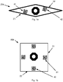
- the cutting tool 20a, 20b, 20c, 20d comprising at least a first cutting edge 21, 22 and at least a first identification marker 41, 42 arranged at the first cutting edge 21, 22.
- Figure 1a and figure 1b illustrates different cutting tools 20a, 20b according to some aspects of the disclosure.
- cutting tools are cutting inserts, milling cutters, solid end mills, turning tools, drilling tools, boaring heads, reaming tools, thread turning tools, thread milling tools, and thread tapping tools, etc.
- the at least first identification marker 41, 42 is a machine readable code associated with a first cutting tool identification data 1ctID, 2ctID.
- a first cutting tool identification data 1ctID, 2ctID is a unique identity.
- the at least first cutting tool identification data 1ctID, 2ctID is a number and/or a combination of figures and letters.
- the at least first cutting tool identification data 1ctID, 2ctID is a serial number.
- the cutting tool 20a comprising a first cutting edge 21 and a first identification marker 41 arranged at the first cutting edge 21.
- the cutting tool 20a further comprising a second cutting edge 22 and a second identification marker 42 arranged at the second cutting edge 22.
- the first cutting edge 21 can be identified using the first cutting tool identification data 1ctID and that the second cutting edge 22 can be identified using the second cutting tool identification data 2ctID.
- the different cutting edges have different identification markers and each cutting edge can be associated with individual cutting tool identification data.
- the at least first identification marker 41, 42 is at least any of, or a combination of at least any of, a two dimensional code, a three dimensional code, an image a Quick Response code, a High Capacity Colored Two Dimensional Code, a European Article Number code, a DataMatrix code or a MaxiCode.
- a two dimensional code a three dimensional code
- an image a Quick Response code a High Capacity Colored Two Dimensional Code
- a European Article Number code e.g. an operator handling the cutting tool.
- the at least first identification marker 41, 42 is an industry standard machine readable code. According to an aspect the at least first identification marker 41, 42 is a company internal machine readable code. According to an aspect the at least first identification marker 41, 42 is an open source machine readable code.
- the at least first identification marker 41, 42 is applied using different colours. According to an aspect the at least first identification marker 41, 42 is etched at the cutting tool close to the cutting edge or etched on the surface of the cutting edge.
- association between the machine readable code and the cutting edge information data is defined by a known algorithm for the specific identification marker.
- cutting edge information data is coded, using a known algorithm for a specific identification marker, which determines the appearance of the identification marker.
- the electronic device 100, 200, 300 for managing traceability of at least a first cutting tool 20a, 20b, 20c, 20d in a manufacturing process, comprises a reader device 10a, 10b, 10c configured to read information.
- the reader device 10a, 10b, 10c comprises at least one of a camera configured to obtain images and/or a radio configured to obtain information via Radio Frequency Identification technology or Near Field Communication technology.
- the reader device 10a, 10b, 10c may be a component integrated in an electronic device 100, 200, 300 or a stand-alone component. According to an aspect the electronic device 100, 200, 300 is configured to be connected with the reader device 10a, 10b, 10c. According to an aspect the electronic device 100, 200, 300 is configured to be connected to a communication network 50.
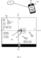
- Figure 2a and figure 2b illustrates an electronic device 100 in form of a smartphone, tablet, cellular phone, feature phone or any portable electronic device.
- the reader device 10a is the camera of a smartphone.
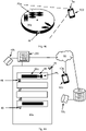
- the electronic device 200 is a part of a process step device 60a as illustrated in figure 4b .
- the reader device 10b is a stand-alone reader device connected to the electronic device 200 and installed as a part of the process step device 60a.
- the electronic device is a remote server 300 connected to a reader device 10c via a communication network 50 as illustrated in figure 4b .
- the electronic device 100, 200, 300 further comprising a memory 101a, 101b, 101c.
- one electronic device 100, 200, 300 is configured to be connected to another electronic device 100, 200, 300 via a communication network 50 as illustrated in figure 4b .
- the communication network 50 is a standardized wireless local area network such as a Wireless Local Area Network, WLAN, Bluetooth TM , ZigBee, Ultra-Wideband, Near Field Communication, NFC, Radio Frequency Identification, RFID, or similar network.
- WLAN Wireless Local Area Network
- Bluetooth TM ZigBee
- Ultra-Wideband Wireless Local Area Network
- NFC Near Field Communication
- RFID Radio Frequency Identification
- the communication network 50 is a standardized wireless wide area network such as a Global System for Mobile Communications, GSM, Extended GSM, General Packet Radio Service, GPRS, Enhanced Data Rates for GSM Evolution, EDGE, Wideband Code Division Multiple Access, WCDMA, Long Term Evolution, LTE, Narrowband-loT, 5G, Worldwide Interoperability for Microwave Access, WiMAX or Ultra Mobile Broadband, UMB or similar network.
- the communication network 50 can also be a combination of both a local area network and a wide area network.
- the communication network 50 can also be a wired network. According to an aspect the communication network 50 is defined by common Internet Protocols.
- the electronic device 100, 200, 300 is configured to be connected to a memory 101a, 101b, 101c in another electronic device 100, 200, 300 via the communication network 50.
- the electronic device 100, 200, 300 further comprises a processing circuitry 102a, 102b, 102c operatively connected to the reader device 10a, 10b, 10c.
- the processing circuitry 102a, 102b, 102c is configured to cause the electronic device 100, 200, 300 to detect, by the reader device 10a, 10b, 10c, an identification marker 41, 42 arranged at a cutting edge 21,22 of the at least first cutting tool 20a, 20b, 20c, 20d.
- the processing circuitry 102a, 102b, 102c is configured to cause the electronic device 100, 200, 300 to obtain, by the reader device 10a, 10b, 10c, information related to a first cutting tool identification marker 41, 42 of the at least first cutting tool 20a, 20b, 20c, 20d, and decode the at least first cutting tool identification marker 41, 42 to determine at least first cutting tool identification data 1ctID, 2ctID.
- the cutting tool 20a has two cutting edges 21, 22, and each cutting edge of the cutting tool 20a is associated with a cutting tool identification marker 41, 42 that can be decoded to determine a first cutting tool identification data 1ctID and a second cutting tool identification data 2ctID.
- the same cutting tool 20a is associated with a first cutting tool identification data 1ctID and a second cutting tool identification data 2ctID.
- the processing circuitry 102a, 102b, 102c is further configured to cause the electronic device 100, 200, 300 to obtain, by the reader device 10a, 10b, 10c, information related to a first carrier identification marker 43, 44 of at least a first carrier 30a, 30b configured to carry the at least first cutting tool 20a, 20b, 20c, 20d in the manufacturing process, and decode the at least first carrier identification marker 43, 44 to determine at least first carrier identification data 1cID, 2cID.
- the processing circuitry 102a, 102b, 102c is further configured to cause the electronic device 100, 200, 300 to generate a first association data 1AD indicative of the at least first cutting tool identification data 1ctID, 2ctID and the at least first carrier identification data 1cID, 2cID.
- the first association data 1AD further comprising time information data.
- the first association data 1AD is time stamped at a first point of time and further time stamped at a second point of time. In other words a certain time or a certain time period can be associated with the first association data 1AD.
- the first association data 1AD is stored in a memory 101a, 101b, 101c.
- An advantage with the first association data 1AD is that the at least first cutting tool 20a, 20b, 20c, 20d, associated with the at least first cutting tool identification data 1ctID, 2ctID, can be traced to be associated with the at least first carrier 30a, 30b. This means for example that a certain cutting tool 20a can be traced to be associated with a certain carrier 30a at a certain point of time.
- Figure 4a illustrates an example electronic device 100 that is obtaining, by the reader device 10a, information related to a carrier identification marker 44 of the carrier 30a and information related to a first cutting tool identification marker of the at least first cutting tool 20a.
- the reader device 10a, 10b, 10c is any of a camera based reader, a video camera reader, a pen-type reader with photodiodes, a laser scanner, a charge-coupled device, CCD, reader or a cell phone camera.
- the example reader device 10a of the electronic device 100 is a cell phone camera.
- the reader device 10a, 10b, 10c is a camera configured to obtain images.
- the electronic device further comprises a camera configured to obtain images.
- the processing circuitry 102a, 102b, 102c is further configured to cause the electronic device 100, 200, 300 to obtain an image of the at least first carrier 30a, 30b and the at least first cutting tool 20a, 20b, 20c, 20d.
- the processing circuitry 102a, 102b, 102c is further configured to determine, by image processing, at least a first position data 1PD, 2PD of the at least first cutting tool 20a, 20b, 20c, 20d in relation to the at least first carrier 30a, 30b, for determining the position of the at least first cutting tool 20a, 20b, 20c, 20d on the at least first carrier 30a, 30b and generate a second association data 2AD indicative of the at least first cutting tool identification data 1ctID, 2ctID and the at least first position data 1PD, 2PD.
- the processing circuitry 102a, 102b, 102c is further configured to determine, by image processing, at least a first position data 1PD, 2PD of at least a first cutting edge 21, 22 of the at least first cutting tool 20a, 20b, 20c, 20d in relation to the at least first carrier 30a, 30b, for determining the position of the at least at least first cutting edge 21, 22 of the at least first cutting tool 20a, 20b, 20c, 20d on the at least first carrier 30a, 30b and generate a second association data 2AD indicative of the at least first cutting tool identification data 1ctID, 2ctID and the at least first position data 1PD, 2PD.
- An advantage with the second association data 2AD is that the at least first cutting tool 20a, 20b, 20c, 20d, associated with the at least first cutting tool identification data 1ctID, 2ctID, can be traced to be associated with a position on the at least first carrier 30a, 30b so that it can be determined where on the at least first carrier 30a, 30b the at least first cutting tool 20a, 20b, 20c, 20d has been placed.
- the second association data 2AD is stored in a memory 101a, 101b, 101c.
- the second association data 2AD further comprising time information data.
- the second association data 2AD is time stamped at a first point of time and further time stamped at a second point of time. In other words a certain time or a certain time period can be associated with the second association data 2AD.
- the image of the at least first carrier 30a, 30b further comprising placement information for determining a relative position of the at least first cutting tool 20a, 20b, 20c, 20d on the at least first carrier 30a, 30b.
- placement information is illustrated with the letters A, B, C, and D on the carrier 30a.
- the letters A, B , C and D may be any information such as letters, figures, icons, drawings or lines that enables a relative placement information of the at least first carrier 30a, 30b.
- the at least first position data 1PD, 2PD is a two dimensional coordinate x,y for determining the position of the at least first cutting tool 20a, 20b, 20c, 20d on the at least first carrier 30a, 30b.
- a virtual two dimensional plane x,y is used for determining the position of the at least first cutting tool 20a, 20b, 20c, 20d on the at least first carrier 30a, 30b.
- the virtual two dimensional plane is determined based on placement information on the at least first carrier 30a, 30b.
- a line between the placement information A and the placement information C forms a x-axis.
- a line between the placement information D and the placement information B forms a y-axis.
- the cutting tool 20a is positioned at the position x,y on the carrier 30a.
- the virtual two dimensional plane is only displayed via a user interface 400a the electronic device 100.
- the first carrier identification marker 43, 44 further comprising a direction indication for indicating a relative direction of the at least first carrier 30a, 30b.
- a placement information can also be determined.
- decoded placement information may be a direction.
- a direction can be used to define a two dimensional plane.
- the carrier identification marker 44 is illustrated together with an arrow.
- the arrow in the identification marker 44 can in an example be a visible arrow, readable by a human eye.
- the arrow in the identification marker 44 is not visible to the human eye but only readable by the reader device 10a, 10b, 10c.
- the arrow is only displayed via a user interface 400a the electronic device 100.
- the processing circuitry 102a, 102b, 102c is further configured to cause the electronic device 100, 200, 300 to obtain an image of the at least first carrier 30a, 30b and the at least first cutting tool 20a, 20b, 20c, 20d and determine, by image processing, at least a first orientation data 1OD, 2OD of the at least first cutting tool 20a, 20b, 20c, 20d in relation to the at least first carrier 30a, 30b, for determining the orientation of the at least first cutting tool 20a, 20b, 20c, 20d on the at least first carrier 30a, 30b and generate a third association data 3AD indicative of the at least first cutting tool identification data 1ctID, 2ctID and the at least first orientation data 1OD, 2OD.
- the processing circuitry 102a, 102b, 102c is further configured to cause the electronic device 100, 200, 300 to obtain an image of the at least first carrier 30a, 30b and the at least first cutting edge 21, 22 of the at least first cutting tool 20a, 20b, 20c, 20d and determine, by image processing, at least a first orientation data 1OD, 2OD of the at least first cutting edge 21, 22 of the at least first cutting tool 20a, 20b, 20c, 20d in relation to the at least first carrier 30a, 30b, for determining the orientation of the at least first cutting edge 21, 22 of the at least first cutting tool 20a, 20b, 20c, 20d on the at least first carrier 30a, 30b and generate a third association data 3AD indicative of the at least first cutting tool identification data 1ctID, 2ctID and the at least first orientation data 1OD, 2OD.
- the third association data 3AD is further based on the at least first carrier identification data 1cID, 2cID.
- the third association data 3AD further comprising time information data.
- the third association data 3AD is time stamped at a first point of time and further time stamped at a second point of time. In other words a certain time or a certain time period can be associated with the third association data 3AD.
- the third association data 3AD is stored in a memory 101a, 101b, 101c.
- An advantage with the third association data 3AD is that the at least first cutting tool 20a, 20b, 20c, 20d, associated with the at least first cutting tool identification data 1ctID, 2ctID, can be traced to be associated with an orientation on the at least first carrier 30a, 30b so that it can be determined how the at least first cutting tool 20a, 20b, 20c, 20d has been oriented on the at least first carrier 30a, 30b.
- a plurality of cutting tools 20a, 20b, 20c, 20d are placed on the carrier 30a having different orientations.
- the orientation can be determined to be at least one of a horizontal orientation and a vertical orientation.
- a plural cutting tools are placed in a horizontal orientation, e.g. the cutting tool 20a, and a plural cutting tools are placed in a vertical orientation.
- the cutting tool 20d is orientated with a certain angle in relation to the carrier 30a.
- the orientation data 1OD, 2OD is defined by a rotation angle of the at least first cutting tool 20a, 20b, 20c, 20d in relation to the at least first carrier 30a, 30b.
- the orientation of the at least first cutting tool 20a, 20b, 20c, 20d is determined to be a number of degrees in relation to the relative placement information of the at least first carrier 30a, 30b.
- the virtual two dimensional plane x,y is used for determining the orientation of the at least first cutting tool 20a, 20b, 20c, 20d on the at least first carrier 30a, 30b.
- the orientation data 1OD, 2OD is defined by a rotation angle of the at least first cutting tool 20a, 20b, 20c, 20d around any of the x-axis or the y-axis that defines the two dimensional plane x, y of the surface of the at least first carrier 30a, 30b.
- orientation data 1OD, 2OD is further defined by a rotation angle of the at least first cutting tool 20a, 20b, 20c, 20d around an axis z that perpendicular to the x-axis and the y-axis that defines the two dimensional plane x, y of the surface of the at least first carrier 30a, 30b.
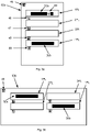
- the processing circuitry 102a, 102b, 102c is further configured to cause the electronic device 100, 200, 300 to obtain an image of the at least first carrier 30a, 30b and at least a first process step device 60a, 60b comprising at least a first placement location 1PL, 2PL, 3PL, 4PL configured to receive the at least first carrier 30a, 30b.
- the processing circuitry 102a, 102b, 102c is further configured to cause the electronic device 100, 200, 300 to determine, by image processing, at least a first placement location data 1PLD, 2PLD, 3PLD, 4PLD of the at least first carrier 30a, 30b carrying the at least first cutting tool 20a, 20b, 20c, 20d in relation to the least first placement location 1PL, 2PL, 3PL, 4PL where the at least first carrier 30a, 30b is placed, for determining the placement of the at least first carrier 30a, 30b in the at least first process step device 60a, 60b and generate a fourth association data 4AD indicative of the at least first cutting tool identification data 1ctID, 2ctID and the at least first placement location data 1PLD, 2PLD, 3PLD, 4PLD.
- the fourth association data 4AD is stored in a memory 101a, 101b, 101c According to an aspect the fourth association data 4AD further comprising time information data.
- the fourth association data 4AD is time stamped at a first point of time and further time stamped at a second point of time. In other words a certain time or a certain time period can be associated with the fourth association data 4AD.
- An advantage with the fourth association data 4AD is that the at least first carrier 30a, 30b, that is carrying the at least first cutting tool 20a, 20b, 20c, 20d associated with the at least first cutting tool identification data 1ctID, 2ctID, can further be traced to be associated with at least a first placement location data 1PLD, 2PLD, 3PLD, 4PLD for determining the placement of the at least first carrier 30a, 30b in the at least first process step device 60a, 60b.
- Figure 3a and figure 3b illustrate two example process step devices 60a, 60b.
- the process step device 60a, 60b is an oven.
- the process step device 60a, 60b is used for sintering the at least first cutting tool 20a, 20b, 20c, 20d.
- the process step device 60a, 60b is used for coating the at least first cutting tool 20a, 20b, 20c, 20d.
- the at least a first placement location data 1PLD, 2PLD, 3PLD, 4PLD is obtained by decoding an image of at least a first placement location identification marker 46, 47, 48, 49 of at the least first placement location 1PL, 2PL, 3PL, 4PL, obtained by the reader device 10a, 10b, 10c.
- each placement location 1PL, 2PL, 3PL, 4PL is associated with a placement location identification marker 46, 47, 48, 49.
- Figure 4a illustrates an example electronic device 100 that is obtaining, by the reader device 10a, information related to a carrier identification marker 44 of the carrier 30a and information related to a first cutting tool identification marker of the at least first cutting tool 20a.
- the example electronic device 100 is then further obtaining a placement location data of the carrier 30a by decoding the image of the placement location identification marker 46 and by decoding the image of the carrier identification marker 44 of the carrier 30a when placed at the first placement location 1PL.
- the carrier 30a is associated with the first placement location data 1PLD for determining the placement of the carrier 30a at the first placement location 1PL in the at least first process step device 60a.
- the processing circuitry 102a, 102b, 102c is further configured to cause the electronic device 100, 200, 300 to obtain at least a first process step identification data 1psID, 2psID and generate a fifth association data 5AD indicative of the at least first cutting tool identification data 1ctID, 2ctID and the at least first process step identification data 1psID, 2psID.
- the fifth association data 5AD is stored in a memory 101a, 101b, 101c.
- the fifth association data 5AD further comprising time information data.
- the fifth association data 5AD is time stamped at a first point of time and further time stamped at a second point of time.
- a certain time or a certain time period can be associated with the fifth association data 5AD.
- An advantage with the fifth association data 5AD is that the at least first cutting tool 20a, 20b, 20c, 20d, associated with the at least first cutting tool identification data 1ctID, 2ctID, can be traced to be associated with the at least first process step by the at least first process step identification data 1psID, 2psID.
- the at least first process step identification data 1psID, 2psID is obtained by decoding an image of at least a first process step identification marker 45 of at least a first process step device 60a, 60b, obtained by the reader device 10a, 10b, 10c.
- the at least first carrier identification marker 43, 44, at least a first process step identification marker 45, and the at least first placement location identification marker 46, 47, 48, 49 is at least any of, or a combination of at least any of, a two dimensional code, a three dimensional code, an image a Quick Response code, a High Capacity Colored Two Dimensional Code, a European Article Number code, a DataMatrix code or a MaxiCode.
- the least first process step identification data 1psID, 2psID is obtained by input of the least a first process step identification data 1psID, 2psID by an operator via a user interface 400a of the electronic device 100, 200, 300.
- processing circuitry 102a, 102b, 102c is further configured to cause the electronic device 100, 200, 300 to obtain at least a first process step sensor data 1pssD, 2pssD and generate a sixth association data 6AD indicative of the at least first cutting tool identification data 1ctID, 2ctID and the at least first process step sensor data 1pssD, 2pssD.
- the at least first process step sensor data 1pssD, 2pssD is obtained by at least a first sensor associated with at least a first process step device 60a, 60b and sent to the electronic device 100, 200, 300.
- the at least first process step sensor data 1pssD, 2pssD is any of a temperature data, a pressure data, a particle density data or a gas data.
- the sixth association data 6AD further comprising time information data.
- the sixth association data 6AD is time stamped at a first point of time and further time stamped at a second point of time. In other words a certain time or a certain time period can be associated with the sixth association data 6AD.
- the sixth association data 6AD is stored in a memory 101a, 101b, 101c.
- An advantage with the sixth association data 6AD is that the at least first cutting tool 20a, 20b, 20c, 20d, associated with the at least first cutting tool identification data 1ctID, 2ctID, can be traced to be associated with the least a first process step sensor data 1pssD, 2pssD, to e.g. understand under what circumstances the at least first cutting tool 20a, 20b, 20c, 20d has been processed.
- the processing circuitry 102a, 102b, 102c is further configured to cause the electronic device 100, 200, 300 to store the at least first association data 1AD, 2AD, 3AD, 4AD, 5AD, 6AD in a memory 101a, 101b, 101c operatively connected to the electronic device 100, 200, 300 and obtain the at least first association data 1AD, 2AD, 3AD, 4AD, 5AD, 6AD from the memory 101a, 101b, 101c by obtaining, by the reader device 10a, 10b, 10c, information related to the at least first identification marker 41, 42 of the at least first cutting tool 20a, 20b, 20c, 20d and decoding the at least first cutting tool identification marker 41, 42 to determine at least first cutting tool identification data 1ctID, 2ctID.
- the reader device 10a, 10b, 10c can be used to obtain the at least first association data 1AD, 2AD, 3AD, 4AD, 5AD, 6AD from the memory 101a, 101b, 101c in order to trace a plurality of data associated with the at least first cutting tool 20a, 20b, 20c, 20d during the manufacturing process.
- any of the at least first association data 1AD, 2AD, 3AD, 4AD, 5AD, 6AD can be obtained from the memory 101a, 101b, 101c by a request from a user via a user interface 400a of the electronic device 100, 200, 300.
- the request from a user comprising at least a first cutting tool identification data 1ctID, 2ctID.
- the disclosure further proposes a method for managing traceability of at least a first cutting tool 20a, 20b, 20c, 20d in a manufacturing process.
- Figure 5 illustrates a flow chart of the method steps according to some aspects of the disclosure.
- the method comprising the step of S1 obtaining, by a reader device 10a, 10b, 10c of an electronic device 100, 200, 300, information related to at least a first identification marker 41, 42 of the at least first cutting tool 20a, 20b, 20c, 20d and the step of S2 decoding the at least first cutting tool identification marker 41, 42 to determine at least first cutting tool identification data 1ctID, 2ctID.
- the method further comprising the step of S3 obtaining, by the reader device 10a, 10b, 10c, information related to at least a first carrier identification marker 43, 44 of at least a first carrier 30a, 30b configured to carry the at least first cutting tool 20a, 20b, 20c, 20d in the manufacturing process and the step of S4 decoding the at least first carrier identification marker 43, 44 to determine at least first carrier identification data 1cID, 2cID.
- the method further comprising the step of S5 generating a first association data 1AD indicative of the at least first cutting tool identification data 1ctID, 2ctID and the at least first carrier identification data 1cID, 2cID.
- An advantage with the first association data 1AD is that the at least first cutting tool 20a, 20b, 20c, 20d, associated with the at least first cutting tool identification data 1ctID, 2ctID, can be traced to be associated with the at least first carrier 30a, 30b. This means for example that a certain cutting tool 20a can be traced to be associated with a certain carrier 30a at a certain point of time.
- the method further comprising the step of S6 obtaining an image, of a camera configured to obtain images, of the at least first carrier 30a, 30b and the at least first cutting tool 20a, 20b, 20c, 20d and the step of S7 determining, by image processing, at least a first position data 1PD, 2PD of the at least first cutting tool 20a, 20b, 20c, 20d in relation to the at least first carrier 30a, 30b, for determining the position of the at least first cutting tool 20a, 20b, 20c, 20d on the at least first carrier 30a, 30b.
- the method further comprising the step of S8 generating a second association data 2AD indicative of the at least first cutting tool identification data 1ctID, 2ctID and the at least first position data 1PD, 2PD.
- An advantage with the second association data 2AD is that the at least first cutting tool 20a, 20b, 20c, 20d, associated with the at least first cutting tool identification data 1ctID, 2ctID, can be traced to be associated with a position on the at least first carrier 30a, 30b so that it can be determined where on the at least first carrier 30a, 30b the at least first cutting tool 20a, 20b, 20c, 20d has been placed.
- the method further comprising the step of S9 obtaining an image, of the camera configured to obtain images, of the at least first carrier 30a, 30b and the at least first cutting tool 20a, 20b, 20c, 20d and the step of S10 determining, by image processing, at least a first orientation data 1OD, 2OD of the at least first cutting tool 20a, 20b, 20c, 20d in relation to the at least first carrier 30a, 30b, for determining the orientation of the at least first cutting tool 20a, 20b, 20c, 20d on the at least first carrier 30a, 30b.
- the method further comprising the step of S11 generating a third association data 3AD indicative of the at least first cutting tool identification data 1ctID, 2ctID and the at least first orientation data 1OD, 2OD.
- An advantage with the third association data 3AD is that the at least first cutting tool 20a, 20b, 20c, 20d, associated with the at least first cutting tool identification data 1ctID, 2ctID, can be traced to be associated with an orientation on the at least first carrier 30a, 30b so that it can be determined how the at least first cutting tool 20a, 20b, 20c, 20d has been oriented on the at least first carrier 30a, 30b.
- the method further comprising the step of S12 obtaining an image, of the camera configured to obtain images, of the at least first carrier 30a, 30b and at least a first process step device 60a, 60b comprising at least a first placement location 1PL, 2PL, 3PL, 4PL configured to receive the at least first carrier 30a, 30b.
- the method further comprising the step of S13 determining, by image processing, at least a first placement location data 1PLD, 2PLD, 3PLD, 4PLD of the at least first carrier 30a, 30b carrying the at least first cutting tool 20a, 20b, 20c, 20d in relation to the least first placement location 1PL, 2PL, 3PL, 4PL where the at least first carrier 30a, 30b is placed, for determining the placement of the at least first carrier 30a, 30b in the at least first process step device 60a, 60b.
- the method then further comprising the step of S14 generating a fourth association data 4AD indicative of the at least first cutting tool identification data 1ctID, 2ctID and the at least first placement location data 1PLD, 2PLD, 3PLD, 4PLD.
- An advantage with the fourth association data 4AD is that the at least first carrier 30a, 30b, that is carrying the at least first cutting tool 20a, 20b, 20c, 20d associated with the at least first cutting tool identification data 1ctID, 2ctID, can further be traced to be associated with at least a first placement location data 1PLD, 2PLD, 3PLD, 4PLD for determining the placement of the at least first carrier 30a, 30b in the at least first process step device 60a, 60b.
- the method further comprising the step of S15 obtaining at least a first process step identification data 1psID, 2psID and the step of S16 generating a fifth association data 5AD indicative of the at least first cutting tool identification data 1ctID, 2ctID and the at least first process step identification data 1psID, 2psID.
- An advantage with the fifth association data 5AD is that the at least first cutting tool 20a, 20b, 20c, 20d, associated with the at least first cutting tool identification data 1ctID, 2ctID, can be traced to be associated with the at least first process step by the at least first process step identification data 1psID, 2psID.
- the method further comprising the step of S17 obtaining at least a first process step sensor data 1pssD, 2pssD and the step of S18 generating a sixth association data 6AD indicative of the at least first cutting tool identification data 1ctID, 2ctID and the at least first process step sensor data 1pssD, 2pssD.
- a sixth association data 6AD indicative of the at least first cutting tool identification data 1ctID, 2ctID and the at least first process step sensor data 1pssD, 2pssD.
- the method further comprising the step of S19 storing the at least first association data 1AD, 2AD, 3AD, 4AD, 5AD, 6AD in a memory 101a, 101b, 101c operatively connected to the electronic device 100, 200, 300 and the step of S20 obtaining the at least first association data 1AD, 2AD, 3AD, 4AD, 5AD, 6AD from the memory 101a, 101b, 101c by obtaining, by the reader device 10a, 10b, 10c, information related to the at least first identification marker 41, 42 of the at least first cutting tool 20a, 20b, 20c, 20d and decoding the at least first cutting tool identification marker 41, 42 to determine at least first cutting tool identification data 1ctID, 2ctID.
- the reader device 10a, 10b, 10c can be used to obtain the at least first association data 1AD, 2AD, 3AD, 4AD, 5AD, 6AD from the memory 101a, 101b, 101c in order to trace a plurality of data associated with the at least first cutting tool 20a, 20b, 20c, 20d during the manufacturing process.
- the disclosure further proposes, as illustrated in figure 6 , a computer program product 500 comprising a non-transitory computer readable medium, having thereon a computer program comprising program instructions, the computer program being loadable into a processing circuitry 102a, 102b, 102c and configured to cause execution of the method, and any aspect of the method, when the computer program is run by the processing circuitry 102a, 102b, 102c.
- the electronic device 100, 200, 300 is configured to carry out any or more of the aspects of the described method. According to an aspect of the disclosure, the method is carried out by instructions in a software program that is downloaded and run in the electronic device 100, 200, 300.
Description
- The disclosure pertains to the field of a manufacturing process of a cutting tool.
- A cutting tool may comprise one or more cutting edges that are used for removing chips from a piece of material. Typically a cutting tool is inserted into a cutting tool holder and a machine is e.g. rotating the cutting tool holder together with the cutting tool for processing the piece of material. The piece of material is processed when a cutting edge of the cutting tool comes in contact with the piece of material. A cutting tool may comprise one or more cutting edges that are used for removing chips from the piece of material that is being processed by the cutting tool.
- When a cutting tool is manufactured, the cutting tool passes a number of manufacturing steps. In different manufacturing steps, the cutting tool is processed in different ways. Today most operations within different manufacturing process steps when manufacturing cutting tools, are completely disconnected from each other. This means that information from one manufacturing process step is not linked to the cutting tool, and hence not linked to the next manufacturing process step. In the case a problem occurs in a manufacturing process step, the problem is often dealt with at that specific manufacturing process step. However, if a problem occurs with a cutting tool after it has left the manufacturing process, e.g. when the cutting tool is used for processing a piece of material, is can be difficult to understand where in the manufacturing process, in what process step, something went wrong when manufacturing the cutting tool. In the best case, a manual review of manufacturing protocols, may reveal the cause of the problem. However, such manufacturing protocols are sometimes handwritten and it may not always be easy to understand the circumstances at a specific manufacturing process step when the cutting tool was manufactured.
-
WO 2018/169824 A1 (CARBON INC [US]) 20 September 2018 (2018-09-20) discloses an integrated additive manufacturing system. The system comprising at least one resin supply, a plurality of additive manufacturing machines on which parts may be produced, each of the additive manufacturing machines operatively associated with at least one resin supply, and at least one peripheral machine operatively associated with each of the additive manufacturing machines and the at least one resin supply. The system comprises unique identifiers such as NFC tags, RFID tags and/ or bar codes which can be read by an associated reader device. A build plate (or "window") on which resin is dispensed is provided with a unique identifier. The build plate is transferred with the resin to an additive manufacturing machine. Each part produced on an additive manufacturing machine can also have its own unique identifier. A peripheral machine, e.g. an oven, can be provided with a reader for reading the unique identifiers of the parts and the "window". In this way oven data can be associated with a particular "window" and particular parts in a database. Examples of information that can be stored with the unique identifier are build platform and/or window cassette position identity (i.e. an indication of the specific location on a "window" on which a particular part was produced, particularly useful when multiple parts are concurrently produced at the same time on the same build platform); window cassette unique identity; and date of production. -
US 2014/195031 A1 (COUSE STEPHEN [US] ET AL) 10 July 2014 (2014-07-10) discloses systems and methods for fuel cell stack part serialization and tracking. In an embodiment, a barcode may be applied to a fuel cell stack part which may identify the fuel cell stack part. In an embodiment, the barcode may be applied as ink on a green fuel cell stack part prior to sintering. In an embodiment, a portion of a fuel cell stack part may be imaged, and pattern recognition techniques may be utilized to identify the fuel cell stack part based on the unique features of fuel cell stack part. In an embodiment, portion of a fuel cell stack part may be measured to generate one or more series of unique volume/area values and one or more series of unique volume/area values may be utilized to identify the fuel cell stack part. - The invention is defined by the device of
claim 1, the method of claim 6, and the computer program product of claim 11. Optional aspects of the invention are defined in the dependent claims. - The foregoing will be apparent from the following more particular description of the example embodiments, as illustrated in the accompanying drawings in which like reference characters refer to the same parts throughout the different views. The drawings are not necessarily to scale, emphasis instead being placed upon illustrating the example embodiments.
-
Figure 1a and figure 1b illustrates different cutting tools according to some aspects of the disclosure. -
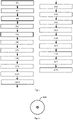
Figure 2a andfigure 2b illustrates different carriers and an electronic device according to some aspects of the disclosure. -
Figure 3a and figure 3b illustrates different process step devices with different placement locations according to some aspects of the disclosure. -
Figure 4a illustrates a carrier and an electronic device according to some aspects of the disclosure. -
Figure 4b illustrates a process step device and an electronic device according to some aspects of the disclosure. -
Figure 5 illustrates a flow chart of the method steps according to some aspects of the disclosure. -
Figure 6 illustrates a computer program product according to some aspects of the disclosure. - Aspects of the present disclosure will be described more fully hereinafter with reference to the accompanying drawings. The method and device disclosed herein can, however, be realized in many different forms and should not be construed as being limited to the aspects set forth herein, but by the appended claims. Like numbers in the drawings refer to like elements throughout.
- The terminology used herein is for the purpose of describing particular aspects of the disclosure only, and is not intended to limit the disclosure. As used herein, the singular forms "a", "an" and "the" are intended to include the plural forms as well, unless the context clearly indicates otherwise.
- In some implementations and according to some aspects of the disclosure, the functions or steps noted in the blocks can occur out of the order noted in the operational illustrations. For example, two blocks shown in succession can in fact be executed substantially concurrently or the blocks can sometimes be executed in the reverse order, depending upon the functionality/acts involved.
- In the drawings and specification, there have been disclosed exemplary aspects of the disclosure. However, many variations and modifications can be made to these aspects without substantially departing from the principles of the present disclosure. Thus, the disclosure should be regarded as illustrative rather than restrictive, and not as being limited to the particular aspects discussed above. Accordingly, although specific terms are employed, they are used in a generic and descriptive sense only and not for purposes of limitation.
- It should be noted that the word "comprising" does not necessarily exclude the presence of other elements or steps than those listed and the words "a" or "an" preceding an element do not exclude the presence of a plurality of such elements. It should further be noted that any reference signs do not limit the scope of the claims, that the example embodiments may be implemented at least in part by means of both hardware and software, and that several "means", "units" or "devices" may be represented by the same item of hardware.
- There is a demand for an easier way to manage traceability of a cutting tool in a manufacturing process of the cutting tool. In particular, the inventors have identified that there is a demand for understanding the specific position and orientation of a specific cutting tool on a specific carrier that is used to carry the cutting tools through a certain process step, or process steps, when manufacturing the cutting tool. Such information from each process step can then be used in the assessment of identifying a reason to a potential problem with a cutting tool at a later stage. The information can also be used as input to a succeeding process step to e.g. adjust parameters of settings in the succeeding process step dependent in the information from the previous process step. Both manufacturers of cutting tools and end-customers of the cutting tools benefit from understanding production information details that are associated with each cutting tool throughout the lifetime of each cutting tool. These details can e.g. help the manufacturer to improve the manufacturing of the cutting tools.
- An object of the present disclosure is to provide an electronic device, a method and computer program product which seek to mitigate, alleviate, or eliminate one or more of the above-identified deficiencies in the art and disadvantages singly or in any combination.
- The disclosure proposes an
electronic device first cutting tool first cutting tool first cutting edge first cutting tool first cutting edge - According to an aspect, the
cutting tool first cutting edge first identification marker first cutting edge -
Figure 1a and figure 1b illustratesdifferent cutting tools - According to an aspect, the at least
first identification marker first cutting edge - In the example illustration in
figure 1a , thecutting tool 20a comprising afirst cutting edge 21 and afirst identification marker 41 arranged at thefirst cutting edge 21. According to an aspect thecutting tool 20a further comprising asecond cutting edge 22 and asecond identification marker 42 arranged at thesecond cutting edge 22. This means that thefirst cutting edge 21 can be identified using the first cutting tool identification data 1ctID and that thesecond cutting edge 22 can be identified using the second cutting tool identification data 2ctID. In other words the different cutting edges have different identification markers and each cutting edge can be associated with individual cutting tool identification data. - According to an aspect the at least
first identification marker first identification marker cutting tool 20a by a machine but also visually detectable by e.g. an operator handling the cutting tool. - According to an aspect the at least
first identification marker first identification marker first identification marker - According to an aspect the at least
first identification marker first identification marker - According to an aspect the association between the machine readable code and the cutting edge information data is defined by a known algorithm for the specific identification marker. According to an aspect cutting edge information data is coded, using a known algorithm for a specific identification marker, which determines the appearance of the identification marker.
- The
electronic device first cutting tool reader device reader device - The
reader device electronic device electronic device reader device electronic device communication network 50. -
Figure 2a andfigure 2b illustrates anelectronic device 100 in form of a smartphone, tablet, cellular phone, feature phone or any portable electronic device. In one example, as illustrated infigure 2a and infigure 2b , thereader device 10a is the camera of a smartphone. - In an example the
electronic device 200 is a part of aprocess step device 60a as illustrated infigure 4b . In an example, illustrated infigure 4b , thereader device 10b is a stand-alone reader device connected to theelectronic device 200 and installed as a part of theprocess step device 60a. According to an aspect the electronic device is aremote server 300 connected to areader device 10c via acommunication network 50 as illustrated infigure 4b . - According to an aspect the
electronic device memory electronic device electronic device communication network 50 as illustrated infigure 4b . - In one example the
communication network 50, as illustrated infigure 2a ,figure 2b andfigure 4b , is a standardized wireless local area network such as a Wireless Local Area Network, WLAN, Bluetooth™, ZigBee, Ultra-Wideband, Near Field Communication, NFC, Radio Frequency Identification, RFID, or similar network. In one example thecommunication network 50 is a standardized wireless wide area network such as a Global System for Mobile Communications, GSM, Extended GSM, General Packet Radio Service, GPRS, Enhanced Data Rates for GSM Evolution, EDGE, Wideband Code Division Multiple Access, WCDMA, Long Term Evolution, LTE, Narrowband-loT, 5G, Worldwide Interoperability for Microwave Access, WiMAX or Ultra Mobile Broadband, UMB or similar network. Thecommunication network 50 can also be a combination of both a local area network and a wide area network. Thecommunication network 50 can also be a wired network. According to an aspect thecommunication network 50 is defined by common Internet Protocols. - According to an aspect the
electronic device memory electronic device communication network 50. - The
electronic device processing circuitry reader device - According to an aspect the
processing circuitry electronic device reader device identification marker cutting edge first cutting tool - The
processing circuitry electronic device reader device tool identification marker first cutting tool tool identification marker figure 1a , thecutting tool 20a has twocutting edges cutting tool 20a is associated with a cuttingtool identification marker same cutting tool 20a is associated with a first cutting tool identification data 1ctID and a second cutting tool identification data 2ctID. - The
processing circuitry electronic device reader device carrier identification marker first carrier first cutting tool carrier identification marker processing circuitry electronic device memory first cutting tool first carrier certain cutting tool 20a can be traced to be associated with acertain carrier 30a at a certain point of time. -
Figure 4a illustrates an exampleelectronic device 100 that is obtaining, by thereader device 10a, information related to acarrier identification marker 44 of thecarrier 30a and information related to a first cutting tool identification marker of the at leastfirst cutting tool 20a. - According to an aspect the
reader device figure 4a , theexample reader device 10a of theelectronic device 100 is a cell phone camera. - According to an aspect the
reader device processing circuitry electronic device first carrier first cutting tool processing circuitry first cutting tool first carrier first cutting tool first carrier - According to an aspect, the
processing circuitry first cutting edge first cutting tool first carrier first cutting edge first cutting tool first carrier - An advantage with the second association data 2AD is that the at least
first cutting tool first carrier first carrier first cutting tool memory - According to an aspect the image of the at least
first carrier first cutting tool first carrier figure 2a andfigure 2b , placement information is illustrated with the letters A, B, C, and D on thecarrier 30a. In the example the letters A, B , C and D may be any information such as letters, figures, icons, drawings or lines that enables a relative placement information of the at leastfirst carrier - According to an aspect the at least first position data 1PD, 2PD is a two dimensional coordinate x,y for determining the position of the at least
first cutting tool first carrier - According to an aspect, as illustrated in
figure 2a andfigure 2b , a virtual two dimensional plane x,y is used for determining the position of the at leastfirst cutting tool first carrier first carrier figure 2a andfigure 2b , a line between the placement information A and the placement information C forms a x-axis. In an example, as visualised infigure 2a andfigure 2b , a line between the placement information D and the placement information B forms a y-axis. In an example as visualised infigure 2a andfigure 2b , thecutting tool 20a is positioned at the position x,y on thecarrier 30a. In an example the virtual two dimensional plane is only displayed via auser interface 400a theelectronic device 100. - According to an aspect, the first
carrier identification marker first carrier carrier identification marker figure 2a , thecarrier identification marker 44 is illustrated together with an arrow. The arrow in theidentification marker 44 can in an example be a visible arrow, readable by a human eye. In an example the arrow in theidentification marker 44 is not visible to the human eye but only readable by thereader device user interface 400a theelectronic device 100. - According to an aspect the
processing circuitry electronic device first carrier first cutting tool first cutting tool first carrier first cutting tool first carrier - According to an aspect the
processing circuitry electronic device first carrier first cutting edge first cutting tool first cutting edge first cutting tool first carrier first cutting edge first cutting tool first carrier - According to an aspect the third association data 3AD is further based on the at least first carrier identification data 1cID, 2cID.
- According to an aspect the third association data 3AD further comprising time information data. In an example the third association data 3AD is time stamped at a first point of time and further time stamped at a second point of time. In other words a certain time or a certain time period can be associated with the third association data 3AD. According to an aspect the third association data 3AD is stored in a
memory first cutting tool first carrier first cutting tool first carrier - In the example as visualised in
figure 2a , a plurality ofcutting tools carrier 30a having different orientations. According to an aspect the orientation can be determined to be at least one of a horizontal orientation and a vertical orientation. In the example illustrated infigure 2a a plural cutting tools are placed in a horizontal orientation, e.g. thecutting tool 20a, and a plural cutting tools are placed in a vertical orientation. In thefigure 2a thecutting tool 20d is orientated with a certain angle in relation to thecarrier 30a. - According to an aspect the orientation data 1OD, 2OD is defined by a rotation angle of the at least
first cutting tool first carrier first cutting tool first carrier - According to an aspect, the virtual two dimensional plane x,y is used for determining the orientation of the at least
first cutting tool first carrier first cutting tool first carrier - According to an aspect the orientation data 1OD, 2OD is further defined by a rotation angle of the at least
first cutting tool first carrier - According to an aspect the
processing circuitry electronic device first carrier process step device first carrier processing circuitry electronic device first carrier first cutting tool first carrier first carrier process step device - According to an aspect the fourth association data 4AD is stored in a
memory first carrier first cutting tool first carrier process step device -
Figure 3a and figure 3b illustrate two exampleprocess step devices process step device process step device first cutting tool process step device first cutting tool - According to an aspect the at least a first placement location data 1PLD, 2PLD, 3PLD, 4PLD is obtained by decoding an image of at least a first placement
location identification marker reader device figure 3a and figure 3b , each placement location 1PL, 2PL, 3PL, 4PL is associated with a placementlocation identification marker -
Figure 4a illustrates an exampleelectronic device 100 that is obtaining, by thereader device 10a, information related to acarrier identification marker 44 of thecarrier 30a and information related to a first cutting tool identification marker of the at leastfirst cutting tool 20a. Infigure 4b the exampleelectronic device 100 is then further obtaining a placement location data of thecarrier 30a by decoding the image of the placementlocation identification marker 46 and by decoding the image of thecarrier identification marker 44 of thecarrier 30a when placed at the first placement location 1PL. In the example infigure 4b , thecarrier 30a is associated with the first placement location data 1PLD for determining the placement of thecarrier 30a at the first placement location 1PL in the at least firstprocess step device 60a. - According to an aspect the
processing circuitry electronic device memory first cutting tool - According to an aspect the at least first process step identification data 1psID, 2psID is obtained by decoding an image of at least a first process
step identification marker 45 of at least a firstprocess step device reader device - According to an aspect the at least first
carrier identification marker step identification marker 45, and the at least first placementlocation identification marker - According to an aspect the least first process step identification data 1psID, 2psID is obtained by input of the least a first process step identification data 1psID, 2psID by an operator via a
user interface 400a of theelectronic device - According to an aspect the
processing circuitry electronic device - According to an aspect the at least first process step sensor data 1pssD, 2pssD is obtained by at least a first sensor associated with at least a first
process step device electronic device memory - An advantage with the sixth association data 6AD is that the at least
first cutting tool first cutting tool - According to an aspect the
processing circuitry electronic device memory electronic device memory reader device first identification marker first cutting tool tool identification marker first cutting tool reader device memory first cutting tool memory user interface 400a of theelectronic device - The disclosure further proposes a method for managing traceability of at least a
first cutting tool Figure 5 illustrates a flow chart of the method steps according to some aspects of the disclosure. - The method comprising the step of S1 obtaining, by a
reader device electronic device first identification marker first cutting tool tool identification marker reader device carrier identification marker first carrier first cutting tool carrier identification marker first cutting tool first carrier certain cutting tool 20a can be traced to be associated with acertain carrier 30a at a certain point of time. - According to an aspect the method further comprising the step of S6 obtaining an image, of a camera configured to obtain images, of the at least
first carrier first cutting tool first cutting tool first carrier first cutting tool first carrier first cutting tool first carrier first carrier first cutting tool - According to an aspect the method further comprising the step of S9 obtaining an image, of the camera configured to obtain images, of the at least
first carrier first cutting tool first cutting tool first carrier first cutting tool first carrier first cutting tool first carrier first cutting tool first carrier - According to an aspect the method further comprising the step of S12 obtaining an image, of the camera configured to obtain images, of the at least
first carrier process step device first carrier first carrier first cutting tool first carrier first carrier process step device first carrier first cutting tool first carrier process step device - According to an aspect the method further comprising the step of S15 obtaining at least a first process step identification data 1psID, 2psID and the step of S16 generating a fifth association data 5AD indicative of the at least first cutting tool identification data 1ctID, 2ctID and the at least first process step identification data 1psID, 2psID. An advantage with the fifth association data 5AD is that the at least
first cutting tool - According to an aspect the method further comprising the step of S17 obtaining at least a first process step sensor data 1pssD, 2pssD and the step of S18 generating a sixth association data 6AD indicative of the at least first cutting tool identification data 1ctID, 2ctID and the at least first process step sensor data 1pssD, 2pssD. An advantage with the sixth association data 6AD is that the at least
first cutting tool first cutting tool - According to an aspect the method further comprising the step of S19 storing the at least first association data 1AD, 2AD, 3AD, 4AD, 5AD, 6AD in a
memory electronic device memory reader device first identification marker first cutting tool tool identification marker first cutting tool reader device memory first cutting tool - The disclosure further proposes, as illustrated in
figure 6 , acomputer program product 500 comprising a non-transitory computer readable medium, having thereon a computer program comprising program instructions, the computer program being loadable into aprocessing circuitry processing circuitry - According to an aspect the
electronic device electronic device - In the drawings and specification, there have been disclosed exemplary embodiments. However, many variations and modifications can be made to these embodiments, within the scope of the appended claims. Accordingly, although specific terms are employed, they are used in a generic and descriptive sense only and not for purposes of limitation, the scope of the embodiments being defined by the following claims.
Claims (11)
- An electronic device (100, 200, 300) for managing traceability of at least a first cutting tool (20a, 20b, 20c, 20d) in a manufacturing process of said tool, the electronic device (100, 200, 300) comprises:• a reader device (10a, 10b, 10c) configured to read information;• a processing circuitry (102a, 102b, 102c) operatively connected to the reader device (10a, 10b, 10c) configured to cause the electronic device (100, 200, 300) to:the reader device (10a, 10b, 10c) is a camera configured to obtain images, or wherein the electronic device further comprises a camera configured to obtain images, and the processing circuitry (102a, 102b, 102c) is further configured to cause the electronic device (100, 200, 300) to:- obtain, by the reader device (10a, 10b, 10c), information related to a first cutting tool identification marker (41, 42) of the at least first cutting tool (20a, 20b, 20c, 20d);- decode the at least first cutting tool identification marker (41, 42) to determine at least first cutting tool identification data (1ctID, 2ctID);- obtain, by the reader device (10a, 10b, 10c), information related to a first carrier identification marker (43, 44) of at least a first carrier (30a, 30b) configured to carry the at least first cutting tool (20a, 20b, 20c, 20d) in the manufacturing process;- decode the at least first carrier identification marker (43, 44) to determine at least first carrier identification data (1cID, 2cID); and- generate a first association data (1AD) indicative of the at least first cutting tool identification data (1ctID, 2ctID) and the at least first carrier identification data (1cID, 2cID); wherein- obtain an image of the at least first carrier (30a, 30b) and the at least first cutting tool (20a, 20b, 20c, 20d);- determine, by image processing, at least a first position data (1PD, 2PD) of the at least first cutting tool (20a, 20b, 20c, 20d) in relation to the at least first carrier (30a, 30b), for determining the position of the at least first cutting tool (20a, 20b, 20c, 20d) on the at least first carrier (30a, 30b); and- generate a second association data (2AD) indicative of the at least first cutting tool identification data (1ctID, 2ctID) and the at least first position data (1PD, 2PD); characterized in thatthe processing circuitry (102a, 102b, 102c) is further configured to cause the electronic device (100, 200, 300) to:- obtain an image of the at least first carrier (30a, 30b) and at least a first process step device (60a, 60b) comprising at least a first placement location (1PL, 2PL, 3PL, 4PL) configured to receive the at least first carrier (30a, 30b);- determine, by image processing, at least a first placement location data (1PLD, 2PLD, 3PLD, 4PLD) of the at least first carrier (30a, 30b) carrying the at least first cutting tool (20a, 20b, 20c, 20d) in relation to the at least first placement location (1PL, 2PL, 3PL, 4PL) where the at least first carrier (30a, 30b) is placed, for determining the placement of the at least first carrier (30a, 30b) in the at least first process step device (60a, 60b); and- generate a fourth association data (4AD) indicative of the at least first cutting tool identification data (1ctID, 2ctID) and the at least first placement location data (1PLD, 2PLD, 3PLD, 4PLD).
- The electronic device (100, 200, 300) according to claim 1, wherein the processing circuitry (102a, 102b, 102c) is further configured to cause the electronic device (100, 200, 300) to:- obtain an image of the at least first carrier (30a, 30b) and the at least first cutting tool (20a, 20b, 20c, 20d);- determine, by image processing, at least a first orientation data (1OD, 2OD) of the at least first cutting tool (20a, 20b, 20c, 20d) in relation to the at least first carrier (30a, 30b), for determining the orientation of the at least first cutting tool (20a, 20b, 20c, 20d) on the at least first carrier (30a, 30b); and- generate a third association data (3AD) indicative of the at least first cutting tool identification data (1ctID, 2ctID) and the at least first orientation data (1OD, 20D).
- The electronic device (100, 200, 300) according to any of the preceding claims, wherein the processing circuitry (102a, 102b, 102c) is further configured to cause the electronic device (100, 200, 300) to:- obtain at least a first process step identification data (1psID, 2psID); and- generate a fifth association data (5AD) indicative of the at least first cutting tool identification data (1ctID, 2ctID) and the at least first process step identification data (1psID, 2psID).
- The electronic device (100, 200, 300) according to any of the preceding claims, wherein the processing circuitry (102a, 102b, 102c) is further configured to cause the electronic device (100, 200, 300) to:- obtain at least a first process step sensor data (1pssD, 2pssD); and- generate a sixth association data (6AD) indicative of the at least first cutting tool identification data (1ctID, 2ctID) and the at least first process step sensor data (1pssD, 2pssD).
- The electronic device (100, 200, 300) according to any of the preceding claims, wherein the processing circuitry (102a, 102b, 102c) is further configured to cause the electronic device (100, 200, 300) to:- store the at least first association data (1AD, 2AD, 3AD, 4AD, 5AD, 6AD) in a memory (101a, 101b, 101c) operatively connected to the electronic device (100, 200, 300); and- obtain the at least first association data (1AD, 2AD, 3AD, 4AD, 5AD, 6AD) from the memory (101a, 101b, 101c) by obtaining, by the reader device (10a, 10b, 10c), information related to the at least first identification marker (41, 42) of the at least first cutting tool (20a, 20b, 20c, 20d) and decoding the at least first cutting tool identification marker (41, 42) to determine at least first cutting tool identification data (1ctID, 2ctID).
- A method for managing traceability of at least a first cutting tool (20a, 20b, 20c, 20d) in a manufacturing process of said tool, the method executed by the electronic device (100, 200, 300) of claim 1, the method comprising:- (S1) obtaining, by a reader device (10a, 10b, 10c) of said electronic device (100, 200, 300), comprising a processing circuitry (102a, 102b, 102c) operatively connected to the reader device (10a, 10b, 10c), information related to at least a first identification marker (41, 42) of the at least first cutting tool (20a, 20b, 20c, 20d);- (S2) decoding the at least first cutting tool identification marker (41, 42) to determine at least first cutting tool identification data (1ctID, 2ctID);- (S3) obtaining, by the reader device (10a, 10b, 10c), information related to at least a first carrier identification marker (43, 44) of at least a first carrier (30a, 30b) configured to carry the at least first cutting tool (20a, 20b, 20c, 20d) in the manufacturing process;- (S4) decoding the at least first carrier identification marker (43, 44) to determine at least first carrier identification data (1cID, 2cID); and- (S5) generating a first association data (1AD) indicative of the at least first cutting tool identification data (1ctID, 2ctID) and the at least first carrier identification data (1cID, 2cID);- (S8) obtaining an image, of a camera configured to obtain images, of the at least first carrier (30a, 30b) and the at least first cutting tool (20a, 20b, 20c, 20d);- (S9) determining, by image processing, at least a first position data (1PD, 2PD) of the at least first cutting tool (20a, 20b, 20c, 20d) in relation to the at least first carrier (30a, 30b), for determining the position of the at least first cutting tool (20a, 20b, 20c, 20d) on the at least first carrier (30a, 30b); and- (S10) generating a second association data (2AD) indicative of the at least first cutting tool identification data (1ctID, 2ctID) and the at least first position data (1PD, 2PD); characterized in that the method further comprising- (S14) obtaining an image, of the camera configured to obtain images, of the at least first carrier (30a, 30b) and at least a first process step device (60a, 60b) comprising at least a first placement location (1PL, 2PL, 3PL, 4PL) configured to receive the at least first carrier (30a, 30b);- (S15) determining, by image processing, at least a first placement location data (1PLD, 2PLD, 3PLD, 4PLD) of the at least first carrier (30a, 30b) carrying the at least first cutting tool (20a, 20b, 20c, 20d) in relation to the at least first placement location (1PL, 2PL, 3PL, 4PL) where the at least first carrier (30a, 30b) is placed, for determining the placement of the at least first carrier (30a, 30b) in the at least first process step device (60a, 60b); and- (S16) generating a fourth association data (4AD) indicative of the at least first cutting tool identification data (1ctID, 2ctID) and the at least first placement location data (1PLD, 2PLD, 3PLD, 4PLD).
- The method according to claim 6, further comprising :- (S11) obtaining an image, of the camera configured to obtain images, of the at least first carrier (30a, 30b) and the at least first cutting tool (20a, 20b, 20c, 20d);- (S12) determining, by image processing, at least a first orientation data (1OD, 2OD) of the at least first cutting tool (20a, 20b, 20c, 20d) in relation to the at least first carrier (30a, 30b), for determining the orientation of the at least first cutting tool (20a, 20b, 20c, 20d) on the at least first carrier (30a, 30b); and- (S13) generating a third association data (3AD) indicative of the at least first cutting tool identification data (1ctID, 2ctID) and the at least first orientation data (1OD, 20D).
- The method according to claim 6 or 7, further comprising :- (S17) obtaining at least a first process step identification data (1psID, 2psID); and- (S18) generating a fifth association data (5AD) indicative of the at least first cutting tool identification data (1ctID, 2ctID) and the at least first process step identification data (1psID, 2psID).
- The method according to any of the claims 6-8, further comprising :- (S19) obtaining at least a first process step sensor data (1pssD, 2pssD); and- (S20) generating a sixth association data (6AD) indicative of the at least first cutting tool identification data (1ctID, 2ctID) and the at least first process step sensor data (1pssD, 2pssD).
- The method according to any of the claims 6-9, further comprising :- storing the at least first association data (1AD, 2AD, 3AD, 4AD, 5AD, 6AD) in a memory (101a, 101b, 101c) operatively connected to the electronic device (100, 200, 300); and- obtaining the at least first association data (1AD, 2AD, 3AD, 4AD, 5AD, 6AD) from the memory (101a, 101b, 101c) by obtaining, by the reader device (10a, 10b, 10c), information related to the at least first identification marker (41, 42) of the at least first cutting tool (20a, 20b, 20c, 20d) and decoding the at least first cutting tool identification marker (41, 42) to determine at least first cutting tool identification data (1ctID, 2ctID).
- A computer program product (500) comprising a non-transitory computer readable medium, having thereon a computer program comprising program instructions, the computer program being loadable into the processing circuitry (102a, 102b, 102c) of an electronic device (100, 200, 300) according to claim 1 and configured to cause execution of the method according to any of claims 6-10 when the computer program is run by the processing circuitry (102a, 102b, 102c) of said electronic device (100, 200, 300) according to claim 1.
Priority Applications (6)
| Application Number | Priority Date | Filing Date | Title |
|---|---|---|---|
| EP19183272.4A EP3757697B1 (en) | 2019-06-28 | 2019-06-28 | An electronic device and method for managing traceability of a cutting tool |
| JP2021577464A JP2022538611A (en) | 2019-06-28 | 2020-06-11 | Electronic device and method for managing traceability of cutting tools |
| US17/622,574 US20220253046A1 (en) | 2019-06-28 | 2020-06-11 | Electronic device and method for managing traceability of a cutting tool |
| PCT/EP2020/066169 WO2020260030A1 (en) | 2019-06-28 | 2020-06-11 | An electronic device and method for managing traceability of a cutting tool |
| CN202080039947.7A CN113906354B (en) | 2019-06-28 | 2020-06-11 | Electronic device and method for managing traceability of cutting tools |
| KR1020217042139A KR20220027862A (en) | 2019-06-28 | 2020-06-11 | Electronic devices and methods for managing traceability of cutting tools |
Applications Claiming Priority (1)
| Application Number | Priority Date | Filing Date | Title |
|---|---|---|---|
| EP19183272.4A EP3757697B1 (en) | 2019-06-28 | 2019-06-28 | An electronic device and method for managing traceability of a cutting tool |
Publications (2)
| Publication Number | Publication Date |
|---|---|
| EP3757697A1 EP3757697A1 (en) | 2020-12-30 |
| EP3757697B1 true EP3757697B1 (en) | 2022-08-10 |
Family
ID=67383700
Family Applications (1)
| Application Number | Title | Priority Date | Filing Date |
|---|---|---|---|
| EP19183272.4A Active EP3757697B1 (en) | 2019-06-28 | 2019-06-28 | An electronic device and method for managing traceability of a cutting tool |
Country Status (6)
| Country | Link |
|---|---|
| US (1) | US20220253046A1 (en) |
| EP (1) | EP3757697B1 (en) |
| JP (1) | JP2022538611A (en) |
| KR (1) | KR20220027862A (en) |
| CN (1) | CN113906354B (en) |
| WO (1) | WO2020260030A1 (en) |
Families Citing this family (1)
| Publication number | Priority date | Publication date | Assignee | Title |
|---|---|---|---|---|
| WO2023033190A1 (en) * | 2021-09-02 | 2023-03-09 | キヤノン株式会社 | Management system |
Family Cites Families (13)
| Publication number | Priority date | Publication date | Assignee | Title |
|---|---|---|---|---|
| US3543392A (en) * | 1967-12-15 | 1970-12-01 | Cincinnati Milacron Inc | Machine tools having conveyor means extending therebetween and carrying pallet means which are selectively connectable to the machine tools |
| CN101488017B (en) * | 2009-02-24 | 2010-11-17 | 上海奈凯电子科技有限公司 | Real-time control method of process tool route of numerical control machine based on machine vision |
| WO2012061890A1 (en) * | 2010-11-10 | 2012-05-18 | Interactive Machine Systems Pty Limited | Assistance system for steering a machine tool |
| WO2012069284A1 (en) * | 2010-11-25 | 2012-05-31 | Komet Group Gmbh | Server of a computer network |
| US9678501B2 (en) * | 2013-01-08 | 2017-06-13 | Bloom Energy Corporation | Serialization of fuel cell components |
| US9817387B2 (en) * | 2013-07-08 | 2017-11-14 | Kennametal Inc | System and method for selecting a tool assembly |
| US20150025672A1 (en) * | 2013-07-18 | 2015-01-22 | Kennametal Inc. | System and method for selecting cutting tools |
| JP5850003B2 (en) * | 2013-07-26 | 2016-02-03 | 株式会社安川電機 | Robot system, robot management computer for robot system, and robot system management method |
| WO2018169826A1 (en) * | 2017-03-15 | 2018-09-20 | Carbon, Inc. | Integrated additive manufacturing systems incorporating identification structures |
| JP6972738B2 (en) * | 2017-07-28 | 2021-11-24 | 富士フイルムビジネスイノベーション株式会社 | Information processing equipment and programs |
| CN111836712B (en) * | 2017-10-23 | 2023-04-11 | 卡本有限公司 | Window variability correction in additive manufacturing |
| CN109746767A (en) * | 2019-02-28 | 2019-05-14 | 中车青岛四方机车车辆股份有限公司 | The application method and cutter of a kind of management-control method of cutter, cutter |
| EP3733332B1 (en) * | 2019-04-30 | 2022-11-09 | Seco Tools Ab | A cutting tool, system and method for increasing traceability of a cutting edge |
-
2019
- 2019-06-28 EP EP19183272.4A patent/EP3757697B1/en active Active
-
2020
- 2020-06-11 WO PCT/EP2020/066169 patent/WO2020260030A1/en active Application Filing
- 2020-06-11 US US17/622,574 patent/US20220253046A1/en active Pending
- 2020-06-11 KR KR1020217042139A patent/KR20220027862A/en unknown
- 2020-06-11 CN CN202080039947.7A patent/CN113906354B/en active Active
- 2020-06-11 JP JP2021577464A patent/JP2022538611A/en active Pending
Also Published As
| Publication number | Publication date |
|---|---|
| CN113906354B (en) | 2023-11-28 |
| KR20220027862A (en) | 2022-03-08 |
| US20220253046A1 (en) | 2022-08-11 |
| WO2020260030A1 (en) | 2020-12-30 |
| JP2022538611A (en) | 2022-09-05 |
| CN113906354A (en) | 2022-01-07 |
| EP3757697A1 (en) | 2020-12-30 |
Similar Documents
| Publication | Publication Date | Title |
|---|---|---|
| TWI259403B (en) | Information system and information-holding unit | |
| US9292811B2 (en) | System and method for automated tool management | |
| US20220212268A1 (en) | System and method for tracing the use of a cutting edge | |
| EP2824617B1 (en) | Filtering inventory objects using images in an rfid system | |
| US9740790B2 (en) | Tooling system | |
| EP3757697B1 (en) | An electronic device and method for managing traceability of a cutting tool | |
| US20230161335A1 (en) | Method, electronic device and computer program product for reducing a carbon dioxide footprint associated with a production process | |
| JPWO2008081551A1 (en) | Reading device, calling device, ID reading program, and ID reading method | |
| EP3907571B1 (en) | A tool part, system, method and computer program product for determining a tool wear | |
| CN110659532A (en) | One-dimensional punching-based coding identification and analysis method and system | |
| US20170323213A1 (en) | Digital Marking Processing Apparatus | |
| CN113784508B (en) | Drill point selection method and PCB drilling method | |
| CN112114570B (en) | Error-proofing method and device for preventing fabric process flow from making mistakes | |
| JP2007207195A (en) | Die management system and die management method using this die management system | |
| CN114155528A (en) | Method and system for determining related parameters of character recognition | |
| WO2021224031A1 (en) | A system, method and computer program product for decreasing the risk of erroneously handling of a tool in a machine operation | |
| CN104443110A (en) | Electronic material vehicle | |
| CN116957595A (en) | Wireless anti-counterfeiting method for commodity whole-process period management | |
| Lim et al. | RFID-based Proactive EDM Electrode Setup Optimisation System-Case Study |
Legal Events
| Date | Code | Title | Description |
|---|---|---|---|
| PUAI | Public reference made under article 153(3) epc to a published international application that has entered the european phase |
Free format text: ORIGINAL CODE: 0009012 |
|
| STAA | Information on the status of an ep patent application or granted ep patent |
Free format text: STATUS: THE APPLICATION HAS BEEN PUBLISHED |
|
| AK | Designated contracting states |
Kind code of ref document: A1 Designated state(s): AL AT BE BG CH CY CZ DE DK EE ES FI FR GB GR HR HU IE IS IT LI LT LU LV MC MK MT NL NO PL PT RO RS SE SI SK SM TR |
|
| AX | Request for extension of the european patent |
Extension state: BA ME |
|
| STAA | Information on the status of an ep patent application or granted ep patent |
Free format text: STATUS: REQUEST FOR EXAMINATION WAS MADE |
|
| 17P | Request for examination filed |
Effective date: 20210630 |
|
| RBV | Designated contracting states (corrected) |
Designated state(s): AL AT BE BG CH CY CZ DE DK EE ES FI FR GB GR HR HU IE IS IT LI LT LU LV MC MK MT NL NO PL PT RO RS SE SI SK SM TR |
|
| GRAP | Despatch of communication of intention to grant a patent |
Free format text: ORIGINAL CODE: EPIDOSNIGR1 |
|
| STAA | Information on the status of an ep patent application or granted ep patent |
Free format text: STATUS: GRANT OF PATENT IS INTENDED |
|
| RIC1 | Information provided on ipc code assigned before grant |
Ipc: G05B 19/418 20060101ALN20220328BHEP Ipc: G05B 19/4099 20060101ALN20220328BHEP Ipc: G05B 19/12 20060101AFI20220328BHEP |
|
| INTG | Intention to grant announced |
Effective date: 20220412 |
|
| RIC1 | Information provided on ipc code assigned before grant |
Ipc: G05B 19/418 20060101ALN20220403BHEP Ipc: G05B 19/4099 20060101ALN20220403BHEP Ipc: G05B 19/12 20060101AFI20220403BHEP |
|
| GRAS | Grant fee paid |
Free format text: ORIGINAL CODE: EPIDOSNIGR3 |
|
| GRAA | (expected) grant |
Free format text: ORIGINAL CODE: 0009210 |
|
| STAA | Information on the status of an ep patent application or granted ep patent |
Free format text: STATUS: THE PATENT HAS BEEN GRANTED |
|
| AK | Designated contracting states |
Kind code of ref document: B1 Designated state(s): AL AT BE BG CH CY CZ DE DK EE ES FI FR GB GR HR HU IE IS IT LI LT LU LV MC MK MT NL NO PL PT RO RS SE SI SK SM TR |
|
| REG | Reference to a national code |
Ref country code: AT Ref legal event code: REF Ref document number: 1511020 Country of ref document: AT Kind code of ref document: T Effective date: 20220815 Ref country code: CH Ref legal event code: EP |
|
| REG | Reference to a national code |
Ref country code: IE Ref legal event code: FG4D |
|
| REG | Reference to a national code |
Ref country code: DE Ref legal event code: R096 Ref document number: 602019018002 Country of ref document: DE |
|
| REG | Reference to a national code |
Ref country code: NL Ref legal event code: MP Effective date: 20220810 |
|
| REG | Reference to a national code |
Ref country code: LT Ref legal event code: MG9D |
|
| PG25 | Lapsed in a contracting state [announced via postgrant information from national office to epo] |
Ref country code: SE Free format text: LAPSE BECAUSE OF FAILURE TO SUBMIT A TRANSLATION OF THE DESCRIPTION OR TO PAY THE FEE WITHIN THE PRESCRIBED TIME-LIMIT Effective date: 20220810 Ref country code: RS Free format text: LAPSE BECAUSE OF FAILURE TO SUBMIT A TRANSLATION OF THE DESCRIPTION OR TO PAY THE FEE WITHIN THE PRESCRIBED TIME-LIMIT Effective date: 20220810 Ref country code: PT Free format text: LAPSE BECAUSE OF FAILURE TO SUBMIT A TRANSLATION OF THE DESCRIPTION OR TO PAY THE FEE WITHIN THE PRESCRIBED TIME-LIMIT Effective date: 20221212 Ref country code: NO Free format text: LAPSE BECAUSE OF FAILURE TO SUBMIT A TRANSLATION OF THE DESCRIPTION OR TO PAY THE FEE WITHIN THE PRESCRIBED TIME-LIMIT Effective date: 20221110 Ref country code: NL Free format text: LAPSE BECAUSE OF FAILURE TO SUBMIT A TRANSLATION OF THE DESCRIPTION OR TO PAY THE FEE WITHIN THE PRESCRIBED TIME-LIMIT Effective date: 20220810 Ref country code: LV Free format text: LAPSE BECAUSE OF FAILURE TO SUBMIT A TRANSLATION OF THE DESCRIPTION OR TO PAY THE FEE WITHIN THE PRESCRIBED TIME-LIMIT Effective date: 20220810 Ref country code: LT Free format text: LAPSE BECAUSE OF FAILURE TO SUBMIT A TRANSLATION OF THE DESCRIPTION OR TO PAY THE FEE WITHIN THE PRESCRIBED TIME-LIMIT Effective date: 20220810 Ref country code: FI Free format text: LAPSE BECAUSE OF FAILURE TO SUBMIT A TRANSLATION OF THE DESCRIPTION OR TO PAY THE FEE WITHIN THE PRESCRIBED TIME-LIMIT Effective date: 20220810 |
|
| PG25 | Lapsed in a contracting state [announced via postgrant information from national office to epo] |
Ref country code: PL Free format text: LAPSE BECAUSE OF FAILURE TO SUBMIT A TRANSLATION OF THE DESCRIPTION OR TO PAY THE FEE WITHIN THE PRESCRIBED TIME-LIMIT Effective date: 20220810 Ref country code: IS Free format text: LAPSE BECAUSE OF FAILURE TO SUBMIT A TRANSLATION OF THE DESCRIPTION OR TO PAY THE FEE WITHIN THE PRESCRIBED TIME-LIMIT Effective date: 20221210 Ref country code: HR Free format text: LAPSE BECAUSE OF FAILURE TO SUBMIT A TRANSLATION OF THE DESCRIPTION OR TO PAY THE FEE WITHIN THE PRESCRIBED TIME-LIMIT Effective date: 20220810 Ref country code: GR Free format text: LAPSE BECAUSE OF FAILURE TO SUBMIT A TRANSLATION OF THE DESCRIPTION OR TO PAY THE FEE WITHIN THE PRESCRIBED TIME-LIMIT Effective date: 20221111 |
|
| PG25 | Lapsed in a contracting state [announced via postgrant information from national office to epo] |
Ref country code: SM Free format text: LAPSE BECAUSE OF FAILURE TO SUBMIT A TRANSLATION OF THE DESCRIPTION OR TO PAY THE FEE WITHIN THE PRESCRIBED TIME-LIMIT Effective date: 20220810 Ref country code: RO Free format text: LAPSE BECAUSE OF FAILURE TO SUBMIT A TRANSLATION OF THE DESCRIPTION OR TO PAY THE FEE WITHIN THE PRESCRIBED TIME-LIMIT Effective date: 20220810 Ref country code: ES Free format text: LAPSE BECAUSE OF FAILURE TO SUBMIT A TRANSLATION OF THE DESCRIPTION OR TO PAY THE FEE WITHIN THE PRESCRIBED TIME-LIMIT Effective date: 20220810 Ref country code: DK Free format text: LAPSE BECAUSE OF FAILURE TO SUBMIT A TRANSLATION OF THE DESCRIPTION OR TO PAY THE FEE WITHIN THE PRESCRIBED TIME-LIMIT Effective date: 20220810 Ref country code: CZ Free format text: LAPSE BECAUSE OF FAILURE TO SUBMIT A TRANSLATION OF THE DESCRIPTION OR TO PAY THE FEE WITHIN THE PRESCRIBED TIME-LIMIT Effective date: 20220810 |
|
| REG | Reference to a national code |
Ref country code: DE Ref legal event code: R097 Ref document number: 602019018002 Country of ref document: DE |
|
| PG25 | Lapsed in a contracting state [announced via postgrant information from national office to epo] |
Ref country code: SK Free format text: LAPSE BECAUSE OF FAILURE TO SUBMIT A TRANSLATION OF THE DESCRIPTION OR TO PAY THE FEE WITHIN THE PRESCRIBED TIME-LIMIT Effective date: 20220810 Ref country code: EE Free format text: LAPSE BECAUSE OF FAILURE TO SUBMIT A TRANSLATION OF THE DESCRIPTION OR TO PAY THE FEE WITHIN THE PRESCRIBED TIME-LIMIT Effective date: 20220810 |
|
| PLBE | No opposition filed within time limit |
Free format text: ORIGINAL CODE: 0009261 |
|
| STAA | Information on the status of an ep patent application or granted ep patent |
Free format text: STATUS: NO OPPOSITION FILED WITHIN TIME LIMIT |
|
| PG25 | Lapsed in a contracting state [announced via postgrant information from national office to epo] |
Ref country code: AL Free format text: LAPSE BECAUSE OF FAILURE TO SUBMIT A TRANSLATION OF THE DESCRIPTION OR TO PAY THE FEE WITHIN THE PRESCRIBED TIME-LIMIT Effective date: 20220810 |
|
| P01 | Opt-out of the competence of the unified patent court (upc) registered |
Effective date: 20230603 |
|
| REG | Reference to a national code |
Ref country code: AT Ref legal event code: UEP Ref document number: 1511020 Country of ref document: AT Kind code of ref document: T Effective date: 20220810 |
|
| 26N | No opposition filed |
Effective date: 20230511 |
|
| PGFP | Annual fee paid to national office [announced via postgrant information from national office to epo] |
Ref country code: IT Payment date: 20230510 Year of fee payment: 5 Ref country code: FR Payment date: 20230523 Year of fee payment: 5 Ref country code: DE Payment date: 20230502 Year of fee payment: 5 |
|
| PG25 | Lapsed in a contracting state [announced via postgrant information from national office to epo] |
Ref country code: SI Free format text: LAPSE BECAUSE OF FAILURE TO SUBMIT A TRANSLATION OF THE DESCRIPTION OR TO PAY THE FEE WITHIN THE PRESCRIBED TIME-LIMIT Effective date: 20220810 |
|
| PGFP | Annual fee paid to national office [announced via postgrant information from national office to epo] |
Ref country code: GB Payment date: 20230504 Year of fee payment: 5 |
|
| PG25 | Lapsed in a contracting state [announced via postgrant information from national office to epo] |
Ref country code: MC Free format text: LAPSE BECAUSE OF FAILURE TO SUBMIT A TRANSLATION OF THE DESCRIPTION OR TO PAY THE FEE WITHIN THE PRESCRIBED TIME-LIMIT Effective date: 20220810 |
|
| PG25 | Lapsed in a contracting state [announced via postgrant information from national office to epo] |
Ref country code: MC Free format text: LAPSE BECAUSE OF FAILURE TO SUBMIT A TRANSLATION OF THE DESCRIPTION OR TO PAY THE FEE WITHIN THE PRESCRIBED TIME-LIMIT Effective date: 20220810 |
|
| REG | Reference to a national code |
Ref country code: CH Ref legal event code: PL |
|
| REG | Reference to a national code |
Ref country code: BE Ref legal event code: MM Effective date: 20230630 |
|
| PG25 | Lapsed in a contracting state [announced via postgrant information from national office to epo] |
Ref country code: LU Free format text: LAPSE BECAUSE OF NON-PAYMENT OF DUE FEES Effective date: 20230628 |
|
| REG | Reference to a national code |
Ref country code: IE Ref legal event code: MM4A |
|
| PG25 | Lapsed in a contracting state [announced via postgrant information from national office to epo] |
Ref country code: LU Free format text: LAPSE BECAUSE OF NON-PAYMENT OF DUE FEES Effective date: 20230628 |