EP4398017A2 - Verbundkabel für optoelektronische kommunikation - Google Patents
Verbundkabel für optoelektronische kommunikation Download PDFInfo
- Publication number
- EP4398017A2 EP4398017A2 EP23215954.1A EP23215954A EP4398017A2 EP 4398017 A2 EP4398017 A2 EP 4398017A2 EP 23215954 A EP23215954 A EP 23215954A EP 4398017 A2 EP4398017 A2 EP 4398017A2
- Authority
- EP
- European Patent Office
- Prior art keywords
- opto
- electronic communication
- water
- layer
- composite cable
- Prior art date
- Legal status (The legal status is an assumption and is not a legal conclusion. Google has not performed a legal analysis and makes no representation as to the accuracy of the status listed.)
- Granted
Links
Images
Classifications
-
- G—PHYSICS
- G02—OPTICS
- G02B—OPTICAL ELEMENTS, SYSTEMS OR APPARATUS
- G02B6/00—Light guides; Structural details of arrangements comprising light guides and other optical elements, e.g. couplings
- G02B6/44—Mechanical structures for providing tensile strength and external protection for fibres, e.g. optical transmission cables
- G02B6/4401—Optical cables
- G02B6/4415—Cables for special applications
- G02B6/4416—Heterogeneous cables
-
- G—PHYSICS
- G02—OPTICS
- G02B—OPTICAL ELEMENTS, SYSTEMS OR APPARATUS
- G02B6/00—Light guides; Structural details of arrangements comprising light guides and other optical elements, e.g. couplings
- G02B6/44—Mechanical structures for providing tensile strength and external protection for fibres, e.g. optical transmission cables
- G02B6/4401—Optical cables
- G02B6/4429—Means specially adapted for strengthening or protecting the cables
- G02B6/443—Protective covering
-
- H—ELECTRICITY
- H01—ELECTRIC ELEMENTS
- H01B—CABLES; CONDUCTORS; INSULATORS; SELECTION OF MATERIALS FOR THEIR CONDUCTIVE, INSULATING OR DIELECTRIC PROPERTIES
- H01B9/00—Power cables
- H01B9/005—Power cables including optical transmission elements
-
- H—ELECTRICITY
- H01—ELECTRIC ELEMENTS
- H01B—CABLES; CONDUCTORS; INSULATORS; SELECTION OF MATERIALS FOR THEIR CONDUCTIVE, INSULATING OR DIELECTRIC PROPERTIES
- H01B11/00—Communication cables or conductors
- H01B11/22—Cables including at least one electrical conductor together with optical fibres
Definitions
- An objective of the present disclosure is to provide a composite cable for opto-electronic communication, which has the characteristic of high comprehensive performance value.
- a composite cable for opto-electronic communication including a sheath, multiple optical cable units, multiple communication line units, and multiple power line units.
- the multiple optical cable units, the multiple power line units and the multiple communication line units are arranged inside the sheath.
- the optical cable subunit includes a sleeve and multiple optical fibers which are concentrically distributed with the center of the sleeve as the center of circle, and voids in the sleeve are filled with a second filler.
- the power line unit includes a first conductor, and a first insulating layer.
- the first insulating layer is arranged on and closely attached to an outer circumferential surface of the first conductor; and the first conductor is internally provided with a third filler.
- the communication line unit includes a first water-blocking wrapping tape layer, multiple line group subunits which are annularly distributed with the first water-blocking wrapping tape layer as the center, and a shielding layer arranged on and closely attached to the periphery of the first water-blocking wrapping tape layer. Voids in the first water-blocking wrapping tape layer are filled with the first filler.
- the line group subunit includes a second conductor, and a second insulating layer.
- the second insulating layer is arranged on and closely attached to an outer circumferential surface of the second conductor.
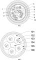
- the sheath includes a second water-blocking wrapping tape layer, a polyethylene heat insulation layer, a third water-blocking wrapping tape layer, an aluminum sheath, a polyethylene inner sheath, an armor layer, and a polyethylene outer sheath from inside to outside in turn.
- voids in the second water-blocking wrapping tape layer are filled with the third filler.
- the first filler is water-blocking gel
- the second filler is filling compound for optical fiber
- the third filler is cable sealant
- a composite cable for opto-electronic communication including a sheath, multiple optical cable units 1, multiple communication line units 3, and multiple power line units 2.
- the multiple optical cable units 1, the multiple power line units 2 and the multiple communication line units 3 are arranged inside the sheath.
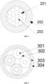
- FIG. 2 is a schematic diagram of a sectional structure of an optical cable unit according to the present disclosure.
- the first insulating layer 202 is formed by extruding polyethylene to wrap the outer circumferential surface of the first conductor 201, and is closely attached to the outer circumferential surface of the first conductor 201.
- the first conductor 201 is internally provided with a third filler 203.
- Table 1 Structure size and material list of power line unit 2 Item Unit Requirement The number of cores / 3 Conductor The number of copper wires piece 7 Diameter of each copper wire mm 0.52 Material / Annealed copper wire Insulation Thickness mm 1.0 Material / polyethylene Color / Red, white, blue Outer diameter mm 3.6 Table 2 Physical property table of power line unit 2 Name of insulating mixture Polyethylene Mechanical characteristics before ageing Tensile strength, Minimum (N/ mm 2 ) 12.5 Elongation at break, Minimum (%) 200 Mechanical characteristics after aging in air oven Treatment: Temperature (°C) 135 Tolerance (°C) ⁇ 2 Time (h) 168 Tensile strength: (a) Minimum value (N/ mm 2 ) - (b) Change, Maximum (%) ⁇ 25 Elongation at break: (a) Minimum value (N/ mm 2 ) - (b) Change, Maximum (%) ⁇ 25 Table 3 Electrical property table of power line unit 2 Serial number Item Unit Indicator 1 Maximum direct current resistance of
- the line group subunit includes a second conductor 301, and a second insulating layer 302.
- the second insulating layer 302 is arranged on and closely attached to an outer circumferential surface of the second conductor 301.
- the executive standard of the communication line unit 3 is:
- the electrical property of the outer sheath 10 conforms to the following requirements:
- the ground insulation resistance is 500 V
- DC is greater than 2000 M ⁇ km
- the electric withstand voltage strength is 15 kV
- the outer sheath is free of breakdown after DC for 2 min.
Landscapes
- Physics & Mathematics (AREA)
- General Physics & Mathematics (AREA)
- Optics & Photonics (AREA)
- Insulated Conductors (AREA)
- Communication Cables (AREA)
Applications Claiming Priority (1)
| Application Number | Priority Date | Filing Date | Title |
|---|---|---|---|
| CN202211598657.3A CN115862950A (zh) | 2022-12-12 | 2022-12-12 | 一种光电通信复合电缆 |
Publications (4)
| Publication Number | Publication Date |
|---|---|
| EP4398017A2 true EP4398017A2 (de) | 2024-07-10 |
| EP4398017A3 EP4398017A3 (de) | 2024-09-25 |
| EP4398017B1 EP4398017B1 (de) | 2025-08-13 |
| EP4398017C0 EP4398017C0 (de) | 2025-08-13 |
Family
ID=85672496
Family Applications (1)
| Application Number | Title | Priority Date | Filing Date |
|---|---|---|---|
| EP23215954.1A Active EP4398017B1 (de) | 2022-12-12 | 2023-12-12 | Verbundkabel für optoelektronische kommunikation |
Country Status (2)
| Country | Link |
|---|---|
| EP (1) | EP4398017B1 (de) |
| CN (1) | CN115862950A (de) |
Family Cites Families (8)
| Publication number | Priority date | Publication date | Assignee | Title |
|---|---|---|---|---|
| US5189718A (en) * | 1991-04-02 | 1993-02-23 | Siecor Corporation | Composite cable containing light waveguides and electrical conductors |
| CN102956326A (zh) * | 2012-11-08 | 2013-03-06 | 浙江汉维通信器材有限公司 | 全干式光电复合缆 |
| CN105336440A (zh) * | 2014-08-08 | 2016-02-17 | 上海朗达电缆(集团)有限公司 | 一种光纤复合中压电缆 |
| CN204010765U (zh) * | 2014-09-01 | 2014-12-10 | 北京鸿讯基业通信设备检测有限公司 | 环保抗压光电复合缆 |
| US10388429B1 (en) * | 2018-07-13 | 2019-08-20 | Superior Essex International LP | Hybrid cable with low density filling compound |
| CN110648785A (zh) * | 2019-10-29 | 2020-01-03 | 江苏亨通光电股份有限公司 | 一种新型室内无线分布系统用光电复合缆及其制备方法 |
| CN110993168A (zh) * | 2019-12-20 | 2020-04-10 | 宝胜科技创新股份有限公司 | 一种防水、耐腐蚀、防爆型水下探测用综合缆 |
| EP4154282A1 (de) * | 2020-05-18 | 2023-03-29 | CommScope Technologies LLC | Kabel zur verteilung von netzwerkleistung und -daten |
-
2022
- 2022-12-12 CN CN202211598657.3A patent/CN115862950A/zh active Pending
-
2023
- 2023-12-12 EP EP23215954.1A patent/EP4398017B1/de active Active
Also Published As
| Publication number | Publication date |
|---|---|
| CN115862950A (zh) | 2023-03-28 |
| EP4398017B1 (de) | 2025-08-13 |
| EP4398017A3 (de) | 2024-09-25 |
| EP4398017C0 (de) | 2025-08-13 |
Similar Documents
| Publication | Publication Date | Title |
|---|---|---|
| US9064618B2 (en) | Electrical cable with semi-conductive outer layer distinguishable from jacket | |
| WO2014081096A1 (en) | Fire resistant cable for medium or high voltage | |
| CN209912603U (zh) | 一种环保阻燃耐火中压电力电缆 | |
| CN103606405B (zh) | 35kV及以下新型环保型中压防火电缆及其生产方法 | |
| US11651870B2 (en) | Cable with semi-conducting outermost layer | |
| RU102833U1 (ru) | Кабель высокочастотный для цифровых сетей сельской связи (варианты) | |
| CN105632600A (zh) | 一种新型防火大容性电流抗电磁干扰中压电缆 | |
| CN217955536U (zh) | 一种基于交联聚乙烯的高效绝缘电力电缆 | |
| EP4398017A2 (de) | Verbundkabel für optoelektronische kommunikation | |
| CN211529645U (zh) | 一种超柔性矿物质防火电缆 | |
| CN221632272U (zh) | 一种10kV变压器引下线用防干扰架空绝缘电缆 | |
| CN219916777U (zh) | 一种复合异型导体和平滑铝护套一体化高压电缆 | |
| CN219143854U (zh) | 一种环保型中压阻燃耐火电缆 | |
| CN218886855U (zh) | 一种具有绝缘耐磨损功能的电子线 | |
| CN111210940A (zh) | 智能传感电缆 | |
| KR20200101857A (ko) | 전력케이블의 중간접속구조 | |
| CN218100792U (zh) | 低烟无卤阻燃防水型核电站用中压电力电缆 | |
| CN105529102A (zh) | 铝合金异型软导体金属套光电混合缆 | |
| CN217086221U (zh) | 一种防水、耐火细钢丝铠装电力电缆 | |
| CN109585071A (zh) | 一种耐雷电冲击防雷电缆线及制备方法 | |
| CN209912596U (zh) | 一种隔离型中压耐火电缆 | |
| CN217306160U (zh) | 一种耐磨耐高温高压线 | |
| CN220439258U (zh) | 一种聚丙烯绝缘中压耐火环保型电缆 | |
| CN218975190U (zh) | 一种导引检测故障中压电缆 | |
| CN219832260U (zh) | 一种光纤复合耐火中压电缆 |
Legal Events
| Date | Code | Title | Description |
|---|---|---|---|
| PUAI | Public reference made under article 153(3) epc to a published international application that has entered the european phase |
Free format text: ORIGINAL CODE: 0009012 |
|
| STAA | Information on the status of an ep patent application or granted ep patent |
Free format text: STATUS: REQUEST FOR EXAMINATION WAS MADE |
|
| 17P | Request for examination filed |
Effective date: 20231212 |
|
| AK | Designated contracting states |
Kind code of ref document: A2 Designated state(s): AL AT BE BG CH CY CZ DE DK EE ES FI FR GB GR HR HU IE IS IT LI LT LU LV MC ME MK MT NL NO PL PT RO RS SE SI SK SM TR |
|
| PUAL | Search report despatched |
Free format text: ORIGINAL CODE: 0009013 |
|
| AK | Designated contracting states |
Kind code of ref document: A3 Designated state(s): AL AT BE BG CH CY CZ DE DK EE ES FI FR GB GR HR HU IE IS IT LI LT LU LV MC ME MK MT NL NO PL PT RO RS SE SI SK SM TR |
|
| RIC1 | Information provided on ipc code assigned before grant |
Ipc: H01B 11/22 20060101ALI20240821BHEP Ipc: H01B 9/00 20060101ALI20240821BHEP Ipc: G02B 6/44 20060101AFI20240821BHEP |
|
| GRAP | Despatch of communication of intention to grant a patent |
Free format text: ORIGINAL CODE: EPIDOSNIGR1 |
|
| STAA | Information on the status of an ep patent application or granted ep patent |
Free format text: STATUS: GRANT OF PATENT IS INTENDED |
|
| INTG | Intention to grant announced |
Effective date: 20250521 |
|
| GRAS | Grant fee paid |
Free format text: ORIGINAL CODE: EPIDOSNIGR3 |
|
| GRAA | (expected) grant |
Free format text: ORIGINAL CODE: 0009210 |
|
| STAA | Information on the status of an ep patent application or granted ep patent |
Free format text: STATUS: THE PATENT HAS BEEN GRANTED |
|
| AK | Designated contracting states |
Kind code of ref document: B1 Designated state(s): AL AT BE BG CH CY CZ DE DK EE ES FI FR GB GR HR HU IE IS IT LI LT LU LV MC ME MK MT NL NO PL PT RO RS SE SI SK SM TR |
|
| REG | Reference to a national code |
Ref country code: GB Ref legal event code: FG4D |
|
| REG | Reference to a national code |
Ref country code: CH Ref legal event code: EP |
|
| REG | Reference to a national code |
Ref country code: DE Ref legal event code: R096 Ref document number: 602023005704 Country of ref document: DE |
|
| REG | Reference to a national code |
Ref country code: IE Ref legal event code: FG4D |
|
| U01 | Request for unitary effect filed |
Effective date: 20250908 |
|
| U07 | Unitary effect registered |
Designated state(s): AT BE BG DE DK EE FI FR IT LT LU LV MT NL PT RO SE SI Effective date: 20250912 |
|
| PG25 | Lapsed in a contracting state [announced via postgrant information from national office to epo] |
Ref country code: IS Free format text: LAPSE BECAUSE OF FAILURE TO SUBMIT A TRANSLATION OF THE DESCRIPTION OR TO PAY THE FEE WITHIN THE PRESCRIBED TIME-LIMIT Effective date: 20251213 |
|
| PG25 | Lapsed in a contracting state [announced via postgrant information from national office to epo] |
Ref country code: NO Free format text: LAPSE BECAUSE OF FAILURE TO SUBMIT A TRANSLATION OF THE DESCRIPTION OR TO PAY THE FEE WITHIN THE PRESCRIBED TIME-LIMIT Effective date: 20251113 |
|
| U20 | Renewal fee for the european patent with unitary effect paid |
Year of fee payment: 3 Effective date: 20251205 |
|
| PG25 | Lapsed in a contracting state [announced via postgrant information from national office to epo] |
Ref country code: HR Free format text: LAPSE BECAUSE OF FAILURE TO SUBMIT A TRANSLATION OF THE DESCRIPTION OR TO PAY THE FEE WITHIN THE PRESCRIBED TIME-LIMIT Effective date: 20250813 |
|
| PG25 | Lapsed in a contracting state [announced via postgrant information from national office to epo] |
Ref country code: GR Free format text: LAPSE BECAUSE OF FAILURE TO SUBMIT A TRANSLATION OF THE DESCRIPTION OR TO PAY THE FEE WITHIN THE PRESCRIBED TIME-LIMIT Effective date: 20251114 |
|
| PG25 | Lapsed in a contracting state [announced via postgrant information from national office to epo] |
Ref country code: PL Free format text: LAPSE BECAUSE OF FAILURE TO SUBMIT A TRANSLATION OF THE DESCRIPTION OR TO PAY THE FEE WITHIN THE PRESCRIBED TIME-LIMIT Effective date: 20250813 |
|
| PG25 | Lapsed in a contracting state [announced via postgrant information from national office to epo] |
Ref country code: RS Free format text: LAPSE BECAUSE OF FAILURE TO SUBMIT A TRANSLATION OF THE DESCRIPTION OR TO PAY THE FEE WITHIN THE PRESCRIBED TIME-LIMIT Effective date: 20251113 |
|
| PG25 | Lapsed in a contracting state [announced via postgrant information from national office to epo] |
Ref country code: ES Free format text: LAPSE BECAUSE OF FAILURE TO SUBMIT A TRANSLATION OF THE DESCRIPTION OR TO PAY THE FEE WITHIN THE PRESCRIBED TIME-LIMIT Effective date: 20250813 |
|
| PG25 | Lapsed in a contracting state [announced via postgrant information from national office to epo] |
Ref country code: SM Free format text: LAPSE BECAUSE OF FAILURE TO SUBMIT A TRANSLATION OF THE DESCRIPTION OR TO PAY THE FEE WITHIN THE PRESCRIBED TIME-LIMIT Effective date: 20250813 |
|
| PG25 | Lapsed in a contracting state [announced via postgrant information from national office to epo] |
Ref country code: CZ Free format text: LAPSE BECAUSE OF FAILURE TO SUBMIT A TRANSLATION OF THE DESCRIPTION OR TO PAY THE FEE WITHIN THE PRESCRIBED TIME-LIMIT Effective date: 20250813 |
|
| PG25 | Lapsed in a contracting state [announced via postgrant information from national office to epo] |
Ref country code: SK Free format text: LAPSE BECAUSE OF FAILURE TO SUBMIT A TRANSLATION OF THE DESCRIPTION OR TO PAY THE FEE WITHIN THE PRESCRIBED TIME-LIMIT Effective date: 20250813 |