EP4397498A1 - Light irradiation device - Google Patents
Light irradiation device Download PDFInfo
- Publication number
- EP4397498A1 EP4397498A1 EP23215865.9A EP23215865A EP4397498A1 EP 4397498 A1 EP4397498 A1 EP 4397498A1 EP 23215865 A EP23215865 A EP 23215865A EP 4397498 A1 EP4397498 A1 EP 4397498A1
- Authority
- EP
- European Patent Office
- Prior art keywords
- plate
- shaped portion
- wall portions
- light irradiation
- light
- Prior art date
- Legal status (The legal status is an assumption and is not a legal conclusion. Google has not performed a legal analysis and makes no representation as to the accuracy of the status listed.)
- Granted
Links
Images




Classifications
-
- B—PERFORMING OPERATIONS; TRANSPORTING
- B41—PRINTING; LINING MACHINES; TYPEWRITERS; STAMPS
- B41J—TYPEWRITERS; SELECTIVE PRINTING MECHANISMS, i.e. MECHANISMS PRINTING OTHERWISE THAN FROM A FORME; CORRECTION OF TYPOGRAPHICAL ERRORS
- B41J11/00—Devices or arrangements of selective printing mechanisms, e.g. ink-jet printers or thermal printers, for supporting or handling copy material in sheet or web form
- B41J11/0015—Devices or arrangements of selective printing mechanisms, e.g. ink-jet printers or thermal printers, for supporting or handling copy material in sheet or web form for treating before, during or after printing or for uniform coating or laminating the copy material before or after printing
- B41J11/002—Curing or drying the ink on the copy materials, e.g. by heating or irradiating
- B41J11/0021—Curing or drying the ink on the copy materials, e.g. by heating or irradiating using irradiation
- B41J11/00214—Curing or drying the ink on the copy materials, e.g. by heating or irradiating using irradiation using UV radiation
-
- F—MECHANICAL ENGINEERING; LIGHTING; HEATING; WEAPONS; BLASTING
- F21—LIGHTING
- F21V—FUNCTIONAL FEATURES OR DETAILS OF LIGHTING DEVICES OR SYSTEMS THEREOF; STRUCTURAL COMBINATIONS OF LIGHTING DEVICES WITH OTHER ARTICLES, NOT OTHERWISE PROVIDED FOR
- F21V29/00—Protecting lighting devices from thermal damage; Cooling or heating arrangements specially adapted for lighting devices or systems
- F21V29/50—Cooling arrangements
- F21V29/56—Cooling arrangements using liquid coolants
- F21V29/59—Cooling arrangements using liquid coolants with forced flow of the coolant
-
- B—PERFORMING OPERATIONS; TRANSPORTING
- B41—PRINTING; LINING MACHINES; TYPEWRITERS; STAMPS
- B41J—TYPEWRITERS; SELECTIVE PRINTING MECHANISMS, i.e. MECHANISMS PRINTING OTHERWISE THAN FROM A FORME; CORRECTION OF TYPOGRAPHICAL ERRORS
- B41J11/00—Devices or arrangements of selective printing mechanisms, e.g. ink-jet printers or thermal printers, for supporting or handling copy material in sheet or web form
- B41J11/0015—Devices or arrangements of selective printing mechanisms, e.g. ink-jet printers or thermal printers, for supporting or handling copy material in sheet or web form for treating before, during or after printing or for uniform coating or laminating the copy material before or after printing
- B41J11/002—Curing or drying the ink on the copy materials, e.g. by heating or irradiating
- B41J11/0021—Curing or drying the ink on the copy materials, e.g. by heating or irradiating using irradiation
- B41J11/00218—Constructional details of the irradiation means, e.g. radiation source attached to reciprocating print head assembly or shutter means provided on the radiation source
-
- B—PERFORMING OPERATIONS; TRANSPORTING
- B41—PRINTING; LINING MACHINES; TYPEWRITERS; STAMPS
- B41J—TYPEWRITERS; SELECTIVE PRINTING MECHANISMS, i.e. MECHANISMS PRINTING OTHERWISE THAN FROM A FORME; CORRECTION OF TYPOGRAPHICAL ERRORS
- B41J29/00—Details of, or accessories for, typewriters or selective printing mechanisms not otherwise provided for
- B41J29/377—Cooling or ventilating arrangements
-
- F—MECHANICAL ENGINEERING; LIGHTING; HEATING; WEAPONS; BLASTING
- F21—LIGHTING
- F21V—FUNCTIONAL FEATURES OR DETAILS OF LIGHTING DEVICES OR SYSTEMS THEREOF; STRUCTURAL COMBINATIONS OF LIGHTING DEVICES WITH OTHER ARTICLES, NOT OTHERWISE PROVIDED FOR
- F21V29/00—Protecting lighting devices from thermal damage; Cooling or heating arrangements specially adapted for lighting devices or systems
- F21V29/50—Cooling arrangements
- F21V29/502—Cooling arrangements characterised by the adaptation for cooling of specific components
- F21V29/503—Cooling arrangements characterised by the adaptation for cooling of specific components of light sources
-
- F—MECHANICAL ENGINEERING; LIGHTING; HEATING; WEAPONS; BLASTING
- F21—LIGHTING
- F21V—FUNCTIONAL FEATURES OR DETAILS OF LIGHTING DEVICES OR SYSTEMS THEREOF; STRUCTURAL COMBINATIONS OF LIGHTING DEVICES WITH OTHER ARTICLES, NOT OTHERWISE PROVIDED FOR
- F21V29/00—Protecting lighting devices from thermal damage; Cooling or heating arrangements specially adapted for lighting devices or systems
- F21V29/50—Cooling arrangements
- F21V29/70—Cooling arrangements characterised by passive heat-dissipating elements, e.g. heat-sinks
- F21V29/74—Cooling arrangements characterised by passive heat-dissipating elements, e.g. heat-sinks with fins or blades
- F21V29/76—Cooling arrangements characterised by passive heat-dissipating elements, e.g. heat-sinks with fins or blades with essentially identical parallel planar fins or blades, e.g. with comb-like cross-section
- F21V29/763—Cooling arrangements characterised by passive heat-dissipating elements, e.g. heat-sinks with fins or blades with essentially identical parallel planar fins or blades, e.g. with comb-like cross-section the planes containing the fins or blades having the direction of the light emitting axis
-
- F—MECHANICAL ENGINEERING; LIGHTING; HEATING; WEAPONS; BLASTING
- F21—LIGHTING
- F21Y—INDEXING SCHEME ASSOCIATED WITH SUBCLASSES F21K, F21L, F21S and F21V, RELATING TO THE FORM OR THE KIND OF THE LIGHT SOURCES OR OF THE COLOUR OF THE LIGHT EMITTED
- F21Y2105/00—Planar light sources
- F21Y2105/10—Planar light sources comprising a two-dimensional [2D] array of point-like light-generating elements
- F21Y2105/12—Planar light sources comprising a two-dimensional [2D] array of point-like light-generating elements characterised by the geometrical disposition of the light-generating elements, e.g. arranging light-generating elements in differing patterns or densities
-
- F—MECHANICAL ENGINEERING; LIGHTING; HEATING; WEAPONS; BLASTING
- F21—LIGHTING
- F21Y—INDEXING SCHEME ASSOCIATED WITH SUBCLASSES F21K, F21L, F21S and F21V, RELATING TO THE FORM OR THE KIND OF THE LIGHT SOURCES OR OF THE COLOUR OF THE LIGHT EMITTED
- F21Y2105/00—Planar light sources
- F21Y2105/10—Planar light sources comprising a two-dimensional [2D] array of point-like light-generating elements
- F21Y2105/14—Planar light sources comprising a two-dimensional [2D] array of point-like light-generating elements characterised by the overall shape of the two-dimensional [2D] array
- F21Y2105/16—Planar light sources comprising a two-dimensional [2D] array of point-like light-generating elements characterised by the overall shape of the two-dimensional [2D] array square or rectangular, e.g. for light panels
Definitions
- a light irradiation device 1 includes a light irradiation unit 2, a power supply unit 3, and a chiller 4.
- the light irradiation unit 2 includes a light irradiation section 10 and a cooling section 20.
- the light irradiation section 10 includes a plurality of light-emitting elements 11 which are two-dimensionally arranged along a plane perpendicular to a Z-direction (a first direction).
- the cooling section 20 has an inlet port 20a and an outlet port 20b. The cooling section 20 cools down the plurality of light-emitting elements 11 by circulating a coolant from the inlet port 20a to the outlet port 20b.
- Each of the light-emitting elements 11 is disposed on each of the mounting patterns 16 through a joining layer 17.
- the joining layer 17 is a solder layer, and joins an anode of the light-emitting element 11 and the mounting pattern 16.
- a wire 18 is laid between a cathode of a light-emitting element 11 on the first electrode pattern 14 side and a mounting pattern 16 on which a light-emitting element 11 on the second electrode pattern 15 side is disposed.
- a wire 18 is laid between a cathode of the light-emitting element 11 and the second electrode pattern 15.
- the power supply unit 3 (refer to FIG. 1 ) supplies electric power to the plurality of light-emitting elements 11 through the first electrode pattern 14 and the second electrode pattern 15 and turns on the plurality of light-emitting elements 11.
- the joining layer 17 may be a layer formed from a metal joining material such as a brazing material without limitation to the solder layer.
- each of the light-emitting elements 11 may be mounted on each of the mounting patterns 16 by a joining method such as bump joining.
- the cooling section 20 includes a first plate-shaped portion 21, a second plate-shaped portion 22, a plurality of first wall portions 23, a plurality of second wall portions 24, and a frame portion 25.
- the first plate-shaped portion 21, the second plate-shaped portion 22, the plurality of first wall portions 23, the plurality of second wall portions 24, and the frame portion 25 are formed from a material (for example, copper, aluminum, or the like) excellent in thermal conductivity and workability in a solid type.
- a heat conductive member such as thermal grease may be disposed between the first plate-shaped portion 21 and the bases 12. Note that, in FIG. 4 , a plurality of first protrusions 27 and a plurality of second protrusions 29 to be described later are hatched from the viewpoint of visibility.
- Each of the first wall portions 23 extends between the first plate-shaped portion 21 and the second plate-shaped portion 22 in the X-direction.
- the plurality of first wall portions 23 are arranged between the first plate-shaped portion 21 and the second plate-shaped portion 22 in the Y-direction.
- Each of the second wall portions 24 extends between the first plate-shaped portion 21 and the second plate-shaped portion 22 in the X-direction.
- the plurality of second wall portions 24 are arranged between the first plate-shaped portion 21 and the second plate-shaped portion 22 in the Y-direction.
- the first wall portions 23 and the second wall portions 24 are alternately disposed in a state of being spaced apart from each other.
- the inlet port 20a is disposed on one side in the Y-direction with respect to the plurality of first wall portions 23 and the plurality of second wall portions 24.
- the outlet port 20b is disposed on the other side in the Y-direction with respect to the plurality of first wall portions 23 and the plurality of second wall portions 24.
- the inlet port 20a and the outlet port 20b are formed in the second plate-shaped portion 22 to face the first plate-shaped portion 21 in the Z-direction.
- the inlet port 20a and the outlet port 20b are arranged in the Y-direction at the center of the frame portion 25 in the X-direction when viewed in the Z-direction.
- Each of the first wall portions 23 has a plurality of first passage portions 23a through which a coolant passes.
- Each of the second wall portions 24 has a plurality of second passage portions 24a through which the coolant passes.
- the plurality of first passage portions 23a are arranged in the X-direction and are biased to the second plate-shaped portion 22 side in the Z-direction. That is, the center of each of the first passage portions 23a in the Z-direction is located on the second plate-shaped portion 22 side with respect to the center of each of the first wall portions 23 in the Z-direction.
- the plurality of second passage portions 24a are arranged in the X-direction and are biased to the first plate-shaped portion 21 side in the Z-direction. That is, the center of each of the second passage portions 24a in the Z-direction is located on the first plate-shaped portion 21 side with respect to the center of each of the second wall portions 24 in the Z-direction.
- each of the first wall portions 23 includes a first main body portion 26 and the plurality of first protrusions 27.
- the first main body portion 26 extends in the X-direction.
- the plurality of first protrusions 27 are arranged in the X-direction.
- Each of the first protrusions 27 protrudes from the first main body portion 26 to the second plate-shaped portion 22 side, and is formed in a square column shape.
- Each of the first passage portions 23a is a region between a pair of adjacent first protrusions 27.
- the first main body portion 26 and the plurality of first protrusions 27 are formed integrally with the first plate-shaped portion 21.
- the first main body portion 26 is thermally connected to the first plate-shaped portion 21.
- Each of the first protrusions 27 is joined to the second plate-shaped portion 22 with a brazing material 31.
- the brazing material 31 is disposed between a top surface 27a of each of the first protrusions 27 and a surface 22a of the second plate-shaped portion 22 on the first plate-shaped portion 21 side.
- each of the first protrusions 27 is thermally connected to the second plate-shaped portion 22. That is, each of the first wall portions 23 is thermally connected to each of the first plate-shaped portion 21 and the second plate-shaped portion 22.
- first passage portions 23a located at both ends among the plurality of first passage portions 23a arranged in the X-direction face the frame portion 25. That is, in each of the first passage portions 23a located at both ends, an inner surface of the frame portion 25 is exposed to the first passage portion 23a.
- each of the second wall portions 24 includes a second main body portion 28, and the plurality of second protrusions 29.
- the second main body portion 28 extends in the X-direction.
- the plurality of second protrusions 29 are arranged in the X-direction.
- Each of the second protrusions 29 protrudes from the second main body portion 28 toward the first plate-shaped portion 21 side, and is formed in a square column shape.
- Each of the second passage portions 24a is a region between a pair of adjacent second protrusions 29.
- the second main body portion 28 and the plurality of second protrusions 29 are formed integrally with the second plate-shaped portion 22.
- the second main body portion 28 is thermally connected to the second plate-shaped portion 22.
- Each of the second protrusions 29 is joined to the first plate-shaped portion 21 with the brazing material 31.
- the brazing material 31 is disposed between a top surface 29a of each of the second protrusions 29, and a surface 21a of the first plate-shaped portion 21 on the second plate-shaped portion 22 side.
- each of the second protrusions 29 is thermally connected to the first plate-shaped portion 21. That is, each of the second wall portions 24 is thermally connected to each of the first plate-shaped portion 21 and the second plate-shaped portion 22.
- second passage portions 24a located at both ends among the plurality of second passage portions 24a arranged in the X-direction is face the frame portion 25. That is, in each of the second passage portions 24a located at both ends, an inner surface of the frame portion 25 is exposed to the second passage portions 24a.
- the frame portion 25 is formed integrally with the first plate-shaped portion 21.
- the frame portion 25 is joined to the second plate-shaped portion 22 with the brazing material 31.
- the brazing material 31 is disposed between a surface 25a of the frame portion 25 on the second plate-shaped portion 22 side, and the surface 22a of the second plate-shaped portion 22. According to this, the frame portion 25 is thermally connected to each of the first plate-shaped portion 21 and the second plate-shaped portion 22. Note that, both ends of each of a plurality of the first main body portions 26 and both ends of each of a plurality of the second main body portions 28 are connected to the frame portion 25.
- the first passage portions 23a and the second passage portions 24a are linearly and alternately arranged along a line parallel to the Y-direction when viewed in the Z-direction.
- An arrangement pitch of the plurality of first passage portions 23a in the X-direction, and an arrangement pitch of the plurality of second passage portions 24a in the X-direction are substantially equal to each other.
- the first passage portions 23a and the second passage portions 24a are alternately arranged in a zigzag shape along a line parallel to the Y-direction. As illustrated in FIG. 4 and FIG.
- the inlet port 20a is formed in the second plate-shaped portion 22, and among the plurality of first wall portions 23 and the plurality of second wall portions 24, a wall portion closest to the inlet port 20a in the Y-direction is one of the first wall portions 23.
- the region R1 where the plurality of light-emitting elements 11 are disposed is included in a region R2 where the plurality of first wall portions 23 and the plurality of second wall portions 24 are disposed at least in the Y-direction.
- some light-emitting elements 11 among the plurality of light-emitting elements 11 overlap the frame portion 25.
- an outer edge of the first plate-shaped portion 21, an outer edge of the second plate-shaped portion 22, and an outer edge of the frame portion 25 match each other.
- a corrosion prevention layer such as an Ni-plated film is provided on a surface exposed to the coolant.
- thermal conductivity of a material constituting the brazing material 31 is higher than thermal conductivity of materials constituting the first plate-shaped portion 21, the second plate-shaped portion 22, the plurality of first wall portions 23, the plurality of second wall portions 24, and the frame portion 25.
- the coolant is circulated and supplied to the cooling section 20 by the chiller 4 while the plurality of light-emitting elements 11 are turned on by supplying electric power from the power supply unit 3 to the light irradiation section 10.
- the coolant flows in from the inlet port 20a, passes through the plurality of first passage portions 23a and the plurality of second passage portions 24a, and flows out from the outlet port 20b.
- a flow direction of the coolant can be changed in a zigzag shape in the Z-direction.
- Heat generated by the plurality of light-emitting elements 11 is transferred to the first plate-shaped portion 21 through the base 12, and is transferred to the coolant while moving from the first plate-shaped portion 21 side to the second plate-shaped portion 22 side through each of the first wall portions 23, each of the second wall portions 24, and the frame portion 25. In this manner, heat generated by the plurality of light-emitting elements 11 is removed.
- the first wall portions 23 and the second wall portions 24 are alternately disposed in a state of being spaced apart from each other between the first plate-shaped portion 21 and the second plate-shaped portion 22 and on an inner side of the frame portion 25.
- the plurality of first passage portions 23a are biased to the second plate-shaped portion 22 side
- the plurality of second passage portions 24a are biased to the first plate-shaped portion 21 side.
- each of the first wall portions 23, each of the second wall portions 24, and the frame portion 25 are thermally connected to each of the first plate-shaped portion 21 and the second plate-shaped portion 22. According to this, heat generated by the plurality of light-emitting elements 11 is easily transferred from the first plate-shaped portion 21 side to the second plate-shaped portion 22 side through each of the first wall portions 23, each of the second wall portions 24, and the frame portion 25. As a result, the cooling efficiency by the cooling section 20 is improved. As described above, according to the light irradiation device 1, it is possible to uniformly cool down the plurality of light-emitting elements 11.
- each of the first wall portions 23 includes the first main body portion 26 that is thermally connected to the first plate-shaped portion 21, and the plurality of first protrusions 27 which are thermally connected to the second plate-shaped portion 22.
- Each of the first passage portions 23a is a region between a pair of adjacent first protrusions 27.
- each of the second wall portions 24 includes the second main body portion 28 that is thermally connected to the second plate-shaped portion 22, and the plurality of second protrusions 29 which are thermally connected to the first plate-shaped portion 21, and each of the second passage portions 24a is a region between a pair of adjacent second protrusions 29.
- the first main body portion 26 and the plurality of first protrusions 27 are formed integrally with the first plate-shaped portion 21, and each of the first protrusion 27 is joined to the second plate-shaped portion 22 with the brazing material 31.
- the second main body portion 28 and the plurality of second protrusions 29 are formed integrally with the second plate-shaped portion 22, and each of the second protrusions 29 is joined to the first plate-shaped portion 21 with the brazing material 31.
- the frame portion 25 is formed integrally with the first plate-shaped portion 21, and is joined to the second plate-shaped portion 22 with the brazing material 31.
- each of the first wall portions 23, each of the second wall portions 24, and the frame portion 25 are thermally connected to each of the first plate-shaped portion 21 and the second plate-shaped portion 22 with a simple structure.
- each of the first protrusions 27 and each of the second protrusions 29 are formed in a square column shape. According to this, since turbulence is likely to occur in a flow of the coolant, it is possible to improve the cooling efficiency by the cooling section 20. In addition, it is possible to easily manufacture the cooling section 20.
- the thickness of the second plate-shaped portion 22 is larger than the thickness of the first plate-shaped portion 21. According to this, since heat capacity of the second plate-shaped portion 22 becomes larger than heat capacity of the first plate-shaped portion 21, heat generated by the plurality of light-emitting elements 11 can be efficiently and reliably transferred from the first plate-shaped portion 21 to the second plate-shaped portion 22.
- the inlet port 20a is formed in the second plate-shaped portion 22 to face the first plate-shaped portion 21 in the Z-direction. According to this, since the coolant flowing in from the inlet port 20a flows so as to collide with the first plate-shaped portion 21, it is possible to cool down the plurality of light-emitting elements 1 1with further efficiency.
- the inlet port 20a is formed in the second plate-shaped portion 22, and among the plurality of first wall portions 23 and the plurality of second wall portions 24, a wall portion closest to the inlet port 20a in the Y-direction is one of the first wall portions 23. According to this, when the coolant flowing in from the inlet port 20a formed in the second plate-shaped portion 22 heads toward the plurality of first passage portions 23a provided in the first wall portion 23 closest to the inlet port 20a, since a flow direction of the coolant can be greatly changed, and a flow velocity of the coolant becomes uniform in the X-direction, it is possible to more uniformly cool down the plurality of light-emitting elements 11.
- the inlet port 20a may not be formed in the second plate-shaped portion 22 so as to face the first plate-shaped portion 21 in the Z-direction.
- the inlet port 20a may be formed in the frame portion 25, or may be formed in the first plate-shaped portion 21 so as to face the second plate-shaped portion 22 in the Z-direction.
- the outlet port 20b may not be formed in the second plate-shaped portion 22 so as to face the first plate-shaped portion 21 in the Z-direction.
- the outlet port 20b may be formed in the frame portion 25, or may be formed in the first plate-shaped portion 21 so as to face the second plate-shaped portion 22 in the Z-direction.
- the cooling section 20 may include a plurality of the inlet ports 20a.
- the cooling section 20 may include a plurality of the outlet port 20b.
- the thickness of the second plate-shaped portion 22 may be equal to the thickness of the first plate-shaped portion 21, or may be smaller than the thickness of the first plate-shaped portion 21.
- the plurality of first passage portions 23a may not be the region between the pair of adjacent first protrusions 27 as long as the plurality of first passage portions 23a are arranged in the X-direction and are biased to the second plate-shaped portion 22 side in the Z-direction.
- the plurality of second passage portions 24a may not be the region between the pair of adjacent second protrusions 29 as long as the plurality of second passage portions 24a are arranged in the X-direction and are biased to the first plate-shaped portion 21 side in the Z-direction.
- Each of the first wall portions 23 may be formed separately from the first plate-shaped portion 21 or may be formed integrally with the second plate-shaped portion 22 as long as the first wall portion 23 is thermally connected to each of the first plate-shaped portion 21 and the second plate-shaped portion 22.
- each of the second wall portions 24 may be formed integrally with the first plate-shaped portion 21 or may be formed separately from the second plate-shaped portion 22 as long as the second wall portion 24 is thermally connected to each of the first plate-shaped portion 21 and the second plate-shaped portion 22.
- the frame portion 25 may be formed separately from the first plate-shaped portion 21 or may be formed integrally with the second plate-shaped portion 22 as long as the frame portion 25 is thermally connected to each of the first plate-shaped portion 21 and the second plate-shaped portion 22.
- the frame portion 25 may be formed integrally with the second plate-shaped portion 22, and may be joined to the first plate-shaped portion 21 with the brazing material 31.
- the region R1 where the plurality of light-emitting elements 11 are disposed may be included in the region R2 where the plurality of first wall portions 23 and the plurality of second wall portions 24 are disposed not only in the Y-direction but also in the X-direction. That is, the entirety of the region R1 may be included in the region R2 when viewed in the Z-direction.
- a corner of a side surface of each of the first protrusions 27, and a corner of a side surface of each of the second protrusions 29 may be chamfered in a round shape.
- each of the first protrusions 27 and each of the second protrusions 29 may be formed in a circular column shape. According to the configurations, the coolant can be smoothly circulated in each of the first passage portions 23a and each of the second passage portions 24a.
- each of the first passage portions 23a and each of the second passage portions 24a may be alternately arranged in a zigzag shape along a line parallel to the Y-direction. According to this, since a flow direction of the coolant can be changed in a zigzag shape not only in the Z-direction but also the X-direction, a contact area with the coolant in the cooling section 20 increases, and turbulence is more likely to occur in the flow of the coolant. As a result, the cooling efficiency by the cooling section 20 can be more improved.
- the arrangement pitch of the plurality of first passage portions 23a in the X-direction, and the arrangement pitch of the plurality of second passage portions 24a in the X-direction may not be substantially equal to each other.
- the arrangement pitch of the plurality of first passage portions 23a in the X-direction, and the arrangement pitch of the plurality of second passage portions 24a in the X-direction may be sparser as approaching the inlet port 20a and the outlet port 20b (in other words, may be denser as being spaced apart from the inlet port 20a and the outlet port 20b). In this case, the plurality of light-emitting elements 11 can be more uniformly cooled.
- the cooling section 20 may include a plurality of radiation fins 32.
- the plurality of radiation fins 32 are provided on a surface 22b on an opposite side of the second plate-shaped portion 22 from the first plate-shaped portion 21. According to this, since heat dissipation in the second plate-shaped portion 22 is improved, it is possible to efficiently and reliably transfer heat generated by the plurality of light-emitting elements 11 from the first plate-shaped portion 21 side to the second plate-shaped portion 22 side.
- a wall portion closest to the inlet port 20a in the Y-direction among the plurality of first wall portions 23 and the plurality of second wall portions 24 may be one of the second wall portions 24.
- the light irradiation device is [1] "A light irradiation device including: a light irradiation section including a plurality of light-emitting elements being two-dimensionally arranged along a plane perpendicular to a first direction; and a cooling section including an inlet port and an outlet port and configured to cool down the plurality of light-emitting elements by circulating a coolant from the inlet port to the outlet port.
- the cooling section includes a first plate-shaped portion being thermally connected to the plurality of light-emitting elements, a second plate-shaped portion facing the first plate-shaped portion in the first direction, a plurality of first wall portions each extending between the first plate-shaped portion and the second plate-shaped portion in a second direction perpendicular to the first direction, and arranged in a third direction perpendicular to both the first direction and the second direction, a plurality of second wall portions each extending between the first plate-shaped portion and the second plate-shaped portion in the second direction, and arranged in the third direction, and a frame portion surrounding the plurality of first wall portions and the plurality of second wall portions between the first plate-shaped portion and the second plate-shaped portion.
- the inlet port is disposed on one side in the third direction with respect to the plurality of first wall portions and the plurality of second wall portions
- the outlet port is disposed on the other side in the third direction with respect to the plurality of first wall portions and the plurality of second wall portions
- each of the plurality of first wall portions and each of the plurality of second wall portions are alternately disposed in a state of being spaced apart from each other
- each of the plurality of first wall portions is thermally connected to each of the first plate-shaped portion and the second plate-shaped portion
- each of the plurality of second wall portions is thermally connected to each of the first plate-shaped portion and the second plate-shaped portion
- the frame portion is thermally connected to each of the first plate-shaped portion and the second plate-shaped portion
- each of the plurality of first wall portions includes a plurality of first passage portions through which the coolant passes
- each of the plurality of second wall portions includes a plurality of second passage portions through which the coolant passes
- the plurality of first passage portions are
- each of the plurality of first wall portions and each of the plurality of second wall portions are alternately disposed in a state of being spaced apart from each other between the first plate-shaped portion and the second plate-shaped portion and on an inner side of the frame portion, in each of the plurality of first wall portions, the plurality of first passage portions are biased to the second plate-shaped portion side, and in each of the plurality of second wall portions, the plurality of second passage portions are biased to the first plate-shaped portion side.
- each of the plurality of first wall portions, each of the plurality of second wall portions, and the frame portion are thermally connected to each of the first plate-shaped portion and the second plate-shaped portion.
- heat generated by the plurality of light-emitting elements is easily transferred from the first plate-shaped portion side to the second plate-shaped portion side through each of the plurality of first wall portions, each of the plurality of second wall portions, and the frame portion.
- the cooling efficiency by the cooling section is improved.
- according to the light irradiation device described in [1] it is possible to uniformly cool down the plurality of light-emitting elements.
- the light irradiation device may be [3] "The light irradiation device according to [2], wherein the first main body portion and the plurality of first protrusions are formed integrally with the first plate-shaped portion, each of the plurality of first protrusions is joined to the second plate-shaped portion with a brazing material, the second main body portion and the plurality of second protrusions are formed integrally with the second plate-shaped portion, each of the plurality of second protrusions is joined to the first plate-shaped portion with a brazing material, the frame portion is formed integrally with one of the first plate-shaped portion and the second plate-shaped portion, and the frame portion is joined to the other of the first plate-shaped portion and the second plate-shaped portion with a brazing material".
Landscapes
- Engineering & Computer Science (AREA)
- General Engineering & Computer Science (AREA)
- Health & Medical Sciences (AREA)
- General Health & Medical Sciences (AREA)
- Toxicology (AREA)
- Cooling Or The Like Of Semiconductors Or Solid State Devices (AREA)
- Led Device Packages (AREA)
- Ink Jet (AREA)
Abstract
Description
- The present disclosure relates to a light irradiation device.
- There is known a light irradiation device including a light irradiation section that includes a plurality of light-emitting elements which are two-dimensionally arranged along a plane perpendicular to a predetermined direction, and a cooling section that cools down the plurality of light-emitting elements by circulating a coolant. In the light irradiation device, a flow passage of the coolant in the cooling section meanders along a plane perpendicular to a predetermined direction (for example, refer to
Japanese Unexamined Patent Publication No. 2013-229519 - In the light irradiation device as described above, since a temperature of the coolant rises as going toward a downward side of a flow passage, it is difficult to uniformly cool down a plurality of light-emitting elements. For example, in a case where the light irradiation device as described above is used to dry ink on printed matters, it is very important to uniformly cool down the plurality of light-emitting elements in order to make illuminance of the light-emitting elements uniform.
- An object of the present disclosure is to provide a light irradiation device capable of uniformly cooling down a plurality of light-emitting elements.
- According to an aspect of the present disclosure, there is provided a light irradiation device including: a light irradiation section including a plurality of light-emitting elements which are two-dimensionally arranged along a plane perpendicular to a first direction; and a cooling section that includes an inlet port and an outlet port and cools down the plurality of light-emitting elements by circulating a coolant from the inlet port to the outlet port. The cooling section includes a first plate-shaped portion that is thermally connected to the plurality of light-emitting elements, a second plate-shaped portion that faces the first plate-shaped portion in the first direction, a plurality of first wall portions which extend between the first plate-shaped portion and the second plate-shaped portion in a second direction perpendicular to the first direction, and are arranged in a third direction perpendicular to both the first direction and the second direction, a plurality of second wall portions which extend between the first plate-shaped portion and the second plate-shaped portion in the second direction, and are arranged in the third direction, and a frame portion that surrounds the plurality of first wall portions and the plurality of second wall portions between the first plate-shaped portion and the second plate-shaped portion. The inlet port is disposed on one side in the third direction with respect to the plurality of first wall portions and the plurality of second wall portions, the outlet port is disposed on the other side in the third direction with respect to the plurality of first wall portions and the plurality of second wall portions, each of the plurality of first wall portions and each of the plurality of second wall portions are alternately disposed in a state of being spaced apart from each other, each of the plurality of first wall portions is thermally connected to each of the first plate-shaped portion and the second plate-shaped portion, each of the plurality of second wall portions is thermally connected to each of the first plate-shaped portion and the second plate-shaped portion, the frame portion is thermally connected to each of the first plate-shaped portion and the second plate-shaped portion, each of the plurality of first wall portions includes a plurality of first passage portions through which the coolant passes, each of the plurality of second wall portions includes a plurality of second passage portions through which the coolant passes, the plurality of first passage portions are arranged in the second direction and are biased to the second plate-shaped portion side in the first direction, and the plurality of second passage portions arranged in the second direction and are biased to the first plate-shaped portion side in the first direction.
-
-
FIG. 1 is a configuration diagram of a light irradiation device of an embodiment. -
FIG. 2 is a bottom view of a light irradiation section shown inFIG. 1 . -
FIG. 3 is a cross-sectional view of the light irradiation section along a line III-III shown inFIG. 2 . -
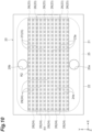
FIG. 4 is a plan view of a cooling section shown inFIG. 1 . -
FIG. 5 is a cross-sectional view of the cooling section along a plane perpendicular to an X-direction shown inFIG. 4 . -
FIG. 6 is a cross-section view of a part of the cooling section along the plane perpendicular to the X-direction shown inFIG. 4 . -
FIG. 7 is a cross-sectional view of a part of a first wall portion along a plane perpendicular to a Y-direction shown inFIG. 4 . -
FIG. 8 is a cross-sectional view of a part of a second wall portion along the plane perpendicular to the Y-direction shown inFIG. 4 . -
FIG. 9 is a plan view of a cooling section of a modification example. -
FIG. 10 is a plan view of a cooling section of a modification example. -
FIG. 11 is a plan view of a cooling section of a modification example. -
FIG. 12 is a cross-sectional view of a cooling section of a modification example along a plane perpendicular to the X-direction. - Hereinafter, an embodiment of the present disclosure will be described in detail with reference to the drawings. Note that, in the drawings, the same reference numeral will be given to the same or equivalent portions, and redundant description will be omitted.
- As illustrated in
FIG. 1 , alight irradiation device 1 includes alight irradiation unit 2, apower supply unit 3, and achiller 4. Thelight irradiation unit 2 includes alight irradiation section 10 and acooling section 20. Thelight irradiation section 10 includes a plurality of light-emittingelements 11 which are two-dimensionally arranged along a plane perpendicular to a Z-direction (a first direction). Thecooling section 20 has aninlet port 20a and anoutlet port 20b. Thecooling section 20 cools down the plurality of light-emittingelements 11 by circulating a coolant from theinlet port 20a to theoutlet port 20b. Thepower supply unit 3 is electrically connected to thelight irradiation section 10. Thepower supply unit 3 supplies electric power to thelight irradiation section 10. Thechiller 4 is connected to theinlet port 20a of thecooling section 20 through apipeline 5, and is connected to theoutlet port 20b of thecooling section 20 through apipeline 6. Thechiller 4 circulates and supplies the coolant to thecooling section 20 while cooling down the coolant. As an example, with respect to printed matters conveyed along a plane perpendicular to the Z-direction, thelight irradiation device 1 is used to dry ink on the printed matters by irradiating the printed matters with ultraviolet rays emitted from the plurality of light-emittingelements 11. - As illustrated in
FIG. 2 , in thelight irradiation section 10, the plurality of light-emittingelements 11 are supported by a plurality ofbases 12. For example, each of the light-emittingelements 11 is an LED element that emits ultraviolet rays. The plurality ofbases 12 are arranged in an X-direction (a second direction perpendicular to the first direction). For example, each of thebases 12 is formed in a rectangular plate shape in which the Z-direction is set as a thickness direction. Each of thebases 12 is formed from a material (for example, copper, aluminum, aluminum nitride, or the like) having excellent thermal conductivity. In each of thebases 12, for example, the plurality of light-emittingelements 11 are arranged in a matrix shape in which the X-direction is set as a row direction, and a Y-direction (a third direction perpendicular to both the first direction and the second direction) is set as a column direction. A region R1 where the plurality of light-emittingelements 11 are arranged has, for example, a rectangular shape in which the X-direction is set as a long side direction. - An example of a configuration of the
light irradiation section 10 will be described in more detail.FIG. 3 is a cross-sectional view of thelight irradiation section 10 along a line III-III shown inFIG. 2 . As illustrated inFIG. 3 , aninsulation layer 13 is formed on thebase 12, and afirst electrode pattern 14, asecond electrode pattern 15, and a plurality ofmounting patterns 16 are formed on theinsulation layer 13. Thefirst electrode pattern 14 and thesecond electrode pattern 15 extend in the X-direction, respectively. The plurality ofmounting patterns 16 are arranged between thefirst electrode pattern 14 and thesecond electrode pattern 15 in a matrix shape in which the X-direction is set as a row direction and the Y-direction is set as a column direction. Among the plurality ofmounting patterns 16, a plurality ofmounting patterns 16 arranged in the X-direction in a state of being adjacent to thefirst electrode pattern 14 are formed integrally with thefirst electrode pattern 14. - Each of the light-
emitting elements 11 is disposed on each of themounting patterns 16 through a joininglayer 17. For example, the joininglayer 17 is a solder layer, and joins an anode of the light-emittingelement 11 and themounting pattern 16. When focusing on a pair of light-emittingelements 11 adjacent to each other, awire 18 is laid between a cathode of a light-emittingelement 11 on thefirst electrode pattern 14 side and amounting pattern 16 on which a light-emittingelement 11 on thesecond electrode pattern 15 side is disposed. With regard to a light-emittingelement 11 adjacent to the second electrode pattern, awire 18 is laid between a cathode of the light-emittingelement 11 and thesecond electrode pattern 15. The power supply unit 3 (refer toFIG. 1 ) supplies electric power to the plurality of light-emittingelements 11 through thefirst electrode pattern 14 and thesecond electrode pattern 15 and turns on the plurality of light-emitting elements 11. Note that, the joininglayer 17 may be a layer formed from a metal joining material such as a brazing material without limitation to the solder layer. In addition, each of the light-emittingelements 11 may be mounted on each of themounting patterns 16 by a joining method such as bump joining. - As illustrated in
FIG. 4 andFIG. 5 , thecooling section 20 includes a first plate-shaped portion 21, a second plate-shaped portion 22, a plurality offirst wall portions 23, a plurality ofsecond wall portions 24, and aframe portion 25. The first plate-shaped portion 21, the second plate-shaped portion 22, the plurality offirst wall portions 23, the plurality ofsecond wall portions 24, and theframe portion 25 are formed from a material (for example, copper, aluminum, or the like) excellent in thermal conductivity and workability in a solid type. - The first plate-
shaped portion 21 and the second plate-shaped portion 22 face each other in the Z-direction. For example, the first plate-shaped portion 21 and the second plate-shaped portion 22 are formed in a rectangular plate shape in which the Z-direction is set as a thickness direction, and the X-direction is set as a long side direction. The thickness of the second plate-shaped portion 22 is larger than the thickness of the first plate-shaped portion 21. The first plate-shaped portion 21 is thermally connected to the plurality of light-emitting elements 11 (refer toFIG. 3 ). More specifically, the first plate-shaped portion 21 is thermally connected to the plurality of light-emittingelements 11 by bringing the plurality of bases 12 (refer toFIG. 3 ) into contact with the first plate-shaped portion 21 from a side opposite to the second plate-shaped portion 22. A heat conductive member such as thermal grease may be disposed between the first plate-shapedportion 21 and thebases 12. Note that, inFIG. 4 , a plurality offirst protrusions 27 and a plurality ofsecond protrusions 29 to be described later are hatched from the viewpoint of visibility. - Each of the
first wall portions 23 extends between the first plate-shapedportion 21 and the second plate-shapedportion 22 in the X-direction. The plurality offirst wall portions 23 are arranged between the first plate-shapedportion 21 and the second plate-shapedportion 22 in the Y-direction. Each of thesecond wall portions 24 extends between the first plate-shapedportion 21 and the second plate-shapedportion 22 in the X-direction. The plurality ofsecond wall portions 24 are arranged between the first plate-shapedportion 21 and the second plate-shapedportion 22 in the Y-direction. Thefirst wall portions 23 and thesecond wall portions 24 are alternately disposed in a state of being spaced apart from each other. Theframe portion 25 surrounds the plurality offirst wall portions 23 and the plurality ofsecond wall portions 24 between the first plate-shapedportion 21 and the second plate-shapedportion 22. For example, theframe portion 25 is formed in a rectangular frame shape in which the X-direction is set as a long side direction. Each corner of an inner side surface in theframe portion 25 is chamfered in a round shape. As an example, the height of thefirst wall portions 23 in the Z-direction, the height of thesecond wall portions 24 in the Z-direction, and the height of theframe portion 25 in the Z-direction are substantially equal to each other. - The
inlet port 20a is disposed on one side in the Y-direction with respect to the plurality offirst wall portions 23 and the plurality ofsecond wall portions 24. Theoutlet port 20b is disposed on the other side in the Y-direction with respect to the plurality offirst wall portions 23 and the plurality ofsecond wall portions 24. In this embodiment, theinlet port 20a and theoutlet port 20b are formed in the second plate-shapedportion 22 to face the first plate-shapedportion 21 in the Z-direction. Theinlet port 20a and theoutlet port 20b are arranged in the Y-direction at the center of theframe portion 25 in the X-direction when viewed in the Z-direction. - Each of the
first wall portions 23 has a plurality offirst passage portions 23a through which a coolant passes. Each of thesecond wall portions 24 has a plurality ofsecond passage portions 24a through which the coolant passes. The plurality offirst passage portions 23a are arranged in the X-direction and are biased to the second plate-shapedportion 22 side in the Z-direction. That is, the center of each of thefirst passage portions 23a in the Z-direction is located on the second plate-shapedportion 22 side with respect to the center of each of thefirst wall portions 23 in the Z-direction. The plurality ofsecond passage portions 24a are arranged in the X-direction and are biased to the first plate-shapedportion 21 side in the Z-direction. That is, the center of each of thesecond passage portions 24a in the Z-direction is located on the first plate-shapedportion 21 side with respect to the center of each of thesecond wall portions 24 in the Z-direction. - As illustrated in
FIG. 4 ,FIG. 6 , andFIG. 7 , each of thefirst wall portions 23 includes a firstmain body portion 26 and the plurality offirst protrusions 27. The firstmain body portion 26 extends in the X-direction. The plurality offirst protrusions 27 are arranged in the X-direction. Each of thefirst protrusions 27 protrudes from the firstmain body portion 26 to the second plate-shapedportion 22 side, and is formed in a square column shape. Each of thefirst passage portions 23a is a region between a pair of adjacentfirst protrusions 27. The firstmain body portion 26 and the plurality offirst protrusions 27 are formed integrally with the first plate-shapedportion 21. According to this, the firstmain body portion 26 is thermally connected to the first plate-shapedportion 21. Each of thefirst protrusions 27 is joined to the second plate-shapedportion 22 with abrazing material 31. Thebrazing material 31 is disposed between atop surface 27a of each of thefirst protrusions 27 and asurface 22a of the second plate-shapedportion 22 on the first plate-shapedportion 21 side. According to this, each of thefirst protrusions 27 is thermally connected to the second plate-shapedportion 22. That is, each of thefirst wall portions 23 is thermally connected to each of the first plate-shapedportion 21 and the second plate-shapedportion 22. In each of thefirst wall portions 23,first passage portions 23a located at both ends among the plurality offirst passage portions 23a arranged in the X-direction face theframe portion 25. That is, in each of thefirst passage portions 23a located at both ends, an inner surface of theframe portion 25 is exposed to thefirst passage portion 23a. - As illustrated in
FIG. 4 ,FIG. 6 , andFIG. 8 , each of thesecond wall portions 24 includes a secondmain body portion 28, and the plurality ofsecond protrusions 29. The secondmain body portion 28 extends in the X-direction. The plurality ofsecond protrusions 29 are arranged in the X-direction. Each of thesecond protrusions 29 protrudes from the secondmain body portion 28 toward the first plate-shapedportion 21 side, and is formed in a square column shape. Each of thesecond passage portions 24a is a region between a pair of adjacentsecond protrusions 29. The secondmain body portion 28 and the plurality ofsecond protrusions 29 are formed integrally with the second plate-shapedportion 22. According to this, the secondmain body portion 28 is thermally connected to the second plate-shapedportion 22. Each of thesecond protrusions 29 is joined to the first plate-shapedportion 21 with thebrazing material 31. Thebrazing material 31 is disposed between atop surface 29a of each of thesecond protrusions 29, and asurface 21a of the first plate-shapedportion 21 on the second plate-shapedportion 22 side. According to this, each of thesecond protrusions 29 is thermally connected to the first plate-shapedportion 21. That is, each of thesecond wall portions 24 is thermally connected to each of the first plate-shapedportion 21 and the second plate-shapedportion 22. In each of thesecond wall portions 24,second passage portions 24a located at both ends among the plurality ofsecond passage portions 24a arranged in the X-direction is face theframe portion 25. That is, in each of thesecond passage portions 24a located at both ends, an inner surface of theframe portion 25 is exposed to thesecond passage portions 24a. - The
frame portion 25 is formed integrally with the first plate-shapedportion 21. Theframe portion 25 is joined to the second plate-shapedportion 22 with thebrazing material 31. Thebrazing material 31 is disposed between asurface 25a of theframe portion 25 on the second plate-shapedportion 22 side, and thesurface 22a of the second plate-shapedportion 22. According to this, theframe portion 25 is thermally connected to each of the first plate-shapedportion 21 and the second plate-shapedportion 22. Note that, both ends of each of a plurality of the firstmain body portions 26 and both ends of each of a plurality of the secondmain body portions 28 are connected to theframe portion 25. - As illustrated in
FIG. 4 , thefirst passage portions 23a and thesecond passage portions 24a are linearly and alternately arranged along a line parallel to the Y-direction when viewed in the Z-direction. An arrangement pitch of the plurality offirst passage portions 23a in the X-direction, and an arrangement pitch of the plurality ofsecond passage portions 24a in the X-direction are substantially equal to each other. As illustrated inFIG. 5 , when viewed in the X-direction, thefirst passage portions 23a and thesecond passage portions 24a are alternately arranged in a zigzag shape along a line parallel to the Y-direction. As illustrated inFIG. 4 andFIG. 5 , in thelight irradiation device 1, theinlet port 20a is formed in the second plate-shapedportion 22, and among the plurality offirst wall portions 23 and the plurality ofsecond wall portions 24, a wall portion closest to theinlet port 20a in the Y-direction is one of thefirst wall portions 23. As illustrated inFIG. 4 , when viewed in the Z-direction, the region R1 where the plurality of light-emittingelements 11 are disposed is included in a region R2 where the plurality offirst wall portions 23 and the plurality ofsecond wall portions 24 are disposed at least in the Y-direction. In this embodiment, when viewed in the Z-direction, some light-emittingelements 11 among the plurality of light-emittingelements 11 overlap theframe portion 25. - As an example, when viewed in the Z-direction, an outer edge of the first plate-shaped
portion 21, an outer edge of the second plate-shapedportion 22, and an outer edge of theframe portion 25 match each other. As an example, in the first plate-shapedportion 21, the second plate-shapedportion 22, the plurality offirst wall portions 23, the plurality ofsecond wall portions 24, and theframe portion 25, a corrosion prevention layer such as an Ni-plated film is provided on a surface exposed to the coolant. As an example, thermal conductivity of a material constituting thebrazing material 31 is higher than thermal conductivity of materials constituting the first plate-shapedportion 21, the second plate-shapedportion 22, the plurality offirst wall portions 23, the plurality ofsecond wall portions 24, and theframe portion 25. - In the
light irradiation device 1 configured as described above, the coolant is circulated and supplied to thecooling section 20 by thechiller 4 while the plurality of light-emittingelements 11 are turned on by supplying electric power from thepower supply unit 3 to thelight irradiation section 10. According to this, in thecooling section 20, the coolant flows in from theinlet port 20a, passes through the plurality offirst passage portions 23a and the plurality ofsecond passage portions 24a, and flows out from theoutlet port 20b. At this time, as indicated by an arrow inFIG. 5 , a flow direction of the coolant can be changed in a zigzag shape in the Z-direction. Heat generated by the plurality of light-emittingelements 11 is transferred to the first plate-shapedportion 21 through thebase 12, and is transferred to the coolant while moving from the first plate-shapedportion 21 side to the second plate-shapedportion 22 side through each of thefirst wall portions 23, each of thesecond wall portions 24, and theframe portion 25. In this manner, heat generated by the plurality of light-emittingelements 11 is removed. - As described above, in the
light irradiation device 1, thefirst wall portions 23 and thesecond wall portions 24 are alternately disposed in a state of being spaced apart from each other between the first plate-shapedportion 21 and the second plate-shapedportion 22 and on an inner side of theframe portion 25. In each of thefirst wall portions 23, the plurality offirst passage portions 23a are biased to the second plate-shapedportion 22 side, and in each of thesecond wall portions 24, the plurality ofsecond passage portions 24a are biased to the first plate-shapedportion 21 side. According to this, a flow velocity of the coolant from theinlet port 20a to theoutlet port 20b becomes uniform, and as a result, a cooling effect by thecooling section 20 becomes uniform along a plane perpendicular to the Z-direction. In addition, since the flow direction of the coolant can be changed in a zigzag shape in the Z-direction, a contact area with the coolant in thecooling section 20 increases, and turbulence is likely to occur in the flow of the coolant. As a result, cooling efficiency by thecooling section 20 is improved. In addition, in thelight irradiation device 1, each of thefirst wall portions 23, each of thesecond wall portions 24, and theframe portion 25 are thermally connected to each of the first plate-shapedportion 21 and the second plate-shapedportion 22. According to this, heat generated by the plurality of light-emittingelements 11 is easily transferred from the first plate-shapedportion 21 side to the second plate-shapedportion 22 side through each of thefirst wall portions 23, each of thesecond wall portions 24, and theframe portion 25. As a result, the cooling efficiency by thecooling section 20 is improved. As described above, according to thelight irradiation device 1, it is possible to uniformly cool down the plurality of light-emittingelements 11. - In the
light irradiation device 1, each of thefirst wall portions 23 includes the firstmain body portion 26 that is thermally connected to the first plate-shapedportion 21, and the plurality offirst protrusions 27 which are thermally connected to the second plate-shapedportion 22. Each of thefirst passage portions 23a is a region between a pair of adjacentfirst protrusions 27. In addition, each of thesecond wall portions 24 includes the secondmain body portion 28 that is thermally connected to the second plate-shapedportion 22, and the plurality ofsecond protrusions 29 which are thermally connected to the first plate-shapedportion 21, and each of thesecond passage portions 24a is a region between a pair of adjacentsecond protrusions 29. According to this, it is possible to realize a configuration in which the plurality offirst passage portions 23a in each of thefirst wall portions 23 are biased to the second plate-shapedportion 22 side, and the plurality ofsecond passage portions 24a in each of thesecond wall portions 24 are biased to the first plate-shapedportion 21 side with a simple structure. - In the
light irradiation device 1, the firstmain body portion 26 and the plurality offirst protrusions 27 are formed integrally with the first plate-shapedportion 21, and each of thefirst protrusion 27 is joined to the second plate-shapedportion 22 with thebrazing material 31. In addition, the secondmain body portion 28 and the plurality ofsecond protrusions 29 are formed integrally with the second plate-shapedportion 22, and each of thesecond protrusions 29 is joined to the first plate-shapedportion 21 with thebrazing material 31. In addition, theframe portion 25 is formed integrally with the first plate-shapedportion 21, and is joined to the second plate-shapedportion 22 with thebrazing material 31. According to this, it is possible to realize a configuration in which each of thefirst wall portions 23, each of thesecond wall portions 24, and theframe portion 25 are thermally connected to each of the first plate-shapedportion 21 and the second plate-shapedportion 22 with a simple structure. In addition, it is possible to efficiently and reliably transfer heat generated by the plurality of light-emittingelements 11 from the first plate-shapedportion 21 side to the second plate-shapedportion 22 side through each of thefirst wall portions 23, each of thesecond wall portions 24, and theframe portion 25. - In the
light irradiation device 1, each of thefirst protrusions 27 and each of thesecond protrusions 29 are formed in a square column shape. According to this, since turbulence is likely to occur in a flow of the coolant, it is possible to improve the cooling efficiency by thecooling section 20. In addition, it is possible to easily manufacture thecooling section 20. - In the
light irradiation device 1, the thickness of the second plate-shapedportion 22 is larger than the thickness of the first plate-shapedportion 21. According to this, since heat capacity of the second plate-shapedportion 22 becomes larger than heat capacity of the first plate-shapedportion 21, heat generated by the plurality of light-emittingelements 11 can be efficiently and reliably transferred from the first plate-shapedportion 21 to the second plate-shapedportion 22. - In the
light irradiation device 1, when viewed in the Z-direction, the region R1 where the plurality of light-emittingelements 11 are disposed is included in the region R2 where the plurality offirst wall portions 23 and the plurality ofsecond wall portions 24 are disposed at least in the Y-direction. According to this, it is possible to efficiently and uniformly cool down the plurality of light-emittingelements 11. - In the
light irradiation device 1, theinlet port 20a is formed in the second plate-shapedportion 22 to face the first plate-shapedportion 21 in the Z-direction. According to this, since the coolant flowing in from theinlet port 20a flows so as to collide with the first plate-shapedportion 21, it is possible to cool down the plurality of light-emittingelements 1 1with further efficiency. - In the
light irradiation device 1, thefirst passage portions 23a located at both ends among the plurality offirst passage portions 23a arranged in the X-direction, and thesecond passage portions 24a located at both ends among the plurality ofsecond passage portions 24a arranged in the X-direction face theframe portion 25. According to this, it is possible to effectively transfer heat generated by the plurality of light-emittingelements 11 from theframe portion 25 to the coolant. - In the
light irradiation device 1, when viewed in the Z-direction, some light-emittingelements 11 among the plurality of light-emittingelements 11 overlap theframe portion 25. According to this, it is possible to broaden a light-emitting area of thelight irradiation section 10 by broadening the region R1 where the plurality of light-emittingelements 11 are disposed. In addition, it is possible to increase light-emission intensity of thelight irradiation section 10 as a whole by increasing an arrangement density of the plurality of light-emittingelements 11. In addition, in a case where a plurality of thelight irradiation sections 10 are arranged in an array shape, since a region where the light-emittingelements 11 are sparsely arranged is less likely to occur between thelight irradiation sections 10 adjacent to each other, it is possible to obtain a uniform light-emission plane of the plurality oflight irradiation sections 10 as a whole. - In the
light irradiation device 1, theinlet port 20a is formed in the second plate-shapedportion 22, and among the plurality offirst wall portions 23 and the plurality ofsecond wall portions 24, a wall portion closest to theinlet port 20a in the Y-direction is one of thefirst wall portions 23. According to this, when the coolant flowing in from theinlet port 20a formed in the second plate-shapedportion 22 heads toward the plurality offirst passage portions 23a provided in thefirst wall portion 23 closest to theinlet port 20a, since a flow direction of the coolant can be greatly changed, and a flow velocity of the coolant becomes uniform in the X-direction, it is possible to more uniformly cool down the plurality of light-emittingelements 11. - The present disclosure is not limited to the above-described embodiment. For example, the
light irradiation device 1 may include thelight irradiation unit 2 and thepower supply unit 3 and may not include thechiller 4. In this case, thechiller 4 is prepared as an external configuration. Alternatively, thelight irradiation device 1 may include thelight irradiation unit 2 and may not include thepower supply unit 3 and thechiller 4. In this case, thepower supply unit 3 and thechiller 4 are prepared as an external configuration. In addition, thelight irradiation unit 2 may include thechiller 4 as an internal configuration. In addition, each of the light-emittingelements 11 may be an element that emits light having a wavelength other than ultraviolet rays. - The
inlet port 20a may not be formed in the second plate-shapedportion 22 so as to face the first plate-shapedportion 21 in the Z-direction. As an example, theinlet port 20a may be formed in theframe portion 25, or may be formed in the first plate-shapedportion 21 so as to face the second plate-shapedportion 22 in the Z-direction. Similarly, theoutlet port 20b may not be formed in the second plate-shapedportion 22 so as to face the first plate-shapedportion 21 in the Z-direction. As an example, theoutlet port 20b may be formed in theframe portion 25, or may be formed in the first plate-shapedportion 21 so as to face the second plate-shapedportion 22 in the Z-direction. In addition, thecooling section 20 may include a plurality of theinlet ports 20a. Similarly, thecooling section 20 may include a plurality of theoutlet port 20b. In addition, the thickness of the second plate-shapedportion 22 may be equal to the thickness of the first plate-shapedportion 21, or may be smaller than the thickness of the first plate-shapedportion 21. - The plurality of
first passage portions 23a may not be the region between the pair of adjacentfirst protrusions 27 as long as the plurality offirst passage portions 23a are arranged in the X-direction and are biased to the second plate-shapedportion 22 side in the Z-direction. Similarly, the plurality ofsecond passage portions 24a may not be the region between the pair of adjacentsecond protrusions 29 as long as the plurality ofsecond passage portions 24a are arranged in the X-direction and are biased to the first plate-shapedportion 21 side in the Z-direction. - Each of the
first wall portions 23 may be formed separately from the first plate-shapedportion 21 or may be formed integrally with the second plate-shapedportion 22 as long as thefirst wall portion 23 is thermally connected to each of the first plate-shapedportion 21 and the second plate-shapedportion 22. Similarly, each of thesecond wall portions 24 may be formed integrally with the first plate-shapedportion 21 or may be formed separately from the second plate-shapedportion 22 as long as thesecond wall portion 24 is thermally connected to each of the first plate-shapedportion 21 and the second plate-shapedportion 22. - The
frame portion 25 may be formed separately from the first plate-shapedportion 21 or may be formed integrally with the second plate-shapedportion 22 as long as theframe portion 25 is thermally connected to each of the first plate-shapedportion 21 and the second plate-shapedportion 22. As an example, theframe portion 25 may be formed integrally with the second plate-shapedportion 22, and may be joined to the first plate-shapedportion 21 with thebrazing material 31. - When viewed in the Z-direction, the region R1 where the plurality of light-emitting
elements 11 are disposed may be included in the region R2 where the plurality offirst wall portions 23 and the plurality ofsecond wall portions 24 are disposed not only in the Y-direction but also in the X-direction. That is, the entirety of the region R1 may be included in the region R2 when viewed in the Z-direction. - As illustrated in
FIG. 9 , a corner of a side surface of each of thefirst protrusions 27, and a corner of a side surface of each of thesecond protrusions 29 may be chamfered in a round shape. In addition, as illustrated inFIG. 10 , each of thefirst protrusions 27 and each of thesecond protrusions 29 may be formed in a circular column shape. According to the configurations, the coolant can be smoothly circulated in each of thefirst passage portions 23a and each of thesecond passage portions 24a. - As illustrated in
FIG. 11 , when viewed in the Z-direction, each of thefirst passage portions 23a and each of thesecond passage portions 24a may be alternately arranged in a zigzag shape along a line parallel to the Y-direction. According to this, since a flow direction of the coolant can be changed in a zigzag shape not only in the Z-direction but also the X-direction, a contact area with the coolant in thecooling section 20 increases, and turbulence is more likely to occur in the flow of the coolant. As a result, the cooling efficiency by thecooling section 20 can be more improved. - In the
cooling section 20, the arrangement pitch of the plurality offirst passage portions 23a in the X-direction, and the arrangement pitch of the plurality ofsecond passage portions 24a in the X-direction may not be substantially equal to each other. As an example, the arrangement pitch of the plurality offirst passage portions 23a in the X-direction, and the arrangement pitch of the plurality ofsecond passage portions 24a in the X-direction may be sparser as approaching theinlet port 20a and theoutlet port 20b (in other words, may be denser as being spaced apart from theinlet port 20a and theoutlet port 20b). In this case, the plurality of light-emittingelements 11 can be more uniformly cooled. - As illustrated in
FIG. 12 , thecooling section 20 may include a plurality ofradiation fins 32. The plurality ofradiation fins 32 are provided on asurface 22b on an opposite side of the second plate-shapedportion 22 from the first plate-shapedportion 21. According to this, since heat dissipation in the second plate-shapedportion 22 is improved, it is possible to efficiently and reliably transfer heat generated by the plurality of light-emittingelements 11 from the first plate-shapedportion 21 side to the second plate-shapedportion 22 side. - In the
light irradiation device 1, when at least one of "thefirst passage portions 23a located at both ends among the plurality offirst passage portions 23a arranged in the X-direction", and "thesecond passage portions 24a located at both ends among the plurality ofsecond passage portions 24a arranged in the X-direction" face theframe portion 25, it is possible to effectively transfer heat generated by the plurality of light-emittingelements 11 from theframe portion 25 also to the coolant. In addition, in thelight irradiation device 1, in a case where theinlet port 20a is formed in the first plate-shapedportion 21, a wall portion closest to theinlet port 20a in the Y-direction among the plurality offirst wall portions 23 and the plurality ofsecond wall portions 24 may be one of thesecond wall portions 24. According to this, when the coolant flowing in from theinlet port 20a formed in the first plate-shapedportion 21 heads toward the plurality ofsecond passage portions 24a provided in thesecond wall portion 24 closest to theinlet port 20a, since a flow direction of the coolant is greatly changed, and a flow velocity of the coolant becomes uniform in the X-direction, the plurality of light-emittingelements 11 can be uniformly cooled. - The light irradiation device according to an aspect of the present disclosure is [1] "A light irradiation device including: a light irradiation section including a plurality of light-emitting elements being two-dimensionally arranged along a plane perpendicular to a first direction; and a cooling section including an inlet port and an outlet port and configured to cool down the plurality of light-emitting elements by circulating a coolant from the inlet port to the outlet port. The cooling section includes a first plate-shaped portion being thermally connected to the plurality of light-emitting elements, a second plate-shaped portion facing the first plate-shaped portion in the first direction, a plurality of first wall portions each extending between the first plate-shaped portion and the second plate-shaped portion in a second direction perpendicular to the first direction, and arranged in a third direction perpendicular to both the first direction and the second direction, a plurality of second wall portions each extending between the first plate-shaped portion and the second plate-shaped portion in the second direction, and arranged in the third direction, and a frame portion surrounding the plurality of first wall portions and the plurality of second wall portions between the first plate-shaped portion and the second plate-shaped portion. The inlet port is disposed on one side in the third direction with respect to the plurality of first wall portions and the plurality of second wall portions, the outlet port is disposed on the other side in the third direction with respect to the plurality of first wall portions and the plurality of second wall portions, each of the plurality of first wall portions and each of the plurality of second wall portions are alternately disposed in a state of being spaced apart from each other, each of the plurality of first wall portions is thermally connected to each of the first plate-shaped portion and the second plate-shaped portion, each of the plurality of second wall portions is thermally connected to each of the first plate-shaped portion and the second plate-shaped portion, the frame portion is thermally connected to each of the first plate-shaped portion and the second plate-shaped portion, each of the plurality of first wall portions includes a plurality of first passage portions through which the coolant passes, each of the plurality of second wall portions includes a plurality of second passage portions through which the coolant passes, the plurality of first passage portions are arranged in the second direction and are biased to the second plate-shaped portion side in the first direction, and the plurality of second passage portions arranged in the second direction and are biased to the first plate-shaped portion side in the first direction".
- In the light irradiation device described in [1], each of the plurality of first wall portions and each of the plurality of second wall portions are alternately disposed in a state of being spaced apart from each other between the first plate-shaped portion and the second plate-shaped portion and on an inner side of the frame portion, in each of the plurality of first wall portions, the plurality of first passage portions are biased to the second plate-shaped portion side, and in each of the plurality of second wall portions, the plurality of second passage portions are biased to the first plate-shaped portion side. According to this, a flow velocity of the coolant from the inlet port to the outlet port becomes uniform, and as a result, a cooling effect by the cooling section becomes uniform along a plane perpendicular to the first direction. In addition, since a flow direction of the coolant can be changed in a zigzag shape in the first direction, a contact area with the coolant in the cooling section increases, and turbulence is likely to occur in the flow of the coolant. As a result, cooling efficiency by the cooling section is improved. In addition, in the light irradiation device described in [1], each of the plurality of first wall portions, each of the plurality of second wall portions, and the frame portion are thermally connected to each of the first plate-shaped portion and the second plate-shaped portion. According to this, heat generated by the plurality of light-emitting elements is easily transferred from the first plate-shaped portion side to the second plate-shaped portion side through each of the plurality of first wall portions, each of the plurality of second wall portions, and the frame portion. As a result, the cooling efficiency by the cooling section is improved. As described above, according to the light irradiation device described in [1], it is possible to uniformly cool down the plurality of light-emitting elements.
- The light irradiation device according to the aspect of the present disclosure may be [2] "The light irradiation device according to [1], wherein each of the plurality of first wall portions includes a first main body portion extending in the second direction, and being thermally connected to the first plate-shaped portion, and a plurality of first protrusions arranged in the second direction, and each being thermally connected to the second plate-shaped portion, each of the plurality of first passage portions is a region between a pair of adjacent first protrusions among the plurality of first protrusions, each of the plurality of second wall portions includes a second main body portion extending in the second direction, and being thermally connected to the second plate-shaped portion, and a plurality of second protrusions arranged in the second direction, and each being thermally connected to the first plate-shaped portion, and each of the plurality of second passage portions is a region between a pair of adjacent second protrusions among the plurality of second protrusions". According to the light irradiation device described in [2], it is possible to realize a configuration in which in each of the plurality of first wall portions, the plurality of first passage portions are biased to the second plate-shaped portion side, and in each of the plurality of second wall portions, the plurality of second passage portions are biased to the first plate-shaped portion side with a simple structure.
- The light irradiation device according to the aspect of the present disclosure may be [3] "The light irradiation device according to [2], wherein the first main body portion and the plurality of first protrusions are formed integrally with the first plate-shaped portion, each of the plurality of first protrusions is joined to the second plate-shaped portion with a brazing material, the second main body portion and the plurality of second protrusions are formed integrally with the second plate-shaped portion, each of the plurality of second protrusions is joined to the first plate-shaped portion with a brazing material, the frame portion is formed integrally with one of the first plate-shaped portion and the second plate-shaped portion, and the frame portion is joined to the other of the first plate-shaped portion and the second plate-shaped portion with a brazing material". According to the light irradiation device described in [3], it is possible to realize a configuration in which each of the plurality of first wall portions, each of the plurality of second wall portions, and the frame portion are thermally connected to each of the first plate-shaped portion and the second plate-shaped portion with a simple structure. In addition, it is possible to efficiently and reliably transfer heat generated by the plurality of light-emitting elements from the first plate-shaped portion side to the second plate-shaped portion side through each of the plurality of first wall portions, each of the plurality of second wall portions, and the frame portion.
- The light irradiation device according to the aspect of the present disclosure may be [4] "The light irradiation device according to [2] or [3], wherein each of the plurality of first protrusions and each of the plurality of second protrusions are formed in a square column shape". According to the light irradiation device described in [4], since turbulence is likely to occur in the flow of the coolant, the cooling efficiency by the cooling section can be improved. In addition, the cooling section can be easily manufactured.
- The light irradiation device according to the aspect of the present disclosure may be [5] "The light irradiation device according to any one of [1] to [4], wherein the thickness of the second plate-shaped portion is larger than the thickness of the first plate-shaped portion". According to the light irradiation device described in [5], heat capacity of the second plate-shaped portion becomes larger than heat capacity of the first plate-shaped portion, heat generated by the plurality of light-emitting elements can be efficiently and reliably transferred from the first plate-shaped portion to the second plate-shaped portion.
- The light irradiation device according to the aspect of the present disclosure may be [6] "The light irradiation device according to any one of [1] to [5], wherein when viewed in the first direction, a region where the plurality of light-emitting elements are disposed is included in a region where the plurality of first wall portions and the plurality of second wall portions are disposed at least in the third direction". According to the light irradiation device described in [6], it is possible to efficiently and uniformly cool down the plurality of light-emitting elements.
- The light irradiation device according to the aspect of the present disclosure may be [7] "The light irradiation device according to any one of [1] to [6], wherein the inlet port is formed in the second plate-shaped portion so as to face the first plate-shaped portion in the first direction". According to the light irradiation device described in [7], since the coolant flowing in from the inlet port flows so as to collide with the first plate-shaped portion, it is possible to cool down the plurality of light-emitting elements with further efficiency.
- The light irradiation device according to the aspect of the present disclosure may be [8] "The light irradiation device according to any one of [1] to [7], wherein the cooling section further includes a plurality of radiation fins provided on a surface on an opposite side of the second plate-shaped portion from the first plate-shaped portion". According to the light irradiation device described in [8], since heat dissipation in the second plate-shaped portion is improved, it is possible to efficiently and reliably transfer heat generated by the plurality of light-emitting elements from the first plate-shaped portion side to the second plate-shaped portion side.
- The light irradiation device according to the aspect of the present disclosure may be [9] "The light irradiation device according to any one of [1] to [8], wherein at least one of first passage portions located at both ends among the plurality of first passage portions arranged in the second direction and second passage portions located at both ends among the plurality of second passage portions arranged in the second direction face the frame portion". According to the light irradiation device described in [9], it is possible to effectively transfer heat generated by the plurality of light-emitting elements from the frame portion to the coolant.
- The light irradiation device according to the aspect of the present disclosure may be [10] "The light irradiation device according to [9], wherein when viewed in the first direction, some light-emitting elements among the plurality of light-emitting elements overlap the frame portion". According to the light irradiation device described in [10], it is possible to broaden a light-emitting area of the light irradiation section by broadening the region where the plurality of light-emitting elements are disposed. In addition, it is possible to increase light-emission intensity of the light irradiation section as a whole by increasing an arrangement density of the plurality of light-emitting elements. In addition, in a case where a plurality of the light irradiation sections are arranged in an array shape, since a region where the light-emitting elements are sparsely arranged is less likely to occur between the light irradiation sections adjacent to each other, it is possible to obtain a uniform light-emission plane of the plurality of light irradiation sections as a whole.
- The light irradiation device according to the aspect of the present disclosure may be [11] "The light irradiation device according to any one of [1] to [10], wherein in a case where the inlet port is formed in the second plate-shaped portion, among the plurality of first wall portions and the plurality of second wall portions, a wall portion closest to the inlet port in the third direction is one of the first wall portions, and in a case where the inlet port is formed in the first plate-shaped portion, among the plurality of first wall portions and the plurality of second wall portions, a wall portion closest to the inlet port in the third direction is one of the second wall portions". According to the light irradiation device described in [11], in a case where the inlet port is formed in the second plate-shaped portion, when the coolant flowing in from the inlet port heads toward the plurality of first passage portions provided in the first wall portion closest to the inlet port, since a flow direction of the coolant can be greatly changed, and a flow velocity of the coolant becomes uniform in the second direction, it is possible to more uniformly cool down the plurality of light-emitting elements. Similarly, in a case where the inlet port is formed in the first plate-shaped portion, when the coolant flowing in from the inlet port heads toward the plurality of second passage portions provided in the second wall portion closest to the inlet port, since the flow direction of the coolant can be greatly changed, and the flow velocity of the coolant becomes uniform in the second direction, it is possible to more uniformly cool down the plurality of light-emitting elements.
- According to the present disclosure, it is possible to provide a light irradiation device capable of uniformly cooling down a plurality of light-emitting elements.
Claims (11)
- A light irradiation device, comprising:a light irradiation section including a plurality of light-emitting elements being two-dimensionally arranged along a plane perpendicular to a first direction; anda cooling section including an inlet port and an outlet port, and configured to cool down the plurality of light-emitting elements by circulating a coolant from the inlet port to the outlet port,wherein the cooling section includes,a first plate-shaped portion being thermally connected to the plurality of light-emitting elements,a second plate-shaped portion facing the first plate-shaped portion in the first direction,a plurality of first wall portions each extending between the first plate-shaped portion and the second plate-shaped portion in a second direction perpendicular to the first direction, and arranged in a third direction perpendicular to both the first direction and the second direction,a plurality of second wall portions each extending between the first plate-shaped portion and the second plate-shaped portion in the second direction, and arranged in the third direction, anda frame portion surrounding the plurality of first wall portions and the plurality of second wall portions between the first plate-shaped portion and the second plate-shaped portion,the inlet port is disposed on one side in the third direction with respect to the plurality of first wall portions and the plurality of second wall portions,the outlet port is disposed on the other side in the third direction with respect to the plurality of first wall portions and the plurality of second wall portions,each of the plurality of first wall portions and each of the plurality of second wall portions are alternately disposed in a state of being spaced apart from each other,each of the plurality of first wall portions is thermally connected to each of the first plate-shaped portion and the second plate-shaped portion,each of the plurality of second wall portions is thermally connected to each of the first plate-shaped portion and the second plate-shaped portion,the frame portion is thermally connected to each of the first plate-shaped portion and the second plate-shaped portion,each of the plurality of first wall portions includes a plurality of first passage portions through which the coolant passes,each of the plurality of second wall portions includes a plurality of second passage portions through which the coolant passes,the plurality of first passage portions are arranged in the second direction and are biased to the second plate-shaped portion side in the first direction, andthe plurality of second passage portions arranged in the second direction and are biased to the first plate-shaped portion side in the first direction.
- The light irradiation device according to claim 1,wherein each of the plurality of first wall portions includes,a first main body portion extending in the second direction, and being thermally connected to the first plate-shaped portion, anda plurality of first protrusions arranged in the second direction, and each being thermally connected to the second plate-shaped portion,each of the plurality of first passage portions is a region between a pair of adjacent first protrusions among the plurality of first protrusions,each of the plurality of second wall portions includes,a second main body portion extending in the second direction, and being thermally connected to the second plate-shaped portion, anda plurality of second protrusions arranged in the second direction, and each being thermally connected to the first plate-shaped portion, andeach of the plurality of second passage portions is a region between a pair of adjacent second protrusions among the plurality of second protrusions.
- The light irradiation device according to claim 2,wherein the first main body portion and the plurality of first protrusions are formed integrally with the first plate-shaped portion,each of the plurality of first protrusions is joined to the second plate-shaped portion with a brazing material,the second main body portion and the plurality of second protrusions are formed integrally with the second plate-shaped portion,each of the plurality of second protrusions is joined to the first plate-shaped portion with a brazing material,the frame portion is formed integrally with one of the first plate-shaped portion and the second plate-shaped portion, andthe frame portion is joined to the other of the first plate-shaped portion and the second plate-shaped portion with a brazing material.
- The light irradiation device according to claim 2 or 3,
wherein each of the plurality of first protrusions and each of the plurality of second protrusions are formed in a square column shape. - The light irradiation device according to any one of claims 1 to 4,
wherein the thickness of the second plate-shaped portion is larger than the thickness of the first plate-shaped portion. - The light irradiation device according to any one of claims 1 to 5,
wherein when viewed in the first direction, a region where the plurality of light-emitting elements are disposed is included in a region where the plurality of first wall portions and the plurality of second wall portions are disposed at least in the third direction. - The light irradiation device according to any one of claims 1 to 6,
wherein the inlet port is formed in the second plate-shaped portion so as to face the first plate-shaped portion in the first direction. - The light irradiation device according to any one of claims 1 to 7,
wherein the cooling section further includes a plurality of radiation fins provided on a surface on an opposite side of the second plate-shaped portion from the first plate-shaped portion. - The light irradiation device according to any one of claims 1 to 8,
wherein at least one of first passage portions located at both ends among the plurality of first passage portions arranged in the second direction and second passage portions located at both ends among the plurality of second passage portions arranged in the second direction faces the frame portion. - The light irradiation device according to claim 9,
wherein when viewed in the first direction, some light-emitting elements among the plurality of light-emitting elements overlap the frame portion. - The light irradiation device according to any one of claims 1 to 10,wherein in a case where the inlet port is formed in the second plate-shaped portion, among the plurality of first wall portions and the plurality of second wall portions, a wall portion closest to the inlet port in the third direction is one of the first wall portions, andin a case where the inlet port is formed in the first plate-shaped portion, among the plurality of first wall portions and the plurality of second wall portions, a wall portion closest to the inlet port in the third direction is one of the second wall portions.
Applications Claiming Priority (1)
| Application Number | Priority Date | Filing Date | Title |
|---|---|---|---|
| JP2023000150A JP2024096580A (en) | 2023-01-04 | 2023-01-04 | Light irradiation device |
Publications (2)
| Publication Number | Publication Date |
|---|---|
| EP4397498A1 true EP4397498A1 (en) | 2024-07-10 |
| EP4397498B1 EP4397498B1 (en) | 2025-01-15 |
Family
ID=89190530
Family Applications (1)
| Application Number | Title | Priority Date | Filing Date |
|---|---|---|---|
| EP23215865.9A Active EP4397498B1 (en) | 2023-01-04 | 2023-12-12 | Light irradiation device |
Country Status (5)
| Country | Link |
|---|---|
| US (1) | US12181140B2 (en) |
| EP (1) | EP4397498B1 (en) |
| JP (1) | JP2024096580A (en) |
| DK (1) | DK4397498T3 (en) |
| ES (1) | ES3013240T3 (en) |
Citations (6)
| Publication number | Priority date | Publication date | Assignee | Title |
|---|---|---|---|---|
| US20030159307A1 (en) * | 2002-02-28 | 2003-08-28 | Anelva Corporation | Substrate processing apparatus |
| US20090145581A1 (en) * | 2007-12-11 | 2009-06-11 | Paul Hoffman | Non-linear fin heat sink |
| US20090180289A1 (en) * | 2008-01-16 | 2009-07-16 | Foxsemicon Integrated Technology, Inc. | Illuminating device |
| EP2325556A2 (en) * | 2009-11-02 | 2011-05-25 | Foxsemicon Integrated Technology, Inc. | Illumination device |
| JP2013229519A (en) | 2012-04-26 | 2013-11-07 | Kyocera Corp | Light radiation module and printing device |
| CN107672305A (en) * | 2017-09-25 | 2018-02-09 | 武汉优炜星科技有限公司 | A kind of fan-free type UV LED air brushing light sources |
Family Cites Families (14)
| Publication number | Priority date | Publication date | Assignee | Title |
|---|---|---|---|---|
| KR100989452B1 (en) * | 2008-06-24 | 2010-10-26 | (주)신화라이팅 | LED lighting apparatus |
| JP2010274256A (en) | 2009-01-29 | 2010-12-09 | Kyocera Corp | Light irradiation head, exposure device, image forming apparatus, droplet curing apparatus, and droplet curing method |
| CN101865370B (en) * | 2009-04-16 | 2013-08-07 | 富准精密工业(深圳)有限公司 | Light-emitting diode lamp |
| JP5201612B2 (en) * | 2009-06-24 | 2013-06-05 | Necディスプレイソリューションズ株式会社 | Light source device and projection display device including the same |
| JP5421799B2 (en) | 2010-01-18 | 2014-02-19 | パナソニック株式会社 | LED unit |
| US8596826B2 (en) * | 2010-08-23 | 2013-12-03 | Abl Ip Holding Llc | Active cooling systems for optics |
| JP2012049453A (en) | 2010-08-30 | 2012-03-08 | Kyocera Corp | Light irradiation device, light irradiation module and printer |
| JP2013171911A (en) | 2012-02-20 | 2013-09-02 | Kyocera Corp | Light radiation module and printing device |
| JP6160373B2 (en) * | 2013-09-03 | 2017-07-12 | ソニー株式会社 | Light source device and video display device |
| DE102017217881A1 (en) | 2016-11-08 | 2018-05-09 | Heidelberger Druckmaschinen Ag | Method for operating a UV curing device of a printing press |
| CN106793709A (en) * | 2017-01-18 | 2017-05-31 | 福建省中科生物股份有限公司 | A kind of cold conductive structure of efficient liquid and LED |
| CN106911058B (en) * | 2017-03-17 | 2020-02-14 | 中国科学院理化技术研究所 | W-shaped runner heat sink |
| JP2020119989A (en) | 2019-01-23 | 2020-08-06 | 東芝ライテック株式会社 | Ultraviolet irradiation unit and ultraviolet irradiation device |
| US11211538B1 (en) * | 2020-12-23 | 2021-12-28 | Joseph L. Pikulski | Thermal management system for electrically-powered devices |
-
2023
- 2023-01-04 JP JP2023000150A patent/JP2024096580A/en active Pending
- 2023-12-12 DK DK23215865.9T patent/DK4397498T3/en active
- 2023-12-12 EP EP23215865.9A patent/EP4397498B1/en active Active
- 2023-12-12 ES ES23215865T patent/ES3013240T3/en active Active
- 2023-12-20 US US18/390,881 patent/US12181140B2/en active Active
Patent Citations (6)
| Publication number | Priority date | Publication date | Assignee | Title |
|---|---|---|---|---|
| US20030159307A1 (en) * | 2002-02-28 | 2003-08-28 | Anelva Corporation | Substrate processing apparatus |
| US20090145581A1 (en) * | 2007-12-11 | 2009-06-11 | Paul Hoffman | Non-linear fin heat sink |
| US20090180289A1 (en) * | 2008-01-16 | 2009-07-16 | Foxsemicon Integrated Technology, Inc. | Illuminating device |
| EP2325556A2 (en) * | 2009-11-02 | 2011-05-25 | Foxsemicon Integrated Technology, Inc. | Illumination device |
| JP2013229519A (en) | 2012-04-26 | 2013-11-07 | Kyocera Corp | Light radiation module and printing device |
| CN107672305A (en) * | 2017-09-25 | 2018-02-09 | 武汉优炜星科技有限公司 | A kind of fan-free type UV LED air brushing light sources |
Also Published As
| Publication number | Publication date |
|---|---|
| DK4397498T3 (en) | 2025-02-10 |
| EP4397498B1 (en) | 2025-01-15 |
| US12181140B2 (en) | 2024-12-31 |
| JP2024096580A (en) | 2024-07-17 |
| US20240219017A1 (en) | 2024-07-04 |
| ES3013240T3 (en) | 2025-04-11 |
Similar Documents
| Publication | Publication Date | Title |
|---|---|---|
| US9434151B2 (en) | LED unit | |
| US9755126B2 (en) | Light source unit | |
| US20060203866A1 (en) | Laser diode package with an internal fluid cooling channel | |
| JP6595531B2 (en) | Heat sink assembly | |
| US20240071788A1 (en) | Flat substrate heating apparaus using laser light-emitting device | |
| US20140184050A1 (en) | Lighting Apparatus | |
| KR20160010352A (en) | Light irradiation apparatus | |
| EP4397498B1 (en) | Light irradiation device | |
| CN117395854A (en) | Circuit board heat radiation structure and manufacturing method thereof | |
| JP2017033779A (en) | LIGHT SOURCE DEVICE, DISPLAY DEVICE, AND ELECTRONIC DEVICE | |
| US20240074031A1 (en) | Textured metal core printed circuit boards for improved thermal dissipation | |
| CN108351092A (en) | Light-emitting element light source module | |
| US12027445B2 (en) | System for cooling semiconductor component, method of manufacturing the same, and semiconductor package having the system | |
| US20180231207A1 (en) | Vehicle lamp | |
| CN115151023A (en) | Circuit boards and electronic equipment | |
| US12181230B2 (en) | Liquid cooling structure and liquid cooling system including the liquid cooling structure | |
| US20230283043A1 (en) | High peak power laser diode assembly | |
| KR20180073292A (en) | Printed circuit board for light emitting diode arrangement with enhanced heat releasing efficiency | |
| CN223808620U (en) | Radiators and photographic equipment | |
| CN223942212U (en) | Laser module and laser heating device | |
| JP6725118B2 (en) | Light source device, projection display device, and semiconductor light emitting element cooling method | |
| CN213151251U (en) | A light-emitting device and laser device | |
| KR101495101B1 (en) | Hybrid type radiating device | |
| CN120320149B (en) | Laser heating device and semiconductor laser | |
| KR102948383B1 (en) | Heater block and apparatus for heating substrate having the same |
Legal Events
| Date | Code | Title | Description |
|---|---|---|---|
| PUAI | Public reference made under article 153(3) epc to a published international application that has entered the european phase |
Free format text: ORIGINAL CODE: 0009012 |
|
| STAA | Information on the status of an ep patent application or granted ep patent |
Free format text: STATUS: THE APPLICATION HAS BEEN PUBLISHED |
|
| AK | Designated contracting states |
Kind code of ref document: A1 Designated state(s): AL AT BE BG CH CY CZ DE DK EE ES FI FR GB GR HR HU IE IS IT LI LT LU LV MC ME MK MT NL NO PL PT RO RS SE SI SK SM TR |
|
| STAA | Information on the status of an ep patent application or granted ep patent |
Free format text: STATUS: REQUEST FOR EXAMINATION WAS MADE |
|
| 17P | Request for examination filed |
Effective date: 20240813 |
|
| RBV | Designated contracting states (corrected) |
Designated state(s): AL AT BE BG CH CY CZ DE DK EE ES FI FR GB GR HR HU IE IS IT LI LT LU LV MC ME MK MT NL NO PL PT RO RS SE SI SK SM TR |
|
| GRAP | Despatch of communication of intention to grant a patent |
Free format text: ORIGINAL CODE: EPIDOSNIGR1 |
|
| STAA | Information on the status of an ep patent application or granted ep patent |
Free format text: STATUS: GRANT OF PATENT IS INTENDED |
|
| INTG | Intention to grant announced |
Effective date: 20241008 |
|
| RIC1 | Information provided on ipc code assigned before grant |
Ipc: F21V 29/76 20150101ALI20240929BHEP Ipc: F21V 29/503 20150101ALI20240929BHEP Ipc: B41J 29/377 20060101ALI20240929BHEP Ipc: B41J 11/00 20060101AFI20240929BHEP |
|
| GRAS | Grant fee paid |
Free format text: ORIGINAL CODE: EPIDOSNIGR3 |
|
| GRAA | (expected) grant |
Free format text: ORIGINAL CODE: 0009210 |
|
| STAA | Information on the status of an ep patent application or granted ep patent |
Free format text: STATUS: THE PATENT HAS BEEN GRANTED |
|
| AK | Designated contracting states |
Kind code of ref document: B1 Designated state(s): AL AT BE BG CH CY CZ DE DK EE ES FI FR GB GR HR HU IE IS IT LI LT LU LV MC ME MK MT NL NO PL PT RO RS SE SI SK SM TR |
|
| REG | Reference to a national code |
Ref country code: CH Ref legal event code: EP Ref country code: GB Ref legal event code: FG4D |
|
| REG | Reference to a national code |
Ref country code: DE Ref legal event code: R096 Ref document number: 602023001692 Country of ref document: DE |
|
| REG | Reference to a national code |
Ref country code: DK Ref legal event code: T3 Effective date: 20250206 |
|
| REG | Reference to a national code |
Ref country code: IE Ref legal event code: FG4D |
|
| P01 | Opt-out of the competence of the unified patent court (upc) registered |
Free format text: CASE NUMBER: APP_6430/2025 Effective date: 20250207 |
|
| REG | Reference to a national code |
Ref country code: ES Ref legal event code: FG2A Ref document number: 3013240 Country of ref document: ES Kind code of ref document: T3 Effective date: 20250411 |
|
| REG | Reference to a national code |
Ref country code: NL Ref legal event code: MP Effective date: 20250115 |
|
| PG25 | Lapsed in a contracting state [announced via postgrant information from national office to epo] |
Ref country code: NL Free format text: LAPSE BECAUSE OF FAILURE TO SUBMIT A TRANSLATION OF THE DESCRIPTION OR TO PAY THE FEE WITHIN THE PRESCRIBED TIME-LIMIT Effective date: 20250115 |
|
| PG25 | Lapsed in a contracting state [announced via postgrant information from national office to epo] |
Ref country code: RS Free format text: LAPSE BECAUSE OF FAILURE TO SUBMIT A TRANSLATION OF THE DESCRIPTION OR TO PAY THE FEE WITHIN THE PRESCRIBED TIME-LIMIT Effective date: 20250415 |
|
| PG25 | Lapsed in a contracting state [announced via postgrant information from national office to epo] |
Ref country code: FI Free format text: LAPSE BECAUSE OF FAILURE TO SUBMIT A TRANSLATION OF THE DESCRIPTION OR TO PAY THE FEE WITHIN THE PRESCRIBED TIME-LIMIT Effective date: 20250115 |
|
| PG25 | Lapsed in a contracting state [announced via postgrant information from national office to epo] |
Ref country code: PL Free format text: LAPSE BECAUSE OF FAILURE TO SUBMIT A TRANSLATION OF THE DESCRIPTION OR TO PAY THE FEE WITHIN THE PRESCRIBED TIME-LIMIT Effective date: 20250115 |
|
| REG | Reference to a national code |
Ref country code: LT Ref legal event code: MG9D |
|
| PG25 | Lapsed in a contracting state [announced via postgrant information from national office to epo] |
Ref country code: IS Free format text: LAPSE BECAUSE OF FAILURE TO SUBMIT A TRANSLATION OF THE DESCRIPTION OR TO PAY THE FEE WITHIN THE PRESCRIBED TIME-LIMIT Effective date: 20250515 Ref country code: NO Free format text: LAPSE BECAUSE OF FAILURE TO SUBMIT A TRANSLATION OF THE DESCRIPTION OR TO PAY THE FEE WITHIN THE PRESCRIBED TIME-LIMIT Effective date: 20250415 |
|
| REG | Reference to a national code |
Ref country code: AT Ref legal event code: MK05 Ref document number: 1759623 Country of ref document: AT Kind code of ref document: T Effective date: 20250115 |
|
| PG25 | Lapsed in a contracting state [announced via postgrant information from national office to epo] |
Ref country code: HR Free format text: LAPSE BECAUSE OF FAILURE TO SUBMIT A TRANSLATION OF THE DESCRIPTION OR TO PAY THE FEE WITHIN THE PRESCRIBED TIME-LIMIT Effective date: 20250115 |
|
| PG25 | Lapsed in a contracting state [announced via postgrant information from national office to epo] |
Ref country code: LV Free format text: LAPSE BECAUSE OF FAILURE TO SUBMIT A TRANSLATION OF THE DESCRIPTION OR TO PAY THE FEE WITHIN THE PRESCRIBED TIME-LIMIT Effective date: 20250115 Ref country code: PT Free format text: LAPSE BECAUSE OF FAILURE TO SUBMIT A TRANSLATION OF THE DESCRIPTION OR TO PAY THE FEE WITHIN THE PRESCRIBED TIME-LIMIT Effective date: 20250515 |
|
| PG25 | Lapsed in a contracting state [announced via postgrant information from national office to epo] |
Ref country code: BG Free format text: LAPSE BECAUSE OF FAILURE TO SUBMIT A TRANSLATION OF THE DESCRIPTION OR TO PAY THE FEE WITHIN THE PRESCRIBED TIME-LIMIT Effective date: 20250115 Ref country code: GR Free format text: LAPSE BECAUSE OF FAILURE TO SUBMIT A TRANSLATION OF THE DESCRIPTION OR TO PAY THE FEE WITHIN THE PRESCRIBED TIME-LIMIT Effective date: 20250416 |
|
| PG25 | Lapsed in a contracting state [announced via postgrant information from national office to epo] |
Ref country code: AT Free format text: LAPSE BECAUSE OF FAILURE TO SUBMIT A TRANSLATION OF THE DESCRIPTION OR TO PAY THE FEE WITHIN THE PRESCRIBED TIME-LIMIT Effective date: 20250115 |
|
| PG25 | Lapsed in a contracting state [announced via postgrant information from national office to epo] |
Ref country code: SE Free format text: LAPSE BECAUSE OF FAILURE TO SUBMIT A TRANSLATION OF THE DESCRIPTION OR TO PAY THE FEE WITHIN THE PRESCRIBED TIME-LIMIT Effective date: 20250115 |
|
| PG25 | Lapsed in a contracting state [announced via postgrant information from national office to epo] |
Ref country code: SM Free format text: LAPSE BECAUSE OF FAILURE TO SUBMIT A TRANSLATION OF THE DESCRIPTION OR TO PAY THE FEE WITHIN THE PRESCRIBED TIME-LIMIT Effective date: 20250115 |
|
| REG | Reference to a national code |
Ref country code: DE Ref legal event code: R097 Ref document number: 602023001692 Country of ref document: DE |
|
| PG25 | Lapsed in a contracting state [announced via postgrant information from national office to epo] |
Ref country code: EE Free format text: LAPSE BECAUSE OF FAILURE TO SUBMIT A TRANSLATION OF THE DESCRIPTION OR TO PAY THE FEE WITHIN THE PRESCRIBED TIME-LIMIT Effective date: 20250115 Ref country code: CZ Free format text: LAPSE BECAUSE OF FAILURE TO SUBMIT A TRANSLATION OF THE DESCRIPTION OR TO PAY THE FEE WITHIN THE PRESCRIBED TIME-LIMIT Effective date: 20250115 |
|
| PG25 | Lapsed in a contracting state [announced via postgrant information from national office to epo] |
Ref country code: RO Free format text: LAPSE BECAUSE OF FAILURE TO SUBMIT A TRANSLATION OF THE DESCRIPTION OR TO PAY THE FEE WITHIN THE PRESCRIBED TIME-LIMIT Effective date: 20250115 |
|
| PG25 | Lapsed in a contracting state [announced via postgrant information from national office to epo] |
Ref country code: SK Free format text: LAPSE BECAUSE OF FAILURE TO SUBMIT A TRANSLATION OF THE DESCRIPTION OR TO PAY THE FEE WITHIN THE PRESCRIBED TIME-LIMIT Effective date: 20250115 |
|
| PLBE | No opposition filed within time limit |
Free format text: ORIGINAL CODE: 0009261 |
|
| STAA | Information on the status of an ep patent application or granted ep patent |
Free format text: STATUS: NO OPPOSITION FILED WITHIN TIME LIMIT |
|
| 26N | No opposition filed |
Effective date: 20251016 |
|
| PGFP | Annual fee paid to national office [announced via postgrant information from national office to epo] |
Ref country code: DE Payment date: 20251028 Year of fee payment: 3 |
|
| PGFP | Annual fee paid to national office [announced via postgrant information from national office to epo] |
Ref country code: DK Payment date: 20251212 Year of fee payment: 3 |
|
| PGFP | Annual fee paid to national office [announced via postgrant information from national office to epo] |
Ref country code: FR Payment date: 20251110 Year of fee payment: 3 |
|
| PGFP | Annual fee paid to national office [announced via postgrant information from national office to epo] |
Ref country code: ES Payment date: 20260108 Year of fee payment: 3 |
|
| PGFP | Annual fee paid to national office [announced via postgrant information from national office to epo] |
Ref country code: IT Payment date: 20251231 Year of fee payment: 3 |
|
| PG25 | Lapsed in a contracting state [announced via postgrant information from national office to epo] |
Ref country code: LT Free format text: LAPSE BECAUSE OF FAILURE TO SUBMIT A TRANSLATION OF THE DESCRIPTION OR TO PAY THE FEE WITHIN THE PRESCRIBED TIME-LIMIT Effective date: 20250115 |
|
| PG25 | Lapsed in a contracting state [announced via postgrant information from national office to epo] |
Ref country code: MC Free format text: LAPSE BECAUSE OF FAILURE TO SUBMIT A TRANSLATION OF THE DESCRIPTION OR TO PAY THE FEE WITHIN THE PRESCRIBED TIME-LIMIT Effective date: 20250115 |