EP4397383B1 - Sliding puzzle toy - Google Patents
Sliding puzzle toy Download PDFInfo
- Publication number
- EP4397383B1 EP4397383B1 EP23214654.8A EP23214654A EP4397383B1 EP 4397383 B1 EP4397383 B1 EP 4397383B1 EP 23214654 A EP23214654 A EP 23214654A EP 4397383 B1 EP4397383 B1 EP 4397383B1
- Authority
- EP
- European Patent Office
- Prior art keywords
- block
- separable
- sliding
- recessed
- slot
- Prior art date
- Legal status (The legal status is an assumption and is not a legal conclusion. Google has not performed a legal analysis and makes no representation as to the accuracy of the status listed.)
- Active
Links
Images






Classifications
-
- A—HUMAN NECESSITIES
- A63—SPORTS; GAMES; AMUSEMENTS
- A63F—CARD, BOARD, OR ROULETTE GAMES; INDOOR GAMES USING SMALL MOVING PLAYING BODIES; VIDEO GAMES; GAMES NOT OTHERWISE PROVIDED FOR
- A63F9/00—Games not otherwise provided for
- A63F9/06—Patience; Other games for self-amusement
- A63F9/08—Puzzles provided with elements movable in relation, i.e. movably connected, to each other
- A63F9/0826—Three-dimensional puzzles with slidable or rotatable elements or groups of elements, the main configuration remaining unchanged, e.g. Rubik's cube
- A63F9/083—Three-dimensional puzzles with slidable or rotatable elements or groups of elements, the main configuration remaining unchanged, e.g. Rubik's cube with vacant positions or gap migration
-
- A—HUMAN NECESSITIES
- A63—SPORTS; GAMES; AMUSEMENTS
- A63F—CARD, BOARD, OR ROULETTE GAMES; INDOOR GAMES USING SMALL MOVING PLAYING BODIES; VIDEO GAMES; GAMES NOT OTHERWISE PROVIDED FOR
- A63F9/00—Games not otherwise provided for
- A63F9/06—Patience; Other games for self-amusement
- A63F9/08—Puzzles provided with elements movable in relation, i.e. movably connected, to each other
- A63F9/0826—Three-dimensional puzzles with slidable or rotatable elements or groups of elements, the main configuration remaining unchanged, e.g. Rubik's cube
- A63F9/0857—Three-dimensional puzzles with slidable or rotatable elements or groups of elements, the main configuration remaining unchanged, e.g. Rubik's cube with elements slidably connected to a visible central body, e.g. beads in grooves
-
- A—HUMAN NECESSITIES
- A63—SPORTS; GAMES; AMUSEMENTS
- A63F—CARD, BOARD, OR ROULETTE GAMES; INDOOR GAMES USING SMALL MOVING PLAYING BODIES; VIDEO GAMES; GAMES NOT OTHERWISE PROVIDED FOR
- A63F9/00—Games not otherwise provided for
- A63F9/06—Patience; Other games for self-amusement
- A63F9/08—Puzzles provided with elements movable in relation, i.e. movably connected, to each other
- A63F2009/0892—Puzzles provided with elements movable in relation, i.e. movably connected, to each other with an extra element for the final vacant space
Definitions
- the present disclosure relates to the technical field of toys, particularly to a sliding puzzle toy.
- sliding puzzle toys include two types: flat puzzle toys and sliding puzzle toys.
- sliding puzzle toys generally include a main body and a plurality of sliders. The plurality of sliders slide on the surface of the main body to create corresponding patterns. Because the slider gap on the surface of the main body is only one grid, in order to achieve the goal of creating a complete pattern, the slider must be cleverly moved. Therefore, this type of toy is both interesting and can exercise intelligence of user, especially for inspiring children's intelligence. However, due to the presence of a slider gap, not only dust and other impurities can easily enter the main body, but also affect the overall aesthetics of the sliding puzzle toy.
- separable puzzle unit blocks are provided on the main body to open or close the slider gap, such as a puzzle toy disclosed in patent document CN203469438U .
- the US patent discloses a ball-shaped puzzle, which relates to a ball-shaped puzzle including a spherical support element and a plurality of movable puzzle elements which all have substantially the same size and shape, the movable puzzle elements being slidably engaged in a trajectory on the outside of the spherical support element, the trajectory defining a plurality of predetermined positions on the outside of the spherical support element between which the puzzle elements are movable.
- the spherical support element comprises a core and a plurality of trajectory forming elements (15; 45-46) which form the trajectory (2; 32), the trajectory forming elements being fixed onto the core by a snap-fitting arrangement.
- the US patent discloses an extension for rotatable puzzle piece.
- the extension for a rotatable puzzle piece that is used with a sliding puzzle, and a sliding puzzle that uses the same.
- the puzzle has an extension for a rotatable puzzle piece, comprising a housing including a backing frame and a front member connected one to the other.
- the backing frame is formed with a fixedly disposed first recess defined by walls formed on the backing frame.
- a fixedly disposed second recess is defined by the front member.
- the puzzle also includes a plurality of puzzle pieces disposed in the second recess, wherein each of the pieces is individually slidably movable in the second recess, whereby the pieces are movable so as to be arranged in a desired solution in the second recess.
- a channel operatively communicates with the second recess such that the pieces can be moved into the channel and rotated therein, thereby rotationally reorienting the pieces.
- the rotationally reoriented pieces can be moved into the second recess in an attempt to solve the puzzle.
- the separable puzzle unit blocks are connected to the cylinder (i.e. the main body) through an open structure, which is complex and not conducive to simplifying assembly materials, reducing manufacturing costs, and also not conducive to improving the assembly efficiency of the puzzle toy.
- the present disclosure aims to solve at least one of the technical problems existing in the existing technology. Therefore, this present disclosure provides a sliding puzzle toy, aiming to solve the problem of complex connection structure between separable puzzle unit blocks and the main body in existing puzzle toys, which is not conducive to reducing costs and improving work efficiency.
- a sliding puzzle toy including a main body and a plurality of sliders slidably connected to the main body, wherein the main body comprises two bottom walls and a side wall connected between the two bottom walls, at least one of the two bottom walls is provided with a recessed slot and a separable block, one side of the recessed slot is connected to the side wall, an arc transition is provided at a connection between the recessed slot and the side wall, and the separable block is movably or detachtably connected to the recessed slot; an outer surface of the side wall is provided with a plurality of sliding grooves that intersects with each other along circumferential and longitudinal directions, the sliding grooves are movably connected to the sliders, and one of the longitudinal sliding grooves passes through a connection between the recessed slot and the side wall and extends towards a bottom wall of the recessed slot;
- two side walls opposite each other in the recessed slot are respectively provided with a connection slot
- two side walls opposite each other of the separable block are respectively provided with snap bulges
- the snap bulges are arranged corresponding to the connection slot and is detachably connected in the connection slot.
- a bottom wall of the recessed slot is provided with a positioning slot adjacent to the connection slot, the two side walls opposite each other of the separable block protrude towards a position of the positioning slot to form snap blocks, and the snap blocks match with the positioning slot and detachably connected to the positioning slot.
- the separable block is connected to the bottom wall through a connection strip
- the connection strip is accommodated and connected between the separable block and the bottom wall, and the two ends of the connection strip are respectively pivoted to the separable block and the bottom wall.
- any separable block is provided with the guide slot on the side wall adjacent to the moving block.
- a bottom wall of the receiving cavity is further provided with a moving cavity
- the moving block is provided with a connection post on the side wall corresponding to the moving cavity, and the connection post is movably connected within the moving cavity.
- the bottom wall of the receiving cavity is connected to the moving block and/or a bottom wall of the moving cavity is connected to the connection post through at least one elastic member.
- a side wall of the moving cavity are circumferentially provided with a plurality of guiding ribs at intervals, and each end of the guiding ribs is provided with a first inclined surface, the first inclined surface is arranged in an inclined Z-shaped shape, and the connection post is movably connected to the moving cavity through a pushing block and a limit block;
- the pushing block is fixed to the connection post and is slidably connected between the plurality of guiding ribs, and an end of the pushing block in the moving cavity is provided with serrated claws in a circumferential direction;
- the limit block is connected to a bottom wall of the moving cavity through an elastic member, and an outer wall of the limit block is provided with a plurality of positioning ribs; each positioning rib is slidably connected between any two guiding ribs, each positioning rib is provided with a second inclined surface at an end opposite to the serrated claws, the second inclined surface contacts with the serrated claws, and an inclination direction and an inclination angle of each second
- the bottom wall of the moving cavity is provided with a mounting hole, and the connection post is movably connected to the moving cavity through a restriction block and a restriction rod;
- the side wall is a closed curved surface, or the side wall includes at least three closed connected planes, and each two adjacent planes are connected by an arc-shaped transition surface.
- each slider includes a plate and a base pillar arranged along a vertical direction, the plate is exposed to the side wall, the base pillar is movably connected in the sliding groove, a positioning piece is slidably sleeve on the base pillar, the positioning piece is movably connected to the sliding groove and contacts with an inner wall of the sliding groove, and an elastic member is connected between the positioning piece and an end of the base pillar.
- the pattern formed by the splicing of several sliders on the side wall is not limited by the separable block (pattern), and the relative position of the splicing pattern on the side wall can be changed at any time, making the sliding puzzle toy more playable and lasting appeal.
- the first embodiment provides a sliding puzzle toy 1, which includes a main body 10 and a plurality of sliders 20 that can be slidably connected to the main body 10.
- the main body 10 is roughly arranged in a square shape, including two bottom walls 10a and a side wall 10b connected between the two bottom walls 10a.
- the two bottom walls 10a are correspondingly arranged as squares
- the side walls 10b include four closed connected planes 101, wherein each two adjacent planes 101 are connected with an arc-shaped transition surface 102 to enable the sliders 20 to move more smoothly on the side walls 10b.
- the side length of bottom wall 10a is equal to the sum of the side length of side wall 10b and the thickness of two sliders 20. so as to make the outer surface of the sliding puzzle toy 1 smooth and tidy when the slider 20 is connected to the main body 10, making it easy to play.
- the main body 10 can also be arranged in other cylindrical structures, such as a cylinder (a sliding puzzle toy provided by the second embodiment as shown in FIG. 8 ), a triangular prism, or other multi prism structures.
- a cylinder a sliding puzzle toy provided by the second embodiment as shown in FIG. 8
- the side wall 10b is a closed curved surface
- the bottom wall 10a is a triangle or other polygon
- the side wall 10b includes three or a corresponding number of planes 101.
- the length or diameter of the bottom wall 10a and the side wall 10b should be adjusted adaptively based on the principle of making the outer surface of the sliding puzzle toy 1 smooth and tidy.
- one of the bottom walls 10a is provided with a recessed slot 11 and a separable block 12.
- One side of the recessed slot 11 is connected to the side wall 10b to enable the recessed slot 11 to serve as a slider gap, and the connection between the recessed slot 11 and the side wall 10b has an arc-shaped transition to enable sliders 20 to move more smoothly between the recessed slot 11 and the side wall 10b.
- it is not limited to setting recessed slots 11 and separable blocks 12 on only one bottom wall 10a, but can also set recessed slots 11 and separable blocks 12 on both bottom walls 10a simultaneously.
- the number of recessed slots 11 and separable blocks 12 on each bottom wall 10a can also be two, three, or more.
- connection slots 111 and two positioning slots 112 are also recessed inside the recessed slot 11.
- the two connection slots 111 are located on opposite sides of the walls inside the recessed slot 11, which are detachably connected to the part of the separable block 12.
- the two positioning slots 112 are located on the bottom wall of recessed slot 11 and are adjacent to one connection slot 111, respectively, which are detachably connected to another part of the separable block 12.
- the recessed slot 11 may not be equipped with a connection slot 111 and/or a positioning slot 112.
- the separable block 12 is matched with the recessed slot 11, and one side of the separable block 12 is detachably connected to the open side of the recessed slot 11.
- the other side of the separable block 12 is pivoted to the side wall of the recessed slot 11 through the connection strip 13.
- the connection strip 13 is accommodated and connected between the separable block 12 and the bottom wall 10a, and the two ends of the connection strip 13 are respectively pivoted with the separable block 12 and the bottom wall 10a.
- the setting of the connection strip 13 allows the separable block 12 to have a high degree of rotational freedom relative to the bottom wall 10a.
- the separable block 12 can also be directly pivoted with the side wall of the recessed slot 11.
- the separable block 12 matches with the recessed slot 11 can also be directly and detachably connected to the recessed slot 11.
- the slider gap can be opened or closed by placing the separable block 12 in the recessed slot 11 or disassembling and separating the separable block 12 from the recessed slot 11.
- the two side walls opposite each other of the separable block 12 are respectively provided with one snap bulge 121 and one snap block 122, wherein the snap bulge is arranged corresponding to the connection slot 111 and is detachably connected to the connection slot 111, which is used to enable the separable block 12 to be stably connected to the recessed slot 11 when the sliding puzzle toy 1 is idle, preventing the separable block 12 from detaching from the recessed slot 11 under gravity.
- the snap block 122 is located on the side facing the positioning slot 112 on the side wall of the separable block 12.
- the snap block 122 is matched with the positioning slot 112 and is detachably connected to the positioning slot 112, playing a role in positioning and fixing the separable block 12 and the recessed slot 11 in collaboration with the snap bulge 121 and the connection slot 111.
- the separable block 12 when there is no connection slot 111 and/or positioning slot 112 in the recessed slot 11, the separable block 12 is also not provided with a snap bulge 121 and/or a snap block 122.
- the structural design of setting the recessed slot 11 and separable block 12 on the bottom wall 10a has the advantage of a more streamlined and compact connection structure between the separable block 12 and the bottom wall 10a compared to the structure of setting the separable puzzle unit blocks on the side wall in existing technology, which is beneficial for reducing production costs and improving assembly efficiency.
- setting the recessed slot 11 and the separable block 12 on the bottom wall 10a not only facilitates the operation of flipping the separable block 12, but also enables the slider 20 to move on the side wall 10b without being limited by the pattern of the separable block 12.
- the outer surface of the side wall 10b is provided with a plurality of the sliding grooves which are intersected with each other along the circumferential and longitudinal directions, and the sliding groove is movably connected with a part structure of slider 20.
- the sliding groove includes three circumferential sliding grooves 14 and twelve longitudinal sliding grooves 15, wherein one longitudinal sliding groove 15 passes through the connection between the recessed slot 11 and the side wall 10b and extends towards the bottom wall of the recessed slot 11 to enable the slider 20 to enter and exit the recessed slot 11 under the guidance of the longitudinal sliding groove 15.
- the number of circumferential sliding grooves 14 and longitudinal sliding grooves 15 can be adaptively adjusted according to the number and arrangement of sliders 20.
- Each slider 20 includes a plate 21 and a base pillar 22 arranged in a vertical direction, wherein the plate 21 is exposed on the side wall 10b and matched with the side wall 10b, that is, when the side wall 10b is a closed curved surface, the plate 21 is an arc-shaped plate; when the side wall 10b is connected by multiple closed planes, the plate 21 is a flat plate.
- a pattern can be set on the plate 21 through spraying, adhesive connection, snap-fit connection, buckle connection, threaded connection, bolt connection, or magnetic connection.
- the patterns of several plates 21 can be spliced to form a complete large pattern, and the game can be played by restoring the disrupted patterns of several plates 21.
- the base pillar 22 passes through the sliding groove to movably connect the slider 20 within the sliding groove.
- a positioning piece 23 is slidably sleeved on the base pillar 22, and the positioning piece 23 is movably connected in the sliding groove along with the base pillar 22 and contacts with the inner wall of the sliding groove.
- an elastic member 24 (such as a spring, etc.) connected between the positioning piece 23 and the end of the base pillar 22, which is used for providing an extra space for slider 20 to move smoothly on the main body 10 when the slider 20 crosses the connection between the recessed slot 11 and the side wall 10b and when the slider 20 crosses any arc-shaped transition surface 102, ensuring that the sliding puzzle toy 1 has a good gaming feel.
- the slider 20 can also adopt other structures to achieve the purpose of being movable and connected within the sliding groove, for example, a magnet may be provided fixed at the end of the base pillar 22 in each slider 20, and the magnet is movably connected in the sliding groove along with the base pillar 22. At this time, a magnetic film is set on the outer side on the side wall 10b opposite to the magnet, and the magnetic film is magnetically connected to the magnet to slidably connect the slider 20 to the main body 10.
- the separable block 12 is rotated to open the recessed slot 11.
- the base pillar 22 is driven to move between the circumferential sliding grooves 14 and the longitudinal sliding grooves 15 which are intersected with each other, in order to change the relative position of any slider 20 on the side wall 10b, until the disrupted large pattern is restored to end the game.
- a sliding puzzle toy 1 of the third embodiment of the present disclosure is provided, which differs from the first embodiment in that the separable block 12 can be slidably connected within the recessed slot 11.
- the length of the separable block 12 is equal to the length of the recessed slot 11.
- the other side of the recessed slot 11 is connected to the outside, making the recessed slot 11 a straight structure with both ends intercommunicated.
- the recessed slot 11 can be opened or closed.
- the other side of the recessed slot 11 can also be intercommunicated to the side wall 10b at the same time.
- the recessed slot 11 can be can opened to increase the utilization convenience of the sliding puzzle toy.
- the other side of the recessed slot 11 can also be set only to be connected to the outside.
- a guide slot 113 is provided on the side wall of the recessed slot 11 along the movement direction of the separable block 12.
- the separable block 12 is provided with a first sliding plate 123 on the side wall opposite to the guide slot 113, and the first sliding plate 123 and the guide slot 113 are in a concave-convex sliding fit.
- the bottom wall of the recessed slot 11 is further provided with a limit slot 114 along the movement direction of the separable block 12.
- the separable block 12 is provided with a second sliding plate 124 on the side wall opposite to the limit slot 114, and the second sliding plate 124 and the limit slot 114 are in a concave-convex sliding fit.
- the bottom wall of the recessed slot 11 may not be equipped with a limited slot 114, and at this time, the separable block 12 may not be correspondingly equipped with a second sliding plate 124.
- a sliding puzzle toy 1 of the fourth embodiment of the present disclosure is provided, which differs from the third embodiment is that in the fourth embodiment, the length of the separable block 12 is smaller than the length of the recessed slot 11.
- the part of the recessed slot 11 far away from the side wall 10b is recessed to form a receiving cavity 115, and the receiving cavity 115 is connected to a moving block 16 through an elastic member (such as the first spring 103).
- the moving block 16 moves within the receiving cavity 115, the moving block 16 has a first state adjacent to the separating block 12 and a second state overlapped with the separating block 12. Therefore, when the moving block 16 moves downwards towards the receiving cavity 115, it can still move the separating block 12 within the recessed slot 11 to the second state overlapped with the moving block 16, achieving the opening of the recessed slot 11.
- the receiving cavity 115 in the recessed slot 11 can also be set adjacent to the side wall 10b according to different shapes and structures of the puzzle toy.
- the moving block 16 can also be movably connected to the receiving cavity 115 through other means, such as a structure with concave-convex moving fit, a structure with meshing moving fit, etc.
- the recessed slot 11 includes two sub slots 110 that intersect with each other in a cross shape.
- the intersection position of the two sub slots 110 is recessed to form a receiving cavity 115, and each sub slot 110 is sliding with two separable blocks 12.
- the recessed slot 11 can be opened, so as to increase the utilization convenience of the sliding puzzle toy. It can be understood that since recessed slot 11 is composed of two cross intersecting sub slots 110, four separable blocks 12 are respectively moved and set at the midpoint positions of the four sides of the bottom wall 10a on one bottom wall 10a of the main body 10.
- the recessed slot 11 may also include three or more intersecting sub slots 110. At this time, the intersection position of any two sub slots 110 is recessed to form a receiving cavity 115, and at least one separable block 12 is sliding inside each sub slot 110.
- the moving block 16 is provided with a connection post 161 on the side wall corresponding to the moving cavity 1152, and the connection post 161 can be movably connected within the moving cavity 1152.
- the receiving cavity 115 may not be provided with a moving cavity 1152, accordingly, the moving block 16 is not provided with a connection post 161.
- the bottom wall of the moving cavity 1152 and the connection post 161 can also be connected through an elastic member (such as a spring) to enhance the ability of the moving block 16 to reset automatically.
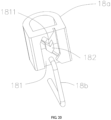
- the restriction block 18a is fixed and slidably connected to the connection post 161 in the mobile cavity 1152.
- One side of the wall of the restriction block 18a is provided with a channel 181.
- an arrow-shaped raised rib 182 is arranged in the middle of the channel 181, to make a M-shaped passage form inside the channel 181.
- the channel 181 is provided with a recessed point 1811 which is recessed downwards.
- the side walls of the channel 181 are equipped with inclined planes that are guided in conjunction with the raised ribs 182.
- channel 181 may not be limited to the M-shaped passage configuration in this embodiment, and the channel 181 may also be configured in other shapes with a recessed point 1811.
- restriction rod 18b One end of the restriction rod 18b is fixed in the mounting hole 1155, and the other end of the restriction rod 18b corresponds to a raised rib 182 and can be movably connected in the channel 181, so that the end of the restriction rod 18b can move with the movement of the restriction block 18a, and move to the recessed point 1811 of the channel 181 to engage or separate, thereby achieving the positioning and resetting of the moving block 16.
- the process of the moving block 16 moving within the moving cavity 1152 through the restriction block 18a and the restriction rod 18b is roughly as follows: as shown in FIG 20 and FIG. 21 , if the moving block 16 is pressed, the connection post 161 will drive the restriction block 18a to move within the moving cavity 1152. At this time, the end of the restriction rod 18b moves to clamp with the recessed point 1811 of the channel 181 under the guidance of the raised rib 182 and the side wall of the channel 181, so that the moving block 16 can be positioned and fixed in the receiving cavity 115, at this point, the first spring 103 is in a compressed state.
- the restriction block 18a moves with the connection post 161 in the moving cavity 1152, so that the end of the restriction rod 18b can move to separate from the recessed point 1811 of the channel 181 under the guidance of the raised rib 182 and the side wall of the channel 181. Therefore, when the external force on the moving block 16 is withdrawn, the end of the restriction rod 18b can move again in the channel 181, finally, under the force of the first spring 103, the moving block 16 is driven to move and reset (as shown in FIG 21 ).
Landscapes
- Engineering & Computer Science (AREA)
- Multimedia (AREA)
- Toys (AREA)
Description
- The present disclosure relates to the technical field of toys, particularly to a sliding puzzle toy.
- At present, sliding puzzle toys include two types: flat puzzle toys and sliding puzzle toys. In related arts, sliding puzzle toys generally include a main body and a plurality of sliders. The plurality of sliders slide on the surface of the main body to create corresponding patterns. Because the slider gap on the surface of the main body is only one grid, in order to achieve the goal of creating a complete pattern, the slider must be cleverly moved. Therefore, this type of toy is both interesting and can exercise intelligence of user, especially for inspiring children's intelligence. However, due to the presence of a slider gap, not only dust and other impurities can easily enter the main body, but also affect the overall aesthetics of the sliding puzzle toy. In related art, separable puzzle unit blocks are provided on the main body to open or close the slider gap, such as a puzzle toy disclosed in patent document
CN203469438U . - The US patent (
US2009230621A1 ) discloses a ball-shaped puzzle, which relates to a ball-shaped puzzle including a spherical support element and a plurality of movable puzzle elements which all have substantially the same size and shape, the movable puzzle elements being slidably engaged in a trajectory on the outside of the spherical support element, the trajectory defining a plurality of predetermined positions on the outside of the spherical support element between which the puzzle elements are movable. The spherical support element comprises a core and a plurality of trajectory forming elements (15; 45-46) which form the trajectory (2; 32), the trajectory forming elements being fixed onto the core by a snap-fitting arrangement. - The US patent (
US7243918B2 ) discloses an extension for rotatable puzzle piece. The extension for a rotatable puzzle piece that is used with a sliding puzzle, and a sliding puzzle that uses the same. In one aspect the puzzle has an extension for a rotatable puzzle piece, comprising a housing including a backing frame and a front member connected one to the other. The backing frame is formed with a fixedly disposed first recess defined by walls formed on the backing frame. A fixedly disposed second recess is defined by the front member. The puzzle also includes a plurality of puzzle pieces disposed in the second recess, wherein each of the pieces is individually slidably movable in the second recess, whereby the pieces are movable so as to be arranged in a desired solution in the second recess. A channel operatively communicates with the second recess such that the pieces can be moved into the channel and rotated therein, thereby rotationally reorienting the pieces. The rotationally reoriented pieces can be moved into the second recess in an attempt to solve the puzzle.However, in the structure of the puzzle toy disclosed in the above patent documents, the separable puzzle unit blocks are connected to the cylinder (i.e. the main body) through an open structure, which is complex and not conducive to simplifying assembly materials, reducing manufacturing costs, and also not conducive to improving the assembly efficiency of the puzzle toy. - The present disclosure aims to solve at least one of the technical problems existing in the existing technology. Therefore, this present disclosure provides a sliding puzzle toy, aiming to solve the problem of complex connection structure between separable puzzle unit blocks and the main body in existing puzzle toys, which is not conducive to reducing costs and improving work efficiency.
- To achieve the above objective, a sliding puzzle toy is provided by the present disclosure, including a main body and a plurality of sliders slidably connected to the main body, wherein the main body comprises two bottom walls and a side wall connected between the two bottom walls, at least one of the two bottom walls is provided with a recessed slot and a separable block, one side of the recessed slot is connected to the side wall, an arc transition is provided at a connection between the recessed slot and the side wall, and the separable block is movably or detachtably connected to the recessed slot; an outer surface of the side wall is provided with a plurality of sliding grooves that intersects with each other along circumferential and longitudinal directions, the sliding grooves are movably connected to the sliders, and one of the longitudinal sliding grooves passes through a connection between the recessed slot and the side wall and extends towards a bottom wall of the recessed slot;
- the separable block is slidably connected within the recessed slot, and a length of the separable block is equal to or less than a length of the recessed slot;
- the length of the separable block is less than the length of the recessed slot, some part of the recessed slot is recessed to form a receiving cavity, a moving block is movably connected within the receiving cavity, and the moving block has a first state adjacent to the separable block and a second state overlapping with the separable block;
- the side wall of the recessed slot is provided with a guide slot along a direction of movement of the separable block, the separable block is provided with a first sliding plate on the side wall opposite to the guide slot, and the first sliding plate and the guide slot are in a concave-convex sliding fit;
- the side wall of the recessed slot is provided with a limit slot along a direction of movement of the separable block, the separable block is provided with a second sliding plate on the side wall opposite to the limit slot, and the second sliding plate and the limit slot are in a concave-convex sliding fit; and
- the recessed slots include at least two sub slots that intersect with each other, an intersection position of any two sub slots is recessed to form the receiving cavity, and each sub slot is provided with at least one separable block in a sliding manner.As the preferred solution, the separable block matches with the recessed slot, one side of the separable block is detachably connected to an open side of the recessed slot, and an other side of the separable block is pivoted to a side wall of the recessed slot.
- As the preferred solution, two side walls opposite each other in the recessed slot are respectively provided with a connection slot, two side walls opposite each other of the separable block are respectively provided with snap bulges, and the snap bulges are arranged corresponding to the connection slot and is detachably connected in the connection slot.
- As the preferred solution, a bottom wall of the recessed slot is provided with a positioning slot adjacent to the connection slot, the two side walls opposite each other of the separable block protrude towards a position of the positioning slot to form snap blocks, and the snap blocks match with the positioning slot and detachably connected to the positioning slot.
- As the preferred solution, the separable block is connected to the bottom wall through a connection strip, the connection strip is accommodated and connected between the separable block and the bottom wall, and the two ends of the connection strip are respectively pivoted to the separable block and the bottom wall.
- As the preferred solution, any separable block is provided with the guide slot on the side wall adjacent to the moving block.
- As the preferred solution, a bottom wall of the receiving cavity is further provided with a moving cavity, and the moving block is provided with a connection post on the side wall corresponding to the moving cavity, and the connection post is movably connected within the moving cavity.
- As the preferred solution, the bottom wall of the receiving cavity is connected to the moving block and/or a bottom wall of the moving cavity is connected to the connection post through at least one elastic member.
- As the preferred solution, a side wall of the moving cavity are circumferentially provided with a plurality of guiding ribs at intervals, and each end of the guiding ribs is provided with a first inclined surface, the first inclined surface is arranged in an inclined Z-shaped shape, and the connection post is movably connected to the moving cavity through a pushing block and a limit block;
the pushing block is fixed to the connection post and is slidably connected between the plurality of guiding ribs, and an end of the pushing block in the moving cavity is provided with serrated claws in a circumferential direction; and the limit block is connected to a bottom wall of the moving cavity through an elastic member, and an outer wall of the limit block is provided with a plurality of positioning ribs; each positioning rib is slidably connected between any two guiding ribs, each positioning rib is provided with a second inclined surface at an end opposite to the serrated claws, the second inclined surface contacts with the serrated claws, and an inclination direction and an inclination angle of each second inclined surface are the same as those of the first inclined surface. - As the preferred solution, the bottom wall of the moving cavity is provided with a mounting hole, and the connection post is movably connected to the moving cavity through a restriction block and a restriction rod;
- the restriction block is fixed to the connection post and is slidably connected in the moving cavity, one side of the restriction block is provided with a channel, the channel is provided with a recessed point recessed downwards; and
- one end of the restriction rod is fixed in the mounting hole, and an other end of the restriction rod is movably connected in the channel and connected or separated from the recessed point.
- As the preferred solution,the side wall is a closed curved surface, or the side wall includes at least three closed connected planes, and each two adjacent planes are connected by an arc-shaped transition surface.
- As the preferred solution, each slider includes a plate and a base pillar arranged along a vertical direction, the plate is exposed to the side wall, the base pillar is movably connected in the sliding groove, a positioning piece is slidably sleeve on the base pillar, the positioning piece is movably connected to the sliding groove and contacts with an inner wall of the sliding groove, and an elastic member is connected between the positioning piece and an end of the base pillar.
- Therefore, based on the technical means of the present disclosure, a brief explanation of the advantages that the present disclosure can achieve is as follows: In the sliding puzzle toy provided by the present disclosure, by setting the recessed slot on the bottom wall, the recessed slot and the side wall are connected to serve as a slider gap; and at the same time, by setting the separable block on the bottom wall that is movably or detachtably connected with the recessed slot, such that the separable block can be flipped or moved within the recessed slot, or can be separated and disassembled from the recessed slot. When in use, through flipping, moving or disassembling the separable block to open or close the slider gap. Compared with existing structures, by setting the recessed slots and separable blocks which movably or detachtably connected with each other on the bottom wall, it can effectively simplify the connection structure between the separable block and the main body, which is beneficial for reducing costs and improving assembly efficiency. Moreover, by setting the recessed slots and separable blocks which movably or detachtably connected with each other on the bottom wall, it can make the opening or closing of the separable block simpler and faster, making it easier for game operations. It can also separate the separable block from the slider, compared with the existing structure, the pattern formed by the splicing of several sliders on the side wall is not limited by the separable block (pattern), and the relative position of the splicing pattern on the side wall can be changed at any time, making the sliding puzzle toy more playable and lasting appeal.
-
-
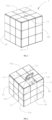
FIG 1 is a schematic diagram of a sliding puzzle toy in the first embodiment of this present disclosure. -
FIG 2 is a schematic diagram of the separable block in opened state of the sliding puzzle toy inFIG 1 . -
FIG 3 is a schematic diagram of the main body inFIG 2 . -
FIG 4 is a schematic diagram when the sliding puzzle toy inFIG 2 is used. -
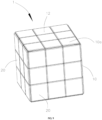
FIG 5 is a schematic diagram of the slider inFIG 1 . -
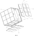
FIG 6 is an exploded view of the slider inFIG 5 . -
FIG 7 is a schematic diagram of the slider inFIG 2 connected to the main body. -
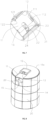
FIG 8 is a schematic diagram when a sliding puzzle toy in the second embodiment of this present disclosure is used. -
FIG 9 is a schematic diagram of a sliding puzzle toy in the third embodiment of this present disclosure. -
FIG 10 is a schematic diagram of the separable block in opened state of the sliding puzzle toy inFIG 9 . -
FIG 11 is a partial exploded view of the sliding puzzle toy inFIG 9 . -
FIG 12 is a cross-sectional schematic diagram of the sliding puzzle toy inFIG 9 . -
FIG 13 is a schematic diagram of the separable block in opened state of the sliding puzzle toy in the fourth embodiment of the present disclosure. -
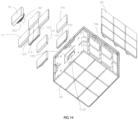
FIG 14 is a partial exploded view of the sliding puzzle toy inFIG 13 . -
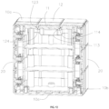
FIG 15 is a cross-sectional schematic diagram of the sliding puzzle toy inFIG 13 . -
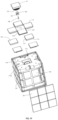
FIG 16 is a partial exploded view of a sliding puzzle toy in the fifth embodiment of the present disclosure. -
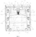
FIG 17 is a cross-sectional schematic diagram of the sliding puzzle toy inFIG 16 . -
FIG 18 is a partially cross-sectional schematic diagram of the moving block inFIG 16 , which is movably connected in the receiving cavity by a pushing block and a limit block. -
FIG 19 is a partial exploded view of a sliding puzzle toy according to the sixth embodiment of the present disclosure. -
FIG 20 is a schematic diagram of the connection between the restriction block and the restriction rod inFIG 19 . -
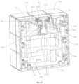
FIG 21 is a cross-sectional schematic diagram of the sliding puzzle toy inFIG 19 . - In the picture: 1- sliding puzzle toy; 10- main body; 10a - bottom wall; 11- recessed slot; 111-connection slot; 112- positioning slot; 110- sub slot; 113- guide slot; 114- limit slot; 115- receiving cavity; 1151- retaining ring; 1152- moving cavity; 1153- guiding rib; 1154- first inclined surface; 1155- mounting hole; 12- separable block; 121- snap bulge; 122- snap block; 123- first sliding plate; 124- second sliding plate;13- connection strip; 10b - side wall; 14- circumferential sliding groove; 15- longitudinal sliding groove; 101- plane; 102- arc-shaped transition surface; 16- moving block; 161- connection post; 17a - pushing block; 171- serrated claw; 17b - limit block; 172- positioning rib; 173- second inclined surface; 18a - restriction block; 181-channel; 1811- recessed point; 182-raised rib; 18b - restriction rod; 103- first spring; 104- second spring; 20- slider; 21- plate; 22- base pillar; 23- positioning piece; 24- elastic member.
- The following will provide a clear and complete description of the technical solution in the embodiments of this present disclosure in conjunction with the attached drawings. Obviously, the described embodiments are only a part of the embodiments of this present disclosure, not all of them. Based on the embodiments in this present disclosure, all other embodiments obtained by ordinary skilled person in the art without creative labor fall within the scope of this present disclosure. It can be understood that the attached drawings are only for reference and illustration purposes and are not intended to limit the present disclosure. The connections shown in the attached drawings are only for the purpose of clear description and do not limit the connection method.
- It should be understood that the terms "up", "down", "front", "back", "left", "right", "top", "bottom", "inside", "outside", etc. are based on the attached drawings to describe the direction or position relationship shown in the present disclosure. They are only for the convenience of describing the present disclosure and simplifying the description, rather than indicating that the device or component referred to must have a special direction or position relationship, thus, it cannot be understood as a limitation on the present present disclosure. Further, it should be noted that when a component is considered to be "connected" to another component, it may be directly or indirectly connected to another component. Unless otherwise defined, all technical and scientific terms used in this article have the same meanings as those commonly understood by the skilled person in the art of this present disclosure. The terms used in the specification of this present disclosure are only for the purpose of describing specific embodiments and are not intended to limit this present disclosure.
- Please refer to
FIG. 1 to FIG 7 , the first embodiment provides a slidingpuzzle toy 1, which includes amain body 10 and a plurality ofsliders 20 that can be slidably connected to themain body 10. In this embodiment, themain body 10 is roughly arranged in a square shape, including twobottom walls 10a and aside wall 10b connected between the twobottom walls 10a. It can be understood that since themain body 10 is roughly arranged in a square shape, the twobottom walls 10a are correspondingly arranged as squares, and theside walls 10b include four closedconnected planes 101, wherein each twoadjacent planes 101 are connected with an arc-shapedtransition surface 102 to enable thesliders 20 to move more smoothly on theside walls 10b. It should be noted that the side length ofbottom wall 10a is equal to the sum of the side length ofside wall 10b and the thickness of twosliders 20. so as to make the outer surface of the slidingpuzzle toy 1 smooth and tidy when theslider 20 is connected to themain body 10, making it easy to play. - In other embodiments of present disclosure, the
main body 10 can also be arranged in other cylindrical structures, such as a cylinder (a sliding puzzle toy provided by the second embodiment as shown inFIG. 8 ), a triangular prism, or other multi prism structures. When themain body 10 is arranged in a cylinder, thebottom wall 10a is circular, and theside wall 10b is a closed curved surface; When themain body 10 is arranged in a triangular prism or other multi prism structure, thebottom wall 10a is a triangle or other polygon, and theside wall 10b includes three or a corresponding number ofplanes 101. Similarly, there is an arc-shapedtransition surface 102 connected between every twoadjacent planes 101. When themain body 10 is arranged in other columnar structures, the length or diameter of thebottom wall 10a and theside wall 10b should be adjusted adaptively based on the principle of making the outer surface of the slidingpuzzle toy 1 smooth and tidy. - In the first embodiment, one of the
bottom walls 10a is provided with a recessedslot 11 and aseparable block 12. One side of the recessedslot 11 is connected to theside wall 10b to enable the recessedslot 11 to serve as a slider gap, and the connection between the recessedslot 11 and theside wall 10b has an arc-shaped transition to enablesliders 20 to move more smoothly between the recessedslot 11 and theside wall 10b. In other embodiments of present disclosure, it is not limited to setting recessedslots 11 andseparable blocks 12 on only onebottom wall 10a, but can also set recessedslots 11 andseparable blocks 12 on bothbottom walls 10a simultaneously. The number of recessedslots 11 andseparable blocks 12 on eachbottom wall 10a can also be two, three, or more. - In the first embodiment, two
connection slots 111 and two positioningslots 112 are also recessed inside the recessedslot 11. The twoconnection slots 111 are located on opposite sides of the walls inside the recessedslot 11, which are detachably connected to the part of theseparable block 12. The twopositioning slots 112 are located on the bottom wall of recessedslot 11 and are adjacent to oneconnection slot 111, respectively, which are detachably connected to another part of theseparable block 12. In other embodiments of present disclosure, the recessedslot 11 may not be equipped with aconnection slot 111 and/or apositioning slot 112. - In the first embodiment, the
separable block 12 is matched with the recessedslot 11, and one side of theseparable block 12 is detachably connected to the open side of the recessedslot 11. The other side of theseparable block 12 is pivoted to the side wall of the recessedslot 11 through theconnection strip 13. Wherein theconnection strip 13 is accommodated and connected between theseparable block 12 and thebottom wall 10a, and the two ends of theconnection strip 13 are respectively pivoted with theseparable block 12 and thebottom wall 10a. The setting of theconnection strip 13 allows theseparable block 12 to have a high degree of rotational freedom relative to thebottom wall 10a. It can be understood that theseparable block 12 and the recessedslot 11, which are pivoted and matched on thebottom wall 10a, can open or close the slider gap during the relative rotation of theseparable block 12, allowing theslider 20 to move on themain body 10 to ensure the game can proceed, and can close the slider gap when idle to prevent dust and maintain the overall aesthetics of the slidingpuzzle toy 1. In other embodiments of present disclosure, theseparable block 12 can also be directly pivoted with the side wall of the recessedslot 11. Obviously, in other embodiments, theseparable block 12 matches with the recessedslot 11 can also be directly and detachably connected to the recessedslot 11. When in use, the slider gap can be opened or closed by placing theseparable block 12 in the recessedslot 11 or disassembling and separating theseparable block 12 from the recessedslot 11. - In the first embodiment, the two side walls opposite each other of the
separable block 12 are respectively provided with onesnap bulge 121 and onesnap block 122, wherein the snap bulge is arranged corresponding to theconnection slot 111 and is detachably connected to theconnection slot 111, which is used to enable theseparable block 12 to be stably connected to the recessedslot 11 when the slidingpuzzle toy 1 is idle, preventing theseparable block 12 from detaching from the recessedslot 11 under gravity. Thesnap block 122 is located on the side facing thepositioning slot 112 on the side wall of theseparable block 12. Thesnap block 122 is matched with thepositioning slot 112 and is detachably connected to thepositioning slot 112, playing a role in positioning and fixing theseparable block 12 and the recessedslot 11 in collaboration with thesnap bulge 121 and theconnection slot 111. In other embodiments of present disclosure, when there is noconnection slot 111 and/orpositioning slot 112 in the recessedslot 11, theseparable block 12 is also not provided with asnap bulge 121 and/or asnap block 122. - It should be noted that the structural design of setting the recessed
slot 11 andseparable block 12 on thebottom wall 10a has the advantage of a more streamlined and compact connection structure between theseparable block 12 and thebottom wall 10a compared to the structure of setting the separable puzzle unit blocks on the side wall in existing technology, which is beneficial for reducing production costs and improving assembly efficiency. Moreover, setting the recessedslot 11 and theseparable block 12 on thebottom wall 10a not only facilitates the operation of flipping theseparable block 12, but also enables theslider 20 to move on theside wall 10b without being limited by the pattern of theseparable block 12. - The outer surface of the
side wall 10b is provided with a plurality of the sliding grooves which are intersected with each other along the circumferential and longitudinal directions, and the sliding groove is movably connected with a part structure ofslider 20. In the first embodiment, the sliding groove includes threecircumferential sliding grooves 14 and twelve longitudinal slidinggrooves 15, wherein one longitudinal slidinggroove 15 passes through the connection between the recessedslot 11 and theside wall 10b and extends towards the bottom wall of the recessedslot 11 to enable theslider 20 to enter and exit the recessedslot 11 under the guidance of the longitudinal slidinggroove 15. In other embodiments of present disclosure, the number ofcircumferential sliding grooves 14 and longitudinal slidinggrooves 15 can be adaptively adjusted according to the number and arrangement ofsliders 20. - Each
slider 20 includes aplate 21 and abase pillar 22 arranged in a vertical direction, wherein theplate 21 is exposed on theside wall 10b and matched with theside wall 10b, that is, when theside wall 10b is a closed curved surface, theplate 21 is an arc-shaped plate; when theside wall 10b is connected by multiple closed planes, theplate 21 is a flat plate. A pattern can be set on theplate 21 through spraying, adhesive connection, snap-fit connection, buckle connection, threaded connection, bolt connection, or magnetic connection. The patterns ofseveral plates 21 can be spliced to form a complete large pattern, and the game can be played by restoring the disrupted patterns ofseveral plates 21. - The
base pillar 22 passes through the sliding groove to movably connect theslider 20 within the sliding groove. In the first embodiment, apositioning piece 23 is slidably sleeved on thebase pillar 22, and thepositioning piece 23 is movably connected in the sliding groove along with thebase pillar 22 and contacts with the inner wall of the sliding groove. There is an elastic member 24 (such as a spring, etc.) connected between thepositioning piece 23 and the end of thebase pillar 22, which is used for providing an extra space forslider 20 to move smoothly on themain body 10 when theslider 20 crosses the connection between the recessedslot 11 and theside wall 10b and when theslider 20 crosses any arc-shapedtransition surface 102, ensuring that the slidingpuzzle toy 1 has a good gaming feel. In the other embodiments, theslider 20 can also adopt other structures to achieve the purpose of being movable and connected within the sliding groove, for example, a magnet may be provided fixed at the end of thebase pillar 22 in eachslider 20, and the magnet is movably connected in the sliding groove along with thebase pillar 22. At this time, a magnetic film is set on the outer side on theside wall 10b opposite to the magnet, and the magnetic film is magnetically connected to the magnet to slidably connect theslider 20 to themain body 10. - During the game, the
separable block 12 is rotated to open the recessedslot 11. By manually pushing theplate 21, thebase pillar 22 is driven to move between the circumferential slidinggrooves 14 and the longitudinal slidinggrooves 15 which are intersected with each other, in order to change the relative position of anyslider 20 on theside wall 10b, until the disrupted large pattern is restored to end the game. - Please refer to
FIG 9 to FIG 12 , a slidingpuzzle toy 1 of the third embodiment of the present disclosure is provided, which differs from the first embodiment in that theseparable block 12 can be slidably connected within the recessedslot 11. In the third embodiment, the length of theseparable block 12 is equal to the length of the recessedslot 11. At this time, the other side of the recessedslot 11 is connected to the outside, making the recessed slot 11 a straight structure with both ends intercommunicated. By pushing theseparable block 12 forward or backward, the recessedslot 11 can be opened or closed. Moreover, the other side of the recessedslot 11 can also be intercommunicated to theside wall 10b at the same time. By pushing theseparable block 12 forward or backward, the recessedslot 11 can be can opened to increase the utilization convenience of the sliding puzzle toy. In other embodiments of the present disclosure, the other side of the recessedslot 11 can also be set only to be connected to the outside. - In order to ensure that the
separable block 12 is securely slidably connected within the recessedslot 11, aguide slot 113 is provided on the side wall of the recessedslot 11 along the movement direction of theseparable block 12. Theseparable block 12 is provided with a first slidingplate 123 on the side wall opposite to theguide slot 113, and the first slidingplate 123 and theguide slot 113 are in a concave-convex sliding fit. In the third embodiment, in order to make it difficult for theseparable block 12 to detach from the recessedslot 11, the bottom wall of the recessedslot 11 is further provided with alimit slot 114 along the movement direction of theseparable block 12. Theseparable block 12 is provided with a second slidingplate 124 on the side wall opposite to thelimit slot 114, and the second slidingplate 124 and thelimit slot 114 are in a concave-convex sliding fit. Obviously, in other embodiments, the bottom wall of the recessedslot 11 may not be equipped with alimited slot 114, and at this time, theseparable block 12 may not be correspondingly equipped with a second slidingplate 124. - Please refer to
FIG. 13 to FIG 15 , a slidingpuzzle toy 1 of the fourth embodiment of the present disclosure is provided, which differs from the third embodiment is that in the fourth embodiment, the length of theseparable block 12 is smaller than the length of the recessedslot 11. At this time, the part of the recessedslot 11 far away from theside wall 10b is recessed to form a receivingcavity 115, and the receivingcavity 115 is connected to a movingblock 16 through an elastic member (such as the first spring 103). As the movingblock 16 moves within the receivingcavity 115, the movingblock 16 has a first state adjacent to the separatingblock 12 and a second state overlapped with the separatingblock 12. Therefore, when the movingblock 16 moves downwards towards the receivingcavity 115, it can still move the separatingblock 12 within the recessedslot 11 to the second state overlapped with the movingblock 16, achieving the opening of the recessedslot 11. - In other embodiments of the present disclosure, the receiving
cavity 115 in the recessedslot 11 can also be set adjacent to theside wall 10b according to different shapes and structures of the puzzle toy. The movingblock 16 can also be movably connected to the receivingcavity 115 through other means, such as a structure with concave-convex moving fit, a structure with meshing moving fit, etc. - In the fourth embodiment, the recessed
slot 11 includes twosub slots 110 that intersect with each other in a cross shape. The intersection position of the twosub slots 110 is recessed to form a receivingcavity 115, and eachsub slot 110 is sliding with twoseparable blocks 12. By pushing anyseparable block 12 to move and overlap with the movingblock 16, the recessedslot 11 can be opened, so as to increase the utilization convenience of the sliding puzzle toy. It can be understood that since recessedslot 11 is composed of two cross intersectingsub slots 110, fourseparable blocks 12 are respectively moved and set at the midpoint positions of the four sides of thebottom wall 10a on onebottom wall 10a of themain body 10. At this time, guideslots 113 are set on either of the two vertical edges of the recessedslot 11 inbottom wall 10a, and first slidingplates 123 are set on both sides opposite to theguide slots 113 in anyseparable block 12. Meanwhile, anyseparable block 12 is further provided withguide slots 113 on the side wall adjacent to the movingblock 16, allowing anyseparable block 12 to move onto the movingblock 16. In other embodiments of the present invention, according to the shape and setting requirements of themain body 10, the recessedslot 11 may also include three or moreintersecting sub slots 110. At this time, the intersection position of any twosub slots 110 is recessed to form a receivingcavity 115, and at least oneseparable block 12 is sliding inside eachsub slot 110. - In the fourth embodiment, the bottom wall of the receiving
cavity 115 is provided with aretaining ring 1151. The end of thefirst spring 103 is detachably clamped and fixed on theretaining ring 1151, the other end of thefirst spring 103 is in contact with the movingblock 16, allowing the movingblock 16 to move towards the receivingcavity 115 under external force. At the same time, when the external force on the movingblock 16 is withdrawn, the movingblock 16 can be pushed to reset through thefirst spring 103, so that the movingblock 16 can transform between the first state and the second state. It can be understood that in order to guide the movingblock 16 to move in the correct direction within the receivingcavity 115, the bottom wall of the receiving cavity 3313 is also provided with a movingcavity 1152. At this time, the movingblock 16 is provided with aconnection post 161 on the side wall corresponding to the movingcavity 1152, and theconnection post 161 can be movably connected within the movingcavity 1152. In other embodiments of the present invention, the receivingcavity 115 may not be provided with a movingcavity 1152, accordingly, the movingblock 16 is not provided with aconnection post 161. The bottom wall of the movingcavity 1152 and theconnection post 161 can also be connected through an elastic member (such as a spring) to enhance the ability of the movingblock 16 to reset automatically. - Please refer to
FIG 16 to FIG 18 , a slidingpuzzle toy 1 of the fifth embodiment of the present invention is provided, which differs from the fourth embodiment is that there are a plurality of guidingribs 1153 arranged at circumferential intervals on the side walls of the movingcavity 1152, and the end of each guidingrib 1153 is provided with a firstinclined surface 1154. The firstinclined surface 1154 is arranged in an inclined Z-shaped shape. At this time, there is nofirst spring 103 set on theretaining ring 1151, theconnection post 161 can be movably connected in the movingcavity 1152 through the pushingblock 17a and thelimit block 17b, so that when the external force on the movingblock 16 is withdrawn, it is still possible to fix the movingblock 16 in the receivingcavity 115 through the connection between the guidingribs 1153, the pushingblock 17a and thelimit block 17b. - The pushing
block 17a is fixedly and slidably connected with theconnection post 161 between the plurality of guidingribs 1153, so that the pushingblock 17a needs to move back and forth in the direction limited by the guidingribs 1153. The pushingblock 17a is provided withserrated claws 171 in the circumferential direction at the end of the movingcavity 1152, which are used to contact with thelimit block 17b to push thelimit block 17b to move within the movingcavity 1152. - The
limit block 17b is connected to the bottom wall of the movingcavity 1152 through an elastic member (such as the second spring 104), and the outer wall of thelimit block 17b is provided with a plurality ofpositioning ribs 172. Eachpositioning rib 172 is slidably connected between any two guidingribs 1153, so that thelimit block 17b needs to move back and forth in the direction restricted by the guidingribs 1153. Eachpositioning rib 172 is provided with a secondinclined surface 173 at the end opposite to theserrated claws 171. The secondinclined surface 173 contacts to theserrated claws 171, so that thelimit block 17b can slide on the guidingribs 1153 under the driving force of the pushingblock 17a. The inclination direction and the inclination angle of each secondinclined surface 173 are the same as those of the firstinclined surface 1154, so that the secondinclined surface 173 can move along the firstinclined surface 1154 when moving to the endpoint position of the firstinclined surface 1154, therefore, eachpositioning rib 172 can rotate and move between adjacent guidingribs 1153 to achieve the positioning and resetting of the movingblock 16. - It should be noted that the process of moving
block 16 moving within the movingcavity 1152 by the pushingblock 17a and thelimit block 17b is roughly as shown inFIG 17 andFIG 18 . If the movingblock 16 is pressed, the pushingblock 17a will push thelimit block 17b to slide within the guidingribs 1153 through theserrated claws 171. At this time, thesecond spring 104 is in a compressed state. When thelimit block 17b moves to the intersection of point A of the secondinclined surface 173 and the firstinclined surface 1154, thelimit block 17b will be pushed by the elastic force of thesecond spring 104, causing the secondinclined surface 173 to cross point A and move along the firstinclined surface 1154 to point B of the firstinclined surface 1154. At this time, thepositioning rib 172 will be clamped on the firstinclined surface 1154, enabling the movingblock 16 to be positioned and fixed in the receivingcavity 115, further increasing the utilization convenience of the sliding puzzle toy. If the movingblock 16 is pressed again, the pushingblock 17a will push thelimit block 17b again to slide within the firstinclined surface 1154. At this time, thesecond spring 104 is in a compressed state. When thelimit block 17b moves to the intersection of point C on the secondinclined surface 173 and the firstinclined surface 1154, when the external force on the movingblock 16 is withdrawn, thelimit block 17b will be pushed by the elastic force of thesecond spring 104, enabling the secondinclined surface 173 cross point C and move along the firstinclined surface 1154 between any two guidingribs 1153. Finally, under the force of thesecond spring 104, the pushingblock 17a is pushed to drive the movingblock 16 to move and reset (as shown inFIG 17 ). - Please refer to
FIG 19 to FIG 21 , a slidingpuzzle toy 1 of the sixth embodiment of the present invention is provided, which differs from the fourth embodiment is that the bottom wall of the movingcavity 1152 is provided with a mountinghole 1155. At this time, the receivingcavity 115 and the movingblock 16 are still connected by thefirst spring 103. Theconnection post 161 can be movably connected in the movingcavity 1152 through therestriction block 18a and therestriction rod 18b to achieve that when external force on the movingblock 16 is withdrawn, it is still possible to fix the movingblock 16 in the receivingcavity 115 through the connection between therestriction block 18a and therestriction rod 18b. - The
restriction block 18a is fixed and slidably connected to theconnection post 161 in themobile cavity 1152. One side of the wall of therestriction block 18a is provided with achannel 181. In the sixth embodiment, an arrow-shaped raisedrib 182 is arranged in the middle of thechannel 181, to make a M-shaped passage form inside thechannel 181. At this time, thechannel 181 is provided with a recessedpoint 1811 which is recessed downwards. It should be noted that in order to limit the movement path of therestriction rod 18b within thechannel 181, the side walls of thechannel 181 are equipped with inclined planes that are guided in conjunction with the raisedribs 182. In other embodiments of the present invention,channel 181 may not be limited to the M-shaped passage configuration in this embodiment, and thechannel 181 may also be configured in other shapes with a recessedpoint 1811. - One end of the
restriction rod 18b is fixed in the mountinghole 1155, and the other end of therestriction rod 18b corresponds to a raisedrib 182 and can be movably connected in thechannel 181, so that the end of therestriction rod 18b can move with the movement of therestriction block 18a, and move to the recessedpoint 1811 of thechannel 181 to engage or separate, thereby achieving the positioning and resetting of the movingblock 16. - It should be noted that the process of the moving
block 16 moving within the movingcavity 1152 through therestriction block 18a and therestriction rod 18b is roughly as follows: as shown inFIG 20 andFIG. 21 , if the movingblock 16 is pressed, theconnection post 161 will drive therestriction block 18a to move within the movingcavity 1152. At this time, the end of therestriction rod 18b moves to clamp with the recessedpoint 1811 of thechannel 181 under the guidance of the raisedrib 182 and the side wall of thechannel 181, so that the movingblock 16 can be positioned and fixed in the receivingcavity 115, at this point, thefirst spring 103 is in a compressed state. If the movingblock 16 is pressed again, therestriction block 18a moves with theconnection post 161 in the movingcavity 1152, so that the end of therestriction rod 18b can move to separate from the recessedpoint 1811 of thechannel 181 under the guidance of the raisedrib 182 and the side wall of thechannel 181. Therefore, when the external force on the movingblock 16 is withdrawn, the end of therestriction rod 18b can move again in thechannel 181, finally, under the force of thefirst spring 103, the movingblock 16 is driven to move and reset (as shown inFIG 21 ). - For clarity, certain features described in the embodiments of this present disclosure can be combined for use in one embodiment. Moreover, the various features of the present present disclosure described in a single embodiment can also be used individually or in any suitable form in sub combinations.
Claims (9)
- A sliding puzzle toy, comprising a main body (10) and a plurality of sliders (20) slidably connected to the main body (10), wherein the main body (10) comprises one bottom wall and one top wall (10a) and a side wall (10b) connected between the one bottom wall and the one top wall (10a), at least one of the one bottom wall and the one top wall (10a) is provided with a recessed slot (11) and a separable block (12), one side of the recessed slot (11) is connected to the side wall (10b), an arc transition is provided at a connection between the recessed slot (11) and the side wall (10b), and the separable block (12) is movably or detachtably connected to the recessed slot (11); an outer surface of the side wall (10b) is provided with a plurality of sliding grooves that intersects with each other along circumferential and longitudinal directions, the sliding grooves are movably connected to the sliders (20), and one of the longitudinal sliding grooves passes through a connection between the recessed slot (11) and the side wall (10b) and extends towards a bottom wall of the recessed slot (11), characterized in that,the separable block (12) is slidably connected within the recessed slot (11), and a length of the separable block (12) is equal to or less than a length of the recessed slot (11);the length of the separable block (12) is less than the length of the recessed slot (11), some part of the recessed slot (11) is recessed to form a receiving cavity (115), a moving block (16) is movably connected within the receiving cavity (115), and the moving block (16) includes a first state adjacent to the separable block (12) and a second state overlapping with the separable block (12);a side wall of the recessed slot (11) is provided with a guide slot (113) along a direction of movement of the separable block (12), the separable block (12) is provided with a first sliding plate (123) on the side wall opposite to the guide slot (113), and the first sliding plate (123) and the guide slot (113) are in a concave-convex sliding fit; andthe recessed slots (11) include at least two sub slots (110) that intersect with each other, an intersection position of any two sub slots (110) is recessed to form thereceiving cavity (115), and each sub slot (110) is provided with at least one separable block (12) in a sliding manner.
- The sliding puzzle toy according to claim 1, characterized in that the separable block (12) matches with the recessed slot (11), one side of the separable block (12) is detachably connected to an open side of the recessed slot (11), and an other side of the separable block (12) is pivoted to a side wall of the recessed slot (11).
- The sliding puzzle toy according to claim 2, characterized in that the separable block (12) is connected to the bottom wall (10a) through a connection strip (13), the connection strip (13) is accommodated and connected between the separable block (12) and the bottom wall, and the two ends of the connection strip (13) are respectively pivoted to the separable block (12) and the bottom wall (10a).
- The sliding puzzle toy according to claim 1, characterized in that any separable block (12) is provided with the guide slot (113) on the side wall adjacent to the moving block (16) .
- The sliding puzzle toy according to claim 1, characterized in that a bottom wall of the receiving cavity (115) is further provided with a moving cavity (1152), and the moving block (16) is provided with a connection post (161) on the side wall corresponding to the moving cavity (1152), and the connection post (161) is movably connected within the moving cavity (1152).
- The sliding puzzle toy according to claim 5, characterized in that the bottom wall of the receiving cavity (115) is connected to the moving block (16) and/or a bottom wall of the moving cavity (1152) is connected to the connection post (161) through at least one elastic member (24).
- The sliding puzzle toy according to claim 5, characterized in that a side wall of the moving cavity (1152) are circumferentially provided with a plurality of guiding ribs (1153) at intervals, and each end of the guiding ribs (1153) is provided with a first inclined surface (1154), the first inclined surface (1154) is arranged in an inclined Z-shaped shape, and the connection post (161) is movably connected to the moving cavity (1152) through a pushing block (17a) and a limit block (17b);the pushing block (17a) is fixed to the connection post (161) and is slidably connected between the plurality of guiding ribs (1153), and an end of the pushing block (17a) in the moving cavity (1152) is provided with serrated claws (171) in a circumferential direction; andthe limit block (17b) is connected to a bottom wall of the moving cavity (1152) through an elastic member (24), and an outer wall of the limit block (17b) is provided with a plurality of positioning ribs (172); each positioning rib (172) is slidably connected between any two guiding ribs (1153), each positioning rib (172) is provided with a second inclined surface (173) at an end opposite to the serrated claws (171), the second inclined surface (173) contacts with the serrated claws (171), and an inclination direction and an inclination angle of each second inclined surface (173) are the same as those of the first inclined surface (1154).
- The sliding puzzle toy according to claim 6, characterized in that the bottom wall of the moving cavity (1152) is provided with a mounting hole (1155), and the connection post (161) is movably connected to the moving cavity (1152) through a restriction block (18a) and a restriction rod (18b);the restriction block (18a) is fixed to the connection post (161) and is slidably connected in the moving cavity (1152), one side of the restriction block (18a) is provided with a channel (181), the channel (181) is provided with a recessed point (1811) recessed downwards; andone end of the restriction rod (18b) is fixed in the mounting hole (1155), and an other end of the restriction rod (18b) is movably connected in the channel (181) and connected or separated from the recessed point (1811).
- The sliding puzzle toy according to claim 1-8, characterized in that each slider (20) comprises a plate (21) and a base pillar (22) arranged along a vertical direction, the plate (21) is exposed to the side wall (10b), the base pillar (22) is movably connected in the sliding groove, a positioning piece (23) is slidably sleeved on the base pillar (22), the positioning piece (23) is movably connected to the sliding groove and contacts with an inner wall of the sliding groove, and an elastic member (24) is connected between the positioning piece (23) and an end of the base pillar (22).
Applications Claiming Priority (2)
| Application Number | Priority Date | Filing Date | Title |
|---|---|---|---|
| CN202320056772.1U CN219185786U (en) | 2023-01-09 | 2023-01-09 | Sliding jigsaw puzzle |
| CN202322716462.0U CN221155333U (en) | 2023-10-10 | 2023-10-10 | Opening and closing structure of jigsaw puzzle and three-dimensional jigsaw puzzle |
Publications (3)
| Publication Number | Publication Date |
|---|---|
| EP4397383A1 EP4397383A1 (en) | 2024-07-10 |
| EP4397383C0 EP4397383C0 (en) | 2025-07-09 |
| EP4397383B1 true EP4397383B1 (en) | 2025-07-09 |
Family
ID=89121700
Family Applications (1)
| Application Number | Title | Priority Date | Filing Date |
|---|---|---|---|
| EP23214654.8A Active EP4397383B1 (en) | 2023-01-09 | 2023-12-06 | Sliding puzzle toy |
Country Status (3)
| Country | Link |
|---|---|
| US (1) | US12383817B2 (en) |
| EP (1) | EP4397383B1 (en) |
| JP (1) | JP3245553U (en) |
Family Cites Families (18)
| Publication number | Priority date | Publication date | Assignee | Title |
|---|---|---|---|---|
| DE3039513A1 (en) * | 1980-10-20 | 1982-05-19 | Mandl, Klaus, Dipl.-Ing., 8900 Augsburg | Permutation game with sliding counters - alters row sequence by movements in different directions for different distances |
| US4526372A (en) * | 1982-01-20 | 1985-07-02 | Kikis Evangelos T | Puzzle toy |
| FR2549381B1 (en) * | 1983-07-22 | 1987-02-20 | Gueytron Jean Claude | IMPROVEMENTS TO GAMES CALLED "PUZZLE" |
| GB2176410A (en) * | 1985-06-17 | 1986-12-31 | Chow Hwa Ong | Cube puzzle |
| US4872682A (en) * | 1987-11-17 | 1989-10-10 | Ravi Kuchimanchi | Cube puzzle with moving faces |
| WO1994027694A1 (en) * | 1993-05-26 | 1994-12-08 | Lopez Victor Hugo | Three dimensional puzzle |
| DE9418860U1 (en) * | 1994-11-24 | 1995-02-23 | Feller, Erhard, 59555 Lippstadt | Sliding game with (dis) locking flap |
| FR2790972A1 (en) * | 1999-03-17 | 2000-09-22 | Bruno Mutel | Play cube with different face sliding plates |
| FR2797195A1 (en) * | 1999-08-02 | 2001-02-09 | Jean Marc Huguet | Logic ball puzzle comprises surface composed of pentagon and curved hexagon elements and empty space for curved element, curved elements moved by runners over sphere surface |
| US7243918B2 (en) * | 2003-06-05 | 2007-07-17 | Robert D Vernon | Extension for rotatable puzzle piece |
| DE602006001588D1 (en) * | 2005-02-25 | 2008-08-07 | Dpt | BALLOON PUZZLE PLAY |
| US7547019B2 (en) * | 2007-03-19 | 2009-06-16 | Ying-Jen Chen | Three-dimensional DIY assembly intelligence structure |
| DE202008002004U1 (en) * | 2008-02-13 | 2008-04-17 | Scherpe, Andreas, Dr. | Logical stereo toy |
| US8387984B2 (en) * | 2010-04-07 | 2013-03-05 | Bahry Uri Management Ltd. | Manipulative three-dimensional puzzle |
| CN203469438U (en) | 2013-07-18 | 2014-03-12 | 广州灵动创想文化科技有限公司 | Jigsaw puzzle |
| TWI630017B (en) * | 2017-04-28 | 2018-07-21 | 楊儒勳 | Multi-axis rotating puzzle educational toys |
| KR102062307B1 (en) * | 2017-06-13 | 2020-01-03 | 울산과학기술원 | maze-type cube block |
| CN112996577B (en) * | 2018-08-18 | 2024-04-12 | 曹阳 | Spatial maze with reconfigurable paths |
-
2023
- 2023-12-05 US US18/529,959 patent/US12383817B2/en active Active
- 2023-12-06 EP EP23214654.8A patent/EP4397383B1/en active Active
- 2023-12-07 JP JP2023004399U patent/JP3245553U/en active Active
Also Published As
| Publication number | Publication date |
|---|---|
| JP3245553U (en) | 2024-02-05 |
| EP4397383C0 (en) | 2025-07-09 |
| US12383817B2 (en) | 2025-08-12 |
| US20240226711A1 (en) | 2024-07-11 |
| EP4397383A1 (en) | 2024-07-10 |
Similar Documents
| Publication | Publication Date | Title |
|---|---|---|
| CN108568089B (en) | Magnetic positioning magic cube | |
| US11484780B1 (en) | Magnetic levitation magic cube | |
| US20160317911A1 (en) | Device with multi-directional moving members | |
| CN112996577A (en) | Spatial maze with reconfigurable paths | |
| JP7393037B2 (en) | 3D puzzle | |
| EP4397383A1 (en) | Sliding puzzle toy | |
| KR102937106B1 (en) | Magnetic Block Toys | |
| US4418915A (en) | Puzzle of stacked segments | |
| US20200276495A1 (en) | Sliding intelligence toy | |
| CN218572800U (en) | Jigsaw puzzle | |
| US8360432B2 (en) | Three-dimensional and spherical sliding puzzle | |
| KR20240022966A (en) | Transformable toy | |
| CN219185786U (en) | Sliding jigsaw puzzle | |
| CN205995051U (en) | Magnetic splicing building block | |
| EP3456396B1 (en) | Folding toy | |
| RU226313U1 (en) | Sliding puzzle toy | |
| CN215538363U (en) | Magnetic positioning and magnetic deceleration magic cube edge block structure | |
| JPH11300026A (en) | Rotary type spherical body-fitting toy | |
| US12434132B2 (en) | Detachable sliding toy | |
| CN113952704A (en) | Adjustable magnetic structure of magic cube | |
| US12383816B2 (en) | Sliding puzzle | |
| CN101002987A (en) | rotatable sphere puzzle | |
| TWI832446B (en) | A maze box | |
| CN221964460U (en) | Chess board with ejection structure | |
| CN223516930U (en) | Key toy |
Legal Events
| Date | Code | Title | Description |
|---|---|---|---|
| PUAI | Public reference made under article 153(3) epc to a published international application that has entered the european phase |
Free format text: ORIGINAL CODE: 0009012 |
|
| STAA | Information on the status of an ep patent application or granted ep patent |
Free format text: STATUS: REQUEST FOR EXAMINATION WAS MADE |
|
| 17P | Request for examination filed |
Effective date: 20231230 |
|
| AK | Designated contracting states |
Kind code of ref document: A1 Designated state(s): AL AT BE BG CH CY CZ DE DK EE ES FI FR GB GR HR HU IE IS IT LI LT LU LV MC ME MK MT NL NO PL PT RO RS SE SI SK SM TR |
|
| GRAP | Despatch of communication of intention to grant a patent |
Free format text: ORIGINAL CODE: EPIDOSNIGR1 |
|
| STAA | Information on the status of an ep patent application or granted ep patent |
Free format text: STATUS: GRANT OF PATENT IS INTENDED |
|
| INTG | Intention to grant announced |
Effective date: 20250324 |
|
| GRAS | Grant fee paid |
Free format text: ORIGINAL CODE: EPIDOSNIGR3 |
|
| GRAA | (expected) grant |
Free format text: ORIGINAL CODE: 0009210 |
|
| STAA | Information on the status of an ep patent application or granted ep patent |
Free format text: STATUS: THE PATENT HAS BEEN GRANTED |
|
| AK | Designated contracting states |
Kind code of ref document: B1 Designated state(s): AL AT BE BG CH CY CZ DE DK EE ES FI FR GB GR HR HU IE IS IT LI LT LU LV MC ME MK MT NL NO PL PT RO RS SE SI SK SM TR |
|
| REG | Reference to a national code |
Ref country code: GB Ref legal event code: FG4D |
|
| REG | Reference to a national code |
Ref country code: CH Ref legal event code: EP |
|
| REG | Reference to a national code |
Ref country code: IE Ref legal event code: FG4D |
|
| U01 | Request for unitary effect filed |
Effective date: 20250710 |
|
| U07 | Unitary effect registered |
Designated state(s): AT BE BG DE DK EE FI FR IT LT LU LV MT NL PT RO SE SI Effective date: 20250717 |
|
| PG25 | Lapsed in a contracting state [announced via postgrant information from national office to epo] |
Ref country code: IS Free format text: LAPSE BECAUSE OF FAILURE TO SUBMIT A TRANSLATION OF THE DESCRIPTION OR TO PAY THE FEE WITHIN THE PRESCRIBED TIME-LIMIT Effective date: 20251109 |
|
| PG25 | Lapsed in a contracting state [announced via postgrant information from national office to epo] |
Ref country code: NO Free format text: LAPSE BECAUSE OF FAILURE TO SUBMIT A TRANSLATION OF THE DESCRIPTION OR TO PAY THE FEE WITHIN THE PRESCRIBED TIME-LIMIT Effective date: 20251009 |
|
| PG25 | Lapsed in a contracting state [announced via postgrant information from national office to epo] |
Ref country code: HR Free format text: LAPSE BECAUSE OF FAILURE TO SUBMIT A TRANSLATION OF THE DESCRIPTION OR TO PAY THE FEE WITHIN THE PRESCRIBED TIME-LIMIT Effective date: 20250709 |
|
| PG25 | Lapsed in a contracting state [announced via postgrant information from national office to epo] |
Ref country code: GR Free format text: LAPSE BECAUSE OF FAILURE TO SUBMIT A TRANSLATION OF THE DESCRIPTION OR TO PAY THE FEE WITHIN THE PRESCRIBED TIME-LIMIT Effective date: 20251010 |
|
| PG25 | Lapsed in a contracting state [announced via postgrant information from national office to epo] |
Ref country code: PL Free format text: LAPSE BECAUSE OF FAILURE TO SUBMIT A TRANSLATION OF THE DESCRIPTION OR TO PAY THE FEE WITHIN THE PRESCRIBED TIME-LIMIT Effective date: 20250709 |
|
| PG25 | Lapsed in a contracting state [announced via postgrant information from national office to epo] |
Ref country code: RS Free format text: LAPSE BECAUSE OF FAILURE TO SUBMIT A TRANSLATION OF THE DESCRIPTION OR TO PAY THE FEE WITHIN THE PRESCRIBED TIME-LIMIT Effective date: 20251009 |
|
| PG25 | Lapsed in a contracting state [announced via postgrant information from national office to epo] |
Ref country code: ES Free format text: LAPSE BECAUSE OF FAILURE TO SUBMIT A TRANSLATION OF THE DESCRIPTION OR TO PAY THE FEE WITHIN THE PRESCRIBED TIME-LIMIT Effective date: 20250709 |
|
| U20 | Renewal fee for the european patent with unitary effect paid |
Year of fee payment: 3 Effective date: 20260101 |
|
| PG25 | Lapsed in a contracting state [announced via postgrant information from national office to epo] |
Ref country code: SM Free format text: LAPSE BECAUSE OF FAILURE TO SUBMIT A TRANSLATION OF THE DESCRIPTION OR TO PAY THE FEE WITHIN THE PRESCRIBED TIME-LIMIT Effective date: 20250709 |
|
| PG25 | Lapsed in a contracting state [announced via postgrant information from national office to epo] |
Ref country code: CZ Free format text: LAPSE BECAUSE OF FAILURE TO SUBMIT A TRANSLATION OF THE DESCRIPTION OR TO PAY THE FEE WITHIN THE PRESCRIBED TIME-LIMIT Effective date: 20250709 |
|
| PG25 | Lapsed in a contracting state [announced via postgrant information from national office to epo] |
Ref country code: SK Free format text: LAPSE BECAUSE OF FAILURE TO SUBMIT A TRANSLATION OF THE DESCRIPTION OR TO PAY THE FEE WITHIN THE PRESCRIBED TIME-LIMIT Effective date: 20250709 |
|
| PLBE | No opposition filed within time limit |
Free format text: ORIGINAL CODE: 0009261 |
|
| STAA | Information on the status of an ep patent application or granted ep patent |
Free format text: STATUS: NO OPPOSITION FILED WITHIN TIME LIMIT |