EP4397362A1 - Schwimmender ultraviolettgenerator - Google Patents
Schwimmender ultraviolettgenerator Download PDFInfo
- Publication number
- EP4397362A1 EP4397362A1 EP22864862.2A EP22864862A EP4397362A1 EP 4397362 A1 EP4397362 A1 EP 4397362A1 EP 22864862 A EP22864862 A EP 22864862A EP 4397362 A1 EP4397362 A1 EP 4397362A1
- Authority
- EP
- European Patent Office
- Prior art keywords
- water
- irradiator
- light source
- lower case
- floating
- Prior art date
- Legal status (The legal status is an assumption and is not a legal conclusion. Google has not performed a legal analysis and makes no representation as to the accuracy of the status listed.)
- Pending
Links
Images


Classifications
-
- A—HUMAN NECESSITIES
- A61—MEDICAL OR VETERINARY SCIENCE; HYGIENE
- A61N—ELECTROTHERAPY; MAGNETOTHERAPY; RADIATION THERAPY; ULTRASOUND THERAPY
- A61N5/00—Radiation therapy
- A61N5/06—Radiation therapy using light
- A61N5/0613—Apparatus adapted for a specific treatment
-
- A—HUMAN NECESSITIES
- A61—MEDICAL OR VETERINARY SCIENCE; HYGIENE
- A61N—ELECTROTHERAPY; MAGNETOTHERAPY; RADIATION THERAPY; ULTRASOUND THERAPY
- A61N5/00—Radiation therapy
- A61N5/06—Radiation therapy using light
- A61N5/0613—Apparatus adapted for a specific treatment
- A61N5/0616—Skin treatment other than tanning
-
- A—HUMAN NECESSITIES
- A61—MEDICAL OR VETERINARY SCIENCE; HYGIENE
- A61H—PHYSICAL THERAPY APPARATUS, e.g. DEVICES FOR LOCATING OR STIMULATING REFLEX POINTS IN THE BODY; ARTIFICIAL RESPIRATION; MASSAGE; BATHING DEVICES FOR SPECIAL THERAPEUTIC OR HYGIENIC PURPOSES OR SPECIFIC PARTS OF THE BODY
- A61H33/00—Bathing devices for special therapeutic or hygienic purposes
- A61H33/005—Electrical circuits therefor
- A61H2033/0083—Illumination
-
- A—HUMAN NECESSITIES
- A61—MEDICAL OR VETERINARY SCIENCE; HYGIENE
- A61H—PHYSICAL THERAPY APPARATUS, e.g. DEVICES FOR LOCATING OR STIMULATING REFLEX POINTS IN THE BODY; ARTIFICIAL RESPIRATION; MASSAGE; BATHING DEVICES FOR SPECIAL THERAPEUTIC OR HYGIENIC PURPOSES OR SPECIFIC PARTS OF THE BODY
- A61H2201/00—Characteristics of apparatus not provided for in the preceding codes
- A61H2201/10—Characteristics of apparatus not provided for in the preceding codes with further special therapeutic means, e.g. electrotherapy, magneto therapy or radiation therapy, chromo therapy, infrared or ultraviolet therapy
-
- A—HUMAN NECESSITIES
- A61—MEDICAL OR VETERINARY SCIENCE; HYGIENE
- A61H—PHYSICAL THERAPY APPARATUS, e.g. DEVICES FOR LOCATING OR STIMULATING REFLEX POINTS IN THE BODY; ARTIFICIAL RESPIRATION; MASSAGE; BATHING DEVICES FOR SPECIAL THERAPEUTIC OR HYGIENIC PURPOSES OR SPECIFIC PARTS OF THE BODY
- A61H33/00—Bathing devices for special therapeutic or hygienic purposes
-
- A—HUMAN NECESSITIES
- A61—MEDICAL OR VETERINARY SCIENCE; HYGIENE
- A61N—ELECTROTHERAPY; MAGNETOTHERAPY; RADIATION THERAPY; ULTRASOUND THERAPY
- A61N5/00—Radiation therapy
- A61N5/06—Radiation therapy using light
- A61N2005/0626—Monitoring, verifying, controlling systems and methods
-
- A—HUMAN NECESSITIES
- A61—MEDICAL OR VETERINARY SCIENCE; HYGIENE
- A61N—ELECTROTHERAPY; MAGNETOTHERAPY; RADIATION THERAPY; ULTRASOUND THERAPY
- A61N5/00—Radiation therapy
- A61N5/06—Radiation therapy using light
- A61N2005/063—Radiation therapy using light comprising light transmitting means, e.g. optical fibres
-
- A—HUMAN NECESSITIES
- A61—MEDICAL OR VETERINARY SCIENCE; HYGIENE
- A61N—ELECTROTHERAPY; MAGNETOTHERAPY; RADIATION THERAPY; ULTRASOUND THERAPY
- A61N5/00—Radiation therapy
- A61N5/06—Radiation therapy using light
- A61N2005/0632—Constructional aspects of the apparatus
-
- A—HUMAN NECESSITIES
- A61—MEDICAL OR VETERINARY SCIENCE; HYGIENE
- A61N—ELECTROTHERAPY; MAGNETOTHERAPY; RADIATION THERAPY; ULTRASOUND THERAPY
- A61N5/00—Radiation therapy
- A61N5/06—Radiation therapy using light
- A61N2005/0635—Radiation therapy using light characterised by the body area to be irradiated
- A61N2005/0642—Irradiating part of the body at a certain distance
-
- A—HUMAN NECESSITIES
- A61—MEDICAL OR VETERINARY SCIENCE; HYGIENE
- A61N—ELECTROTHERAPY; MAGNETOTHERAPY; RADIATION THERAPY; ULTRASOUND THERAPY
- A61N5/00—Radiation therapy
- A61N5/06—Radiation therapy using light
- A61N2005/0658—Radiation therapy using light characterised by the wavelength of light used
- A61N2005/0661—Radiation therapy using light characterised by the wavelength of light used ultraviolet
-
- A—HUMAN NECESSITIES
- A61—MEDICAL OR VETERINARY SCIENCE; HYGIENE
- A61N—ELECTROTHERAPY; MAGNETOTHERAPY; RADIATION THERAPY; ULTRASOUND THERAPY
- A61N5/00—Radiation therapy
- A61N5/06—Radiation therapy using light
- A61N2005/0664—Details
- A61N2005/0668—Apparatus adapted for operation in a moist environment, e.g. bath or shower
Definitions
- the present disclosure relates to an ultraviolet irradiator and, more particularly, to a floating ultraviolet irradiator that floats on water in a bathtub and emits ultraviolet rays (UV-B) in a specific wavelength range (280-320 nm), which are effective in synthesizing vitamin D in the body or treating skin diseases, toward a person taking a lower-body bath or a whole-body bath.
- UV-B ultraviolet rays
- ultraviolet rays refers to electromagnetic radiation having a wavelength longer than X-rays and shorter than visible rays.
- ultraviolet rays are close to the purple band and have a wavelength range of 100 to 3800 angstroms, which is not visible to the human eye.
- Ultraviolet rays have a lower power of penetration than ordinary X-rays or gamma rays but have higher energy than visible rays, so that ultraviolet rays are known to affect human skin or small organisms. Accordingly, ultraviolet rays are generally used for sterilization and disinfection and are also called actinic rays because of strong chemical actions.
- UV-A accounts for more than 90% of ultraviolet rays and is considered the main cause of skin aging.
- UV-B has a shorter wavelength than UV-A, and does not penetrate deep into the skin, but converts provitamin D into vitamin D, which acts to produce immune cells, and is known to be effective in treating skin diseases.
- UV-B is directly exposed to the eyes, eye damage such as cataracts may occur, so careful attention is required.
- UV-C is used in various forms across a variety of industrial fields such as green algae remover, household disinfection devices, home or industrial air purifiers, and water treatment devices due to its excellent sterilization effect.
- UV-B is not widely utilized due to problems of conventional technologies.
- An example of a conventional technology that uses UV-B to synthesize vitamin D in the body or treat skin diseases is a stand-up type of a skincare device.
- a product that emits ultraviolet rays by attaching an ultraviolet lamp to the upper end of the stand it is necessary to wear dedicated goggles (goggles for UV protection) for safety and it is cumbersome to change clothes for use since the body should be exposed.
- the conventionally known stand-type of a skincare device has problems in that dedicated goggles should be worn for use, there is the inconvenience of having to change separate clothes to expose the skin, and there is also the inconvenience of storage and usage due to the stand for fixing the ultraviolet lamp at a certain height.
- a technical task that the present disclosure seeks to solve is to provide a floating ultraviolet irradiator that helps synthesize vitamin D in the body or treat skin diseases by emitting toward the body in the water the ultraviolet rays (UV-B) in a specific wavelength range (280-320 nm) while floating on the water filled in the bathtub when a person takes a lower-body bath or whole-body bath.
- UV-B ultraviolet rays
- Another technical task that the present disclosure seeks to solve is to provide a floating ultraviolet irradiator that reduces the inconvenience caused by changing clothes, does not require dedicated goggles thanks to added safety functions (a function that automatically detects when heaving or flipping over occurs and immediately stops the generation of ultraviolet rays (UV-B)), and increases the convenience of use by making it easy to store.
- added safety functions a function that automatically detects when heaving or flipping over occurs and immediately stops the generation of ultraviolet rays (UV-B)
- a floating ultraviolet irradiator that includes
- the present disclosure may include a main controller mounted on an upper surface of the substrate opposite to the surface where the UV light source is mounted and the main controller is provided with a gravity sensor (G Sensor).
- G Sensor gravity sensor
- the main controller may be driven to immediately stop the generation of UV rays by cutting off the power supply to the UV light source when some of at least more than two water detectors do not detect contact with water in the switch ON state.
- the present disclosure further may include a plurality of body detection sensors electrically connected to the main controller and mounted on the peripheral surface of the upper cover, and in this case, the main controller may immediately stop the generation of UV rays by cutting off the power supply to the UV light source when the body is not detected within a preset detection range of the body detection sensors in the switch ON state.
- the present disclosure may include a user detection pad installed in the water and composed of a load cell and a wireless transmitter for transmitting information, wherein a wireless receiver mounted on the substrate is configured to receive a signal transmitted by the user detection pad.
- the main controller may be driven to immediately stop the generation of UV rays by cutting off the power supply to the UV light source when a user load is not detected on the user detection pad in the switch ON state.
- a light-blocking visor that blocks UV rays reflected in the water from returning to the surface of the water may be formed continuously in the peripheral direction on the radially outermost surface of the upper cover or lower case.
- the water detector may be a capacitance sensor or a resistance measuring sensor that measures the electrical resistance of water, and at least more than two detectors may be disposed at equal intervals around the periphery of the substrate.
- the buoyancy generating means applied to the floating ultraviolet irradiator according to the present disclosure may be air being filled in the mounting space disconnected from the outside or a float made of a material having a specific gravity less than 1, such as Styrofoam.
- the floating ultraviolet irradiator may include a safety distance maintaining member to be coupled to the lower case in order to maintain a minimum safety distance from the user's body located in the water when used while floating on water.
- the floating ultraviolet irradiator may float on the water by its own buoyancy and is configured to irradiate ultraviolet rays (UV-B) in a specific wavelength range (280 ⁇ 320 nm) toward the water while floating in a normal posture on the water. Accordingly, the user may have the effects of synthesizing vitamin D in the body or treating skin diseases by using the present disclosure when taking the lower body bath or the whole body bath.
- UV-B ultraviolet rays
- the present disclosure may automatically detect safety-threatening events when the user lifts arbitrarily the device or the device is heaving or overturned due to waves, and then immediately stop the generation of UV rays, thereby preventing safety accidents according to direct exposure of ultraviolet rays (UV-B) to the user's eyes and consequently improving the reliability of safety.
- UV-B ultraviolet rays
- the present disclosure may be used while floating on the water when taking a lower-body bath or a whole-body bath, and has the advantages of reducing the inconvenience caused by changing clothes, not requiring dedicated goggles thanks to added safety functions (a function that automatically detects when heaving or flipping over occurs and immediately stops the generation of ultraviolet rays (UV-B)), and increasing the convenience of use by making it easy to store.
- added safety functions a function that automatically detects when heaving or flipping over occurs and immediately stops the generation of ultraviolet rays (UV-B)
- FIG. 1 is an exploded perspective view of a floating ultraviolet irradiator according to an exemplary embodiment of the present disclosure.
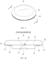
- FIG. 2 is a combined perspective view of a floating ultraviolet irradiator shown in FIG. 1 .
- FIG. 3a is a cross-sectional view of a floating ultraviolet irradiator when viewed in a direction from the line A-A shown in FIG. 2
- FIG. 4 is a bottom perspective view of a substrate shown in FIG. 1 .
- FIG. 5 is a conceptual diagram that extracts and shows only the main components of the present disclosure.
- the lower case 20 may be in the form of a polygonal (or circular) container having a protruding part 22 protruding downward to the extent of a specific height while the upper part where the upper cover 50 is coupled is open.
- the lower case 20 may be composed of an insulator such as plastic, and an opening 24 of a predetermined area may be formed in the center of a protruding part 22 protruding downward.
- the UV transmission window 30 may be coupled to the opening 24 to be in a sealed state.
- the UV transmission window 30 may be composed of transparent or translucent synthetic resin or glass that may transmit ultraviolet rays (UV-B) generated by a UV light source 42 described later. Additionally, the UV light source 42 that transmits UV rays through the UV transmission window 30 may be mounted on one surface of the substrate 40. Preferably, the UV light source 42 may be mounted in the center of the lower surface of the substrate 40 at a position corresponding to that of the UV transmission window 30 on the basis of the height direction of the product as shown in FIGS. 3a and 5 .
- UV-B ultraviolet rays
- the UV light source 42 may be an ultraviolet light emitting diode (UV LED) that generates UV-B with a light wavelength range of 280 to 320 nm and the main controller 44 may be mounted on the other surface (the upper surface of the substrate 40) opposite to the surface on which the UV light source 42 is mounted. At this time, the main controller 44 may control the power supply between the built-in battery (not shown) and the UV light source 42 on the basis of the output of the water detector 46 and the gravity sensor 48 to be described later.
- UV LED ultraviolet light emitting diode
- the combination of the upper cover 50 and the lower case 20 may be implemented (when the planar shape of the upper cover 50 and lower case 20 is polygonal) to be tightly coupled to each other using a protrusion-groove (or groove-protrusion) coupling method by configuring each of a protrusion and a groove (55 and 25, or grooves and protrusions) that may be mutually interlocked with each other in the peripheral direction at the inner surface of the open end of the upper cover 50 and the outer surface of the open end of the lower case 20 as shown in the drawing (a cross-sectional view in FIGS. 3a and 3b ).
- a protrusion-groove or groove-protrusion
- the upper cover 50 and the lower case 20 may be tightly coupled to each other through screw coupling between the female screw threads and the male screw threads by configuring a female screw thread to be formed on the inner surface of the open end of the upper cover 50 and a male screw thread to be formed on the outer surface of the open end of the lower case 20.
- This coupling method may be a coupling method applicable when the planar shape of the upper cover 50 and the lower case 20 is a circular planar shape.
- a sealed mounting space disconnected from the outside may be formed inside as described above due to the tight coupling of the upper cover 50 and the lower case 20 as mentioned above.
- the ultraviolet irradiator may float on the water by the buoyancy generating means in the sealed mounting space and a water detector 46 may be mounted on the periphery of the substrate 40 in contact with the edge portion of the lower case 20.
- the buoyancy generating means applied to the floating ultraviolet irradiator according to the present disclosure may be air being filled in the mounting space disconnected from the outside or a float made of a material having a specific gravity less than 1, such as Styrofoam.
- the water detector 46 may serve to detect contact with water when the ultraviolet irradiator according to the exemplary embodiment of the present disclosure floats on the water with its own buoyancy (the buoyancy due to air filled in the sealed mounting space).
- the water detector 46 may preferably be a capacitance sensor that detects contact with water from a capacitance that changes upon contact with water and may be mounted in a plurality of two or more around the periphery of the substrate 40.
- the water detector 46 may be not limited to the capacitance sensor. In some cases, a resistance measuring sensor that measures electrical resistance by being in direct contact with water may be applied as the water detector. In this case, as shown in FIG. 3b , each of the water detectors 46 may be configured to pass through a sensor penetration hole (not shown) formed at a corresponding position of the lower case 20 such that a portion of the lower end protrudes downward from the lower case 20.
- At least more than two water detectors 46 may be disposed at equal intervals in the peripheral direction on the edge (a portion that contacts the edge of the lower case 20 when assembling the product) of the lower surface of the substrate 40.
- the detectors may be mounted on the edge of the lower surface of the substrate 40 at 45 degree intervals and the information (whether or not it is in contact with water) sensed by the water detector 46 may be provided to the main controller 44.
- the main controller 44 may control the power supply to the UV light source 42 on the basis of information provided by the water detector 46. More specifically, the ultraviolet irradiator 10 according to an exemplary embodiment of the present disclosure may immediately stop the generation of UV rays by cutting off the power supply to the UV light source 42 when some of a plurality of water detectors 46 do not detect contact with water in the switch ON state.
- the main controller 44 may normally allow the power supply to the UV light source 42 when the ultraviolet irradiator 10 according to the present disclosure is so stably floating on the water that all water detectors 46 are in contact with water and may immediately cut off the power supply and prevent UV rays from being directly exposed to a user's eyes when the device is lifted or is heaving or overturned due to contact with a user or waves while floating on water.
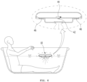
- FIG. 6 is a view showing a use state of a floating ultraviolet irradiator according to an exemplary embodiment of the present disclosure, and is an exemplary view of a use state of the present disclosure when taking a lower-body bath or a whole-body bath in a state in which the ultraviolet irradiator according to an exemplary embodiment of the present disclosure is floating on water filled in a bathtub.
- the main controller 44 may determine that the device 10 is normally floating on the water only under the conditions that all water detectors 46 detect contact with water and the output of the gravity sensor 48 is in the normal range and then allow the generation of UV rays, and may determine that other conditions are conditions that affect the user's safety and then immediately stop the generation of UV rays.
- FIG. 7 is an exemplary diagram of the use state showing the use state of a floating ultraviolet irradiator according to another preferred exemplary embodiment of the present disclosure, and shows a configuration in which a body detection sensor is further added in addition to the configuration of the exemplary embodiment described above.
- the floating ultraviolet irradiator 10 may further include a body detection sensor 49.
- the body detection sensor 49 may be mounted at regular intervals in the peripheral direction of the upper cover 50 to be electrically connected to the main controller 44 on the upper surface of the substrate 40 and serve to detect whether the body is exposed above the surface of the water within a preset sensing range in a state when the device 10 is floating in a normal position on the surface of water, that is, floating on the water, and transmit the corresponding information to the main controller 44.
- a wireless receiver 66 may be mounted on the substrate 40 to wirelessly receive a signal transmitted by the user detection pad 60, and a processor programmed to stop the generation of UV rays by cutting off the power supply to the UV light source 42 may be mounted on the main controller 44 when the information that a user load is not detected is received from the user detection pad 60 in a state when the device 10 is floating in a normal posture on the water after the switch is on.
Landscapes
- Health & Medical Sciences (AREA)
- Engineering & Computer Science (AREA)
- Biomedical Technology (AREA)
- Life Sciences & Earth Sciences (AREA)
- General Health & Medical Sciences (AREA)
- Public Health (AREA)
- Pathology (AREA)
- Animal Behavior & Ethology (AREA)
- Veterinary Medicine (AREA)
- Nuclear Medicine, Radiotherapy & Molecular Imaging (AREA)
- Radiology & Medical Imaging (AREA)
- Biophysics (AREA)
- Physical Water Treatments (AREA)
- Chemical & Material Sciences (AREA)
- Electrochemistry (AREA)
- Physical Education & Sports Medicine (AREA)
- Rehabilitation Therapy (AREA)
- Pain & Pain Management (AREA)
- Chemical Kinetics & Catalysis (AREA)
- Epidemiology (AREA)
- Physics & Mathematics (AREA)
- Analytical Chemistry (AREA)
- Biochemistry (AREA)
- General Physics & Mathematics (AREA)
- Immunology (AREA)
- Radiation-Therapy Devices (AREA)
Applications Claiming Priority (2)
| Application Number | Priority Date | Filing Date | Title |
|---|---|---|---|
| KR1020210115746A KR102703834B1 (ko) | 2021-08-31 | 2021-08-31 | 부유식 자외선 발생기 |
| PCT/KR2022/010375 WO2023033353A1 (ko) | 2021-08-31 | 2022-07-15 | 부유식 자외선 발생기 |
Publications (2)
| Publication Number | Publication Date |
|---|---|
| EP4397362A1 true EP4397362A1 (de) | 2024-07-10 |
| EP4397362A4 EP4397362A4 (de) | 2025-07-09 |
Family
ID=85411303
Family Applications (1)
| Application Number | Title | Priority Date | Filing Date |
|---|---|---|---|
| EP22864862.2A Pending EP4397362A4 (de) | 2021-08-31 | 2022-07-15 | Schwimmender ultraviolettgenerator |
Country Status (6)
| Country | Link |
|---|---|
| US (1) | US20240278035A1 (de) |
| EP (1) | EP4397362A4 (de) |
| JP (1) | JP2024533192A (de) |
| KR (1) | KR102703834B1 (de) |
| CN (1) | CN117915986A (de) |
| WO (1) | WO2023033353A1 (de) |
Family Cites Families (14)
| Publication number | Priority date | Publication date | Assignee | Title |
|---|---|---|---|---|
| JPS5754443U (de) * | 1980-09-17 | 1982-03-30 | ||
| DE20311963U1 (de) * | 2003-07-31 | 2003-12-11 | Dse Stehle Elektronik Gmbh | Fernsteuereinheit |
| US8109981B2 (en) * | 2005-01-25 | 2012-02-07 | Valam Corporation | Optical therapies and devices |
| KR20110045232A (ko) * | 2009-10-26 | 2011-05-04 | 주식회사 리직스 | 저출력 레이저 치료 부유구 |
| KR20170036173A (ko) * | 2015-09-23 | 2017-04-03 | 서울바이오시스 주식회사 | Uv led 물 살균 장치 |
| KR20180107074A (ko) | 2015-11-30 | 2018-10-01 | 커민 에스피. 제트 오.오. | 피부 질환을 치료하기 위한 컴팩트 uvb 광치료장치 |
| KR101716643B1 (ko) | 2016-07-14 | 2017-03-15 | 주식회사 해인엘이디 | Led램프를 이용한 양어장 살균장치 |
| AU2017316641B2 (en) * | 2016-08-23 | 2021-09-16 | REMUV Technologies Inc. | Portable disinfection device |
| KR20200002082A (ko) * | 2018-06-29 | 2020-01-08 | 주부경 | Uv led를 이용한 밀폐용기 자외선살균기 |
| KR102183301B1 (ko) * | 2018-07-23 | 2020-11-26 | 서경한 | 휴대 가능한 화장실 악취제거 장치 |
| US10941978B2 (en) * | 2018-12-10 | 2021-03-09 | Midea Group Co., Ltd. | Refrigerator fluid dispenser with dispensed volume calculation |
| CN210992647U (zh) * | 2019-08-09 | 2020-07-14 | 上海希格玛高技术有限公司 | 一种光疗装置的led阵列辐照器 |
| KR102857445B1 (ko) * | 2019-09-06 | 2025-09-09 | 서울바이오시스 주식회사 | 광 조사 장치 |
| KR102148227B1 (ko) * | 2019-12-13 | 2020-08-27 | 노블웍스 주식회사 | 가습기 내부에 넣는 플로팅 타입 uv led 소독장치 |
-
2021
- 2021-08-31 KR KR1020210115746A patent/KR102703834B1/ko active Active
-
2022
- 2022-07-15 WO PCT/KR2022/010375 patent/WO2023033353A1/ko not_active Ceased
- 2022-07-15 JP JP2024514090A patent/JP2024533192A/ja active Pending
- 2022-07-15 US US18/687,074 patent/US20240278035A1/en active Pending
- 2022-07-15 EP EP22864862.2A patent/EP4397362A4/de active Pending
- 2022-07-15 CN CN202280058925.4A patent/CN117915986A/zh active Pending
Also Published As
| Publication number | Publication date |
|---|---|
| CN117915986A (zh) | 2024-04-19 |
| JP2024533192A (ja) | 2024-09-12 |
| US20240278035A1 (en) | 2024-08-22 |
| WO2023033353A1 (ko) | 2023-03-09 |
| KR102703834B1 (ko) | 2024-09-05 |
| EP4397362A4 (de) | 2025-07-09 |
| KR20230032674A (ko) | 2023-03-07 |
Similar Documents
| Publication | Publication Date | Title |
|---|---|---|
| KR101596653B1 (ko) | 자외선 광 방출용 장치 | |
| ES2279813T3 (es) | Sistema de deteccion perimetrica y contenedor automatico. | |
| CN100580507C (zh) | 眼镜、眼镜架、辐射监测的方法及用于辐射监测的电子电路 | |
| US9868651B2 (en) | Solar disinfection of fluid | |
| KR20160059141A (ko) | 표지 기능과 살균 기능을 동시에 제공하는 화장품 케이스 | |
| EP4397362A1 (de) | Schwimmender ultraviolettgenerator | |
| CN210493617U (zh) | 一种杀菌保温水杯 | |
| ES2860528T3 (es) | Conjunto de monitor para bebés | |
| CN209404314U (zh) | 紫外杀菌杯盖及具有该杯盖的水杯 | |
| CN211561183U (zh) | 用于马桶的深紫外线消毒系统 | |
| JP6897218B2 (ja) | リモコン装置 | |
| US20200345876A1 (en) | Sterilizer | |
| CN212490827U (zh) | 一种led紫外杀菌灯 | |
| KR101235148B1 (ko) | 살균 변기 손잡이 | |
| KR20110045232A (ko) | 저출력 레이저 치료 부유구 | |
| WO2016167955A1 (en) | Corner protector | |
| CN210276744U (zh) | 杯盖以及杯子 | |
| CN217907222U (zh) | 方便饮用的杯盖结构及智能水杯 | |
| CN109675076A (zh) | 一种灭菌器皿、灭菌杯盖以及灭菌水杯 | |
| CN217907221U (zh) | 杯盖结构及智能水杯 | |
| CN214969434U (zh) | 一种紫外消毒毯 | |
| CN214033950U (zh) | 一种防感染智能马桶 | |
| CN210540501U (zh) | 一种led杀菌装置及水杯 | |
| CN210246709U (zh) | 一种卫生间感应开关 | |
| CN213785920U (zh) | 具有杀菌功能的容器盖体 |
Legal Events
| Date | Code | Title | Description |
|---|---|---|---|
| STAA | Information on the status of an ep patent application or granted ep patent |
Free format text: STATUS: THE INTERNATIONAL PUBLICATION HAS BEEN MADE |
|
| PUAI | Public reference made under article 153(3) epc to a published international application that has entered the european phase |
Free format text: ORIGINAL CODE: 0009012 |
|
| STAA | Information on the status of an ep patent application or granted ep patent |
Free format text: STATUS: REQUEST FOR EXAMINATION WAS MADE |
|
| 17P | Request for examination filed |
Effective date: 20240229 |
|
| AK | Designated contracting states |
Kind code of ref document: A1 Designated state(s): AL AT BE BG CH CY CZ DE DK EE ES FI FR GB GR HR HU IE IS IT LI LT LU LV MC MK MT NL NO PL PT RO RS SE SI SK SM TR |
|
| DAV | Request for validation of the european patent (deleted) | ||
| DAX | Request for extension of the european patent (deleted) | ||
| A4 | Supplementary search report drawn up and despatched |
Effective date: 20250610 |
|
| RIC1 | Information provided on ipc code assigned before grant |
Ipc: G01N 27/22 20060101ALI20250603BHEP Ipc: A61H 33/00 20060101ALI20250603BHEP Ipc: A61N 5/06 20060101AFI20250603BHEP |