EP4397201A1 - Aerosolerzeugungsvorrichtung und steuerungsverfahren dafür - Google Patents
Aerosolerzeugungsvorrichtung und steuerungsverfahren dafür Download PDFInfo
- Publication number
- EP4397201A1 EP4397201A1 EP22863546.2A EP22863546A EP4397201A1 EP 4397201 A1 EP4397201 A1 EP 4397201A1 EP 22863546 A EP22863546 A EP 22863546A EP 4397201 A1 EP4397201 A1 EP 4397201A1
- Authority
- EP
- European Patent Office
- Prior art keywords
- voltage
- battery cell
- real
- generating device
- frequency
- Prior art date
- Legal status (The legal status is an assumption and is not a legal conclusion. Google has not performed a legal analysis and makes no representation as to the accuracy of the status listed.)
- Pending
Links
- 239000000443 aerosol Substances 0.000 title claims abstract description 53
- 238000000034 method Methods 0.000 title claims abstract description 19
- 239000003990 capacitor Substances 0.000 claims abstract description 18
- 239000000463 material Substances 0.000 claims abstract description 13
- 238000001514 detection method Methods 0.000 claims description 15
- 230000009471 action Effects 0.000 claims description 2
- 238000010438 heat treatment Methods 0.000 abstract description 16
- 230000007423 decrease Effects 0.000 abstract description 6
- 238000010586 diagram Methods 0.000 description 6
- 230000008569 process Effects 0.000 description 6
- 230000001965 increasing effect Effects 0.000 description 3
- 230000001939 inductive effect Effects 0.000 description 3
- 239000010935 stainless steel Substances 0.000 description 3
- 229910001220 stainless steel Inorganic materials 0.000 description 3
- XEEYBQQBJWHFJM-UHFFFAOYSA-N Iron Chemical compound [Fe] XEEYBQQBJWHFJM-UHFFFAOYSA-N 0.000 description 2
- PXHVJJICTQNCMI-UHFFFAOYSA-N Nickel Chemical compound [Ni] PXHVJJICTQNCMI-UHFFFAOYSA-N 0.000 description 2
- 241000208125 Nicotiana Species 0.000 description 2
- 235000002637 Nicotiana tabacum Nutrition 0.000 description 2
- 239000000919 ceramic Substances 0.000 description 2
- 230000008859 change Effects 0.000 description 2
- 235000019504 cigarettes Nutrition 0.000 description 2
- 150000001875 compounds Chemical class 0.000 description 2
- 230000005674 electromagnetic induction Effects 0.000 description 2
- 238000001914 filtration Methods 0.000 description 2
- 238000012986 modification Methods 0.000 description 2
- 230000004048 modification Effects 0.000 description 2
- 230000001360 synchronised effect Effects 0.000 description 2
- 235000019505 tobacco product Nutrition 0.000 description 2
- 239000004696 Poly ether ether ketone Substances 0.000 description 1
- 239000000956 alloy Substances 0.000 description 1
- 230000009286 beneficial effect Effects 0.000 description 1
- JUPQTSLXMOCDHR-UHFFFAOYSA-N benzene-1,4-diol;bis(4-fluorophenyl)methanone Chemical compound OC1=CC=C(O)C=C1.C1=CC(F)=CC=C1C(=O)C1=CC=C(F)C=C1 JUPQTSLXMOCDHR-UHFFFAOYSA-N 0.000 description 1
- 235000019506 cigar Nutrition 0.000 description 1
- 239000011248 coating agent Substances 0.000 description 1
- 238000000576 coating method Methods 0.000 description 1
- 230000003247 decreasing effect Effects 0.000 description 1
- 238000000151 deposition Methods 0.000 description 1
- 238000011982 device technology Methods 0.000 description 1
- 238000007599 discharging Methods 0.000 description 1
- 230000005684 electric field Effects 0.000 description 1
- 238000009713 electroplating Methods 0.000 description 1
- 239000011796 hollow space material Substances 0.000 description 1
- 229910052742 iron Inorganic materials 0.000 description 1
- 239000007769 metal material Substances 0.000 description 1
- 229910052759 nickel Inorganic materials 0.000 description 1
- 229910052755 nonmetal Inorganic materials 0.000 description 1
- 230000002093 peripheral effect Effects 0.000 description 1
- 229910000889 permalloy Inorganic materials 0.000 description 1
- 229920002530 polyetherether ketone Polymers 0.000 description 1
- 239000000779 smoke Substances 0.000 description 1
Images
Classifications
-
- A—HUMAN NECESSITIES
- A24—TOBACCO; CIGARS; CIGARETTES; SIMULATED SMOKING DEVICES; SMOKERS' REQUISITES
- A24F—SMOKERS' REQUISITES; MATCH BOXES; SIMULATED SMOKING DEVICES
- A24F40/00—Electrically operated smoking devices; Component parts thereof; Manufacture thereof; Maintenance or testing thereof; Charging means specially adapted therefor
- A24F40/50—Control or monitoring
- A24F40/57—Temperature control
-
- A—HUMAN NECESSITIES
- A24—TOBACCO; CIGARS; CIGARETTES; SIMULATED SMOKING DEVICES; SMOKERS' REQUISITES
- A24F—SMOKERS' REQUISITES; MATCH BOXES; SIMULATED SMOKING DEVICES
- A24F47/00—Smokers' requisites not otherwise provided for
-
- A—HUMAN NECESSITIES
- A24—TOBACCO; CIGARS; CIGARETTES; SIMULATED SMOKING DEVICES; SMOKERS' REQUISITES
- A24F—SMOKERS' REQUISITES; MATCH BOXES; SIMULATED SMOKING DEVICES
- A24F40/00—Electrically operated smoking devices; Component parts thereof; Manufacture thereof; Maintenance or testing thereof; Charging means specially adapted therefor
- A24F40/20—Devices using solid inhalable precursors
-
- A—HUMAN NECESSITIES
- A24—TOBACCO; CIGARS; CIGARETTES; SIMULATED SMOKING DEVICES; SMOKERS' REQUISITES
- A24F—SMOKERS' REQUISITES; MATCH BOXES; SIMULATED SMOKING DEVICES
- A24F40/00—Electrically operated smoking devices; Component parts thereof; Manufacture thereof; Maintenance or testing thereof; Charging means specially adapted therefor
- A24F40/40—Constructional details, e.g. connection of cartridges and battery parts
- A24F40/46—Shape or structure of electric heating means
- A24F40/465—Shape or structure of electric heating means specially adapted for induction heating
-
- A—HUMAN NECESSITIES
- A24—TOBACCO; CIGARS; CIGARETTES; SIMULATED SMOKING DEVICES; SMOKERS' REQUISITES
- A24F—SMOKERS' REQUISITES; MATCH BOXES; SIMULATED SMOKING DEVICES
- A24F40/00—Electrically operated smoking devices; Component parts thereof; Manufacture thereof; Maintenance or testing thereof; Charging means specially adapted therefor
- A24F40/50—Control or monitoring
- A24F40/51—Arrangement of sensors
-
- H—ELECTRICITY
- H01—ELECTRIC ELEMENTS
- H01M—PROCESSES OR MEANS, e.g. BATTERIES, FOR THE DIRECT CONVERSION OF CHEMICAL ENERGY INTO ELECTRICAL ENERGY
- H01M10/00—Secondary cells; Manufacture thereof
- H01M10/42—Methods or arrangements for servicing or maintenance of secondary cells or secondary half-cells
- H01M10/425—Structural combination with electronic components, e.g. electronic circuits integrated to the outside of the casing
- H01M10/4264—Structural combination with electronic components, e.g. electronic circuits integrated to the outside of the casing with capacitors
-
- H—ELECTRICITY
- H01—ELECTRIC ELEMENTS
- H01M—PROCESSES OR MEANS, e.g. BATTERIES, FOR THE DIRECT CONVERSION OF CHEMICAL ENERGY INTO ELECTRICAL ENERGY
- H01M10/00—Secondary cells; Manufacture thereof
- H01M10/42—Methods or arrangements for servicing or maintenance of secondary cells or secondary half-cells
- H01M10/48—Accumulators combined with arrangements for measuring, testing or indicating the condition of cells, e.g. the level or density of the electrolyte
-
- H—ELECTRICITY
- H02—GENERATION; CONVERSION OR DISTRIBUTION OF ELECTRIC POWER
- H02J—CIRCUIT ARRANGEMENTS OR SYSTEMS FOR SUPPLYING OR DISTRIBUTING ELECTRIC POWER; SYSTEMS FOR STORING ELECTRIC ENERGY
- H02J7/00—Circuit arrangements for charging or depolarising batteries or for supplying loads from batteries
- H02J7/0063—Circuit arrangements for charging or depolarising batteries or for supplying loads from batteries with circuits adapted for supplying loads from the battery
-
- H—ELECTRICITY
- H05—ELECTRIC TECHNIQUES NOT OTHERWISE PROVIDED FOR
- H05B—ELECTRIC HEATING; ELECTRIC LIGHT SOURCES NOT OTHERWISE PROVIDED FOR; CIRCUIT ARRANGEMENTS FOR ELECTRIC LIGHT SOURCES, IN GENERAL
- H05B6/00—Heating by electric, magnetic or electromagnetic fields
- H05B6/02—Induction heating
- H05B6/06—Control, e.g. of temperature, of power
-
- H—ELECTRICITY
- H05—ELECTRIC TECHNIQUES NOT OTHERWISE PROVIDED FOR
- H05B—ELECTRIC HEATING; ELECTRIC LIGHT SOURCES NOT OTHERWISE PROVIDED FOR; CIRCUIT ARRANGEMENTS FOR ELECTRIC LIGHT SOURCES, IN GENERAL
- H05B6/00—Heating by electric, magnetic or electromagnetic fields
- H05B6/02—Induction heating
- H05B6/10—Induction heating apparatus, other than furnaces, for specific applications
- H05B6/105—Induction heating apparatus, other than furnaces, for specific applications using a susceptor
-
- H—ELECTRICITY
- H01—ELECTRIC ELEMENTS
- H01M—PROCESSES OR MEANS, e.g. BATTERIES, FOR THE DIRECT CONVERSION OF CHEMICAL ENERGY INTO ELECTRICAL ENERGY
- H01M2220/00—Batteries for particular applications
- H01M2220/30—Batteries in portable systems, e.g. mobile phone, laptop
-
- H—ELECTRICITY
- H02—GENERATION; CONVERSION OR DISTRIBUTION OF ELECTRIC POWER
- H02J—CIRCUIT ARRANGEMENTS OR SYSTEMS FOR SUPPLYING OR DISTRIBUTING ELECTRIC POWER; SYSTEMS FOR STORING ELECTRIC ENERGY
- H02J2207/00—Indexing scheme relating to details of circuit arrangements for charging or depolarising batteries or for supplying loads from batteries
- H02J2207/20—Charging or discharging characterised by the power electronics converter
-
- H—ELECTRICITY
- H02—GENERATION; CONVERSION OR DISTRIBUTION OF ELECTRIC POWER
- H02M—APPARATUS FOR CONVERSION BETWEEN AC AND AC, BETWEEN AC AND DC, OR BETWEEN DC AND DC, AND FOR USE WITH MAINS OR SIMILAR POWER SUPPLY SYSTEMS; CONVERSION OF DC OR AC INPUT POWER INTO SURGE OUTPUT POWER; CONTROL OR REGULATION THEREOF
- H02M7/00—Conversion of AC power input into DC power output; Conversion of DC power input into AC power output
- H02M7/42—Conversion of DC power input into AC power output without possibility of reversal
- H02M7/44—Conversion of DC power input into AC power output without possibility of reversal by static converters
- H02M7/48—Conversion of DC power input into AC power output without possibility of reversal by static converters using discharge tubes with control electrode or semiconductor devices with control electrode
- H02M7/4815—Resonant converters
-
- Y—GENERAL TAGGING OF NEW TECHNOLOGICAL DEVELOPMENTS; GENERAL TAGGING OF CROSS-SECTIONAL TECHNOLOGIES SPANNING OVER SEVERAL SECTIONS OF THE IPC; TECHNICAL SUBJECTS COVERED BY FORMER USPC CROSS-REFERENCE ART COLLECTIONS [XRACs] AND DIGESTS
- Y02—TECHNOLOGIES OR APPLICATIONS FOR MITIGATION OR ADAPTATION AGAINST CLIMATE CHANGE
- Y02B—CLIMATE CHANGE MITIGATION TECHNOLOGIES RELATED TO BUILDINGS, e.g. HOUSING, HOUSE APPLIANCES OR RELATED END-USER APPLICATIONS
- Y02B70/00—Technologies for an efficient end-user side electric power management and consumption
- Y02B70/10—Technologies improving the efficiency by using switched-mode power supplies [SMPS], i.e. efficient power electronics conversion e.g. power factor correction or reduction of losses in power supplies or efficient standby modes
Definitions
- Another aspect of the embodiments of this application further provides a control method of an aerosol generating device, where the aerosol generating device includes:
- the duty ratio and/or the frequency of the pulse signal that drives the switch circuit are adjusted based on the real-time voltage of the battery cell, thereby avoiding the problems of a pre-heating speed of a heating device is inconsistent and the inhalation experience of a user is affected due to a voltage decrease of the battery cell.
- a direct current voltage provided by the battery cell 10 ranges from about 2.5 V to about 9.0 V, and a direct current provided by the battery cell 10 ranges from about 2.5 A to about 20 A.
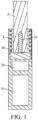
- the susceptor during use forms the chamber that is configured to receive the aerosol generation product A, and the susceptor generates an aerosol for inhalation by heating an outer periphery of the aerosol generation product A.
- the susceptor may alternatively be made of stainless steel of grade 420 (SS420) and an alloy material containing iron/nickel (such as permalloy).
- the aerosol generating device further includes a holder 40 that is configured to dispose the inductor L and the susceptor 30, and a material of the holder 40 may include a non-metal material with high temperature resistance, such as PEEK, ceramic, or the like.
- a material of the holder 40 may include a non-metal material with high temperature resistance, such as PEEK, ceramic, or the like.
- the inductor L is fixed by being wound on an outer wall of the holder 40.
- the holder 40 has a hollow tubular shape, and a portion of the tubular hollow space forms the chamber that is configured to receive the aerosol generation product A.
- the susceptor 30 is made of the foregoing susceptible materials, or is obtained by electroplating or depositing to form a susceptible material coating on an outer surface of a ceramic or another heat-resistant base material.
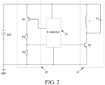
- a structure and basic components of the circuit 20 may be shown in FIG. 2 and FIG. 3 , including: an inverter 21, including a switch circuit 211 and a resonant circuit 212.
- the switch circuit 211 includes a transistor Q1; and the resonant circuit 212 is formed by connecting a capacitor C1 with the inductor L in parallel, thereby forming a parallel LC resonant circuit.
- the transistor Q1 is alternately turned on and turned off under driving of a pulse signal, to guide a current between the battery cell 10 and the resonant circuit 212 to make the resonant circuit 212 to resonate, so as to form an alternating current flowing through the inductor L, thereby making the inductor L to generate a varying magnetic field to induce the susceptor 30 to generate heat.
- the transistor Q1 is a commonly used MOS tube, where the MOS tube is turned on or turned off based on a PWM pulse signal received by a gate.
- a frequency of the PWM pulse signal ranges from 80 KHz to 400 KHz; and more specifically, the frequency may approximately range from 200 KHz to 300 KHz.
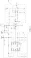
- turn-on or turn-off of the switch circuit 211 is controlled by a PWM pulse signal generated by a driver 23, and the driver 23 includes a drive chip U1 and a peripheral circuit thereof.
- the driver 23 is generated based on a PWM pulse control signal generated by a controller 22.
- the PWM pulse signal may alternatively be generated by a driver that is integrated in the controller 22.
- turn-on time and turn-off time of the transistor Q1 are different, that is, a duty ratio of the PWM pulse signal is not 50%, and a resonance process of the resonant circuit 212 is asymmetric, so that the resonant circuit 212 maintains a sufficient resonance voltage to maintain a strength of the magnetic field.
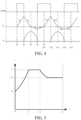
- FIG. 4 shows a change process of a resonant current/voltage in a cycle from t1 to t5 driven by the resonant circuit 212 of the circuit 20 shown in FIG. 3 in a symmetrical resonant manner with a duty ratio of 50%.
- the process includes:
- a voltage formed between a drain and a source of the MOS tube Q1 is actually a sum of a reverse pulse peak voltage and a voltage outputted by the positive pole of the battery cell 10.
- the capacitor C1 is discharged through the inductor L until discharging is completed, i3 reaches a maximum value, and a voltage at the both ends of the capacitor C1 gradually decreases until disappears. At this moment, all the electrical energy in the capacitor C1 is converted into magnetic energy in the inductor L. Similarly, due to the inductive reactance, the current flowing through the inductor L gradually changes in a direction opposite to the directions in S1 and S2. The capacitor C1 discharges until an electromotive force at the both ends of the inductor L is reversed.
- a synchronous detection unit 24 is configured to detect a resonance voltage of the resonant circuit 212.
- the synchronous detection unit 24 mainly includes a zero crossing comparator U2, where the zero crossing comparator U2 is configured to take a sample and detect a zero crossing point of a drain voltage signal of the MOS tube Q1, so that only the controller 22 controls switching of the MOS tube Q1 between tum-on/tum-off based on a zero crossing moment.
- the embodiment shown in FIG. 2 further proposes to detect a real-time voltage of the battery cell 10 to control a voltage detection circuit 25 of the transistor Q1, where the voltage detection circuit 25 includes a controllable switch tube Q2, a voltage dividing resistor R1, and a voltage dividing resistor R2. Under the action of a control signal of the controller 22, the controllable switch tube Q2 may turn on or turn off the voltage detection circuit 25.
- the controller 22 may adjust a duty ratio and/or a frequency of the PWM pulse signal outputted to the MOS tube Q1. If a detected real-time voltage of the battery cell 10 is relatively low, the duty ratio of the PWM pulse signal may be increased and/or the frequency of the PWM pulse signal may be reduced. If a detected real-time voltage of the battery cell 10 is relatively high, the duty ratio of the PWM pulse signal may be reduced and/or the frequency of the PWM pulse signal may be increased. In a specific implementation, a correlation table of the real-time voltage of the battery cell 10 and the duty ratio of the PWM pulse signal and/or the frequency of the PWM pulse signal may be established in advance.
- the duty ratio of the PWM pulse signal and/or the frequency of the PWM pulse signal may be determined by looking up the table, so that the controller 22 controls the PWM pulse signal based on a determined duty ratio and/or frequency.
- the duty ratio and/or the frequency of the PWM pulse signal is adjusted based on the real-time voltage of the battery cell 10.
- the first preset voltage threshold is slightly lower than a maximum operating voltage of the battery cell 10. Taking 4.2 V as an example, the first preset voltage threshold may be set to 4.1 V.
- the controller 22 is configured to drive, if the real-time voltage of the battery cell 10 is less than or equal to a second preset voltage threshold, the transistor Q1 to be alternately turned on and turned off based on a duty ratio and/or a frequency of a pulse signal that is corresponding to the second preset voltage threshold, where the second preset voltage threshold is less than the first preset voltage threshold.
- the transistor Q1 is driven to be alternately turned on and turned off based on the duty ratio and/or the frequency of the pulse signal corresponding to the second preset voltage threshold.
- the second preset voltage threshold ranges from 3 V to 3.6 V; or ranges from 3.1 V to 3.6 V; or ranges from 3.2 V to 3.6 V; or ranges from 3.3 V to 3.6 V; or ranges from 3.3 V to 3.5 V.
- the second preset voltage threshold is set to 3.4 V.
- the duty ratio and/or the frequency of the pulse signal corresponding to the second preset voltage threshold may be preset or obtained through looking up the foregoing table.
- the controller 22 is configured to adjust, if a difference between two consecutive real-time voltages of the battery cell 10 is greater than or equal to a preset difference threshold, the duty ratio and/or the frequency of the PWM pulse signal based on the current real-time voltage of the battery cell 10.
- the controller 22 controls the PWM pulse signal based on the determined duty ratio and/or frequency.
- the preset difference threshold is set to 0.1 V.
- the controller 22 is configured to adjust the duty ratio and/or the frequency of the PWM pulse signal based on the real-time voltage of the battery cell 10 during a period of controlling the susceptor 30 to rise from an initial temperature to a preset temperature.
- a real-time temperature of the susceptor 30 may be obtained by a temperature sensor (not shown in the figure) that is disposed in the aerosol generating device, so that the controller 22 may control the susceptor 30 to rise from the initial temperature to the preset temperature.
- the preset temperature may be an optimal temperature for an inhalable material to generate an aerosol, in other words, the inhalable material can provide a vapor volume and a temperature that are the most suitable for a user to inhale and taste better at the temperature.
- the preset temperature ranges from 150°C to 350°C; or ranges from 180°C to 350°C; or ranges from 220°C to 350°C; or ranges from 220°C to 300°C; or ranges from 220°C to 280°C; or ranges from 220°C to 260°C.
- driving the transistor Q1 with a same duty ratio and/or frequency may cause inconsistent time for the susceptor 30 to rise from the initial temperature to the preset temperature.
- a difference between time for the susceptor 30 to rise from the initial temperature to the preset temperature ranges from 7s to 8s, affecting the inhalation experience of the user. Therefore, during this period, based on the real-time voltage of the battery cell 10, the duty ratio and/or the frequency of the PWM pulse signal are adjusted, so that the time for the susceptor to rise from the initial temperature to the preset temperature may be consistent, and the inhalation experience of the user is also better.
- the duty ratio and/or the frequency of the PWM pulse signal are adjusted based on the real-time voltage of the battery cell 10. Otherwise, the duty ratio and/or the frequency of the PWM pulse signal may not be adjusted.
- the controller controls to output a pulse voltage of a first duty ratio; and when a second voltage value of the battery cell 10 that is less than the first voltage value is received, the controller controls to output a pulse voltage of a second duty ratio, where the first duty ratio is less than the second duty ratio; or when a first voltage value of the battery cell 10 is received, the controller controls to output a pulse voltage of a first frequency, and when a second voltage value of the battery cell 10 that is less than the first voltage value is received, the controller controls to output a pulse voltage of a second frequency, where the first frequency is greater than the second frequency.
- the controller 22 is configured to control to output a pulse voltage of a first duty ratio or a first frequency when the received voltage value of the real-time voltage of the battery cell 10 is within a first interval, and control to output a pulse voltage of a second duty ratio or a second frequency when the received voltage value of the real-time voltage of the battery cell 10 is within a second interval that is different from the first interval.
- FIG. 5 is a schematic diagram of a temperature curve of a susceptor 30 according to an implementation of this application.
- a horizontal coordinate t of the temperature curve represents time, and a vertical coordinate T represents a temperature. Specifically, at the moment t0, an initial temperature of the susceptor 30 is T0.
- a controller 22 controls heating power of the susceptor 30 to heat at full power of the battery cell 10.
- the susceptor 30 is heated to a target temperature T1, for example, 250°C.
- the controller 22 obtains a real-time temperature of the susceptor 30 through a temperature sensor and obtains a real-time voltage of the battery cell 10 through a voltage detection circuit 25 at intervals; if the real-time temperature of the susceptor 30 is lower than a preset temperature threshold, adjusts a duty ratio and/or a frequency of a PWM pulse signal based on the real-time voltage of the battery cell 10; and if the real-time temperature of the susceptor 30 is not lower than the preset temperature threshold, continues to obtain the real-time temperature of susceptor 30 and the real-time voltage of the battery cell 10.
- the controller 22 controls electrical power provided by the battery cell 10 to the susceptor 30 and controls the susceptor 30 to maintain at the target temperature T1 (250°C) for a period of time (that is, the time period from t1 to t2).
- the controller 22 may output a prompt signal for inhaling an aerosol, to prompt the user to inhale the aerosol.
- the controller 22 controls heating power provided by the battery cell 10 to the susceptor 30 and controls the temperature of the susceptor 30 to decrease from T1 (250°C) to T2 (for example, 200°C). Subsequently, the controller 22 controls the electrical power provided by the battery cell 10 to the susceptor 30, to control the susceptor 30 to maintain at T2 for a period of time.
Landscapes
- Engineering & Computer Science (AREA)
- Physics & Mathematics (AREA)
- Electromagnetism (AREA)
- Manufacturing & Machinery (AREA)
- Chemical & Material Sciences (AREA)
- Chemical Kinetics & Catalysis (AREA)
- Electrochemistry (AREA)
- General Chemical & Material Sciences (AREA)
- Microelectronics & Electronic Packaging (AREA)
- Power Engineering (AREA)
- Secondary Cells (AREA)
Applications Claiming Priority (2)
| Application Number | Priority Date | Filing Date | Title |
|---|---|---|---|
| CN202111024657.8A CN115736387A (zh) | 2021-09-02 | 2021-09-02 | 气溶胶生成装置及其控制方法 |
| PCT/CN2022/116326 WO2023030411A1 (zh) | 2021-09-02 | 2022-08-31 | 气溶胶生成装置及其控制方法 |
Publications (2)
| Publication Number | Publication Date |
|---|---|
| EP4397201A1 true EP4397201A1 (de) | 2024-07-10 |
| EP4397201A4 EP4397201A4 (de) | 2024-12-18 |
Family
ID=85332076
Family Applications (1)
| Application Number | Title | Priority Date | Filing Date |
|---|---|---|---|
| EP22863546.2A Pending EP4397201A4 (de) | 2021-09-02 | 2022-08-31 | Aerosolerzeugungsvorrichtung und steuerungsverfahren dafür |
Country Status (4)
| Country | Link |
|---|---|
| US (1) | US20240365881A1 (de) |
| EP (1) | EP4397201A4 (de) |
| CN (1) | CN115736387A (de) |
| WO (1) | WO2023030411A1 (de) |
Families Citing this family (6)
| Publication number | Priority date | Publication date | Assignee | Title |
|---|---|---|---|---|
| CN116210982A (zh) * | 2023-03-31 | 2023-06-06 | 上海烟草集团有限责任公司 | 加热电路、加热控制方法及气溶胶产生装置 |
| CN116439427A (zh) * | 2023-05-11 | 2023-07-18 | 深圳市合元科技有限公司 | 气溶胶生成装置的控制方法和气溶胶生成装置 |
| CN119423401A (zh) * | 2023-07-28 | 2025-02-14 | 深圳市合元科技有限公司 | 一种控制方法及气溶胶生成装置 |
| WO2025039946A1 (zh) * | 2023-08-18 | 2025-02-27 | 深圳市合元科技有限公司 | 电子雾化装置及其控制方法 |
| CN120284021A (zh) * | 2024-01-10 | 2025-07-11 | 深圳市合元科技有限公司 | 气溶胶生成装置及其控制方法 |
| CN120284015A (zh) * | 2024-01-10 | 2025-07-11 | 深圳市合元科技有限公司 | 气溶胶生成装置及操作方法 |
Family Cites Families (13)
| Publication number | Priority date | Publication date | Assignee | Title |
|---|---|---|---|---|
| JPH11243327A (ja) * | 1998-02-25 | 1999-09-07 | Hitachi Ltd | パルスデューティ補正回路 |
| US8427123B2 (en) * | 2009-07-08 | 2013-04-23 | Microchip Technology Incorporated | System, method and apparatus to transition between pulse width modulation and pulse-frequency modulation in a switch mode power supply |
| WO2013128808A1 (ja) * | 2012-02-29 | 2013-09-06 | Necエナジーデバイス株式会社 | 電池制御システム、電池パック、電子機器および充電機器 |
| TWI692274B (zh) * | 2014-05-21 | 2020-04-21 | 瑞士商菲利浦莫里斯製品股份有限公司 | 用於加熱氣溶膠形成基材之感應加熱裝置及操作感應加熱系統之方法 |
| WO2017085242A1 (en) * | 2015-11-19 | 2017-05-26 | Philip Morris Products S.A. | Inductive heating device for heating an aerosol-forming substrate |
| KR20240093887A (ko) * | 2017-03-14 | 2024-06-24 | 필립모리스 프로덕츠 에스.에이. | 배터리 동력식 에어로졸 발생 장치용 전력 관리 방법 및 시스템 |
| GB201705206D0 (en) * | 2017-03-31 | 2017-05-17 | British American Tobacco Investments Ltd | Apparatus for a resonance circuit |
| CN108563152B (zh) * | 2018-06-04 | 2024-07-19 | 深圳市海派特光伏科技有限公司 | Asic集成电路、电子烟的控制电路及其控制方法 |
| CN110122927A (zh) * | 2019-04-03 | 2019-08-16 | 深圳市合元科技有限公司 | 电加热发烟系统及挥发性化合物的释放控制方法 |
| CN110547514A (zh) * | 2019-09-16 | 2019-12-10 | 深圳雾芯科技有限公司 | 一种雾化装置 |
| CN112806618B (zh) * | 2019-10-31 | 2023-06-16 | 深圳市合元科技有限公司 | 气雾生成装置及控制方法 |
| CN112741375B (zh) * | 2019-10-31 | 2024-05-03 | 深圳市合元科技有限公司 | 气雾生成装置及控制方法 |
| CN112806610B (zh) * | 2019-11-15 | 2024-05-03 | 深圳市合元科技有限公司 | 气雾生成装置及控制方法 |
-
2021
- 2021-09-02 CN CN202111024657.8A patent/CN115736387A/zh active Pending
-
2022
- 2022-08-31 EP EP22863546.2A patent/EP4397201A4/de active Pending
- 2022-08-31 US US18/687,326 patent/US20240365881A1/en active Pending
- 2022-08-31 WO PCT/CN2022/116326 patent/WO2023030411A1/zh not_active Ceased
Also Published As
| Publication number | Publication date |
|---|---|
| CN115736387A (zh) | 2023-03-07 |
| US20240365881A1 (en) | 2024-11-07 |
| WO2023030411A1 (zh) | 2023-03-09 |
| EP4397201A4 (de) | 2024-12-18 |
Similar Documents
| Publication | Publication Date | Title |
|---|---|---|
| EP4397201A1 (de) | Aerosolerzeugungsvorrichtung und steuerungsverfahren dafür | |
| US12426635B2 (en) | Apparatus for aerosol generating device | |
| EP4052597A1 (de) | Vorrichtung zur erzeugung von aerosolen und verfahren zur steuerung | |
| EP4260737A1 (de) | Aerosolerzeugungsvorrichtung | |
| US20240099376A1 (en) | Aerosol-producing apparatus and control method therefor | |
| JP7669491B6 (ja) | エアロゾル発生装置及び制御方法 | |
| CN112741375B (zh) | 气雾生成装置及控制方法 | |
| US20220183390A1 (en) | Aerosol provision device | |
| WO2022017418A1 (zh) | 气雾生成装置 | |
| CN115005511A (zh) | 气雾生成装置及控制方法 | |
| CN116406866A (zh) | 气溶胶生成装置及其控制方法 | |
| WO2025039946A1 (zh) | 电子雾化装置及其控制方法 | |
| CN119423405A (zh) | 电子雾化装置及其控制方法 | |
| EP4537686A1 (de) | Stromversorgungsanordnung und elektronische zerstäubungsvorrichtung und steuerungsverfahren dafür | |
| CN118614658A (zh) | 气溶胶生成装置及气溶胶生成装置的控制方法 |
Legal Events
| Date | Code | Title | Description |
|---|---|---|---|
| STAA | Information on the status of an ep patent application or granted ep patent |
Free format text: STATUS: THE INTERNATIONAL PUBLICATION HAS BEEN MADE |
|
| PUAI | Public reference made under article 153(3) epc to a published international application that has entered the european phase |
Free format text: ORIGINAL CODE: 0009012 |
|
| STAA | Information on the status of an ep patent application or granted ep patent |
Free format text: STATUS: REQUEST FOR EXAMINATION WAS MADE |
|
| 17P | Request for examination filed |
Effective date: 20240321 |
|
| AK | Designated contracting states |
Kind code of ref document: A1 Designated state(s): AL AT BE BG CH CY CZ DE DK EE ES FI FR GB GR HR HU IE IS IT LI LT LU LV MC MK MT NL NO PL PT RO RS SE SI SK SM TR |
|
| STAA | Information on the status of an ep patent application or granted ep patent |
Free format text: STATUS: EXAMINATION IS IN PROGRESS |
|
| DAV | Request for validation of the european patent (deleted) | ||
| DAX | Request for extension of the european patent (deleted) | ||
| A4 | Supplementary search report drawn up and despatched |
Effective date: 20241114 |
|
| RIC1 | Information provided on ipc code assigned before grant |
Ipc: A24F 40/57 20200101ALI20241108BHEP Ipc: A24F 40/50 20200101ALI20241108BHEP Ipc: A24F 40/465 20200101ALI20241108BHEP Ipc: A24F 40/40 20200101ALI20241108BHEP Ipc: A24F 40/20 20200101ALI20241108BHEP Ipc: H02J 7/00 20060101ALI20241108BHEP Ipc: A24F 40/51 20200101ALI20241108BHEP Ipc: A24F 47/00 20200101AFI20241108BHEP |
|
| 17Q | First examination report despatched |
Effective date: 20241127 |