EP4396423B1 - Geländersystem, verfahren zur montage eines geländersystems und verwendung eines geländersystems - Google Patents
Geländersystem, verfahren zur montage eines geländersystems und verwendung eines geländersystems Download PDFInfo
- Publication number
- EP4396423B1 EP4396423B1 EP21777948.7A EP21777948A EP4396423B1 EP 4396423 B1 EP4396423 B1 EP 4396423B1 EP 21777948 A EP21777948 A EP 21777948A EP 4396423 B1 EP4396423 B1 EP 4396423B1
- Authority
- EP
- European Patent Office
- Prior art keywords
- rail
- pin part
- collar
- balusters
- bolt means
- Prior art date
- Legal status (The legal status is an assumption and is not a legal conclusion. Google has not performed a legal analysis and makes no representation as to the accuracy of the status listed.)
- Active
Links
Images

Classifications
-
- E—FIXED CONSTRUCTIONS
- E04—BUILDING
- E04F—FINISHING WORK ON BUILDINGS, e.g. STAIRS, FLOORS
- E04F11/00—Stairways, ramps, or like structures; Balustrades; Handrails
- E04F11/18—Balustrades; Handrails
- E04F11/181—Balustrades
- E04F11/1817—Connections therefor
-
- B—PERFORMING OPERATIONS; TRANSPORTING
- B63—SHIPS OR OTHER WATERBORNE VESSELS; RELATED EQUIPMENT
- B63B—SHIPS OR OTHER WATERBORNE VESSELS; EQUIPMENT FOR SHIPPING
- B63B35/00—Vessels or similar floating structures specially adapted for specific purposes and not otherwise provided for
- B63B35/44—Floating buildings, stores, drilling platforms, or workshops, e.g. carrying water-oil separating devices
-
- E—FIXED CONSTRUCTIONS
- E04—BUILDING
- E04F—FINISHING WORK ON BUILDINGS, e.g. STAIRS, FLOORS
- E04F11/00—Stairways, ramps, or like structures; Balustrades; Handrails
- E04F11/18—Balustrades; Handrails
- E04F11/181—Balustrades
- E04F11/1812—Details of anchoring to the wall or floor
-
- E—FIXED CONSTRUCTIONS
- E04—BUILDING
- E04F—FINISHING WORK ON BUILDINGS, e.g. STAIRS, FLOORS
- E04F11/00—Stairways, ramps, or like structures; Balustrades; Handrails
- E04F11/18—Balustrades; Handrails
- E04F11/181—Balustrades
- E04F11/1842—Balusters; Grille-type elements
-
- F—MECHANICAL ENGINEERING; LIGHTING; HEATING; WEAPONS; BLASTING
- F16—ENGINEERING ELEMENTS AND UNITS; GENERAL MEASURES FOR PRODUCING AND MAINTAINING EFFECTIVE FUNCTIONING OF MACHINES OR INSTALLATIONS; THERMAL INSULATION IN GENERAL
- F16B—DEVICES FOR FASTENING OR SECURING CONSTRUCTIONAL ELEMENTS OR MACHINE PARTS TOGETHER, e.g. NAILS, BOLTS, CIRCLIPS, CLAMPS, CLIPS OR WEDGES; JOINTS OR JOINTING
- F16B19/00—Bolts without screw-thread; Pins, including deformable elements; Rivets
- F16B19/04—Rivets; Spigots or the like fastened by riveting
- F16B19/05—Bolts fastening by swaged-on collars
-
- F—MECHANICAL ENGINEERING; LIGHTING; HEATING; WEAPONS; BLASTING
- F16—ENGINEERING ELEMENTS AND UNITS; GENERAL MEASURES FOR PRODUCING AND MAINTAINING EFFECTIVE FUNCTIONING OF MACHINES OR INSTALLATIONS; THERMAL INSULATION IN GENERAL
- F16B—DEVICES FOR FASTENING OR SECURING CONSTRUCTIONAL ELEMENTS OR MACHINE PARTS TOGETHER, e.g. NAILS, BOLTS, CIRCLIPS, CLAMPS, CLIPS OR WEDGES; JOINTS OR JOINTING
- F16B7/00—Connections of rods or tubes, e.g. of non-circular section, mutually, including resilient connections
-
- E—FIXED CONSTRUCTIONS
- E04—BUILDING
- E04F—FINISHING WORK ON BUILDINGS, e.g. STAIRS, FLOORS
- E04F11/00—Stairways, ramps, or like structures; Balustrades; Handrails
- E04F11/18—Balustrades; Handrails
- E04F11/181—Balustrades
- E04F11/1817—Connections therefor
- E04F2011/1819—Connections therefor between balustrade posts and horizontal or sloping balustrade members
-
- E—FIXED CONSTRUCTIONS
- E04—BUILDING
- E04F—FINISHING WORK ON BUILDINGS, e.g. STAIRS, FLOORS
- E04F11/00—Stairways, ramps, or like structures; Balustrades; Handrails
- E04F11/18—Balustrades; Handrails
- E04F2011/1868—Miscellaneous features of handrails not otherwise provided for
- E04F2011/1872—Miscellaneous features of handrails not otherwise provided for illuminated
-
- E—FIXED CONSTRUCTIONS
- E04—BUILDING
- E04F—FINISHING WORK ON BUILDINGS, e.g. STAIRS, FLOORS
- E04F11/00—Stairways, ramps, or like structures; Balustrades; Handrails
- E04F11/18—Balustrades; Handrails
- E04F2011/1885—Handrails or balusters characterized by the use of specific materials
- E04F2011/1889—Handrails or balusters characterized by the use of specific materials mainly of metal
-
- Y—GENERAL TAGGING OF NEW TECHNOLOGICAL DEVELOPMENTS; GENERAL TAGGING OF CROSS-SECTIONAL TECHNOLOGIES SPANNING OVER SEVERAL SECTIONS OF THE IPC; TECHNICAL SUBJECTS COVERED BY FORMER USPC CROSS-REFERENCE ART COLLECTIONS [XRACs] AND DIGESTS
- Y02—TECHNOLOGIES OR APPLICATIONS FOR MITIGATION OR ADAPTATION AGAINST CLIMATE CHANGE
- Y02E—REDUCTION OF GREENHOUSE GAS [GHG] EMISSIONS, RELATED TO ENERGY GENERATION, TRANSMISSION OR DISTRIBUTION
- Y02E10/00—Energy generation through renewable energy sources
- Y02E10/70—Wind energy
- Y02E10/727—Offshore wind turbines
Definitions
- the invention relates to a railing system for an offshore installation, wherein the railing system comprises two or more balusters and at least one rail.
- the invention also relates to a method for assembling a railing system on an offshore installation and use of a winch system.
- offshore installations such as oil rigs, offshore wind turbines, wave energy plants and other it is important that all platforms, decks, gangways etc. are provided with railing to prevent personnel from falling off the installation and to provide something to hold on to when moving around in bad weather.
- An object of the invention is therefore to provide for an advantageous technique for forming a railing system for an offshore installation.
- the invention provides for a railing system for an offshore installation.
- the railing system comprises two or more balusters including connection means for connecting the balusters to the offshore installation and at least one rail comprising two or more longitudinal rail sides, wherein at least one of the two or more longitudinal rail sides is a T-slot side comprising at least one T-slot.
- the railing system also comprises at least two fixation devices arranged to connect the at least one rail to the two or more balusters so that the T-slot side of the rail is forced against a first side of the balusters
- each of the at least two fixation devices comprises bolt means including a pin part and a head part, wherein the head part is arranged at one end of the pin part, wherein the head part is arranged in the at least one T-slot and the pin part is extending through an orifice in the baluster
- the fixation device further comprise a collar encircling the pin part on a second side of the balusters, wherein the first side is opposite the second side, wherein the collar is connected to the pin part by means of a compression joint, and wherein the two or more balusters, the at least one rail and the at least two fixation devices are made of aluminium.
- Assembling the railing by means of fixation devices is advantageous in that this enables that welding can be avoided which in turn means that the railing parts can be transported disassembled to the erection site - thereby reducing transportation cost.
- connection means is to be understood as any kind of connector or part of a connector suited for connecting the balusters to the offshore installation.
- the term includes any kind of bolt holes or holes for other devices suited for the purpose, any kind of clamps, any kind of treaded pins, hooks or other.
- bolt means is to be understood as any kind of threadless bolt having a pin part with a head part arranged at one end of the pin part, wherein the head part has a larger diameter or cross-sectional extent than the pin part as seen in the longitudinal direction of the bolt means.
- the term includes any kind of pin with a larger head a one end of the pin, any kind of nail like device, any kind of rod being larger at one end or other.
- compression joint is to be understood as any kind of connection formed by one part of the compression joint being compressed so that it permanently deforms and connects to another part of the compression joint through interlocking geometry or friction.
- a compression joint is an irreversible joint type in which the joint parts can only be separated again by destroying at least one of the joint parts.
- the collar is compressed around the pin part so that the collar is permanently deformed and squeezes around the pin part to lock the collar against displacement in relation to the pin part and so that the collar can only be removed again by sawing the collar of or pulling the collar of by used of extensive force - thus, destroying the collar and/or the pin part.
- the at least one T-slot can extend the entire length of the at least one rail.
- Forming the T-slot so that it is extending the entire length of the rail is advantageous in that it makes the system more versatile, it enables that the bolt means may be slid into the T-slot from both ends of the rail and in that it enables that the rail may be manufactured by extrusion, which is inexpensive and efficient.
- the at least one T-slot is arranged in a first longitudinal rail side of the two or more longitudinal rail sides and wherein an additional T-slot is arranged in a second longitudinal rail side of the two or more longitudinal rail sides.
- Forming the rail with an additional T-slot is advantageous in that additional features, fitting, equipment and other hereby easily can be connected to the rail in a simple and versatile manner.
- Illumination means can be arranged in the additional T-slot.
- Railing on an offshore installation is almost always placed at the outer edge of a platform or the like and it is therefore very dangerous if personnel somehow pass the railing by mistake. It is therefore advantageous to arrange illumination means in the additional T-slot both to guide the personnel to the railing to provide something secure to hold on to in rough weather and to light up the at least the periphery of the platform. Furthermore, placing the illumination means in the additional T-slot is advantageous in that this prevents straps, clothes or other from getting caught on the illumination means and the illumination means is better protected.
- illumination means is to be understood as any kind of light or illuminator.
- the term includes any kind of lamp, spot, light emitting diode, incandescent bulb, halogen or other or any combination thereof or any other kind of light emitter.
- the first longitudinal rail side is neighbouring the second longitudinal rail side.
- the first longitudinal rail side includes the T-slot and therefore faces the baluster.
- the second longitudinal rail side bordering on the first longitudinal rail side - e.g. so that the second longitudinal rail side is substantially perpendicular to the first longitudinal rail side - it is easier to retrofit additional features, fitting, equipment and other in the additional T-slot and to e.g. make illumination means arranged in the additional T-slot illuminate below and in front of the railing.
- the additional T-slot can extend the entire length of the at least one rail.
- Forming the additional T-slot so that it is extending the entire length of the rail is advantageous in that it makes the system more versatile, it enables that the bolt means, fittings, equipment, connectors or other may be slid into the additional T-slot from both ends of the rail and in that it enables that the rail may be manufactured by extrusion, which is inexpensive and efficient.
- the pin part is cylindrical and wherein a cylindrical surface of the pin part comprises a number of indentations.
- Forming the cylindrical surface of the pin part with indentations is advantageous in that when the compression joint is formed by compressing the collar around the pin part, the collar will deform into the indentations and thereby form interlocking geometry when viewed in the longitudinal direction of the pin.
- the indentations are formed between a number of radial circular prostitutions along the lengthwise extent of the pin part.
- Forming the indentations as the valleys formed between radial circular prostitutions along the lengthwise - i.e. longitudinal - extent of the pin part is advantageous in that this ensures a strong hold when the compression joint is formed, and it ensures an evenly distributed hold all around the pin part.
- the pin part has a corrugated surface forming a number of ridges and valleys along the lengthwise extent of the pin part.
- Forming the indentations as the valleys of a corrugated surface is advantageous in that this ensures a strong hold when the compression joint is formed, and it ensures an evenly distributed hold all around the pin part.
- the term "along the lengthwise extent of the pin part” is to be understood as at least a part of the lengthwise extent of the pin part. I.e. the radial circular prostitutions and/or the corrugated surface does not have to extend the entire lengthwise extent of the pin part.
- the compression joint can include the collar protruding into the indentations.
- Forming the compression joint so that parts of the collar is protruding into the indentations is advantageous in that this will form interlocking geometry that will provide a very strong hold that is unaffected by vibration.
- connection means are arranged at a first longitudinal baluster end of the two or more balusters.
- connection means at one end of each of the balusters is advantageous in that reduces material use and ensures that the balusters can be connected so that they project upwards e.g. perpendicular to the upper surface of the offshore installation to which they are attached.
- the at least one rail comprises a handrail arranged at a second longitudinal baluster end of the two or more balusters, wherein the second longitudinal baluster end is opposite the first longitudinal baluster end.
- the railing system further comprises a mid-rail connected to the two or more balusters between the connection means and the handrail by means of at least two fixation devices of the at least two fixation devices.
- Placing the handrail at the top of the balusters is advantageous in that it makes it easier to reach and use the handrail and it reduces the risk of straps, clothes or other being caught on protruding upper ends of the balusters.
- Providing a mid-rail between the connection means and the handrail is advantageous in that this will enable that the handrail may be arranged at a suitable hight without risking personal falling of the offshore installation by falling under the handrail.
- connecting the mid-rail to the balusters by means of fixation devices is advantageous in that this enables that welding can be avoided, it is easy to e.g. change the distance between balusters on site and using fixation devices forming connections by means of compression joints is advantageous in that by compressing the collar around the pin part the assembly process cannot be reversed and the fixation devices will therefore not disassemble over time due to vibrations.
- the handrail and the mid-rail can be parallel.
- Forming the handrail and the mid-rail parallel is advantageous in that it makes it easier to comply with rules and regulations regarding railing design offshore and it makes it easier to connect fittings, equipment, posts and other to both the handrail and the mid-rail.
- the railing system further comprises
- Covering the open ends of the handrail and the mid-rail is advantageous in that this will reduce the risk of ingress of water, dirt and other which over time could lead to deterioration of the rails or lead to hygiene problems. And by making the end covers extend between the handrail and the mid-rail at each end the risk of straps, clothes or other being caught on the free ends is reduced.
- the at least one rail is connected to the two or more balusters so that the longitudinal extent of the at least one rail is substantially perpendicular to the longitudinal extent of the two or more balusters.
- the compression joint comprises the collar and the pin part having interlocking geometry interlocking the collar and the pin part against displacement in the longitudinal direction of the pin part.
- the invention also provides for a method for assembling a railing system according to any of the previously discussed railing systems on an offshore installation, the method comprising the steps of:
- Assembling the railing system on site is advantageous in that it simplifies and reduces cost of transportation. And connecting the rails to the balusters by means bolt means in T-slots in the rails ensures a flexible and versatile assembly method. Furthermore, by connecting the collar to the pin part of the bolt means by means of a compression joint is advantageous in that it is a fast and efficient way of connecting the rail to the balusters that will ensure that the connection is not loosened or undone by vibrations. And making all the parts in aluminium is advantageous in that the risk of galvanic corrosion is reduced.
- the pin part of the first and second bolt means is pulled in a direction away from the second side and the first and second collar is pushed against the second side while the compression joint is formed.
- Pulling the pin part away from the baluster while pushing the collar against the baluster when the compression joint is formed by squeezing the collar firmly and tightly around the pin part is advantageous in that this will ensure that the rail is held firmly against the baluster after the compression joint is formed.
- squeezing the first collar against the pin part of the first bolt means causes the first collar to deform radially into indentations in the pin part of the first bolt means and wherein squeezing the second collar against the pin part of the second bolt means causes the second collar to deform radially into indentations in the pin part of the second bolt means.
- the method further comprises sliding the first and second bolt means to positions in the T-slot where the distance between the first and second bolt means is the same as the distance between the first and second baluster of the two or more balusters after placing the head part of first and second aluminium bolt means in the T-slot.
- the method can be performed by means of a railing system according to any of the previously discussed railing systems.
- the invention provides for use of a railing system according to any of the previously discussed railing systems on a transition piece arranged between a foundation and a tower of an offshore wind turbine.
- transition piece arranged between the foundation - such as a monopile, tripod, jacket or similar foundation - and the wind turbine tower.
- Such transitions pieces are located just above sea level and therefore exposed to seawater, waves, rough weather and on top of that significant vibrations from the wind turbine. It is therefore particularly advantageous to use a railing system according to the present invention on such a transition piece.
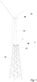
- Fig. 1 illustrates an offshore wind turbine 36 comprising a railing system 1, as seen in perspective.
- the railing system 1 is arranged on an offshore installation 2 in the form of a transition piece 33 located between a foundation 34 - in this case a jacket foundation - and the tower 35 of an offshore wind turbine 36.
- the railing system 1 is arranged along the outer periphery of the upper platform formed on the upper surface of the transition piece 33.
- the transition piece 33 is usually located just above sea level and can therefore be hit by waves in rough weather.
- the transition piece 33 is shown very simplified and usually the transition piece 33 can also comprises stairs, boat landings, helipads, additional platforms or other that could comprise railing system 1 according to the present invention.
- the railing system 1 could be mounted on an oil rig, an offshore energy conversion plant, an offshore oil refinery or another type of offshore installation 2.
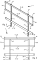
- Fig. 2 illustrates a section of a railing system 1, as seen from in perspective
- fig. 3 illustrates a section of a railing system 1, as seen from the front.
- the railing system 1 comprises two balusters 3 - i.e., two vertical or substantially vertical posts, poles or supports - to which three rails 11 has been connected.
- the rails 11 comprises an upper handrail 26 arranged at an upper end of the baluster 3 - i.e. a second longitudinal baluster end 27 -, a lower kickplate 37 (also called a kick rail) arranged near the lower end of the baluster 3 - i.e., a first longitudinal baluster end 25 -, and a mid-rial 28 arranged between the upper handrail 26 and the lower kickplate 37.
- the railing system 1 could comprise further rails 11 - such as four, five, six or even more rails 11 - or the railing system 1 could comprise fewer rails 11 such as only the handrail 26 and the mid-rial 28 or kickplate 37 or only the handrail 26.
- the railing system 1 could comprise three, four, six or even more balusters 3 and/or some rails 11 could be connected to only some of the balusters 3.
- all the rails 11 and all the balusters 3 are made fully of aluminum but in another embodiment a additional surface coating - such as a rubber coating, surface paint or other could be provided to one or more of the railing system parts 3, 8 (see fig. 5 ), 11.
- the balusters 3 each comprise connection means 4 in the form of through holes by means of which the first longitudinal baluster end 25 can be connected to an outside vertical surface of the offshore installation 2 by use of bolts or the like.
- connection means 4 could also or instead include a foot plate for connecting the balusters 2 to a horizontal surface
- connection means 4 could also or instead include threaded holes, threaded studs, claps or other.
- balusters 3 are made from an angle aluminium profile but in another embodiment the balusters 3 could be made from pipes, rods, T-profiles, slotted profiles or other.
- the handrail 26, the mid-rail 28 and the kickplate 37 are parallel and mounted so that the longitudinal extent of the rails 11, 26, 28, 37 are substantially perpendicular to the longitudinal extent of the balusters 3.
- two or more of the rails 11 would not be parallel and/or one or more of the rails 11 would not be perpendicular to the balusters 3 - e.g. when the railing system 1 is used as a stair railing.
- the railing system 1 further comprises a first end cover 29 covering the first longitudinal rail ends 30 of the handrail 26 and the mid-rail 28 and a second end cover 31 covering the second longitudinal rail ends 32 of the handrail 26 and the mid-rail 28.
- first end cover 29 and the second end cover 31 also extend vertically between the rail ends 30, 32 but in another embodiment each rail end 30, 32 could comprise individual end covers 29, 31 - i.e. in another embodiment the railing system 1 could comprise four end covers 29, 31.
- the end covers 29, 31 are connected to the rails 26, 28 by means of screws but in another embodiment the end covers 29, 31 could be connected to the rails 26, 28 by means of bolts, rivets, adhesive, welding or other.
- the rails 11 are connected to the balusters 3 by means of fixation devices (not shown) which will be discussed in more details in relation to fig. 5 .
- the railing system 1 has been preassembled on site and is now ready to be attached to the offshore installation 2.
- the first longitudinal baluster end 25 of each of the two balusters 3 is first connected to the offshore installation 2 after which the rails 11, 26, 28, 37 are connected to the balusters 3 by means of fixation devices (not shown) which will be discussed in more details in relation to fig. 5 .
- the last step is to connect the transverse end covers 29, 31 to the rail ends 30 of the handrail 26 and the mid-rail 28.
- Fig. 4 illustrates a rail 11, as seen from the side.
- the rail 11 is a handrail 26 comprising a T-slot 7 on the side for connecting the rail 11 to the baluster 3.
- a T-slot 7 is - as can be seen - a groove or a slit that is narrowest at the mouth so that a device with a head that is wider that a pin part protruding from the head can be retained in the T-slot 7 - with the pin part protruding out of the T-slot 7 - but may still be displaced in the longitudinal direction of the slot.
- a T-slot 7 is also sometimes referred to as a dovetail track, a connection slot, a profile slot and other.
- the T-slot 7 is arranged in a first longitudinal rail side 19 - i.e. the T-slot side 6 - of the longitudinal rail sides 5 of the rail 11 and in this embodiment the rail 11 is also provided with an additional T-slot 20 arranged in a second neighbouring longitudinal rail side 21 of the longitudinal rail sides 5.
- the rail 11 would only comprise a single T-slot or the rail 11 could comprise more than two T-slots 7, 20 and/or the T-slots 7, 20 could be arranged in the same longitudinal rail side 5 or in other longitudinal rail sides 5.
- the rail 11 is an extruded aluminium profile but in another embodiment the rail could be formed by machining a tube or a rod, by connecting more than one tubes and/or profiles, or other.
- the T-slot 7 and the additional T-slot 20 are extending the entire length L (see fig. 3 ) of the rail 11 but in another embodiment the T-slot 7 and/or the additional T-slot 20 would only extend parts of the length L (see fig. 3 ) of the rail 11 - i.e. in another embodiment the T-slot 7, 20 would only extend longitudinal around the area where they are used.
- illumination means 22 - in this case in the form of a LED strip lamp - are arranged in the additional T-slot 20.
- the illumination means 22 are extending substantially the entire length L (see fig. 3 ) of the rail 11 but in another embodiment the illumination means 22 would be formed as individual lights placed around in appropriate places in the additional T-slot.
- the illumination means 22 could also or instead be located in the T-slot 7 and/or other surfaces of the rail 11.
- additional equipment such as signs, poles, screens, struts, hinges, fittings, or other could be connected to the railing system 1 by means of the T-slot 7 and/or the additional T-slots 20.
- Fig. 5 illustrates cross section of a rail 1 connected to a baluster 3 through a fixation device 8, as seen from the side.
- the fixation device 8 comprises bolt means 10 having a wider head part 13, wherein the head part 13 is arranged at one end of a narrower elongated pin part 12.
- the pin part 12 is cylindrical and the cylindrical surface 23 of the pin part 12 is provided with a number of indentations 24 formed in the valleys between a number of radial circular prostitutions along a part of the lengthwise extent of the pin part 12.
- the indentations 24 could be formed as surface dimples, at holes in the cylindrical surface 23, as surface barbs or other and/or the indentations 24 could be formed throughout the entire lengthwise extent of the pin part 12.
- the fixation device 8 comprises a collar 15 encircling the pin part and connected to the pin part 12 by means of a compression joint 18 which in this case is formed by a tool which at the same time will pull the pin part 12 and push the collar 15 and then subsequently squeeze the collar 15 around the pin part 12 so that the collar 15 is permanently deformed into the indentations 24 of the pin part 12.
- a compression joint 18 which in this case is formed by a tool which at the same time will pull the pin part 12 and push the collar 15 and then subsequently squeeze the collar 15 around the pin part 12 so that the collar 15 is permanently deformed into the indentations 24 of the pin part 12.
- the diameter of the centre hole in the collar 15 is bigger than the maximum outer diameter of the pin part 12 before the compression joint 18 is formed so that the collar 15 may easily be slid onto the pin part 12.
- the minimum inner diameter of the centre hole in the collar is smaller than the maximum outer diameter of the pin part 12 so that the material of the collar 15 is overlapping the material of the pin part 12 to geometrically interlock the collar 15 and the pin part 12 as seen in a direction parallel to the centre axis 16 (or rotational axis) of the collar 15 and the pin part 12 - i.e. if the collar 15 and/or the pin part 12 are rotational symmetrical (which they are in a preferred embodiment) the centre axis 16 will coincide with the axis of symmetry.
- the compression joint 18 would only squeeze the collar 15 around the pin part 12 to lock the collar 15 to the pin part 12 by means of friction.
- the compression joint 18 could be formed in a separate process once the collar 15 is in place.
- the railing system 1 is formed by first connecting the two balusters 3 to the offshore installation 2 as previously discussed after which the rails 11, 26, 28, 37 are connected to the balusters 3 by means of fixation devices 8 in the following way: First the head part 13 of the bolt means 10 are slid into the T-slot 7 in the rail 11, after which the T-slot side 6 of the rail 11 is held against a first side 9 of the baluster 3 so that the pin part 12 of the bolt means 10 is extending through an orifice 14 in the baluster 3. A collar 15 is than placed on the pin part 12 of the bolt means 10 on a second side 17 of the baluster 3 so that the collar 15 encircles the pin part 12.
- first side 9 of the baluster 3 is opposite the second side 17 so that the rail 11 and the collar 15 are placed on opposite sides of the baluster 3.
- the first collar 15 is then connected to the pin part 12 by means of a compression joint 18 formed by squeezing the collar 15 against the pin part 12.
- the method involves connecting the rail 11 or all the rails 11, 26, 28 to each of the balusters 3 of the specific railing system 1 by means of fixation devices 8 as described in the above.
- the balusters 3, the rail(s) 11, the fixation devices 8 of the railing system 1 are all made of aluminium. In this way galvanic corrosion is avoided in a simple way and assembly of the railing system can be made much faster since galvanic isolation through isolating washers, inserts, spacers and other can be avoided.
- further parts could be connected to or applied to the railing system 1 and these parts are not necessarily made of aluminium.
Landscapes
- Engineering & Computer Science (AREA)
- Architecture (AREA)
- General Engineering & Computer Science (AREA)
- Civil Engineering (AREA)
- Structural Engineering (AREA)
- Mechanical Engineering (AREA)
- Chemical & Material Sciences (AREA)
- Combustion & Propulsion (AREA)
- Ocean & Marine Engineering (AREA)
- Bridges Or Land Bridges (AREA)
- Steps, Ramps, And Handrails (AREA)
- Wind Motors (AREA)
Claims (15)
- Geländersystem (1) für eine Offshore-Anlage (2), wobei das Geländersystem (1) umfasst:zwei oder mehr Baluster (3), umfassend Verbindungsmittel (4) zum Verbinden der Baluster (3) mit der Offshore-Anlage (2),mindestens eine Schiene (11), umfassend zwei oder mehr Schienenlängsseiten (5), wobei mindestens eine der zwei oder mehr Schienenlängsseiten (5) eine T-Nutseite (6) ist, umfassend mindestens eine T-Nut (7),mindestens zwei Befestigungsvorrichtungen (8), die angeordnet sind, um die mindestens eine Schiene (11) mit den zwei oder mehr Balustern (3) zu verbinden, so dass die T-Nutseite (6) der Schiene (11) gegen eine erste Seite (9) der Baluster (3) gedrückt wird, wobei jede der mindestens zwei Befestigungsvorrichtungen (8) Bolzenmittel (10) umfasst, die einen Stiftteil (12) und einen Kopfteil (13) einschließen, wobei der Kopfteil (13) an einem Ende des Stiftteils (12) angeordnet ist, wobei der Kopfteil (13) in der mindestens einen T-Nut (7) angeordnet ist und der Stiftteil (12) sich durch eine Öffnung (14) in dem Baluster (3) erstreckt, wobei die Befestigungsvorrichtung (8) ferner einen Kragen (15) umfasst, der den Stiftteil (12) auf einer zweiten Seite (17) der Baluster (3) umgibt, wobei die erste Seite (9) der zweiten Seite (17) gegenüberliegt, wobei der Kragen (15) mit dem Stiftteil (12) mittels einer Pressverbindung (18) verbunden ist undwobei die zwei oder mehr Baluster (3), die mindestens eine Schiene (11) und die mindestens zwei Befestigungsvorrichtungen (8) aus Aluminium hergestellt sind.
- Geländersystem (1) nach Anspruch 1, wobei die mindestens eine T-Nut (7) in einer ersten Schienenlängsseite (19) der zwei oder mehr Schienenlängsseiten (5) angeordnet ist und wobei eine zusätzliche T-Nut (20) in einer zweiten Schienenlängsseite (21) der zwei oder mehr Schienenlängsseiten (5) angeordnet ist.
- Geländersystem (1) nach Anspruch 2, wobei die erste Schienenlängsseite (19) an die zweite Schienenlängsseite (21) angrenzt.
- Geländersystem (1) nach einem der vorstehenden Ansprüche, wobei der Stiftteil (12) zylindrisch ist und wobei eine zylindrische Oberfläche (23) des Stiftteils (12) eine Anzahl von Vertiefungen (24) umfasst.
- Geländersystem (1) nach Anspruch 4, wobei die Vertiefungen (24) zwischen einer Anzahl radialer, kreisförmiger Ausbuchtungen entlang der Längserstreckung des Stiftteils (12) ausgebildet sind.
- Geländersystem (1) nach einem der vorstehenden Ansprüche, wobei die Verbindungsmittel (4) an einem ersten Balusterlängsende (25) jedes der zwei oder mehr Baluster (3) angeordnet sind.
- Geländersystem (1) nach Anspruch 6, wobei die mindestens eine Schiene (11) einen Handlauf (26) umfasst, der an einem zweiten Balusterlängsende (27) der zwei oder mehr Baluster (3) angeordnet ist, wobei das zweite Balusterlängsende (27) dem ersten Balusterlängsende (25) gegenüberliegt, wobei das Geländersystem (1) ferner eine Mittelschiene (28) umfasst, die mit den zwei oder mehr Balustern (3) zwischen den Verbindungsmitteln (4) und dem Handlauf (26) mittels mindestens zwei Befestigungsvorrichtungen (8) der mindestens zwei Befestigungsvorrichtungen (8) verbunden ist.
- Geländersystem (1) nach Anspruch 7, wobei das Geländersystem (1) ferner umfasst:eine erste Endabdeckung (29), die die ersten Schienenlängsenden (30) des Handlaufs (26) und der Mittelschiene (28) abdeckt, wobei die erste Endabdeckung (29) sich auch zwischen den ersten Schienenlängsenden (30) des Handlaufs (26) und der Mittelschiene (28) erstreckt, undeine zweite Endabdeckung (31), die die zweiten Schienenlängsenden (32) des Handlaufs (26) und der Mittelschiene (28) abdeckt, wobei die zweite Endabdeckung (31) sich auch zwischen den zweiten Schienenlängsenden (32) des Handlaufs (26) und der Mittelschiene (28) erstreckt.
- Geländersystem (1) nach einem der vorstehenden Ansprüche, wobei die mindestens eine Schiene (11) mit den zwei oder mehr Balustern (3) verbunden ist, so dass die Längserstreckung der mindestens einen Schiene (11) im Wesentlichen senkrecht zu der Längserstreckung der zwei oder mehr Baluster (3) ist.
- Geländersystem (1) nach einem der vorstehenden Ansprüche, wobei die Pressverbindung (18) den Kragen (15) und den Stiftteil (12) umfasst, die eine Verriegelungsgeometrie aufweisen, die den Kragen (15) und den Stiftteil (12) gegen eine Verschiebung in der Längsrichtung des Stiftteils (12) verriegelt.
- Verfahren zum Montieren eines Geländersystems (1) nach einem der vorstehenden Ansprüche an einer Offshore-Anlage (2), wobei das Verfahren die Schritte umfasst zum:• Verbinden von zwei oder mehr Aluminiumbalustern (3) mit der Offshore-Anlage (2),• Platzieren eines Kopfteils (13) eines ersten Aluminiumbolzenmittels (10) und eines zweiten Aluminiumbolzenmittels (10) in einer T-Nut (7), die in einer T-Nutseite (6) einer Aluminiumschiene (11) angeordnet ist, wobei die Schiene (11) zwei oder mehr Schienenlängsseiten (5) umfasst, von denen eine die T-Nutseite (6) ist, wobei jedes des ersten und des zweiten Bolzenmittels (10) einen Stiftteil (12) und einen Kopfteil (13) umfasst, wobei der Kopfteil (13) an einem Ende des Stiftteils (12) angeordnet ist,• Platzieren der T-Nut-Seite (6) der Schiene (11) gegen eine erste Seite (9) der Baluster (3), so dass der Stiftteil (12) des ersten Bolzenmittels (10) sich durch eine Öffnung (14) in einem ersten Baluster der zwei oder mehr Baluster (3) erstreckt und so dass der Stiftteil (12) des zweiten Bolzenmittels (10) sich durch eine Öffnung (14) in einem zweiten Baluster der zwei oder mehr Baluster (3) erstreckt,• Platzieren eines ersten Kragens (15) an dem Stiftteil (12) des ersten Bolzenmittels (10) an einer zweiten Seite (17) des ersten Balusters, so dass der erste Kragen (15) den Stiftteil (12) des ersten Bolzenmittels (10) umgibt, und Platzieren eines zweiten Kragens (15) an dem zweiten Bolzenmittel (10) an einer zweiten Seite (17) des zweiten Balusters, so dass der zweite Kragen (15) den Stiftteil (12) des zweiten Bolzenmittels (10) umgibt, wobei die erste Seite (9) der zweiten Seite (17) gegenüberliegt, und• Verbinden des ersten Kragens (15) mit dem Stiftteil (12) des ersten Bolzenmittels (10) und Verbinden des zweiten Kragens (15) mit dem zweiten Bolzenmittel (10) mittels einer Pressverbindung (18), die durch Zusammendrücken des ersten Kragens (15) gegen den Stiftteil (12) des ersten Bolzenmittels (10) und Zusammendrücken des zweiten Kragens (15) gegen den Stiftteil (12) des zweiten Bolzenmittels (10) ausgebildet wird.
- Verfahren nach Anspruch 11, wobei der Stiftteil (12) des ersten und des zweiten Bolzenmittels (10) in eine von der zweiten Seite (17) weg weisende Richtung gezogen wird und der erste und der zweite Kragen (15) gegen die zweite Seite (17) gedrückt werden, während die Pressverbindung (18) ausgebildet wird.
- Verfahren nach Anspruch 11 oder 12, wobei das Zusammendrücken des ersten Kragens (15) gegen den Stiftteil (12) des ersten Bolzenmittels (10) bewirkt, dass der erste Kragen (15) sich radial in Vertiefungen (24) in dem Stiftteil (12) des ersten Bolzenmittels (10) verformt, und wobei das Zusammendrücken des zweiten Kragens (15) gegen den Stiftteil (12) des zweiten Bolzenmittels (10) bewirkt, dass der zweite Kragen (15) sich radial in Vertiefungen (24) in dem Stiftteil (12) des zweiten Bolzenmittels (10) verformt.
- Verfahren nach einem der Ansprüche 11 bis 13, wobei das Verfahren ferner das Verschieben des ersten und des zweiten Bolzenmittels (10) in Positionen in der T-Nut (7) umfasst, in denen der Abstand zwischen dem ersten und dem zweiten Bolzenmittel (10) der gleiche wie der Abstand zwischen dem ersten und dem zweiten Baluster der zwei oder mehr Baluster (3) ist, nachdem der Kopfteil (13) des ersten und des zweiten Aluminiumbolzenmittels (10) in der T-Nut (7) platziert wurde.
- Verwendung eines Geländersystems (1) nach einem der Ansprüche 1 bis 10 an einem Übergangsstück (33), das zwischen einem Fundament (34) und einem Turm (35) einer Offshore-Windkraftanlage (36) angeordnet ist.
Applications Claiming Priority (1)
| Application Number | Priority Date | Filing Date | Title |
|---|---|---|---|
| PCT/DK2021/050263 WO2023030596A1 (en) | 2021-08-30 | 2021-08-30 | A railing system, a method for assembling a railing system and use of a railing system |
Publications (3)
| Publication Number | Publication Date |
|---|---|
| EP4396423A1 EP4396423A1 (de) | 2024-07-10 |
| EP4396423C0 EP4396423C0 (de) | 2025-03-05 |
| EP4396423B1 true EP4396423B1 (de) | 2025-03-05 |
Family
ID=77924275
Family Applications (1)
| Application Number | Title | Priority Date | Filing Date |
|---|---|---|---|
| EP21777948.7A Active EP4396423B1 (de) | 2021-08-30 | 2021-08-30 | Geländersystem, verfahren zur montage eines geländersystems und verwendung eines geländersystems |
Country Status (7)
| Country | Link |
|---|---|
| US (1) | US20240368894A1 (de) |
| EP (1) | EP4396423B1 (de) |
| JP (1) | JP7843341B2 (de) |
| KR (1) | KR20240087724A (de) |
| ES (1) | ES3026409T3 (de) |
| PL (1) | PL4396423T3 (de) |
| WO (1) | WO2023030596A1 (de) |
Family Cites Families (11)
| Publication number | Priority date | Publication date | Assignee | Title |
|---|---|---|---|---|
| JPS60172941U (ja) * | 1984-04-24 | 1985-11-15 | 株式会社 スミリ | 照明灯付き手摺 |
| JPS6057638U (ja) * | 1984-06-07 | 1985-04-22 | 日本軽金属株式会社 | アタツチメント付朿柱にて構成された方向変位可能高欄 |
| US4983085A (en) * | 1989-09-26 | 1991-01-08 | Northrop Corporation | Threaded lockable fastener with swaged collar |
| JPH0723107U (ja) * | 1993-10-04 | 1995-04-25 | タキロン株式会社 | 目隠しフェンス |
| FR2720382B1 (fr) * | 1994-05-25 | 1996-07-12 | Otis Elevator Co | Barre d'ppui pour cabine d'ascenseur. |
| JPH10252026A (ja) * | 1997-03-11 | 1998-09-22 | Nippon Light Metal Co Ltd | 耐蝕性に優れたアルミニウム高欄及びその製造方法 |
| DE202006016860U1 (de) * | 2006-11-03 | 2008-03-06 | Zumtobel Lighting Gmbh | Handlauf mit daran/darin befindlichen elektrischen Lichtquellen |
| EP2116676A1 (de) | 2008-05-05 | 2009-11-11 | Trenzametal, S.L. | Metallprofile und vormontierte Elemente zur Formung beweglicher Zäune und Geländer sowie deren Montage |
| CA2705000A1 (en) * | 2009-07-22 | 2011-01-22 | David Reich | Handrail assembly and method |
| US8771544B2 (en) * | 2010-05-10 | 2014-07-08 | Larry James Hopper | Stair tower module |
| US9644836B1 (en) * | 2014-03-28 | 2017-05-09 | Itasca Plastics, Inc | Lighted handrail assembly |
-
2021
- 2021-08-30 EP EP21777948.7A patent/EP4396423B1/de active Active
- 2021-08-30 KR KR1020247009667A patent/KR20240087724A/ko active Pending
- 2021-08-30 US US18/687,749 patent/US20240368894A1/en active Pending
- 2021-08-30 ES ES21777948T patent/ES3026409T3/es active Active
- 2021-08-30 PL PL21777948.7T patent/PL4396423T3/pl unknown
- 2021-08-30 WO PCT/DK2021/050263 patent/WO2023030596A1/en not_active Ceased
- 2021-08-30 JP JP2024513321A patent/JP7843341B2/ja active Active
Also Published As
| Publication number | Publication date |
|---|---|
| JP7843341B2 (ja) | 2026-04-09 |
| EP4396423A1 (de) | 2024-07-10 |
| US20240368894A1 (en) | 2024-11-07 |
| EP4396423C0 (de) | 2025-03-05 |
| JP2024530747A (ja) | 2024-08-23 |
| PL4396423T3 (pl) | 2025-04-28 |
| KR20240087724A (ko) | 2024-06-19 |
| WO2023030596A1 (en) | 2023-03-09 |
| ES3026409T3 (en) | 2025-06-11 |
Similar Documents
| Publication | Publication Date | Title |
|---|---|---|
| US6399881B2 (en) | Multi-sectional utility pole having slip-joint conical connections | |
| US20100126079A1 (en) | Wind power plant and a method for assembling the same | |
| US6279880B1 (en) | Onsite temporary fall protection system | |
| US6340141B1 (en) | Cable support systems, methods, and rack therefor | |
| US6568658B2 (en) | Quick-connect railing connector | |
| US20250052088A1 (en) | Vertical cable rail barrier | |
| EP2545228B1 (de) | Gehweganordnung | |
| US4793580A (en) | Wireway suspension system with braced support leg construction | |
| US20150204103A1 (en) | Railing system | |
| EP3874101B1 (de) | Flanschelement, flanschverbindung mit solchen flanschelementen und turmkonstruktion | |
| US20150101273A1 (en) | Spiral box stair | |
| US20160333593A1 (en) | Apparatus for Forming Temporary Guardrails on Stairs | |
| US20150204104A1 (en) | Railing system | |
| US20240368894A1 (en) | A railing system, a method for assembling a railing system and use of a railing system | |
| WO2011140421A1 (en) | Apparatus for forming temporary guardrails on stairs | |
| US20190169931A1 (en) | Platforms for temporary structures and methods of assembling the same | |
| NO345880B1 (en) | A tower section for a truss tower, a truss tower comprising such a tower section, a truss tower assembly, and use of such a tower assembly. | |
| US6935025B1 (en) | Tower reinforcement apparatus and methods | |
| EP2837751A2 (de) | Plattform zur Verwendung als Fußweg | |
| US10810873B2 (en) | Traffic signal and sign support structures and system | |
| US8567743B2 (en) | System for attaching column to a structural support | |
| EP2388411A1 (de) | Windturbinen-Turm | |
| KR101998877B1 (ko) | 조립식 캣워크 및 그 설치 방법 | |
| RU232237U1 (ru) | Фланцевое соединение с зажимами для соединения модульных секционных многофункциональных опор освещения | |
| KR950025222A (ko) | 돌출형 안전난간대 및 그 설치방법 |
Legal Events
| Date | Code | Title | Description |
|---|---|---|---|
| STAA | Information on the status of an ep patent application or granted ep patent |
Free format text: STATUS: UNKNOWN |
|
| STAA | Information on the status of an ep patent application or granted ep patent |
Free format text: STATUS: THE INTERNATIONAL PUBLICATION HAS BEEN MADE |
|
| PUAI | Public reference made under article 153(3) epc to a published international application that has entered the european phase |
Free format text: ORIGINAL CODE: 0009012 |
|
| STAA | Information on the status of an ep patent application or granted ep patent |
Free format text: STATUS: REQUEST FOR EXAMINATION WAS MADE |
|
| 17P | Request for examination filed |
Effective date: 20240305 |
|
| AK | Designated contracting states |
Kind code of ref document: A1 Designated state(s): AL AT BE BG CH CY CZ DE DK EE ES FI FR GB GR HR HU IE IS IT LI LT LU LV MC MK MT NL NO PL PT RO RS SE SI SK SM TR |
|
| DAV | Request for validation of the european patent (deleted) | ||
| DAX | Request for extension of the european patent (deleted) | ||
| GRAP | Despatch of communication of intention to grant a patent |
Free format text: ORIGINAL CODE: EPIDOSNIGR1 |
|
| STAA | Information on the status of an ep patent application or granted ep patent |
Free format text: STATUS: GRANT OF PATENT IS INTENDED |
|
| RIC1 | Information provided on ipc code assigned before grant |
Ipc: F16B 7/00 20060101ALN20241212BHEP Ipc: F16B 19/05 20060101ALN20241212BHEP Ipc: E04F 11/18 20060101AFI20241212BHEP |
|
| INTG | Intention to grant announced |
Effective date: 20250102 |
|
| GRAS | Grant fee paid |
Free format text: ORIGINAL CODE: EPIDOSNIGR3 |
|
| GRAA | (expected) grant |
Free format text: ORIGINAL CODE: 0009210 |
|
| STAA | Information on the status of an ep patent application or granted ep patent |
Free format text: STATUS: THE PATENT HAS BEEN GRANTED |
|
| AK | Designated contracting states |
Kind code of ref document: B1 Designated state(s): AL AT BE BG CH CY CZ DE DK EE ES FI FR GB GR HR HU IE IS IT LI LT LU LV MC MK MT NL NO PL PT RO RS SE SI SK SM TR |
|
| REG | Reference to a national code |
Ref country code: GB Ref legal event code: FG4D |
|
| REG | Reference to a national code |
Ref country code: CH Ref legal event code: EP |
|
| REG | Reference to a national code |
Ref country code: DE Ref legal event code: R096 Ref document number: 602021027224 Country of ref document: DE |
|
| REG | Reference to a national code |
Ref country code: IE Ref legal event code: FG4D |
|
| U01 | Request for unitary effect filed |
Effective date: 20250402 |
|
| U07 | Unitary effect registered |
Designated state(s): AT BE BG DE DK EE FI FR IT LT LU LV MT NL PT RO SE SI Effective date: 20250408 |
|
| REG | Reference to a national code |
Ref country code: ES Ref legal event code: FG2A Ref document number: 3026409 Country of ref document: ES Kind code of ref document: T3 Effective date: 20250611 |
|
| PG25 | Lapsed in a contracting state [announced via postgrant information from national office to epo] |
Ref country code: RS Free format text: LAPSE BECAUSE OF FAILURE TO SUBMIT A TRANSLATION OF THE DESCRIPTION OR TO PAY THE FEE WITHIN THE PRESCRIBED TIME-LIMIT Effective date: 20250605 |
|
| PG25 | Lapsed in a contracting state [announced via postgrant information from national office to epo] |
Ref country code: HR Free format text: LAPSE BECAUSE OF FAILURE TO SUBMIT A TRANSLATION OF THE DESCRIPTION OR TO PAY THE FEE WITHIN THE PRESCRIBED TIME-LIMIT Effective date: 20250305 |
|
| PG25 | Lapsed in a contracting state [announced via postgrant information from national office to epo] |
Ref country code: GR Free format text: LAPSE BECAUSE OF FAILURE TO SUBMIT A TRANSLATION OF THE DESCRIPTION OR TO PAY THE FEE WITHIN THE PRESCRIBED TIME-LIMIT Effective date: 20250606 |
|
| U20 | Renewal fee for the european patent with unitary effect paid |
Year of fee payment: 5 Effective date: 20250826 |
|
| PG25 | Lapsed in a contracting state [announced via postgrant information from national office to epo] |
Ref country code: SM Free format text: LAPSE BECAUSE OF FAILURE TO SUBMIT A TRANSLATION OF THE DESCRIPTION OR TO PAY THE FEE WITHIN THE PRESCRIBED TIME-LIMIT Effective date: 20250305 |
|
| PGFP | Annual fee paid to national office [announced via postgrant information from national office to epo] |
Ref country code: ES Payment date: 20250917 Year of fee payment: 5 |
|
| PGFP | Annual fee paid to national office [announced via postgrant information from national office to epo] |
Ref country code: NO Payment date: 20250820 Year of fee payment: 5 |
|
| PGFP | Annual fee paid to national office [announced via postgrant information from national office to epo] |
Ref country code: GB Payment date: 20250822 Year of fee payment: 5 |
|
| PG25 | Lapsed in a contracting state [announced via postgrant information from national office to epo] |
Ref country code: CZ Free format text: LAPSE BECAUSE OF FAILURE TO SUBMIT A TRANSLATION OF THE DESCRIPTION OR TO PAY THE FEE WITHIN THE PRESCRIBED TIME-LIMIT Effective date: 20250305 |
|
| PGFP | Annual fee paid to national office [announced via postgrant information from national office to epo] |
Ref country code: IE Payment date: 20250821 Year of fee payment: 5 |
|
| PG25 | Lapsed in a contracting state [announced via postgrant information from national office to epo] |
Ref country code: SK Free format text: LAPSE BECAUSE OF FAILURE TO SUBMIT A TRANSLATION OF THE DESCRIPTION OR TO PAY THE FEE WITHIN THE PRESCRIBED TIME-LIMIT Effective date: 20250305 |
|
| PG25 | Lapsed in a contracting state [announced via postgrant information from national office to epo] |
Ref country code: IS Free format text: LAPSE BECAUSE OF FAILURE TO SUBMIT A TRANSLATION OF THE DESCRIPTION OR TO PAY THE FEE WITHIN THE PRESCRIBED TIME-LIMIT Effective date: 20250705 |
|
| PLBE | No opposition filed within time limit |
Free format text: ORIGINAL CODE: 0009261 |
|
| STAA | Information on the status of an ep patent application or granted ep patent |
Free format text: STATUS: NO OPPOSITION FILED WITHIN TIME LIMIT |
|
| REG | Reference to a national code |
Ref country code: CH Ref legal event code: L10 Free format text: ST27 STATUS EVENT CODE: U-0-0-L10-L00 (AS PROVIDED BY THE NATIONAL OFFICE) Effective date: 20260114 |
|
| PGFP | Annual fee paid to national office [announced via postgrant information from national office to epo] |
Ref country code: PL Payment date: 20250822 Year of fee payment: 5 |
|
| 26N | No opposition filed |
Effective date: 20251208 |
|
| REG | Reference to a national code |
Ref country code: CH Ref legal event code: H13 Free format text: ST27 STATUS EVENT CODE: U-0-0-H10-H13 (AS PROVIDED BY THE NATIONAL OFFICE) Effective date: 20260324 |
|
| PG25 | Lapsed in a contracting state [announced via postgrant information from national office to epo] |
Ref country code: MC Free format text: LAPSE BECAUSE OF FAILURE TO SUBMIT A TRANSLATION OF THE DESCRIPTION OR TO PAY THE FEE WITHIN THE PRESCRIBED TIME-LIMIT Effective date: 20250305 |
|
| PG25 | Lapsed in a contracting state [announced via postgrant information from national office to epo] |
Ref country code: CH Free format text: LAPSE BECAUSE OF NON-PAYMENT OF DUE FEES Effective date: 20250831 |