EP4394331B1 - Induktiver winkelsensor und induktiver drehmomentsensor - Google Patents
Induktiver winkelsensor und induktiver drehmomentsensor Download PDFInfo
- Publication number
- EP4394331B1 EP4394331B1 EP23190710.6A EP23190710A EP4394331B1 EP 4394331 B1 EP4394331 B1 EP 4394331B1 EP 23190710 A EP23190710 A EP 23190710A EP 4394331 B1 EP4394331 B1 EP 4394331B1
- Authority
- EP
- European Patent Office
- Prior art keywords
- integrated device
- oscillator
- oscillator pin
- receiver coils
- angle sensor
- Prior art date
- Legal status (The legal status is an assumption and is not a legal conclusion. Google has not performed a legal analysis and makes no representation as to the accuracy of the status listed.)
- Active
Links
Images


Classifications
-
- G—PHYSICS
- G01—MEASURING; TESTING
- G01D—MEASURING NOT SPECIALLY ADAPTED FOR A SPECIFIC VARIABLE; ARRANGEMENTS FOR MEASURING TWO OR MORE VARIABLES NOT COVERED IN A SINGLE OTHER SUBCLASS; TARIFF METERING APPARATUS; MEASURING OR TESTING NOT OTHERWISE PROVIDED FOR
- G01D5/00—Mechanical means for transferring the output of a sensing member; Means for converting the output of a sensing member to another variable where the form or nature of the sensing member does not constrain the means for converting; Transducers not specially adapted for a specific variable
- G01D5/12—Mechanical means for transferring the output of a sensing member; Means for converting the output of a sensing member to another variable where the form or nature of the sensing member does not constrain the means for converting; Transducers not specially adapted for a specific variable using electric or magnetic means
- G01D5/14—Mechanical means for transferring the output of a sensing member; Means for converting the output of a sensing member to another variable where the form or nature of the sensing member does not constrain the means for converting; Transducers not specially adapted for a specific variable using electric or magnetic means influencing the magnitude of a current or voltage
- G01D5/20—Mechanical means for transferring the output of a sensing member; Means for converting the output of a sensing member to another variable where the form or nature of the sensing member does not constrain the means for converting; Transducers not specially adapted for a specific variable using electric or magnetic means influencing the magnitude of a current or voltage by varying inductance, e.g. by a movable armature
- G01D5/204—Mechanical means for transferring the output of a sensing member; Means for converting the output of a sensing member to another variable where the form or nature of the sensing member does not constrain the means for converting; Transducers not specially adapted for a specific variable using electric or magnetic means influencing the magnitude of a current or voltage by varying inductance, e.g. by a movable armature by influencing the mutual induction between two or more coils
-
- G—PHYSICS
- G01—MEASURING; TESTING
- G01B—MEASURING LENGTH, THICKNESS OR SIMILAR LINEAR DIMENSIONS; MEASURING ANGLES; MEASURING AREAS; MEASURING IRREGULARITIES OF SURFACES OR CONTOURS
- G01B7/00—Measuring arrangements characterised by the use of electric or magnetic techniques
- G01B7/30—Measuring arrangements characterised by the use of electric or magnetic techniques for measuring angles or tapers; for testing the alignment of axes
-
- G—PHYSICS
- G01—MEASURING; TESTING
- G01D—MEASURING NOT SPECIALLY ADAPTED FOR A SPECIFIC VARIABLE; ARRANGEMENTS FOR MEASURING TWO OR MORE VARIABLES NOT COVERED IN A SINGLE OTHER SUBCLASS; TARIFF METERING APPARATUS; MEASURING OR TESTING NOT OTHERWISE PROVIDED FOR
- G01D5/00—Mechanical means for transferring the output of a sensing member; Means for converting the output of a sensing member to another variable where the form or nature of the sensing member does not constrain the means for converting; Transducers not specially adapted for a specific variable
- G01D5/12—Mechanical means for transferring the output of a sensing member; Means for converting the output of a sensing member to another variable where the form or nature of the sensing member does not constrain the means for converting; Transducers not specially adapted for a specific variable using electric or magnetic means
- G01D5/14—Mechanical means for transferring the output of a sensing member; Means for converting the output of a sensing member to another variable where the form or nature of the sensing member does not constrain the means for converting; Transducers not specially adapted for a specific variable using electric or magnetic means influencing the magnitude of a current or voltage
- G01D5/20—Mechanical means for transferring the output of a sensing member; Means for converting the output of a sensing member to another variable where the form or nature of the sensing member does not constrain the means for converting; Transducers not specially adapted for a specific variable using electric or magnetic means influencing the magnitude of a current or voltage by varying inductance, e.g. by a movable armature
-
- G—PHYSICS
- G01—MEASURING; TESTING
- G01L—MEASURING FORCE, STRESS, TORQUE, WORK, MECHANICAL POWER, MECHANICAL EFFICIENCY, OR FLUID PRESSURE
- G01L3/00—Measuring torque, work, mechanical power, or mechanical efficiency, in general
- G01L3/02—Rotary-transmission dynamometers
- G01L3/04—Rotary-transmission dynamometers wherein the torque-transmitting element comprises a torsionally-flexible shaft
- G01L3/10—Rotary-transmission dynamometers wherein the torque-transmitting element comprises a torsionally-flexible shaft involving electric or magnetic means for indicating
- G01L3/101—Rotary-transmission dynamometers wherein the torque-transmitting element comprises a torsionally-flexible shaft involving electric or magnetic means for indicating involving magnetic or electromagnetic means
- G01L3/105—Rotary-transmission dynamometers wherein the torque-transmitting element comprises a torsionally-flexible shaft involving electric or magnetic means for indicating involving magnetic or electromagnetic means involving inductive means
Definitions
- the present invention relates in general to the field of inductive angle sensors and inductive torque sensors, and more specifically to an inductive angle sensor and an inductive torque sensor with at least some fault-tolerance.
- Inductive angle sensors are known in the art. They offer the advantage of being able to measure an angular position without making physical contact, thus avoiding problems of mechanical wear, scratches, friction, etc. They typically comprise an excitation coil (also known as “transmitter coil”) and multiple detection coils (also known as “receiver coils”) and a coupling element.
- the excitation coil generates an alternating magnetic field, which is coupled to a set of receiver coils depending on an angular position of the coupling element. Signals obtained from the receiver coils are processed in an electronics circuit, and an angular position is determined based on these signals.
- EP4198458(A1 ) describes an inductive angle sensor.
- US2010319467(A1 ) discloses an inductive torque sensor.
- EP3988903(A1 ) describes an inductive position sensor system comprising: a transmitter coil, a set of receiver coils and an integrated circuit located on a single printed circuit board.
- an angle sensor or a torque sensor functions correctly, especially in automotive applications, robotic applications, and industrial applications for the safety of personnel or users or operators, and in order to limit material damage.
- degrees of "safety” are known in the art, such as (i) being able to detect an error, but not being able to continue operation if an error is detected; or (ii) being able to detect an error, but continue to function correctly despite the error, albeit possibly with a reduced performance (e.g. reduced speed, reduced accuracy, increased power consumption, etc.), or (iii) being able to detect the error and correct the error and continue the operation as defined.
- errors sometimes also referred to as "fail-operational”
- a soldering error between some of its components e.g. related to an unwanted short circuit between two nodes, or related to an unwanted open-circuit between two nodes, or related to a missing or damaged component (e.g. a missing SMD component, e.g. a missing capacitor, or a missing resistor).
- a short circuit between the two oscillator pins e.g. LCP1, LCN1
- the present invention provides an inductive angle sensor comprising: a first transmitter coil (e.g. TX1); a second transmitter coil (e.g. TX2) inductively coupled to the first transmitter coil (e.g. TX1), the first and the second transmitter coil together forming an inductively coupled transmitter coil system; a first set of receiver coils (e.g. RX1a, RX1b, RX1c) comprising at least two or at least three receiver coils; a second set of receiver coils (e.g. Rx2a, RX2b, RX2c) comprising at least two or at least three receiver coils; a first integrated device (e.g. IC1) having a first oscillator pin (e.g.
- LCP1 and a second oscillator pin e.g. LCN1
- LCP1, LCN1 a second oscillator pin
- an excitation circuit for providing an alternating signal over its oscillator pins e.g. LCP1, LCN1
- a plurality of receiver pins connected to the first set of receiver coils e.g. RX1a, RX1b, RX1c
- an evaluation circuit for evaluating signals obtained from the first set of receiver coils a second integrated device (e.g. IC2) having a first oscillator pin (e.g. LCP2) and a second oscillator pin (e.g. LCN2), and having an excitation circuit for providing an alternating signal over its oscillator pins (e.g.
- LCP2, LCN2 LCP2, LCN2; and having a plurality of receiver pins connected to the second set of receiver coils (e.g. RX2a, RX2b, RX2c), and an evaluation circuit for evaluating signals obtained from the second set of receiver coils; at least one movable target for providing an inductive coupling between the inductively coupled transmitter coil system and each set of receiver coils; wherein the first transmitter coil (e.g. TX1) has a first end (e.g. TX1a) operatively connected to the first oscillator pin (e.g. LCP1) of the first integrated device (e.g. IC1), and has a second end (e.g. TX1b) operatively connected to the second oscillator pin (e.g.
- the second transmitter coil e.g. TX2 has a first end (e.g. TX2a) operatively connected to the first oscillator pin (e.g. LCP2) of the second integrated device (e.g. IC2), and has a second end (e.g. TX2b) operatively connected to the second oscillator pin (e.g. LCN1) of the first integrated device (e.g. IC1).
- FIG. 6A An example of such an inductive angle sensor is illustrated in FIG. 6A , in combination with FIG. 4A or FIG. 4B .
- this solution does not require device packages with an increased number of pins (e.g. with an extra pin between the two oscillator pins to decrease the risk of such a short circuit).
- the transmitter coils and the receiver coils are integrated on a single multilayer printed circuit board (PCB), e.g. a four-layer PCB, or a six-layer PCB.
- PCB printed circuit board
- the inductive angle sensor is tolerant against a variety of possible faults, such as: (i) a short circuit between the two oscillator pins of a chip (see e.g. FIG. 6B and FIG. 7B ), (ii) a disconnect between an oscillator pin of a chip and a transmitter coil (see e.g. FIG. 6C and FIG. 7C ).
- the first integrated device e.g. IC1 is a first packaged semiconductor device having a plurality of pins, and wherein the first oscillator pin (e.g. LCP1) and the second oscillator pin (e.g. LCN1) of the first integrated device are adjacent pins of the first packaged semiconductor device; and wherein the second integrated device (e.g. IC2) is a second packaged semiconductor device having a plurality of pins, and wherein the first oscillator pin (e.g. LCP2) and the second oscillator pin (e.g. LCN2) of the second integrated device are adjacent pins of the second packaged semiconductor device.
- the first oscillator pin e.g. LCP1
- the second oscillator pin e.g. LCN1
- the first and second oscillator pins are located next to each other, without any intermediate pin.
- the inductance of the second transmitter coil is substantially equal to the inductance of the first transmitter coil.
- each of the first and second transmitter coil (e.g. TX1, TX2) has an inductance in the range from 3.0 to 5.0 ⁇ H.
- the coupling factor or coupling coefficient (k) between the first and second transmitter coil is preferably a value in the range from 0.5 to 1.0, or in the range from 0.6 to 1.0, or in the range from 0.7 to 1.0, or in the range from 0.8 to 1.0, or in the range from 0.9 to 1.0.
- the inductive angle sensor further comprises a first capacitor (e.g. C1p) having a first end connected to the first oscillator pin (e.g. LCP1) of the first integrated device (e.g. IC1) and a second end connected to a first reference voltage; and further comprises a second capacitor (e.g. C1n) having a first end connected to the second oscillator pin (e.g. LCN1) of the first integrated device (e.g. IC1) and a second end connected to a second reference voltage; and further comprises a third capacitor (e.g. C2p) having a first end connected to the first oscillator pin (e.g. LCP2) of the second integrated device (e.g.
- the first, second, third and fourth reference voltage are equal, e.g. formed by a ground plane of a printed circuit board, but that is not absolutely required, and the second end may also be connected to another stable voltage, e.g. VDD.
- the first TX coil TX1 and the capacitors C1p and C2n connected thereto form a first LC oscillator having a first resonance frequency.
- the second TX coil TX2 and the capacitors C2p and C1n connected thereto form a second LC oscillator, having a second resonance frequency.
- the first resonance frequency and the second resonance frequency are the same, but the invention will still work if a ratio of the first resonance frequency and the second resonance frequency is a value in the range from 0.90 to 1.10, or from 0.95 to 1.05, for example.
- each of the first and second integrated device (e.g. IC1, IC2) further comprises an internal current limiting mechanism to limit a current that is allowed to flow into or out of the integrated device via the first and second oscillator pins.
- Such a circuit is particularly useful in case of a short circuit of a capacitor.
- the first evaluation circuit is configured for determining a first angular value (e.g. ⁇ 1) based on the signals obtained from the first set of receiver coils (e.g. RX1a, RX1b, RX1c); and the second evaluation circuit is configured for determining a second angular value (e.g. ⁇ 2) based on the signals obtained from the second set of receiver coils (e.g. Rx2a, RX2b, RX2c).
- a first angular value e.g. ⁇ 1
- the second evaluation circuit is configured for determining a second angular value (e.g. ⁇ 2) based on the signals obtained from the second set of receiver coils (e.g. Rx2a, RX2b, RX2c).
- the first angle and the second angle may be used, for example, for determining an absolute angle value in a 360° range.
- the first angle and the second angle may be used, for example, for determining an elastic deformation of a torque bar, due to a torque that is being applied thereto.
- a central position (e.g. a middle) of the first transmitter coil (e.g. TX1) is electrically connected to a central position (e.g. a middle) of the second transmitter coil (e.g. TX2) via a short circuit (e.g. a copper track) or via a resistor.
- a short circuit e.g. a copper track
- a position near the middle of the first transmitter coil is electrically connected to a position near the middle of the second transmitter coil, by means of a resistor.
- the resistance of this resistor can be very small, e.g. smaller than 40 Ohm, or smaller than 20 Ohm, or smaller than 10 Ohm, or smaller than 5 Ohm, or smaller than 1.0 Ohm.
- the inductive angle sensor further comprises one or both of: a first resistor (e.g. R1) having a first end (e.g. R1a) connected to the first oscillator pin (e.g. LCP1) of the first integrated device (e.g. IC1) and having a second end (e.g. R1b) connected to the first oscillator pin (e.g. LCP2) of the second integrated device (e.g. IC2); a second resistor (e.g. R2) having a first end (e.g. R2a) connected to the second oscillator pin (e.g. LCN1) of the first integrated device (e.g. IC1) and having a second end (e.g. R2b) connected to the second oscillator pin (e.g. LCN2) of the second integrated device (e.g. IC2).
- a first resistor e.g. R1 having a first end (e.g. R1a) connected to the first oscillator pin (e.g. LCP
- Another advantage of adding cross-coupled resistors is that the risk of both LC oscillators being stuck in a stable state is reduced, and that a start-up leading to an oscillating state is easier reached.
- each of the first and second transmitter coil (e.g. TX1, TX2) has an inductance in the range from 3.0 to 5.0 ⁇ H
- the first and the second resistor (e.g. R1, R2) has a resistance in the range from 30 to 120 Ohm
- each of the capacitors (e.g. C1P, C1n, C2p, C2n) has a capacitance in the range from 0.5 nF to 2.0 nF.
- each of the first and the second integrated device is configured to perform a test to detect a presence or a short circuit of the first resistor (e.g. R1) based on an electrical resistance between the first oscillator pin (e.g. LCP1) of the first integrated device and the first oscillator pin (e.g. LCP2) of the second oscillator device; and/or wherein each of the first and the second integrated device is configured to perform a test to detect a presence of a short circuit of the second resistor (e.g. R2) based on an electrical resistance between the second oscillator pin (e.g. LCN1) of the first integrated device and the second oscillator pin (e.g. LCN2) of the second oscillator device.
- This test may for example be performed during start-up of the integrated devices.
- the test may comprise for example: applying a predefined voltage over said oscillator pins and measuring a current; or may comprise for example the measurement of a time constant when charging or discharging a capacitor through said resistor.
- each of the first and the second integrated device (e.g. IC1, IC2) is further configured to detect loss of oscillation over its first and second oscillator pin.
- Loss of oscillation may for example be detected by comparing the frequency of the LC oscillator and another, e.g. an internal oscillator frequency, e.g. an RC oscillator frequency.
- the integrated device is further configured for reporting this loss of oscillation, e.g. automatically after detecting it, or upon request, e.g. by an external device (e.g. an ECU), e.g. via a serial bus interface.
- an external device e.g. an ECU
- the first and second integrated device are further configured to determine a frequency value of an oscillation over its first and second oscillator pin; and is further configured to detect an error based on this frequency value.
- a first predefined range or above a first predefined threshold value corresponding to a first mode of operation (e.g. "normal operation"), or lies in a second predefined range (or below said first predefined threshold value) corresponding to a second mode of operation (e.g. "degraded accuracy mode but still operational").
- the device is further configured for testing if the determined frequency is lower than a second threshold value, corresponding to a third mode of operation (e.g. "non-oscillating mode").
- a third mode of operation e.g. "non-oscillating mode"
- the integrated device is further configured for reporting this frequency value or this error, e.g. automatically after detecting it, or upon request, e.g. by an external device (e.g. an ECU), e.g. via a serial bus interface.
- an external device e.g. an ECU
- the first set of receiver coils (e.g. RX1a, RX1b, RX1c) are mainly located on a first side of a multilayer printed circuit board (PCB), and the second set of receiver coils (e.g. RX2a, RX2b, RX2c) are mainly located on a second side of the multilayer printed circuit board (PCB), opposite the first side.
- PCB multilayer printed circuit board
- a major portion of the conductive tracks forming the coils is situated on that particular side, e.g. at least 60% or at least 70% or at least 80% of the total length of the tracks forming that coil, even if there are one or more vias and/or "bridges" formed in another layer of the multilayer PCB.
- the inductive angle sensor comprises a single movable target; and each of the first and second integrated device (e.g. IC1, IC2) is configured for determining an angular position (e.g. ⁇ 1, ⁇ 2) of the single movable target.
- a single movable target is sufficient, but in a variant, two movable targets which are movable in a same manner (e.g. interconnected by a short rigid axis portion), may also be used. In case two movable targets are used, they preferably have the same periodicity. A constant offset between them can be determined (e.g. during production) and can be compensated.
- This inductive angle sensor is particularly suited in pedal angle measurement applications, because the same angle is measured twice. (stated in simple terms: single mechanical target, double electronics).
- Both angle sensors may be configured to provide the determined angular position to an external processor (e.g. an ECU) which can detect an error by testing consistency between the first angle and the second angle.
- an external processor e.g. an ECU
- each of the first and second integrated device is communicatively connected to said ECU.
- the first integrated device provides its angular position to the second integrated device
- the second integrated device is configured for detecting an error by testing consistency between the first angle and the second angle.
- the first and second integrated device are communicatively connected to each other.
- the first integrated device e.g. IC1
- the second integrated device e.g. IC2
- the inductive angle sensor is further configured for determining a consistency between the first angular value (e.g. ⁇ 1) and the second angular value (e.g. ⁇ 2).
- This inductive angle sensor may also be referred to as "a redundant angle sensor”.
- the functionality of determining a consistency may be implemented in the first integrated device, and/or in the second integrated device, and/or in a third device (e.g. an ECU) communicatively connected to the first and the second integrated device.
- a third device e.g. an ECU
- the inductive angle sensor comprises a first movable target having a first periodicity (e.g. a first number of lobes), and a second movable target having a second periodicity (e.g. a second number of lobes) different from the first periodicity; and the first set of receiver coils has a periodicity equal to the first periodicity, and the second set of receiver coils has a periodicity equal to the second periodicity; and the first integrated device (e.g. IC1) is configured for determining a first angular position (e.g. ⁇ 1) of the first movable target relative to the first set of receiver coils; and the second integrated device (e.g.
- IC2 is configured for determining a second angular position (e.g. ⁇ 2) of the second movable target relative to the second set of receiver coils; and the inductive angle sensor is further configured for determining an absolute angular position based on the first angular value (e.g. ⁇ 1) and the second angular value (e.g. ⁇ 2).
- This inductive angle sensor may also be referred to as "an absolute angular position sensor”.
- the functionality of determining said absolute position may be implemented in the first integrated device, and/or in the second integrated device, and/or in a third device (e.g. an ECU) communicatively connected to the first and the second integrated device.
- a third device e.g. an ECU
- the inductive angle sensor further comprises an external processor (e.g. an ECU) communicatively connected to the first integrated device, and to the second integrated device.
- an external processor e.g. an ECU
- the present invention also provides a torque sensor comprising: a torsion bar; an inductive angle sensor according to the first aspect, comprising a first movable target and a second movable target; wherein the first movable target is connected to the torsion bar at a first axial position, and the second movable target is connected to the torsion bar at a second axial position, spaced from the first axial position.
- the torsion bar is elastically deformable.
- the torque sensor can be seen as a special kind of inductive angle sensor, where two different angles are measured. Such a torque sensor can e.g. be used in steering wheel applications.
- the PCB of the torque sensor comprises six layers, and the two TX coils are mainly located in the two central layers.
- the first integrated device e.g. IC1 is configured for determining a first angular position (e.g. ⁇ 1) of the first movable target relative to the first set of receiver coils (e.g. RX1a, RX1b, RX1c); and the second integrated device (e.g. IC2) is configured for determining a second angular position (e.g. ⁇ 2) of the second movable target relative to the second set of receiver coils (e.g. RX2a, RX2b, RX2c); and the torque sensor is further configured for determining a difference between the first angular value (e.g. ⁇ 1) and the second angular value (e.g. ⁇ 2), and for providing this difference, or a value derived therefrom, as a value indicative of the torque to be measured.
- a first angular position e.g. ⁇ 1
- the second integrated device e.g. IC2
- the torque sensor is further configured for determining a difference between
- the difference is indicative of a torque exerted upon the torsion bar.
- the present invention also provides an Inductive angle sensor comprising: a number N of inductively coupled transmitter coils (e.g. TX1, TX2, TX3, TX4) together forming an inductively coupled transmitter coil system, N being at least three; a plurality (e.g. N) of receiver coil sets, each set of receiver coils comprising at least two or at least three receiver coils; a number N of integrated devices (e.g. IC1, IC2, IC3, IC4), each integrated device having a first and a second oscillator pin (e.g.
- IC1, IC2, IC3, IC4 has a second end (e.g. TX1b) operatively connected to a second oscillator pin (e.g. LCN2) of a subsequent integrated device (e.g. IC2, IC3, IC4, IC1).
- a second oscillator pin e.g. LCN2
- a subsequent integrated device e.g. IC2, IC3, IC4, IC1.
- the inductive angle sensor further comprises one or both of: i) a number N of first electrical resistors (e.g. R1p, R2p, R3p, R4p) having a first end connected to a first oscillator pin (e.g. LCP1, LCP2, LCP3, LCP4) of a first integrated device (e.g. IC1, IC2, IC3, IC4) and having a second end connected to the first oscillator pin (e.g. LCP2, LCP3, LCP4, LCP1) of a subsequent integrated device (e.g. IC2, IC3, IC4, IC1); ii) a number N of second electrical resistors (e.g.
- first electrical resistors e.g. R1p, R2p, R3p, R4p
- first electrical resistors having a first end connected to a first oscillator pin (e.g. LCP1, LCP2, LCP3, LCP4) of a first integrated device (e.g. IC1,
- R1n, R2n, R3n, R4n having a first end connected to a second oscillator pin (e.g. LCN1, LCN2, LCN3, LCN4) of a first integrated device (e.g. IC1, IC2, IC3, IC4) and having a second end connected to the second oscillator pin (e.g. LCN4, LCN1, LCN2, LCN3) of a previous integrated device (e.g. IC4, IC1, IC2, IC3).
- a second oscillator pin e.g. LCN1, LCN2, LCN3, LCN4 of a first integrated device
- the second oscillator pin e.g. LCN4, LCN1, LCN2, LCN3 of a previous integrated device
- the present invention also provides a torque sensor comprising: a torsion bar; an inductive angle sensor according to the third aspect, comprising a first movable target and a second movable target; wherein the first movable target is connected to the torsion bar at a first axial position, and the second movable target is connected to the torsion bar at a second axial position, spaced from the first axial position.
- two integrated devices are configured for determining a first angular position (e.g. ⁇ 1) of the first movable target relative to a printed circuit board; and two integrated devices (e.g. IC3, IC4) are configured for determining a second angular position (e.g. ⁇ 2) of the second movable target relative to the printed circuit board; and the torque sensor is further configured for determining a difference between the first angular value (e.g. ⁇ 1) and the second angular value (e.g. ⁇ 2), and for providing this difference, or a value derived therefrom, as a value indicative of the torque to be measured.
- excitation coil and “transmitter coil” mean the same.
- the "periodicity" of a movable target may refer to the number of lobes or teeth.
- a "mechanical angle" of a movable target can be calculated as the "electrical angle" of the movable target divided by its periodicity.
- SMD component stands for "Surface Mounted Device” component, e.g. an SMD capacitor or an SMD resistor.
- the present invention is related to inductive angle sensors and/or inductive torque sensors with at least some fault-tolerance, meaning that the angle sensor or torque sensor will continue to function correctly (but maybe with a reduced accuracy) even in case of certain errors, such as e.g. soldering errors, a short circuit connection, a disconnection (open circuit), etc.
- the inductive angle sensors proposed by the present invention can be used in various applications, such as e.g. a redundant angle sensor, an absolute position sensor, or a torque sensor.
- FIG. 1 shows an example of an inductive sensor arrangement comprising: a substrate 110 (e.g. a printed circuit board, PCB) comprising a transmitter coil and a plurality of receiver coils; and a target 112 (e.g. a metal target) rotatable relative to said substrate.
- a substrate 110 e.g. a printed circuit board, PCB
- the transmitter coil Tx has three circular windings
- the principles of operation of such an inductive sensor arrangement are well known in the art, and hence need not be explained in full detail here. It suffices to say that typically an integrated circuit (not shown in FIG. 1 , but see e.g. FIG.
- the transmitter coil is part of an LC oscillator circuit.
- the integrated circuit provides alternating signals to the transmitter coil, which induces eddy currents in an electrically conductive (e.g. metal) target 112, which in turn induces an alternating current in receiver coils depending on the angle or position of the target.
- the receiver coils are also layout on said PCB. The signals can be decoded by the integrated circuit to determine the angular position of the target.
- FIG. 2 shows a variant of the arrangement of FIG. 1 for a target having only three blades.
- FIG. 3 shows a schematic block-diagram of an angular sensor system 300 comprising: a substrate (e.g. a PCB) with one transmitter coil TX and three receiver coils Rx1, Rx2, Rx3, a target 312 movable relative to said substrate, and an integrated device 320 connected to said transmitter coil TX and to said receiver coils.
- the integrated circuit 320 may amplify the three received signals and may demodulate the envelopes from the carrier signal, producing three baseband signals, from which the angular position of the rotor can be derived.
- FIG. 1 to FIG. 3 are known from EP4198458(A1 ), and are provided here mainly as background information, and in order to illustrate potential problems of the prior art.
- the inventors of the present invention were asked to provide a solution for this problem. More specifically, they were asked to provide an inductive angle sensor and/or an inductive torque sensor that will continue to work, even if the LCP and LCN pins of the integrated device are shorted. Preferably, of course, a cheap and/or compact solution is preferred.
- a trivial solution is to completely duplicate the hardware, e.g. by providing twice the hardware of FIG. 3 , i.e. two printed circuit boards (PCB's), each having a Transmitter coil, and a plurality of Receiver coils, and an integrated device, and a movable target, but this solution is not compact and not cheap, and a cheaper solution is desired.
- PCB's printed circuit boards
- FIG. 4A shows a schematic representation of an inductive angle sensor system 400a proposed by the present invention, comprising a single PCB 410 and two movable targets 412a, 412b located on opposite sides of the PCB.
- the first target 412a has a first periodicity (e.g. a first number of lobes), and the first set of receiver coils RX1a, RX1b, RX1c also has the first periodicity.
- the first periodicity is preferably different from the second periodicity. This offers the advantage of reducing cross-talk between the signals induced by the first target and the second target.
- the PCB may be a four-layer PCB or a six-layer PCB, or may comprise more than six layers.
- the PCB 410 comprises a first transmitter coil TX1, and a first set of receiver coils RX1a, RX1b, RX1c, and a first integrated device IC1; and a second transmitter coil TX2, and a second set of receiver coils RX2a, RX2b, RX2c, and a second integrated device IC2.
- the two integrated devices IC1, IC2 are mounted on a same side of the PCB 410.
- the first set of receiver coils RX1a, RX1b, RX1c are mainly located on a first side of the multilayer PCB (in the example of FIG. 4A mainly on the left side, closer to the target 412a)), and the second set of receiver coils RX2a, RX2b, RX2c are mainly located on a second side of the multilayer PCB, opposite the first side (in the example of FIG. 4B mainly on the right side, closer to the target 412b).
- a major portion of the conductive tracks forming the coils is situated on that particular side, e.g. at least 60% or at least 70% or at least 80% of the total length of the tracks forming that coil, even if there are one or more vias and/or "bridges" formed in another layer of the multilayer PCB.
- the PCB 410 of the torque sensor comprises six layers, and the two TX coils are mainly located in the two central layers.
- the first target 412a and the second target 412b are connected at two different axial positions of a torsion bar 441.
- the torsion bar is elastically deformable when a torque is exerted upon the torsion bar.
- the torsion bar 441 may be connected at one end to a first shaft 442, and may be connected at its other end to a second shaft 443.
- the target 412a will slightly move relative to the target 412b. This angular difference can be measured, and the torque can be derived as a function of this angular shift, e.g. by using a mathematical formula or a look-up table.
- FIG. 4B shows another schematic representation of an inductive angle sensor system 400b proposed by the present invention, which can be seen as a variant of the system 400a of FIG. 4A .
- the main difference being that the first target 412a' and the second target 412b' are both connected to a rigid shaft 444 with a negligible deformation between the axial locations where the targets are connected.
- the first target 412a' and the second target 412b' do not substantially rotate relative to each other.
- the angle sensor of FIG. 4B can be used as a redundant inductive angle sensor, and both chips IC1 and IC2 will measure substantially the same angle of the targets and thus of the shaft relative to the PCB. It is noted that one of the movable targets 412a', 412b' may be omitted in this case.
- the angle sensor of FIG. 4B can be used as an absolute angle sensor, e.g. by applying the nonius principle. By considering both angle values, a unique position of the shaft in a 360° measurement range can be determined.
- FIG. 4A and FIG. 4B show possible mechanical arrangements of the targets and the PCB 410 that comprises the transmitter coils TX1, TX2 and the first set of receiver coils (RX1a, RX1b, RX1c) and the second set of receiver coils (RX2a, RX2b, RX2c), but the question of how to make the angle sensor fault-tolerant has not yet been addressed. This will be described next.
- IC1 is connected to a first set of 3 receiver coils RX1a, RX1b, RX1c and IC2 is connected to a second set of 3 receiver coils RX2a, RX2b, RX2c, but that is not absolutely required, and it is also possible to use only two receiver coils per set.
- FIG. 5A is a schematic and simplified representation of a simple implementation of two times the hardware of FIG. 3 .
- FIG. 5A shows an electric circuit 540 comprising two integrated devices, each connected to a respective transmitter coil and two capacitors to form two respective LC oscillator circuits. The receiver coils are not shown in FIG. 5A .
- the circuit 540a of FIG. 5A comprises a first integrated device IC1 having two oscillator pins LCP1, LCN1 connected to opposite ends TX1a, TX1b of a first transmitter coil TX1, and a capacitor C1p connected between the first oscillator pin LCP1 and a reference voltage (in the example: ground), and a capacitor C1n connected between the second oscillator pin LCN1 and a reference voltage (in the example: ground), but other reference voltages may also be used.
- the two reference voltages may also have different value (e.g. C1p may be connected between LCP1 and a supply voltage, and C1n may be connected between LCN1 and ground).
- the circuit 540a of FIG. 5A further comprises a second integrated device IC2 having two oscillator pins LCP2, LCN2 connected to opposite ends TX2a, TX2b of a second transmitter coil TX2, and a capacitor C2p connected between the first oscillator pin LCP2 and a reference voltage (in the example: ground), and having a capacitor C2n connected between the second oscillator pin LCN2 and a reference voltage (in the example: ground), but other reference voltages may also be used.
- the two reference voltages may have a different value, and these values may even be different from the reference voltages applied to C1p and C1n.
- the two transmitter coils TX1, TX2 are laid out on the PCB in a tightly coupled manner.
- the coupling coefficient (k) is between 0.9 and 1.0.
- the transmitter coils TX and TX2 are inductively coupled, as schematically indicated by the dots, and the arrow, and the coupling factor "k".
- the dots represent the winding direction of the coils, thus representing a polarity, in accordance with notations known in the art.
- both LCO's will oscillate ideally at this same frequency, at a same phase and a same amplitude.
- FIG. 5B shows a circuit 540b similar to the circuit 540a of FIG. 5A but with the addition of an inadvertent (or unintended) short between LCP1 and LCN1 of IC1, and illustrates that the circuit 540a proposed in FIG. 5A is not robust against a short-circuit between LCP1 and LCN1 (schematically indicated by a black line and a star symbol). If a fault occurs in the field, leading to a short circuit between the oscillator pins LCP1 and LCN1 of IC1, then by impedance transformation through the mutually-coupled inductors, the LCO of the second integrated device IC2 is also loaded by this short circuit.
- FIG. 6A is a schematic and simplified representation of a first embodiment of an electric circuit 640a proposed by the present invention, that can be used in the inductive angle sensor arrangement 400a of FIG. 4A or 400b of FIG. 4B , or variants thereof.
- the inventors came to the idea to connect the first transmitter coil TX1 between an oscillator pin (e.g. LCP1) of the first integrated device IC1 and an oscillator pin (e.g. LCN2) of the second integrated device IC2 rather than between the two oscillator pins LCP1, LCN1 of IC1, and likewise, to connect the second transmitter coil TX2 between an oscillator pin LCP2 of the second integrated device IC2 and an oscillator pin LCN1 of the first integrated device IC1, rather than between the two oscillator pins LCP2, LCN2 of IC2.
- an oscillator pin e.g. LCP1
- an oscillator pin e.g. LCN2
- LCN2 oscillator pin
- the first transmitter coil TX1 and the second transmitter coil TX2 together form an "inductively coupled transmitter coil system", which can be excited by IC1 or by IC2 or by both.
- the winding direction (thus the polarity) of the transmitter coils TX1, TX2 is preferably chosen such that the coils are arranged in an antiparallel way, e.g. as illustrated in FIG 6A .
- Such antiparallel connection might be chosen, if IC1 and IC2 are identical integrated devices or have at least the same electrical circuitry for driving the transmitter coils. If one of the ICs has an inverted signal behaviour for driving a transmitter coil, then the coils might be arranged in a parallel way.
- the two transmitter coils TX1, TX2 are inductively coupled with a coupling factor (k), preferably having a value in the range from 0.9 to 1.0.
- FIG. 6B shows a circuit 640b similar to the circuit 640a of FIG. 6A but with the addition of an inadvertent (or unintended) short circuit between LCP1 and LCN1 of IC1, and illustrates that the circuit 640a of FIG. 6A is tolerant to a short-circuit connection (schematically indicated by a black line and a star symbol) between the two oscillator pins LCP1, LCN1 of the first integrated device IC1.
- the "inductively coupled transmitter coil system” can no longer be excited by IC1, but it can still be excited by IC2, causing an alternating current to flow through TX1 and TX2, which induces an alternating magnetic field through both sets of receiver coils, which is modulated by the respective targets, allowing both integrated devices IC1, IC2 to determine a respective angle.
- the integrated devices IC1, IC2 are further configured to detect the loss of oscillation on IC1 and/or to detect or measure the frequency (or the change of frequency) on IC2, and to report this information or condition, e.g. to an external processor (not shown) communicatively connected to the integrated devices IC1, IC2.
- FIG. 6B shows that the circuit 640b continues to function correctly, even in case the pins LCP1 and LCN1 are shorted.
- a similar reasoning can be provided for the case where the pins LCP2 and LCN2 are shorted (while LCP1 and LCN1 are not shorted). In that case the oscillation over the pins LCP2 and LCN2 will stop, but the oscillation over the pins LCP1 and LCN1 will continue, hence the inductively coupled transmitter coil system can still be excited, and the two integrated devices can both determine an angular position, albeit possibly with a degraded accuracy.
- FIG. 6C shows a circuit 640c similar to the circuit 640a of FIG. 6A but wherein the oscillator pin LCP1 is not connected to the first transmitter coil TX1.
- FIG. 6C shows that the circuit 640a of FIG. 6A is not tolerant to a disconnection (or "open circuit") between an oscillator pin of an integrated device and a transmitter coil, in the example shown: a disconnect between LCP1 of IC1 and a first end TX1a of the transmitter coil TX1, but the same reasoning is also true for a disconnection between TX1 and LCN2, and for a disconnection between TX2 and LCP2, and for a disconnection between TX2 and LCN1.
- a disconnection or "open circuit”
- FIG. 6C shows an example where a "single-point fault" in the circuit 640a of FIG. 6A will not allow the circuit to continue to operate, or in other words, does not result in a "fail-operational" behaviour.
- Such an "open circuit” may occur for example during actual use, because of a wear out of a connection on the PCB within e.g. one conductive layer or e.g. two conductive layers.
- FIG. 7A is a schematic representation of a second embodiment of an electric circuit 740a proposed by the present invention, that can be used in the inductive angle sensor arrangement 400a of FIG. 4A or 400b of FIG. 4B , or variants thereof.
- the circuit 740a of FIG. 7A can be seen as a variant of the circuit 640 of FIG. 6A , with the addition of two cross-coupled resistors, namely a first resistor R1 connected between LCP1 of the first chip IC1 and LCP2 of the second chip IC2, and a second resistor R2 connected between LCN1 of the first chip IC1 and LCN2 of the second chip IC2.
- FIG. 7B shows a circuit 740b similar to the circuit 740a of FIG. 7A but with the addition of an inadvertent (or unintended) short circuit between LCP1 and LCN1 of IC1, and illustrates that the circuit 740a of FIG. 7A is tolerant to a short-circuit connection between the two oscillator pins LCP1, LCN1 of the first integrated device IC1.
- LCP1 When LCP1 is shorted to LCN1, it will kill the oscillation over the pins LCP1, LCN1 of the first integrated device IC1, but the second integrated device IC2 will still be able to oscillate its pins LCN2, LCP2.
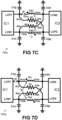
- FIG. 7C shows a circuit 740c similar to the circuit 740a of FIG. 7A but with an inadvertent or unintended disconnection between an oscillator pin of an integrated device and a transmitter coil, and illustrates that the circuit 740a of FIG. 7A is tolerant to such a single failure.
- the resistors R1 and R2 may have a resistance in the range from 30 to 120 Ohm, or from 45 to 90 Ohm, or from 50 to 70 Ohm.
- the present invention is not limited to this example, and solutions with other values for the transmitter coils, and for the capacitors, and for the resonance frequency, and for the resistors, can also be used.
- FIG. 7D shows a circuit 740d similar to the circuit 740a of FIG. 7A but with an inadvertent or unintended open solder joint at an oscillator pin (e.g. LCP1), and illustrates that the circuit 740a of FIG. 7A is tolerant to such a single failure.
- an oscillator pin e.g. LCP1
- FIG. 7E shows a circuit 740e similar to the circuit 740a of FIG. 7A but with an inadvertent or unintended open solder joint of one of the capacitors (e.g. C1p), and illustrates that the circuit 740a of FIG. 7A is tolerant to such a single failure.
- an inadvertent or unintended open solder joint of one of the capacitors e.g. C1p
- f LCO 1 2 ⁇ 1 + k L TX 2 2 C TX 3 ⁇ 1 2 ⁇ 2 3 L TX C TX
- the integrated devices IC1, IC2 may be configured to detect this frequency difference, and/or this different in the current contribution, and to report such a detection, e.g. to an external controller (not shown) communicatively connected to the integrated devices IC1, IC2.
- an external controller not shown
- a single open solder joint on any of the capacitor C1p, C1n, C2p, C2n will lead to the same effect.
- FIG. 7F shows a circuit 740f similar to the circuit 740a of FIG. 7A but with an inadvertent or unintended short circuit across one of the capacitors, and illustrates that the circuit 740a of FIG. 7A is tolerant to such a single failure.
- the terminals of C1p are shorted, thereby effectively connecting LCP1 to ground. Since the LC configuration changes due to this short, the oscillation frequency will also change.
- f LCO 1 2 ⁇ 1 + k L TX 2 2 C TX ⁇ 1 2 ⁇ 2 L TX C TX
- the integrated device may be configured to detect this frequency difference, and/or this increase in current contribution, and to report such a detection, e.g. to an external controller (not shown) communicatively connected thereto.
- an external controller not shown
- FIG. 7G shows a circuit 740g similar to the circuit 740a of FIG. 7A but with an inadvertent or unintended short circuit across one of the resistors, and illustrates that the circuit 740a of FIG. 7A is tolerant to such a single failure.
- the terminals R1a and R1b of R1 are shorted.
- the integrated devices IC1, IC2 are configured to detect the presence of the correct resistor values of R1 and R2, e.g. during a startup-check. Such a test may comprise for example: applying a predefined voltage over said oscillator pins and measuring a current; or may comprise for example the measurement of a time constant when charging or discharging a capacitor through said resistor. As the configuration is fully symmetrical, a single short circuit across any of the resistors R1, R2 will lead to the same effect.
- FIG. 7H shows a circuit 740h similar to the circuit 740a of FIG. 7A but with an inadvertent or unintended disconnection or an open solder joint between an oscillator pin (e.g. LCN2) and one of the resistors (e.g. R2), and illustrates that the circuit 740a of FIG. 7A is tolerant to such a single failure.
- an oscillator pin e.g. LCN2
- R2 resistors
- FIG. 8 is a schematic representation of a third embodiment of an electric circuit 840 proposed by the present invention, that can be used in the inductive angle sensor arrangement 400a of FIG. 4A or 400b of FIG. 4B , or variants thereof.
- the circuit 840 of FIG. 8 can be seen as a variant of the circuit 640 of FIG. 6A with the addition of a low-resistance connection between the centre-taps of the two transmitter coils TX1, TX2, e.g. by means of a resistor R3, preferably having a resistance value smaller than 20 Ohm, or smaller than 10 Ohm, or smaller than 5 Ohm, or even smaller than 1 Ohm, or by means of a PCB layout track.
- the circuit 840 of FIG. 8 offers the advantage over the circuit 740 of FIG. 7A that no discrete resistors R1, R2 need to be mounted on the PCB (i.e. easier to produce, and having a lower component count), but it may lead to larger frequency deviations in some of the failure modes described above.
- this circuit 840 is tolerant to the faults described above, e.g. as illustrated in FIG. 7B to FIG. 7F .
- FIG. 9 is a schematic representation of a fourth embodiment of an electric circuit 940 proposed by the present invention, that can be used in the inductive angle sensor arrangement 400a of FIG. 4A or 400b of FIG. 4B , or variants thereof. While not explicitly shown, each IC may be connected to a set of 2 or 3 receiver coils.
- the circuit 940 can be considered as a variant of the circuit 740 of FIG. 7A , but having four integrated devices IC1, IC2, IC3, IC4 instead of only two, and having four transmitter coils TX1, TX2, TX3, TX4, and having a first set of four cross-coupled resistors Rxp (where "x" is an integer value from 1 to 4) between the LCP pins of two integrated devices, and having a second set of four cross-coupled resistors Rxn (where "x" is an integer value from 1 to 4) between the LCN pins of two integrated devices.
- FIG. 9 shows a schematic representation of an electric circuit 940 that can be used in the inductive angle sensor arrangement 400a of FIG. 4A or 400b of FIG. 4B , or variants thereof, the circuit 940 comprising:
- the term “subsequent integrated device” can mean e.g. "the next IC in clockwise direction”, thus in FIG. 9 : IC2 is subsequent of IC1, IC3 is subsequent of IC2, IC4 is subsequent of IC3, IC1 is subsequent of IC4.
- the term “previous integrated device” can mean e.g. "the next IC in counterclockwise direction”, thus in FIG. 9 : IC1 is previous of IC2, IC2 is previous of IC3, IC3 is previous of IC4, IC4 is previous of IC1.
- the inductive angle sensor may further comprise one or both of:
- the circuit has only three integrated devices and an equal number of transmitter coils.
- the circuit has more than four integrated devices and an equal number of transmitter coils.
- the first set of cross-coupled resistors are omitted, or the second set of cross-coupled resistors are omitted, or both sets of cross-coupled resistors are omitted (e.g. as in FIG. 6A ).
- the first set and the second set of cross-coupled resistors are omitted, but resistors and/or PCB tracks are added to interconnect centre tabs of the transmitter coils with each other.
Landscapes
- Physics & Mathematics (AREA)
- General Physics & Mathematics (AREA)
- Electromagnetism (AREA)
- Transmission And Conversion Of Sensor Element Output (AREA)
- Semiconductor Integrated Circuits (AREA)
Claims (15)
- Induktiver Winkelsensor, umfassend:- eine erste Sendespule (TX1);- eine zweite Sendespule (TX2), die induktiv mit der ersten Sendespule (TX1) gekoppelt ist, wobei die erste und die zweite Sendespule zusammen ein induktiv gekoppeltes Sendespulensystem bilden;- einen ersten Satz von Empfängerspulen (RX1a, RX1b, RX1c), der mindestens zwei oder mindestens drei Empfängerspulen umfasst;- einen zweiten Satz von Empfängerspulen (Rx2a, RX2b, RX2c), der mindestens zwei oder mindestens drei Empfängerspulen umfasst;- ein erstes integriertes Bauelement (IC1) mit einem ersten Oszillatorstift (LCP1) und einem zweiten Oszillatorstift (LCN1), und mit einer Erregerschaltung zum Bereitstellen eines Wechselsignals über seine Oszillatorstifte (LCP1, LCN1); und mit einer Vielzahl von Empfängerstiften, die mit dem ersten Satz von Empfängerspulen (RX1a, RX1b, RX1c) verbunden sind, und einer Auswerteschaltung zum Auswerten von Signalen, die von dem ersten Satz von Empfängerspulen erhalten werden;- ein zweites integriertes Bauelement (IC2) mit einem ersten Oszillatorstift (LCP2) und einem zweiten Oszillatorstift (LCN2), und mit einer Erregerschaltung zum Bereitstellen eines Wechselsignals über seine Oszillatorstifte (LCP2, LCN2); und mit einer Vielzahl von Empfängerstiften, die mit dem zweiten Satz von Empfängerspulen (RX2a, RX2b, RX2c) verbunden sind, und einer Auswerteschaltung zum Auswerten von Signalen, die von dem zweiten Satz von Empfängerspulen erhalten werden;- mindestens ein bewegliches Ziel (112; 312; 412a, 412a', 412b, 412b') zum Bereitstellen einer induktiven Kopplung zwischen dem induktiv gekoppelten Senderspulensystem und jedem Satz von Empfängerspulen;dadurch gekennzeichnet, dassdie erste Sendespule (TX1) ein erstes Ende (TX1a) aufweist, das betriebsmäßig mit dem ersten Oszillatorstift (LCP1) des ersten integrierten Bauelement (IC1) verbunden ist, und ein zweites Ende (TX1b) aufweist, das betriebsmäßig mit dem zweiten Oszillatorstift (LCN2) der zweiten integrierten Bauelements (IC2) verbunden ist; unddie zweite Sendespule (TX2) ein erstes Ende (TX2a) aufweist, das betriebsmäßig mit dem ersten Oszillatorstift (LCP2) des zweiten integrierten Bauelements (IC2) verbunden ist, und ein zweites Ende (TX2b) aufweist, das betriebsmäßig mit dem zweiten Oszillatorstift (LCN1) des ersten integrierten Bauelements (IC1) verbunden ist.
- Induktiver Winkelsensor nach Anspruch 1,wobei das erste integrierte Bauelement (IC1) ein erstes gehäustes Halbleiterbauelement mit einer Vielzahl von Stiften ist, und wobei der erste Oszillatorstift (LCP1) und der zweite Oszillatorstift (LCN1) des ersten integrierten Bauelements benachbarte Stifte des ersten gehäusten Halbleiterbauelements sind;und/oder wobei das zweite integrierte Bauelement (IC2) ein zweites gehäustes Halbleiterbauelement mit einer Vielzahl von Stiften ist, und wobei der erste Oszillatorstift (LCP2) und der zweite Oszillatorstift (LCN2) des zweiten integrierten Bauelements benachbarte Stifte des zweiten gehäusten Halbleiterbauelements sind.
- Induktiver Winkelsensor nach einem der vorhergehenden Ansprüche,ferner umfassend einen ersten Kondensator (C1p), dessen erstes Ende mit dem ersten Oszillatorstift (LCP1) des ersten integrierten Bauelements (IC1) verbunden ist und dessen zweites Ende mit einer ersten Referenzspannung verbunden ist;und ferner umfassend einen zweiten Kondensator (C1n), dessen erstes Ende mit dem zweiten Oszillatorstift (LCN1) des ersten integrierten Bauelements (IC1) verbunden ist und dessen zweites Ende mit einer zweiten Referenzspannung verbunden ist;und ferner umfassend einen dritten Kondensator (C2p), dessen erstes Ende mit dem ersten Oszillatorstift (LCP2) des zweiten integrierten Bauelements (IC2) verbunden ist und dessen zweites Ende mit einer dritten Referenzspannung verbunden ist;und ferner umfassend einen vierten Kondensator (C2n), dessen erstes Ende mit dem zweiten Oszillatorstift (LCN2) des zweiten integrierten Bauelements (IC2) verbunden ist und dessen zweites Ende mit einer vierten Referenzspannung verbunden ist.
- Induktiver Winkelsensor nach einem der vorhergehenden Ansprüche,wobei die erste Auswerteschaltung zum Bestimmen eines ersten Winkelwerts (α1) basierend auf den von dem ersten Satz von Empfängerspulen (RX1a, RX1b, RX1c) erhaltenen Signalen konfiguriert ist;und wobei die zweite Auswerteschaltung zum Bestimmen eines zweiten Winkelwerts (α2) basierend auf den von dem zweiten Satz von Empfängerspulen (Rx2a, RX2b, RX2c) erhaltenen Signalen konfiguriert ist.
- Induktiver Winkelsensor nach einem der vorhergehenden Ansprüche,
wobei eine zentrale Position der ersten Sendespule (TX1) mit einer zentralen Position der zweiten Sendespule (TX2) über einen Kurzschluß oder über einen Widerstand elektrisch verbunden ist. - Induktiver Winkelsensor nach einem der vorhergehenden Ansprüche,
der ferner eines oder beide der folgenden Elemente umfasst:- einen ersten Widerstand (R1), dessen erstes Ende (R1a) mit dem ersten Oszillatorstift (LCP1) des ersten integrierten Bauelements (IC1) verbunden ist und dessen zweites Ende (R1b) mit dem ersten Oszillatorstift (LCP2) des zweiten integrierten Bauelements (IC2) verbunden ist;- einen zweiten Widerstand (R2), dessen erstes Ende (R2a) mit dem zweiten Oszillatorstift (LCN1) des ersten integrierten Bauelements (IC1) verbunden ist und dessen zweites Ende (R2b) mit dem zweiten Oszillatorstift (LCN2) des zweiten integrierten Bauelements (IC2) verbunden ist. - Induktiver Winkelsensor nach einem der vorhergehenden Ansprüche,
wobei sowohl das erste als auch das zweite integrierte Bauelement (IC1, IC2) ferner so konfiguriert is, dass es einen Schwingungsverlust über seinen ersten und zweiten Oszillatorstift erkennt. - Induktiver Winkelsensor nach einem der vorhergehenden Ansprüche,
wobei das erste und zweite integrierte Bauelement (IC1, IC2) ferner dazu konfiguriert sind, einen Frequenzwert einer Schwingung über ihren ersten und zweiten Oszillatorstift zu bestimmen, und ferner dazu konfiguriert sind, einen Fehler basierend auf diesem Frequenzwert zu erkennen. - Induktiver Winkelsensor nach einem der vorhergehenden Ansprüche,umfassend ein einzelnes bewegliches Ziel (112; 312; 412a', 412b');wobei sowohl das erste als auch das zweite integrierte Bauelement (IC1, IC2) zum Bestimmen einer Winkelposition (α1, α2) des einzelnen beweglichen Ziels konfiguriert ist.
- Induktiver Winkelsensor nach Anspruch 9,wobei das erste integrierte Bauelement (IC1) zum Bestimmen eines ersten Winkelwerts (α1) des einzelnen beweglichen Ziels konfiguriert ist;und wobei das zweite integrierte Bauelement (IC2) zum Bestimmen eines zweiten Winkelwerts (α2) des einzelnen beweglichen Ziels konfiguriert ist;und wobei der induktive Winkelsensor ferner zum Bestimmen einer Konsistenz zwischen dem ersten Winkelwert (α1) und dem zweiten Winkelwert (α2) konfiguriert ist.
- Induktiver Winkelsensor nach einem der Ansprüche 1 bis 8,der ein erstes bewegliches Ziel (412a') mit einer ersten Periodizität umfasst, und ein zweites bewegliches Ziel (412b') mit einer zweiten Periodizität, die sich von der ersten Periodizität unterscheidet;und wobei der erste Satz von Empfängerspulen eine Periodizität aufweist, die gleich der ersten Periodizität ist, und wobei der zweite Satz von Empfängerspulen eine Periodizität aufweist, die gleich der zweiten Periodizität ist;und wobei das erste integrierte Bauelement (IC1) zum Bestimmen einer ersten Winkelposition (α1) des ersten beweglichen Ziels relativ zu dem ersten Satz von Empfängerspulen konfiguriert ist;und wobei das zweite integrierte Bauelement (IC2) zum Bestimmen einer zweiten Winkelposition (α2) des zweiten beweglichen Ziels relativ zu dem zweiten Satz von Empfängerspulen konfiguriert ist;und wobei der induktive Winkelsensor ferner zum Bestimmen einer absoluten Winkelposition basierend auf dem ersten Winkelwert (α1) und dem zweiten Winkelwert (α2) konfiguriert ist.
- Drehmomentsensor (400a), umfassend:einen Torsionsstab (441);einen induktiven Winkelsensor nach einem der Ansprüche 1 bis 8, der ein erstes bewegliches Ziel (412a) und ein zweites bewegliches Ziel (412b) umfasst;wobei das erste bewegliche Ziel (412a) mit dem Torsionsstab (441) in einer ersten axialen Position verbunden ist, und das zweite bewegliche Ziel (412b) mit dem Torsionsstab (441) in einer zweiten axialen Position verbunden ist, die von der ersten axialen Position beabstandet ist.
- Drehmomentsensor nach Anspruch 12,wobei das erste integrierte Bauelement (IC1) zum Bestimmen einer ersten Winkelposition (α1) des ersten beweglichen Ziels relativ zum ersten Satz von Empfängerspulen (RX1a, RX1b, RX1c) konfiguriert ist;und wobei das zweite integrierte Bauelement (IC2) zum Bestimmen einer zweiten Winkelposition (α2) des zweiten beweglichen Ziels relativ zum zweiten Satz von Empfängerspulen (RX2a, RX2b, RX2c) konfiguriert ist;und wobei der Drehmomentsensor ferner dazu konfiguriert ist, eine Differenz zwischen dem ersten Winkelwert (α1) und dem zweiten Winkelwert (α2) zu bestimmen und diese Differenz oder einen davon abgeleiteten Wert als einen Wert bereitzustellen, der das zu messende Drehmoment angibt.
- Induktiver Winkelsensor, umfassend:- eine Anzahl N von induktiv gekoppelten Sendespulen (TX1, TX2, TX3, TX4), die zusammen ein induktiv gekoppeltes Sendespulensystem bilden, wobei N mindestens drei ist;- eine Vielzahl von Empfängerspulensätzen, wobei jeder Empfängerspulensatz mindestens zwei oder mindestens drei Empfängerspulen umfasst;- eine Anzahl N von integrierten Bauelementen (IC1, IC2, IC3, IC4), wobei jedes integrierte Bauelement einen ersten und einen zweiten Oszillatorstift (LCP1,LCN1; LCP2,LCN2; LCP3,LCN3; LCP4,LCN4) aufweist, und jedes integrierte Bauelement eine Erregungsschaltung zum Bereitstellen eines Wechselsignals über seine Oszillatorstifte aufweist, und jedes integrierte Bauelement eine Auswertungsschaltung aufweist zum Auswerten von Signalen, die von einem der Sätze von Empfängerspulen erhalten werden;- mindestens ein bewegliches Ziel (112; 312; 412a, 412b) zum Bereitstellen einer induktiven Kopplung zwischen dem induktiv gekoppelten Senderspulensystem und den Empfängerspulensätzen;
dadurch gekennzeichnet, dass- jede Sendespule (TX1, TX2, TX3, TX4) ein erstes Ende (TX1a, TX2a, TX3a, TX4a) aufweist, das betriebsmäßig mit einem ersten Oszillatorstift (LCP1, LCP2, LCP3, LCP4) eines ersten integrierten Bauelements (IC1, IC2, IC3, IC4) verbunden ist, und ein zweites Ende (TX1b, TX2b, TX3b, TX4b) aufweist, das betriebsmäßig mit einem zweiten Oszillatorstift (LCN2, LCN3, LCN4, LCN1) eines nachfolgenden integrierten Bauelements (IC2, IC3, IC4, IC1) verbunden ist. - Induktiver Winkelsensor nach Anspruch 14,
der ferner eines oder beide der folgenden Elemente umfasst:i) eine Anzahl N von ersten elektrischen Widerständen (R1p, R2p, R3p, R4p), deren erstes Ende mit einem ersten Oszillatorstift (LCP1, LCP2, LCP3, LCP4) eines ersten integrierten Bauelements (IC1, IC2, IC3, IC4) verbunden ist und deren zweites Ende mit dem ersten Oszillatorstift (LCP2, LCP3, LCP4, LCP1) eines nachfolgenden integrierten Bauelements (IC2, IC3, IC4, IC1) verbunden ist;ii) eine Anzahl N von zweiter elektrischen Widerständen (R1n, R2n, R3n, R4n), deren erstes Ende mit einem zweiten Oszillatorstift (LCN1, LCN2, LCN3, LCN4) eines ersten integrierten Bauelements (IC1, IC2, IC3, IC4) verbunden ist und deren zweites Ende mit dem zweiten Oszillatorstift (LCN4, LCN1, LCN2, LCN3) eines vorherigen integrierten Bauelements (IC4, IC1, IC2, IC3) verbunden ist.
Priority Applications (3)
| Application Number | Priority Date | Filing Date | Title |
|---|---|---|---|
| EP23190710.6A EP4394331B1 (de) | 2023-08-09 | 2023-08-09 | Induktiver winkelsensor und induktiver drehmomentsensor |
| US18/780,642 US12140486B1 (en) | 2023-08-09 | 2024-07-23 | Inductive angle sensor and inductive torque sensor |
| CN202411085245.9A CN119468900A (zh) | 2023-08-09 | 2024-08-08 | 感应式角度传感器和感应式扭矩传感器 |
Applications Claiming Priority (1)
| Application Number | Priority Date | Filing Date | Title |
|---|---|---|---|
| EP23190710.6A EP4394331B1 (de) | 2023-08-09 | 2023-08-09 | Induktiver winkelsensor und induktiver drehmomentsensor |
Publications (2)
| Publication Number | Publication Date |
|---|---|
| EP4394331A1 EP4394331A1 (de) | 2024-07-03 |
| EP4394331B1 true EP4394331B1 (de) | 2025-04-16 |
Family
ID=87567258
Family Applications (1)
| Application Number | Title | Priority Date | Filing Date |
|---|---|---|---|
| EP23190710.6A Active EP4394331B1 (de) | 2023-08-09 | 2023-08-09 | Induktiver winkelsensor und induktiver drehmomentsensor |
Country Status (3)
| Country | Link |
|---|---|
| US (1) | US12140486B1 (de) |
| EP (1) | EP4394331B1 (de) |
| CN (1) | CN119468900A (de) |
Families Citing this family (8)
| Publication number | Priority date | Publication date | Assignee | Title |
|---|---|---|---|---|
| DE102020216144A1 (de) * | 2020-12-17 | 2022-06-23 | Robert Bosch Gesellschaft mit beschränkter Haftung | Induktiver Positionssensor, Einrichtung |
| US11940470B2 (en) | 2022-05-31 | 2024-03-26 | Allegro Microsystems, Llc | Current sensor system |
| US12352607B2 (en) | 2022-06-28 | 2025-07-08 | Allegro Microsystems, Llc | Position sensing method |
| DE102022208799A1 (de) * | 2022-08-25 | 2024-03-07 | Robert Bosch Gesellschaft mit beschränkter Haftung | Induktive Sensoranordnung zur Erfassung einer Drehbewegung |
| US12578176B2 (en) | 2023-03-22 | 2026-03-17 | Allegro Microsystems, Llc | Angle sensor using eddy currents and having harmonic compensation |
| US20250029780A1 (en) * | 2023-07-19 | 2025-01-23 | Allegro Microsystems, Llc | Position sensing method and system |
| US12455178B2 (en) | 2023-12-22 | 2025-10-28 | Allegro Microsystems, Llc | Inductive linear stroke sensor using dual tracks with different periodicity |
| WO2026048602A1 (ja) * | 2024-08-28 | 2026-03-05 | パナソニックIpマネジメント株式会社 | 回転センサ |
Family Cites Families (13)
| Publication number | Priority date | Publication date | Assignee | Title |
|---|---|---|---|---|
| ATE23756T1 (de) * | 1981-02-09 | 1986-12-15 | Goring Kerr Ltd | Metallsuchgeraet. |
| DE102008006865B4 (de) | 2008-01-31 | 2024-02-29 | HELLA GmbH & Co. KGaA | Induktiver Drehmomentsensor |
| US10837848B2 (en) * | 2016-12-12 | 2020-11-17 | Integrated Device Technology, Inc. | Ultra-thin combined inductive torque and angle sensor for steering wheel position sensing |
| DE102017210655B4 (de) * | 2017-06-23 | 2023-12-21 | Robert Bosch Gmbh | Drehwinkelsensor |
| EP3792599B1 (de) * | 2019-09-12 | 2023-05-03 | TE Connectivity Belgium BVBA | Sensorvorrichtung zur messung der drehposition eines elements |
| EP3885711B1 (de) * | 2020-03-25 | 2023-03-01 | Melexis Technologies SA | Induktiver positionssensor |
| US11692887B2 (en) * | 2020-06-11 | 2023-07-04 | Kyocera Avx Components (Werne) Gmbh | Torque sensing device and method |
| EP3961926B1 (de) * | 2020-08-31 | 2025-07-23 | Melexis Bulgaria Ltd. | Näherungssensorvorrichtung und -system |
| EP3988903A1 (de) * | 2020-10-22 | 2022-04-27 | Renesas Electronics America Inc. | Position sensor system |
| WO2022132229A1 (en) * | 2020-12-14 | 2022-06-23 | Microchip Technology Inc. | High resolution angular inductive sensor and associated method of use |
| EP4047323B1 (de) * | 2021-02-17 | 2023-07-26 | Melexis Technologies SA | Verfahren und system für induktiven winkelsensor |
| US11994387B2 (en) * | 2021-04-13 | 2024-05-28 | Infineon Technologies Ag | Inductive sensor with improved safety |
| EP4198458B1 (de) * | 2021-12-20 | 2024-04-24 | Melexis Technologies SA | Vorrichtung und verfahren zur bestimmung einer winkelposition eines induktiven positionssensors |
-
2023
- 2023-08-09 EP EP23190710.6A patent/EP4394331B1/de active Active
-
2024
- 2024-07-23 US US18/780,642 patent/US12140486B1/en active Active
- 2024-08-08 CN CN202411085245.9A patent/CN119468900A/zh active Pending
Also Published As
| Publication number | Publication date |
|---|---|
| US12140486B1 (en) | 2024-11-12 |
| CN119468900A (zh) | 2025-02-18 |
| EP4394331A1 (de) | 2024-07-03 |
Similar Documents
| Publication | Publication Date | Title |
|---|---|---|
| EP4394331B1 (de) | Induktiver winkelsensor und induktiver drehmomentsensor | |
| US10921155B2 (en) | Multi cycle dual redundant angular position sensing mechanism and associated method of use for precise angular displacement measurement | |
| US11656101B2 (en) | Redundant angular position sensor and associated method of use | |
| US9945653B2 (en) | Inductive position sensor | |
| CN105659053B (zh) | 用于确定转子位移的非接触式传感器 | |
| EP2579001B1 (de) | Detektor | |
| CN102150016B (zh) | 电感式位置传感器、装备其的测量系统和驱动位置传感器的方法 | |
| CN114608620A (zh) | 扫描元件以及具有该扫描元件的感应式位置测量装置 | |
| WO2006067420A1 (en) | Inductive position sensor | |
| CN114441989A (zh) | 检测差动操作线网中线路短路和/或中断的电路和方法 | |
| CN118043680A (zh) | 电流传感器 | |
| US11268832B2 (en) | Coil assembly and corresponding measuring assembly | |
| CN110701986B (zh) | 电磁感应式位置传感器的传感器基板及其制造方法 | |
| JP2021043035A (ja) | 磁歪式センサ用温度検出回路、磁歪式センサ、及び磁歪式センサの温度検出方法 | |
| US20250369741A1 (en) | Inductive position detector | |
| US20250244149A1 (en) | Measured Value Acquisition Device for an Inductive Sensor Arrangement | |
| JP2006267045A (ja) | トルクセンサ | |
| JP2019021988A (ja) | 通信装置およびそれを備えた自動車 | |
| CN111247395B (zh) | 电容式传感器系统 | |
| US12526012B1 (en) | Wireless power transmission with channel redundancy | |
| CN113267119A (zh) | 角度和/或扭矩传感器系统及应用到其中的方法 | |
| JP2004221574A (ja) | バイパスコンデンサの実装・非実装検査方法および多層基板のスルーホール断線検出方法 | |
| JP2007286004A (ja) | 基板検査装置及び基板検査方法 | |
| JP5648435B2 (ja) | 電動パワーステアリング装置およびこれを備える車両 | |
| CN117622320A (zh) | 一种转向系统的高安全性扭矩角度位置检测系统和方法 |
Legal Events
| Date | Code | Title | Description |
|---|---|---|---|
| PUAI | Public reference made under article 153(3) epc to a published international application that has entered the european phase |
Free format text: ORIGINAL CODE: 0009012 |
|
| STAA | Information on the status of an ep patent application or granted ep patent |
Free format text: STATUS: THE APPLICATION HAS BEEN PUBLISHED |
|
| AK | Designated contracting states |
Kind code of ref document: A1 Designated state(s): AL AT BE BG CH CY CZ DE DK EE ES FI FR GB GR HR HU IE IS IT LI LT LU LV MC ME MK MT NL NO PL PT RO RS SE SI SK SM TR |
|
| STAA | Information on the status of an ep patent application or granted ep patent |
Free format text: STATUS: REQUEST FOR EXAMINATION WAS MADE |
|
| 17P | Request for examination filed |
Effective date: 20240721 |
|
| RBV | Designated contracting states (corrected) |
Designated state(s): AL AT BE BG CH CY CZ DE DK EE ES FI FR GB GR HR HU IE IS IT LI LT LU LV MC ME MK MT NL NO PL PT RO RS SE SI SK SM TR |
|
| GRAP | Despatch of communication of intention to grant a patent |
Free format text: ORIGINAL CODE: EPIDOSNIGR1 |
|
| STAA | Information on the status of an ep patent application or granted ep patent |
Free format text: STATUS: GRANT OF PATENT IS INTENDED |
|
| GRAS | Grant fee paid |
Free format text: ORIGINAL CODE: EPIDOSNIGR3 |
|
| GRAA | (expected) grant |
Free format text: ORIGINAL CODE: 0009210 |
|
| STAA | Information on the status of an ep patent application or granted ep patent |
Free format text: STATUS: THE PATENT HAS BEEN GRANTED |
|
| INTG | Intention to grant announced |
Effective date: 20250220 |
|
| AK | Designated contracting states |
Kind code of ref document: B1 Designated state(s): AL AT BE BG CH CY CZ DE DK EE ES FI FR GB GR HR HU IE IS IT LI LT LU LV MC ME MK MT NL NO PL PT RO RS SE SI SK SM TR |
|
| REG | Reference to a national code |
Ref country code: GB Ref legal event code: FG4D |
|
| RIN1 | Information on inventor provided before grant (corrected) |
Inventor name: AKERMI, YASSINE Inventor name: KUMAR, SOUMIL Inventor name: EL-SHENNAWY, MOHAMMED |
|
| REG | Reference to a national code |
Ref country code: CH Ref legal event code: EP |
|
| REG | Reference to a national code |
Ref country code: IE Ref legal event code: FG4D |
|
| REG | Reference to a national code |
Ref country code: DE Ref legal event code: R096 Ref document number: 602023002932 Country of ref document: DE |
|
| REG | Reference to a national code |
Ref country code: NL Ref legal event code: MP Effective date: 20250416 |
|
| PG25 | Lapsed in a contracting state [announced via postgrant information from national office to epo] |
Ref country code: NL Free format text: LAPSE BECAUSE OF FAILURE TO SUBMIT A TRANSLATION OF THE DESCRIPTION OR TO PAY THE FEE WITHIN THE PRESCRIBED TIME-LIMIT Effective date: 20250416 |
|
| REG | Reference to a national code |
Ref country code: AT Ref legal event code: MK05 Ref document number: 1785961 Country of ref document: AT Kind code of ref document: T Effective date: 20250416 |
|
| PG25 | Lapsed in a contracting state [announced via postgrant information from national office to epo] |
Ref country code: FI Free format text: LAPSE BECAUSE OF FAILURE TO SUBMIT A TRANSLATION OF THE DESCRIPTION OR TO PAY THE FEE WITHIN THE PRESCRIBED TIME-LIMIT Effective date: 20250416 Ref country code: ES Free format text: LAPSE BECAUSE OF FAILURE TO SUBMIT A TRANSLATION OF THE DESCRIPTION OR TO PAY THE FEE WITHIN THE PRESCRIBED TIME-LIMIT Effective date: 20250416 Ref country code: PT Free format text: LAPSE BECAUSE OF FAILURE TO SUBMIT A TRANSLATION OF THE DESCRIPTION OR TO PAY THE FEE WITHIN THE PRESCRIBED TIME-LIMIT Effective date: 20250818 |
|
| PGFP | Annual fee paid to national office [announced via postgrant information from national office to epo] |
Ref country code: DE Payment date: 20250724 Year of fee payment: 3 |
|
| REG | Reference to a national code |
Ref country code: LT Ref legal event code: MG9D |
|
| PG25 | Lapsed in a contracting state [announced via postgrant information from national office to epo] |
Ref country code: GR Free format text: LAPSE BECAUSE OF FAILURE TO SUBMIT A TRANSLATION OF THE DESCRIPTION OR TO PAY THE FEE WITHIN THE PRESCRIBED TIME-LIMIT Effective date: 20250717 Ref country code: NO Free format text: LAPSE BECAUSE OF FAILURE TO SUBMIT A TRANSLATION OF THE DESCRIPTION OR TO PAY THE FEE WITHIN THE PRESCRIBED TIME-LIMIT Effective date: 20250716 |
|
| P01 | Opt-out of the competence of the unified patent court (upc) registered |
Free format text: CASE NUMBER: UPC_APP_6156_4394331/2025 Effective date: 20250907 |
|
| PG25 | Lapsed in a contracting state [announced via postgrant information from national office to epo] |
Ref country code: PL Free format text: LAPSE BECAUSE OF FAILURE TO SUBMIT A TRANSLATION OF THE DESCRIPTION OR TO PAY THE FEE WITHIN THE PRESCRIBED TIME-LIMIT Effective date: 20250416 |
|
| PG25 | Lapsed in a contracting state [announced via postgrant information from national office to epo] |
Ref country code: BG Free format text: LAPSE BECAUSE OF FAILURE TO SUBMIT A TRANSLATION OF THE DESCRIPTION OR TO PAY THE FEE WITHIN THE PRESCRIBED TIME-LIMIT Effective date: 20250416 |
|
| PG25 | Lapsed in a contracting state [announced via postgrant information from national office to epo] |
Ref country code: HR Free format text: LAPSE BECAUSE OF FAILURE TO SUBMIT A TRANSLATION OF THE DESCRIPTION OR TO PAY THE FEE WITHIN THE PRESCRIBED TIME-LIMIT Effective date: 20250416 |
|
| PG25 | Lapsed in a contracting state [announced via postgrant information from national office to epo] |
Ref country code: AT Free format text: LAPSE BECAUSE OF FAILURE TO SUBMIT A TRANSLATION OF THE DESCRIPTION OR TO PAY THE FEE WITHIN THE PRESCRIBED TIME-LIMIT Effective date: 20250416 |
|
| PGFP | Annual fee paid to national office [announced via postgrant information from national office to epo] |
Ref country code: FR Payment date: 20250725 Year of fee payment: 3 |
|
| PG25 | Lapsed in a contracting state [announced via postgrant information from national office to epo] |
Ref country code: RS Free format text: LAPSE BECAUSE OF FAILURE TO SUBMIT A TRANSLATION OF THE DESCRIPTION OR TO PAY THE FEE WITHIN THE PRESCRIBED TIME-LIMIT Effective date: 20250716 |
|
| PG25 | Lapsed in a contracting state [announced via postgrant information from national office to epo] |
Ref country code: IS Free format text: LAPSE BECAUSE OF FAILURE TO SUBMIT A TRANSLATION OF THE DESCRIPTION OR TO PAY THE FEE WITHIN THE PRESCRIBED TIME-LIMIT Effective date: 20250816 |
|
| PG25 | Lapsed in a contracting state [announced via postgrant information from national office to epo] |
Ref country code: LV Free format text: LAPSE BECAUSE OF FAILURE TO SUBMIT A TRANSLATION OF THE DESCRIPTION OR TO PAY THE FEE WITHIN THE PRESCRIBED TIME-LIMIT Effective date: 20250416 |
|
| PG25 | Lapsed in a contracting state [announced via postgrant information from national office to epo] |
Ref country code: SM Free format text: LAPSE BECAUSE OF FAILURE TO SUBMIT A TRANSLATION OF THE DESCRIPTION OR TO PAY THE FEE WITHIN THE PRESCRIBED TIME-LIMIT Effective date: 20250416 Ref country code: DK Free format text: LAPSE BECAUSE OF FAILURE TO SUBMIT A TRANSLATION OF THE DESCRIPTION OR TO PAY THE FEE WITHIN THE PRESCRIBED TIME-LIMIT Effective date: 20250416 |
|
| REG | Reference to a national code |
Ref country code: DE Ref legal event code: R097 Ref document number: 602023002932 Country of ref document: DE |
|
| PG25 | Lapsed in a contracting state [announced via postgrant information from national office to epo] |
Ref country code: CZ Free format text: LAPSE BECAUSE OF FAILURE TO SUBMIT A TRANSLATION OF THE DESCRIPTION OR TO PAY THE FEE WITHIN THE PRESCRIBED TIME-LIMIT Effective date: 20250416 |
|
| PG25 | Lapsed in a contracting state [announced via postgrant information from national office to epo] |
Ref country code: EE Free format text: LAPSE BECAUSE OF FAILURE TO SUBMIT A TRANSLATION OF THE DESCRIPTION OR TO PAY THE FEE WITHIN THE PRESCRIBED TIME-LIMIT Effective date: 20250416 |
|
| PG25 | Lapsed in a contracting state [announced via postgrant information from national office to epo] |
Ref country code: SK Free format text: LAPSE BECAUSE OF FAILURE TO SUBMIT A TRANSLATION OF THE DESCRIPTION OR TO PAY THE FEE WITHIN THE PRESCRIBED TIME-LIMIT Effective date: 20250416 |
|
| PG25 | Lapsed in a contracting state [announced via postgrant information from national office to epo] |
Ref country code: IT Free format text: LAPSE BECAUSE OF FAILURE TO SUBMIT A TRANSLATION OF THE DESCRIPTION OR TO PAY THE FEE WITHIN THE PRESCRIBED TIME-LIMIT Effective date: 20250416 |
|
| PLBE | No opposition filed within time limit |
Free format text: ORIGINAL CODE: 0009261 |
|
| STAA | Information on the status of an ep patent application or granted ep patent |
Free format text: STATUS: NO OPPOSITION FILED WITHIN TIME LIMIT |
|
| REG | Reference to a national code |
Ref country code: CH Ref legal event code: L10 Free format text: ST27 STATUS EVENT CODE: U-0-0-L10-L00 (AS PROVIDED BY THE NATIONAL OFFICE) Effective date: 20260225 |
|
| PG25 | Lapsed in a contracting state [announced via postgrant information from national office to epo] |
Ref country code: RO Free format text: LAPSE BECAUSE OF FAILURE TO SUBMIT A TRANSLATION OF THE DESCRIPTION OR TO PAY THE FEE WITHIN THE PRESCRIBED TIME-LIMIT Effective date: 20250416 |
|
| 26N | No opposition filed |
Effective date: 20260119 |
|
| PG25 | Lapsed in a contracting state [announced via postgrant information from national office to epo] |
Ref country code: MC Free format text: LAPSE BECAUSE OF FAILURE TO SUBMIT A TRANSLATION OF THE DESCRIPTION OR TO PAY THE FEE WITHIN THE PRESCRIBED TIME-LIMIT Effective date: 20250416 |
|
| PG25 | Lapsed in a contracting state [announced via postgrant information from national office to epo] |
Ref country code: LU Free format text: LAPSE BECAUSE OF NON-PAYMENT OF DUE FEES Effective date: 20250809 |