EP4394255A1 - A cooking device comprising an ignition switch - Google Patents
A cooking device comprising an ignition switch Download PDFInfo
- Publication number
- EP4394255A1 EP4394255A1 EP23213034.4A EP23213034A EP4394255A1 EP 4394255 A1 EP4394255 A1 EP 4394255A1 EP 23213034 A EP23213034 A EP 23213034A EP 4394255 A1 EP4394255 A1 EP 4394255A1
- Authority
- EP
- European Patent Office
- Prior art keywords
- knob
- actuation member
- cooking device
- actuation
- channel
- Prior art date
- Legal status (The legal status is an assumption and is not a legal conclusion. Google has not performed a legal analysis and makes no representation as to the accuracy of the status listed.)
- Withdrawn
Links
Images



Classifications
-
- F—MECHANICAL ENGINEERING; LIGHTING; HEATING; WEAPONS; BLASTING
- F24—HEATING; RANGES; VENTILATING
- F24C—DOMESTIC STOVES OR RANGES ; DETAILS OF DOMESTIC STOVES OR RANGES, OF GENERAL APPLICATION
- F24C3/00—Stoves or ranges for gaseous fuels
- F24C3/10—Arrangement or mounting of ignition devices
- F24C3/103—Arrangement or mounting of ignition devices of electric ignition devices
-
- F—MECHANICAL ENGINEERING; LIGHTING; HEATING; WEAPONS; BLASTING
- F24—HEATING; RANGES; VENTILATING
- F24C—DOMESTIC STOVES OR RANGES ; DETAILS OF DOMESTIC STOVES OR RANGES, OF GENERAL APPLICATION
- F24C3/00—Stoves or ranges for gaseous fuels
- F24C3/12—Arrangement or mounting of control or safety devices
- F24C3/126—Arrangement or mounting of control or safety devices on ranges
Definitions
- the cooking device of the present invention comprises an actuation member which is positioned so as to move in a channel and which contacts the ignition switch with the movement received from the knob so as to enable the ignition switch to be actuated.
- actuation member By means of the actuation member, a mechanical and durable actuation function can be performed.
- switch structure which can be provided at the base of the tap, only a mechanical spring structure is used in order to prevent the problems of water leakage and the switch dislodging.
- the cooking device of the present invention comprises a spring which is connected to the actuation member such that the actuation member can return to the first position after shifting to the second position as the user moves the knob.
- the relevant spring is positioned on the actuation member such that one end thereof bears against the channel.
- the cooking device of the present invention comprises the knob comprising a knob base which is connected to a knob shaft on each tap and which contacts and pushes the actuation member with the pushing movement of the user.
- the knob base contacts the actuation member.
- the knob base may be flat or have protruding or curved parts.
- the cooking device of the present invention comprises the actuation member comprising the actuation protrusion having a sliding surface inclined between 30° and 60° relative to the longitudinal axis of the channel.
- the cooking device (100) of the present invention comprises a body (101); a burner plate (102) having a plurality of burner groups (103) thereon for heating and/or cooking; a plurality of taps (3) which provide the transfer of the gas to be burned in the burner group (103) in the amount determined by the user; a knob (2) which is connected to each tap (3) and which can be moved by the user; and an ignition switch (4) which actuates the ignition of the burner group (103).
- a single ignition switch (4) which is suitable for mechanical actuation.
- the cooking device (100) of the present invention comprises a spring (13) which is connected to the actuation member (12) such that the actuation member (12) can return to the first position after shifting to the second position as the user moves the knob (2).
- said spring (13) is positioned on the actuation member (12) as shown in Figure 8 , and one end thereof bears against the channel (11).
- the actuation member (12) pressed by the knob (2) compresses said spring (13) in the channel (11).
- the energy accumulated by compressing said spring (13) is released when the user releases the knob (2) and enables the actuation member (12) to shift to the first position as shown in Figure 1 .
- the user When the cooking device (100) of the present invention is in use, the user first grips and presses the hand-held gripping part (21) on the knob (2), then rotates the same to transfer as much gas as desired from the tap (3). During this pressing process, the knob (2) pushes the actuation member (12) and the actuation function for all burner groups (103) is performed by the ignition switch (4) and the burning process begins in the burner group (103) to which gas is supplied.
- the actuation end (122) of the actuation member (12) in the second position extending out of the channel (11) contacts the ignition switch (4) or enters a certain area in the ignition switch (4), and actuates the ignition switch (4) to initiate ignition to burn the delivered gas.
- the cooking device (100) of the present invention comprises a plurality of actuation protrusions (121) which are provided on the actuation member (12), corresponding to each knob (2) and which enable the actuation member (12) to be moved in the channel (11) with the movement received from the knob (2).
- the actuation member (12) comprises actuation protrusions (121) as many as the number of knobs (2) in the cooking device (100), and each actuation protrusion (121) is configured in a similar shape and form.
- the ignition switch (4) is positioned in the same longitudinal axis direction, suitable for being actuated by the actuation end (122) of the actuation member (12) extending out of the channel (11). By means of said actuation end (122), the ignition switch (4) detects that the actuation member (12) is in the second position and starts the ignition process.
- Said ignition switch (4) may be a switch suitable for use in cookers in general and may be connected with a plurality of fixing members on an extension plate of the channel (11).
- the cooking device (100) of the present invention comprises a second type of actuation protrusion (1211) which extends on the actuation member (12) corresponding to each knob (2) and which is inclined between 30° and 60° relative to the longitudinal axis of the channel (11).
- actuation protrusion (1211) there is a second type of actuation protrusion (1211) corresponding to each knob (2).
- the actuation member (12) in the first position comprises the second type of actuation protrusions (1211) in the form of approximately 45° protrusions.
- the actuation member (12) moves by means of the inclined second type actuation protrusion (1211) and actuates the ignition switch (4).
- the second type of actuation protrusion (1211) which is obtained by using less material ensures that the system operates mechanically in a smooth manner.
- a gas cooker can be used as the cooking device (100) of the present invention.
Landscapes
- Engineering & Computer Science (AREA)
- Chemical & Material Sciences (AREA)
- Combustion & Propulsion (AREA)
- Mechanical Engineering (AREA)
- General Engineering & Computer Science (AREA)
- Feeding And Controlling Fuel (AREA)
Abstract
Description
- The present invention relates to a cooking device comprising an improved ignition switch.
- In the state of the art, cooking devices have at least one burner group whereon the product to be cooked/heated is placed. When the user places the cooking vessel on any one of the burner groups, he/she controls the relevant burner group with the knobs which are provided on the panel, each corresponding to a burner group.
- In the cooking device, for example in a cooker, it is known to use an ignition switch connected to the knob to ignite each burner group. By means of said ignition system which eliminates the need for an igniter or similar component to ignite the existing gas, the user is only required to press and turn the knob. On the other hand, using an ignition switch for each knob increases the cost. Water, foodstuff residues or detergent residues leaking into the base of the tap while the user is cooking or cleaning may also cause said ignition switches to jam over time and perform constant ignition.
- Gaskets and similar additional components are needed to protect said ignition switches from external factors. Moreover, switches which are not properly installed by the operator during the production process may become dislodged over time and perform constant ignition.
- In the state of the art Turkish Patent No.
TR 2014/05531 - The aim of present invention is the realization of a cooking device comprising an ignition group wherein instead of using multiple ignition switches, only one is used and problems such as water leaks and possible dislodging of the switches are eliminated.
- The cooking device of the present invention comprises a body; a burner plate having a plurality of burner groups thereon for heating and/or cooking; a plurality of taps which provide the transfer of the gas to be burned in the burner group in the amount determined by the user; a knob which is connected to each tap and which can be moved by the user; and an ignition switch which actuates the ignition of the burner group. Since only one ignition switch is used, advantages in terms of both labor and cost are provided.
- The cooking device of the present invention comprises an actuation member which is positioned so as to move in a channel and which contacts the ignition switch with the movement received from the knob so as to enable the ignition switch to be actuated. By means of the actuation member, a mechanical and durable actuation function can be performed. Instead of the switch structure which can be provided at the base of the tap, only a mechanical spring structure is used in order to prevent the problems of water leakage and the switch dislodging.
- The cooking device of the present invention comprises an actuation member which is positioned so as to move in a channel extending along each knob and which does not actuate the ignition switch in the first position and which, in the second position, contacts and actuates the ignition switch with the movement received from the knob. The actuation member comprises an actuation protrusion which aligns with each knob with the pressure of the spring when the cooking device is not yet in use. While the user presses and turns the desired knob, the actuation protrusion shifts from the first position to the second position. At this time, the ignition switch is enabled to be actuated.
- The cooking device of the present invention comprises a spring which is connected to the actuation member such that the actuation member can return to the first position after shifting to the second position as the user moves the knob. Moreover, the relevant spring is positioned on the actuation member such that one end thereof bears against the channel. Thus, when the user stops gripping the knob, the actuation member under the pressure of the spring is released and moves in the opposite direction in the channel, shifting back to the first position.
- The cooking device of the present invention comprises the knob comprising a knob base which is connected to a knob shaft on each tap and which contacts and pushes the actuation member with the pushing movement of the user. When the user presses the knob, the knob base contacts the actuation member. The knob base may be flat or have protruding or curved parts.
- The cooking device of the present invention comprises a plurality of actuation protrusions which are provided on the actuation member, corresponding to each knob and which enable the actuation member to be moved in the channel with the movement received from the knob. The actuation protrusion which is an extension of the actuation member is positioned to be opposite to each knob. When said actuation protrusion is pushed by the knob base, the actuation member presses against the spring in the channel.
- The cooking device of the present invention comprises an ignition switch which is positioned flush with the channel and which is suitable to be actuated by the actuation end of the actuation member extending out of the channel with the movement received from the knob. By using only one ignition switch, ignition can be performed at all burner groups. By means of this development, the ignition switch is positioned away from the knobs, rather than directly in the vicinity of the knob.
- The cooking device of the present invention comprises a series of actuation protrusions which extend from the opening on the channel to each knob and which are shaped in the form of a V so as to have a bent part. By means of said structure of the actuation protrusion, the actuation member can easily slide in the channel when the knob is pressed in a perpendicular direction.
- The cooking device of the present invention comprises the actuation member comprising the actuation protrusion having a sliding surface inclined between 30° and 60° relative to the longitudinal axis of the channel. By means of the actuation protrusion which is inclined in this optimum range, the actuation member is enabled to move smoothly in the channel.
- The cooking device of the present invention comprises a second type of actuation protrusion which extends on the actuation member corresponding to each knob and which is inclined between 30° and 60° relative to the longitudinal axis of the channel. Said second type of actuation protrusion extends from the actuation member in an inclined direction towards the knob.
- The actuation member of the present invention may be manufactured from a metal wire or may have a width so as to extend to the lateral walls in the channel.
- The cooking device realized in order to attain the aim of the present invention is illustrated in the attached figures, where:
-
Figure 1 - is the perspective view of the gas tap group comprising a series of gas taps and the actuation member in the first position which has not yet actuated the ignition switch in an embodiment of the present invention. -
Figure 2 - is a front view of the gas tap group shown inFigure 1 . -
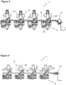
Figure 3 - is the perspective view of a tap know from the gas tap group shown inFigure 1 in the driven status and of the position where the actuation member shifts to the second position to actuate the ignition switch. -
Figure 4 - is a front view of the gas tap group shown inFigure 3 . -
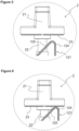
Figure 5 - is the front view of the detail A shown inFigure 2 showing the knob and the actuation protrusion in an enlarged manner. -
Figure 6 - is the front view of the detail B shown inFigure 4 showing the knob driven by the user and the actuation protrusion driven by the knob in an enlarged manner. -
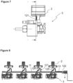
Figure 7 - is the sideways view of the gas tap group related to an embodiment of the present invention. -
Figure 8 - is the cross-sectional view along the line A-A inFigure 7 , showing the gas tap group and the actuation member in the first position. -
Figure 9 - is the sideways view of the gas tap group related to an embodiment of the present invention. -
Figure 10 - is the cross-sectional view along the line A-A inFigure 9 , showing the gas tap group and the actuation member in the second position. -
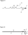
Figure 11 - is the schematic view showing the actuation member, the spring and the ignition switch related to an embodiment of the present invention. -
Figure 12 - is the schematic view wherein the actuation member and the spring shown inFigure 11 are positioned in the channel and connected to the ignition switch. -
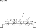
Figure 13 - is the schematic view showing the gas tap group having an actuation member in the first position, having the second type of actuation protrusion, related to an embodiment of the present invention. -
Figure 14 - is a cooking device configured as a cooker suitable to be used in the present invention. -
Figure 15 - is the cross-sectional view of the cooking device taken along the line A-A inFigure 14 . - The elements illustrated in the figures are numbered as follows:
- 1. Gas tap group
- 11. Channel
- 12. Actuation member
- 121. Actuation protrusion
1211. Second type actuation protrusion - 122. Actuation end
- 124. Bent part
- 125. Sliding surface
- 121. Actuation protrusion
- 13. Spring
- 2. Knob
- 21. Gripping part
- 22. Knob shaft
- 23. Knob base
- 3. Tap
- 4. Ignition switch
- 100. Cooking device
- 101. Body
- 102. Burner plate
- 103. Burner group
- The cooking device (100) of the present invention comprises a body (101); a burner plate (102) having a plurality of burner groups (103) thereon for heating and/or cooking; a plurality of taps (3) which provide the transfer of the gas to be burned in the burner group (103) in the amount determined by the user; a knob (2) which is connected to each tap (3) and which can be moved by the user; and an ignition switch (4) which actuates the ignition of the burner group (103). Advantageously, in the cooking device (100), there is only a single ignition switch (4) which is suitable for mechanical actuation. Thus, the need for using an ignition switch (4) for each tap (3) is eliminated and problems such as possible incorrect placement and grouping are prevented during the assembly.
- The cooking device (100) of the present invention comprises an actuation member (12) which is positioned so as to move in a channel (11) and which contacts the ignition switch (4) with the movement received from the knob (2) so as to enable the ignition switch (4) to be actuated.
Figure 1 shows a knob (2) which is not pressed by the user, andFigure 3 shows the actuation member (12) which is activated as said knob (2) is pressed. Accordingly, the actuation member (12) of the present invention is suitable to move in the channel (11) extending along each knob (2) and does not actuate the ignition switch (4) when in the first position, and, when in the second position, contacts and actuates the ignition switch (4) with the movement received from the knob (2). Thus, the need for using an ignition switch (4) in each tap (3) in the state of the art is eliminated and a mechanically actuated system is realized. Consequently, by not using an ignition switch (4) in each tap (3) in the gas tap group (1), the cost is reduced and technical problems such as possible non-ignition or jamming are prevented. - In an embodiment of the present invention, the cooking device (100) of the present invention comprises a spring (13) which is connected to the actuation member (12) such that the actuation member (12) can return to the first position after shifting to the second position as the user moves the knob (2). In another embodiment of the present invention, said spring (13) is positioned on the actuation member (12) as shown in
Figure 8 , and one end thereof bears against the channel (11). Thus, while moving in the channel (11), the actuation member (12) pressed by the knob (2) compresses said spring (13) in the channel (11). The energy accumulated by compressing said spring (13) is released when the user releases the knob (2) and enables the actuation member (12) to shift to the first position as shown inFigure 1 . - When the cooking device (100) of the present invention is in use, the user first grips and presses the hand-held gripping part (21) on the knob (2), then rotates the same to transfer as much gas as desired from the tap (3). During this pressing process, the knob (2) pushes the actuation member (12) and the actuation function for all burner groups (103) is performed by the ignition switch (4) and the burning process begins in the burner group (103) to which gas is supplied.
- In an embodiment of the present invention, the knob (2) is connected to a cylindrically protruding knob shaft (22) which is provided on each tap (3). Said knobs (2) have a knob base (23) which contacts and pushes the actuation member (12) with the pushing movement of the user. As shown in detail in
Figures 5 and 6 , when the knob (2) is pushed towards the cooking device (100) by the user, the knob base (23) of the knob (2) contacts the actuation protrusion (121) of the actuation member (12) and enables the actuation member (12) to shift to the second position. Here, the actuation end (122) of the actuation member (12) in the second position extending out of the channel (11) contacts the ignition switch (4) or enters a certain area in the ignition switch (4), and actuates the ignition switch (4) to initiate ignition to burn the delivered gas. - In an embodiment of the present invention, the cooking device (100) of the present invention comprises a plurality of actuation protrusions (121) which are provided on the actuation member (12), corresponding to each knob (2) and which enable the actuation member (12) to be moved in the channel (11) with the movement received from the knob (2). Referring to
Figure 1 , the actuation member (12) comprises actuation protrusions (121) as many as the number of knobs (2) in the cooking device (100), and each actuation protrusion (121) is configured in a similar shape and form. - In an embodiment of the present invention, the ignition switch (4) is positioned in the same longitudinal axis direction, suitable for being actuated by the actuation end (122) of the actuation member (12) extending out of the channel (11). By means of said actuation end (122), the ignition switch (4) detects that the actuation member (12) is in the second position and starts the ignition process. Said ignition switch (4) may be a switch suitable for use in cookers in general and may be connected with a plurality of fixing members on an extension plate of the channel (11).
- The actuation member (12) of the present invention comprises a series of actuation protrusions (121) which extend from the opening on the channel (11) to each knob (2) and which are shaped in the form of a V so as to have a bent part (124). Said part (124) is composed of an inclined part relative to the actuation member (12) and another part extending perpendicularly relative to said actuation member (12). The bent part (124) forms an angle of approximately 45° within itself. Here, by means of the inclination of the actuation protrusion (121), the actuation member (12) is enabled to make a sliding movement in the channel (11). In an embodiment of the present invention, said actuation member (12) comprises the actuation protrusion (121) having a sliding surface (125) inclined between 30° and 60° relative to the longitudinal axis of the channel (11). As shown in
Figure 4 , said angle can be selected as 45°. - In an embodiment of the present invention, the cooking device (100) of the present invention comprises a second type of actuation protrusion (1211) which extends on the actuation member (12) corresponding to each knob (2) and which is inclined between 30° and 60° relative to the longitudinal axis of the channel (11). Again, just like the actuation protrusion (121), there is a second type of actuation protrusion (1211) corresponding to each knob (2). As shown in
Figure 11 , the actuation member (12) in the first position comprises the second type of actuation protrusions (1211) in the form of approximately 45° protrusions. When the knob (2) is pressed, the actuation member (12) moves by means of the inclined second type actuation protrusion (1211) and actuates the ignition switch (4). The second type of actuation protrusion (1211) which is obtained by using less material ensures that the system operates mechanically in a smooth manner. - In an embodiment of the present invention, the actuation member (12) can be manufactured from metal wire or can be configured to have a larger transversal cross-section. Said actuation member (12) may also be a wire rod manufactured from copper or metal by being wound in the form of a coil.
- As shown in
Figure 14 , a gas cooker can be used as the cooking device (100) of the present invention. There are preferably four burner groups (103) of different sizes and in said burner group (103) there is a burner where the gas is ignited and burned.
Claims (11)
- A cooking device (100) comprising a body (101); a burner plate (102) having a plurality of burner groups (103) thereon for heating and/or cooking; a plurality of taps (3) which provide the transfer of the gas to be burned in the burner group (103) in the amount determined by the user; a knob (2) which is connected to each tap (3) and which can be moved by the user; and an ignition switch (4) which actuates the ignition of the burner group (103), characterized by an actuation member (12) which is positioned so as to move in a channel (11) and which contacts the ignition switch (4) with the movement received from the knob (2) so as to enable the ignition switch (4) to be actuated.
- A cooking device (100) as in Claim 1, characterized by the actuation member (12) which is suitable to move in the channel (11) extending along each knob (2) and which does not actuate the ignition switch (4) when in the first position, and, when in the second position, contacts and actuates the ignition switch (4) with the movement received from the knob (2).
- A cooking device (100) as in Claim 2, characterized by a spring (13) which is connected to the actuation member (12) such that the actuation member (12) can return to the first position after shifting to the second position as the user moves the knob (2).
- A cooking device (100) as in any one of the above claims, characterized by a spring (13) which is positioned on the actuation member (12) and one end of which bears against the channel (11).
- A cooking device (100) as in any one of the above claims, characterized by the knob (2) comprising a knob base (23) which is connected to a knob shaft (22) on each tap (3) and which contacts and pushes the actuation member (12) with the pushing movement of the user.
- A cooking device (100) as in any one of the above claims, characterized by a plurality of actuation protrusions (121) which are provided on the actuation member (12), corresponding to each knob (2) and which enable the actuation member (12) to be moved in the channel (11) with the movement received from the knob (2).
- A cooking device (100) as in any one of the above claims, characterized by an ignition switch (4) which is positioned as aligned with the channel (11) and which is suitable to be actuated by the actuation end (122) of the actuation member (12) extending out of the channel (11) with the movement received from the knob (2).
- A cooking device (100) as in any one of the above claims, characterized by a series of actuation protrusions (121) which extend from the opening on the channel (11) to each knob (2) and which are shaped in the form of a V so as to have a bent part (124).
- A cooking device (100) as in any one of the above claims, characterized by the actuation member (12) comprising the actuation protrusion (121) having a sliding surface (125) inclined between 30° and 60° relative to the longitudinal axis of the channel (11).
- A cooking device (100) as in any one of the above claims, characterized by a second type of actuation protrusion (1211) which extends on the actuation member (12) corresponding to each knob (2) and which is inclined between 30° and 60° relative to the longitudinal axis of the channel (11).
- A cooking device (100) as in any one of the above claims, characterized by an actuation member (12) which is manufactured from a metal wire.
Applications Claiming Priority (1)
| Application Number | Priority Date | Filing Date | Title |
|---|---|---|---|
| TR202220960 | 2022-12-28 |
Publications (1)
| Publication Number | Publication Date |
|---|---|
| EP4394255A1 true EP4394255A1 (en) | 2024-07-03 |
Family
ID=89029882
Family Applications (1)
| Application Number | Title | Priority Date | Filing Date |
|---|---|---|---|
| EP23213034.4A Withdrawn EP4394255A1 (en) | 2022-12-28 | 2023-11-29 | A cooking device comprising an ignition switch |
Country Status (1)
| Country | Link |
|---|---|
| EP (1) | EP4394255A1 (en) |
Citations (2)
| Publication number | Priority date | Publication date | Assignee | Title |
|---|---|---|---|---|
| US20190137100A1 (en) * | 2017-11-08 | 2019-05-09 | Illinois Tool Works Inc. | Device for Controlling the Ignition of Gas Burners of a Domestic Cooking Appliance |
| US20220090792A1 (en) * | 2020-09-23 | 2022-03-24 | Whirlpool Corporation | Appliance ignitor assembly |
-
2023
- 2023-11-29 EP EP23213034.4A patent/EP4394255A1/en not_active Withdrawn
Patent Citations (2)
| Publication number | Priority date | Publication date | Assignee | Title |
|---|---|---|---|---|
| US20190137100A1 (en) * | 2017-11-08 | 2019-05-09 | Illinois Tool Works Inc. | Device for Controlling the Ignition of Gas Burners of a Domestic Cooking Appliance |
| US20220090792A1 (en) * | 2020-09-23 | 2022-03-24 | Whirlpool Corporation | Appliance ignitor assembly |
Similar Documents
| Publication | Publication Date | Title |
|---|---|---|
| TR2022020960A2 (en) | A COOKING DEVICE WITH AN IGNITION KEY | |
| EP3974728A1 (en) | Appliance ignitor assembly | |
| KR200465747Y1 (en) | Apparatus for generating ignition flame of commercialuse gas burnner | |
| KR100575238B1 (en) | Gas range | |
| WO1998048222A2 (en) | Gas range burner system | |
| WO2018202372A1 (en) | A cooktop comprising a knob with a light source | |
| KR101018332B1 (en) | Automatic lighting equipment for gas appliances | |
| JP2020186879A (en) | Heating cooker | |
| KR100675854B1 (en) | Cooker | |
| EP0455896B1 (en) | Automatic unit for igniting appliances containing gas rings | |
| KR200353170Y1 (en) | A roaster for both gas fire and charcoal fire seperated a torch | |
| JP4136718B2 (en) | Cooking device | |
| EP2472183A2 (en) | An ignition switch for gas taps | |
| EP1907756B1 (en) | A cooking device | |
| EP0807789A1 (en) | Device for the control of a plurality of burners of a domestic gas cooking appliance | |
| EP3847397B1 (en) | A gas cooker comprising a knob | |
| JP7577155B2 (en) | Gas stove | |
| JP7206007B2 (en) | calciner | |
| JP6886303B2 (en) | grill | |
| JP7397749B2 (en) | heating cooker | |
| CN115751402B (en) | A temperature control valve | |
| JP7406978B2 (en) | heating cooker | |
| KR0148760B1 (en) | Knob of the stove | |
| JP2003222328A (en) | Gas appliances | |
| GB2319833A (en) | Gas cooking appliance |
Legal Events
| Date | Code | Title | Description |
|---|---|---|---|
| PUAI | Public reference made under article 153(3) epc to a published international application that has entered the european phase |
Free format text: ORIGINAL CODE: 0009012 |
|
| STAA | Information on the status of an ep patent application or granted ep patent |
Free format text: STATUS: REQUEST FOR EXAMINATION WAS MADE |
|
| 17P | Request for examination filed |
Effective date: 20231129 |
|
| AK | Designated contracting states |
Kind code of ref document: A1 Designated state(s): AL AT BE BG CH CY CZ DE DK EE ES FI FR GB GR HR HU IE IS IT LI LT LU LV MC ME MK MT NL NO PL PT RO RS SE SI SK SM TR |
|
| STAA | Information on the status of an ep patent application or granted ep patent |
Free format text: STATUS: EXAMINATION IS IN PROGRESS |
|
| 17Q | First examination report despatched |
Effective date: 20250331 |
|
| STAA | Information on the status of an ep patent application or granted ep patent |
Free format text: STATUS: THE APPLICATION IS DEEMED TO BE WITHDRAWN |
|
| 18D | Application deemed to be withdrawn |
Effective date: 20250801 |