EP2472183A2 - An ignition switch for gas taps - Google Patents
An ignition switch for gas taps Download PDFInfo
- Publication number
- EP2472183A2 EP2472183A2 EP11194306A EP11194306A EP2472183A2 EP 2472183 A2 EP2472183 A2 EP 2472183A2 EP 11194306 A EP11194306 A EP 11194306A EP 11194306 A EP11194306 A EP 11194306A EP 2472183 A2 EP2472183 A2 EP 2472183A2
- Authority
- EP
- European Patent Office
- Prior art keywords
- contact
- gas
- ignition switch
- contact member
- tab
- Prior art date
- Legal status (The legal status is an assumption and is not a legal conclusion. Google has not performed a legal analysis and makes no representation as to the accuracy of the status listed.)
- Ceased
Links
Images


Classifications
-
- F—MECHANICAL ENGINEERING; LIGHTING; HEATING; WEAPONS; BLASTING
- F24—HEATING; RANGES; VENTILATING
- F24C—DOMESTIC STOVES OR RANGES ; DETAILS OF DOMESTIC STOVES OR RANGES, OF GENERAL APPLICATION
- F24C3/00—Stoves or ranges for gaseous fuels
- F24C3/10—Arrangement or mounting of ignition devices
- F24C3/103—Arrangement or mounting of ignition devices of electric ignition devices
-
- H—ELECTRICITY
- H01—ELECTRIC ELEMENTS
- H01H—ELECTRIC SWITCHES; RELAYS; SELECTORS; EMERGENCY PROTECTIVE DEVICES
- H01H19/00—Switches operated by an operating part which is rotatable about a longitudinal axis thereof and which is acted upon directly by a solid body external to the switch, e.g. by a hand
- H01H19/54—Switches operated by an operating part which is rotatable about a longitudinal axis thereof and which is acted upon directly by a solid body external to the switch, e.g. by a hand the operating part having at least five or an unspecified number of operative positions
- H01H19/60—Angularly-movable actuating part carrying no contacts
- H01H19/63—Contacts actuated by axial cams
-
- H—ELECTRICITY
- H01—ELECTRIC ELEMENTS
- H01H—ELECTRIC SWITCHES; RELAYS; SELECTORS; EMERGENCY PROTECTIVE DEVICES
- H01H3/00—Mechanisms for operating contacts
- H01H3/02—Operating parts, i.e. for operating driving mechanism by a mechanical force external to the switch
- H01H3/0206—Combined operation of electric switch and of fluid control device
Definitions
- the present invention relates to an ignition switch which is connected to the rotary shaft of a cooker gas tap.
- the present invention particularly relates to an ignition switch comprising a switch chamber; a hub which is rotatable inside said chamber and which is connected to the rotary shaft of a cooker gas tap; a contact with at least one arm part and with a contact end which contacts with the second contact when required.
- gas taps which are adapted to domestic type of gas cookers.
- Said gas taps comprise a safety valve placed to the tap body; a rotary shaft which is connected to the center of a control button in a shape coupling manner which is rotated by user; and an ignition switch which functions when the user rotates the rotary shaft in a specific direction in order to provide the ignition of the flame.
- an ignition switch which functions when the user rotates the rotary shaft in a specific direction in order to provide the ignition of the flame.
- a gas tap comprising a rotary shaft; a cam connected to the rotary shaft; and an ignition switch.
- the ignition switch comprises a fixed first terminal; and a second terminal which moves towards the first terminal for starting the ignition and which is driven by the cam.
- the cam comprises a radial first tab which is delimited by two parallel ramps and which is placed centrally; and a second tab which is positioned adjacent to the first tab.
- an ignition switch assembly connectable to a rotary shaft of a gas tap, comprises fixed contact means, mobile contact means, and a cam coupled to the coupling element which is configured to move the mobile contact means relative to the fixed contact means. Accordingly, when the rotary shaft is rotated in a first direction from a first initial position, mobile contact means are moveable into electrically contact with the fixed contact means, whereas when the rotary shaft is rotated in a second direction opposite the first direction the lateral displacement of the cam is controlled to prevent electrical contact between the mobile and fixed contacts means.
- a switch unit which activates and deactivates the ignition transformer of gas stoves and gas ovens; which functions in a synchronized manner with the gas tap by engaging to the gas tap shaft; which activates the ignition transformer by providing electrical contact while the gas tap is being turned on in the gas applying direction; and which arrives at the first position while the gas tap is turned off in the gas cutting off direction.
- the object is to provide ignition when the control button is rotated for applying gas and to prevent ignition when the control button is rotated in the opposite direction for cutting-off the gas.
- An object of the present invention is to provide a low cost ignition switch which provides the ignition of at least two different units, functioning using gas, when the cooker gas tap is rotated in the opening direction.
- Another object of the present invention is to provide a low cost ignition switch which prevents the ignition of the units, functioning using gas, when the cooker gas tap is rotated in the turning off direction.
- Another object of the present invention is to provide an ignition switch which triggers a gas cooking member, which is for instance a gas oven burner, when rotated from the position where no gas is applied, towards any position, and again which triggers another gas cooking member inside the cooker when continued to be rotated in this position and thereby which provides the ignition of a cooking member, so that the position where no gas is applied is the reference position.
- a gas cooking member which is for instance a gas oven burner
- an ignition switch comprising a switch chamber; a hub which is positioned inside said switch chamber in a rotatable manner and which is engaged and connected to the rotary shaft of a gas tap which provides gas to the gas cooking member; a first contact member with an arm part which is provided on said hub and whose position is changeable during the opening and turning off of the gas tap, with a contact end part and with a flexible front guide part; a second contact member which contacts with the end part of said first contact member when in opening position of the gas tap; and a tab which is provided on the lateral surface of said hub for changing the position of the first contact member and which triggers ignition by contacting with this flexible front guide part, characterized by comprising at least one second tab which is provided on the lateral surface of the hub which advances on said first contact member, in order to trigger the contact of the first contact member to the second contact for the ignition of the gas in a second gas cooking member.
- At least one rear flexible guide part to which a pushing force is applied by said tabs which contact at a second different point and which are formed between the contact end and said arm part on the first contact member.
- At least one triggering member part which is preferably formed in the form of a cut-out and which provides the contact of the first contact member to the second contact member, which is provided on at least one tab by means of pushing; and there is a curved member part which adjusts the duration of pressing of this tab to the first contact member.
- At least one rear elevating member part which is provided on the tab and which is preferably formed in cut-out form.
- said second tab comprises at least one triggering member part in the gas applying direction; at least one elevating member part in the gas turning off direction; and a curved member part which determines at least one ignition duration.
- the front and rear flexible guide parts form the lateral edges of a trapezoid; and there is at least one raised part which is embodied preferably in a flat form on the upper edge of said trapezoid.
- first tab and a second tab which preferably have radial form.
- the curved part of said tab is preferably radial.
- the predetermined distance between the radial positions of said first and second tab which are provided on the lateral surface of the hub of said ignition switch.
- the predetermined distance between the two tabs is 90 degrees. In another application, the predetermined distance between the two tabs is 45 degrees.
- the orthogonal axial positions of said first and second tabs of said ignition switch are provided in a spaced manner.
- said ignition switch's said first and second tabs' orthogonal axial positions on the lateral surface are provided in the same radial direction.
- said first and second tab preferably have a cross section in the form of a parallelogram.
- the subject matter invention is a gas oven wherein the ignition switch is to be used.
- a gas tap (10) which controls the gas flow arriving a burner of a cooker (not illustrated in the figure) and which is connected to the gas collector pipe (20); and an ignition switch (30) which is connected to the rotary shaft (11) of said gas tap (10) are illustrated. Accordingly, when the user rotates a control button (not illustrated in the figure) fixed to the rotary shaft (11) in the opening direction, gas flow is realized to the related gas in proportion with the rotation amount, and at this instant, the ignition switch (30) provides electricity to the spark plug of the related burner for a certain duration, thus, flame is formed and thereby the gas in the burner is flamed.
- the subject matter gas tap (10) essentially comprises a switch chamber (31); a hub (40) which is positioned inside said switch chamber (31) in a rotatable manner and which has a shaft opening (41) wherein the rotary shaft (11) is placed so as to preferably form shape coupling; a second contact (50) which is connected in a fixed manner to one side of the switch chamber (31); and a movable first contact (60) which can change position and which is connected to the opposite side of the chamber (31).
- the first contact member (60) which is preferably made of flexible metal, does not contact with the second contact (50) normally; and with the rotation of the hub (40) in clockwise direction or in anti-clockwise direction, the contact between the second contact member (50) and the first contact member (60) is controlled as detailed below.
- the ignition switch (30) moreover has a cover (32) which closes said switch chamber (31).
- the hub (40) has a first and a second tab (43, 44), which are preferably in radial form and which are positioned on the lateral surface (42) of the hub (40) so as to have a space in between.
- Each radial formed tab (43, 44) has a lateral cross section which is preferably in the form of a parallelogram and which is formed by giving an inclination at the edges thereof.
- the second radial formed tab (43) has a second triggering member part (431) which extends in an angled manner so as to face the base part (45) of the hub (40); preferably the second curved part (432) which extends parallel to the ground; and a rear elevating member part (433) which extends in an angled manner so as to face the upper part (46) of the hub (40).
- the second radial tab (44) comprises a first triggering member part (441) which extends in an angled manner so as to face the base part (45) of the hub (40); a first curved part (442) which extends parallel to the ground; and a rear elevating member part (433) which extends in an angled manner so as to face the upper part (46) of the hub (40).
- the first and the second radial tabs (43, 44) are positioned on the lateral surface (42) of the hub (40) so that the first and the second triggering member parts (431, 441) preferably face each other.
- the second contact member (50) is connected to the switch chamber (31) preferably from the left lower corner of the switch chamber (31) by means of the connection end (52) thereof; and the first contact member (60) is connected to the switch chamber (31) from the right lower corner of the switch chamber (31) by means of the connection end (52) thereof.
- the contact end (61) of the first contact member (60) is at the upper alignment of the contact end (51) of the second contact member (50).
- the electrical cables which are supplied from the ignition circuit and which arrive to the spark plug are connected to the cable housings (521, 621) formed at the connection end (52, 62) of each contact (50, 60).
- the first contact (60) comprises an arm part (64) which extends at the continuation of the connection end (62); a flexible part (63) extending at the continuation of the arm part (64); and a contact end (61) extending at the continuation of the flexible part (63).
- Said first contact member (60) which has the subject matter characteristics, comprises a rear flexible guide part (631) which extends upwardly in an angled manner at the continuation of the arm part (64); and a front flexible guide part (633) which extends as a flat surface in a parallel manner to the ground at the continuation of said rear flexible guide part (631), which forms the raised part (632) and which extends downwardly in an angled manner up to the contact end (61) at the continuation of said raised part (632).
- the operation of the subject matter invention is as follows.
- the second triggering member part (431) of the second radial tab (44) contacts with the rear guide flexible part (631) of the first contact member (60), thus, the first contact member (60) moves downwardly and it contacts with the second contact (50).
- the circuit is completed and the spark plug is ignited.
- the user continues to rotate the control button in the same direction and, accordingly, the first contact member (60) remains in contact with the second contact member (50) until preferably the flat first curved part (42) ends.
- the first contact member (60) has a cut-out rear groove part (611) which is provided at the beginning of the rear flexible guide part (631) at the arm part (64) and which provides the second tab's (43) elevating member part (433) to enter into the lower side of the first contact member (60) when the hub (40) is rotated from the gas applying position to the gas turning off position.
- the width of the arm part (64) is narrowed.
- the first contact (60) has a cut-out front groove part (612) which is provided at the end of the front flexible guide part (633) and which provides the first tab's (44) elevating member part (443) to enter into the bottom part of the first contact member (60) when the hub (40) is rotated from the gas applying position to the gas turning off position.
- the width of the first contact member (60) is narrowed.
- the burner is ignited which is for instance at the upper part of the oven.
- the contact between the second curved part (432) and the first contact member (60) is broken, since the first contact member (60) is released from pressure, it bends upwardly and thereby it again returns to the prior position thereof, thus the circuit becomes open circuit.
- the length of the first curved part (442) determines the electricity application duration to the spark plug.
- the first triggering member part (443) reaches the front groove part (612) adjacent to the contact end (61) of the first contact member (60), and from there, because of the form of the curved part (442), it enters under the first contact member (60) by means of a first triggering member part (443) whose surface faces the upper side.
- a useless ignition process is prevented.
- the user continues to rotate the control button in the same direction, accordingly, the first contact member (60) and the second contact member (50) remain in contact until the contact of the first contact member (60) with the second curved part (432) ends.
- the contact of the second curved part (432) with the first contact member (60) is broken, and thereby the first contact returns to the prior position and thus the circuit becomes open circuit.
- the first triggering member part (443) reaches the rear groove part (611) of the first contact member (60), and from there, it enters under the lower side of the first contact member (60). Thus, again during this rotation, a useless ignition is prevented again.
Abstract
Description
- The present invention relates to an ignition switch which is connected to the rotary shaft of a cooker gas tap. The present invention particularly relates to an ignition switch comprising a switch chamber; a hub which is rotatable inside said chamber and which is connected to the rotary shaft of a cooker gas tap; a contact with at least one arm part and with a contact end which contacts with the second contact when required.
- There are gas taps which are adapted to domestic type of gas cookers. Said gas taps comprise a safety valve placed to the tap body; a rotary shaft which is connected to the center of a control button in a shape coupling manner which is rotated by user; and an ignition switch which functions when the user rotates the rotary shaft in a specific direction in order to provide the ignition of the flame. When the rotary shaft is rotated in the opposite direction, there is no ignition.
- Accordingly, in the patent
US4019855 , a gas tap is disclosed comprising a rotary shaft; a cam connected to the rotary shaft; and an ignition switch. The ignition switch comprises a fixed first terminal; and a second terminal which moves towards the first terminal for starting the ignition and which is driven by the cam. The cam comprises a radial first tab which is delimited by two parallel ramps and which is placed centrally; and a second tab which is positioned adjacent to the first tab. As a result of this, when the gas tap is rotated in the ignition direction, the second terminal is moved by means of the cam ramp until the second tab contacts with said terminal. When the tap is rotated in opposite direction to the ignition, the second terminal is moved by means of the cam ramp and during this movement, when it does not meet another tab which moves it to the first terminal, a contact which completes the electrical circuit is not formed. - In the embodiment disclosed in the patent
EP2151836 , an ignition switch assembly connectable to a rotary shaft of a gas tap, comprises fixed contact means, mobile contact means, and a cam coupled to the coupling element which is configured to move the mobile contact means relative to the fixed contact means. Accordingly, when the rotary shaft is rotated in a first direction from a first initial position, mobile contact means are moveable into electrically contact with the fixed contact means, whereas when the rotary shaft is rotated in a second direction opposite the first direction the lateral displacement of the cam is controlled to prevent electrical contact between the mobile and fixed contacts means. - In the utility model application
TR200704647 - As a result, in all of the abovementioned embodiments, the object is to provide ignition when the control button is rotated for applying gas and to prevent ignition when the control button is rotated in the opposite direction for cutting-off the gas.
- An object of the present invention is to provide a low cost ignition switch which provides the ignition of at least two different units, functioning using gas, when the cooker gas tap is rotated in the opening direction.
- Another object of the present invention is to provide a low cost ignition switch which prevents the ignition of the units, functioning using gas, when the cooker gas tap is rotated in the turning off direction.
- Another object of the present invention is to provide an ignition switch which triggers a gas cooking member, which is for instance a gas oven burner, when rotated from the position where no gas is applied, towards any position, and again which triggers another gas cooking member inside the cooker when continued to be rotated in this position and thereby which provides the ignition of a cooking member, so that the position where no gas is applied is the reference position.
- In order to realize the abovementioned objects and the objects to be obtained from the detailed description below, the present invention relates to an ignition switch comprising a switch chamber; a hub which is positioned inside said switch chamber in a rotatable manner and which is engaged and connected to the rotary shaft of a gas tap which provides gas to the gas cooking member; a first contact member with an arm part which is provided on said hub and whose position is changeable during the opening and turning off of the gas tap, with a contact end part and with a flexible front guide part; a second contact member which contacts with the end part of said first contact member when in opening position of the gas tap; and a tab which is provided on the lateral surface of said hub for changing the position of the first contact member and which triggers ignition by contacting with this flexible front guide part, characterized by comprising at least one second tab which is provided on the lateral surface of the hub which advances on said first contact member, in order to trigger the contact of the first contact member to the second contact for the ignition of the gas in a second gas cooking member.
- In a preferred embodiment of the present invention, in order to provide ignition to at least two gas cooking members, there is at least one rear flexible guide part to which a pushing force is applied by said tabs which contact at a second different point and which are formed between the contact end and said arm part on the first contact member.
- In a preferred embodiment of the present invention, there is at least one triggering member part which is preferably formed in the form of a cut-out and which provides the contact of the first contact member to the second contact member, which is provided on at least one tab by means of pushing; and there is a curved member part which adjusts the duration of pressing of this tab to the first contact member.
- In a preferred embodiment of the present invention, there is at least one ramp-formed step inside said rear flexible guide part which is provided on the first contact member which provides ignition with the contacting of said two tabs.
- In a preferred embodiment of the present invention, in order to prevent the contact of said first contact member to the second contact member, there is at least one rear elevating member part which is provided on the tab and which is preferably formed in cut-out form.
- In a preferred embodiment of the present invention, said second tab comprises at least one triggering member part in the gas applying direction; at least one elevating member part in the gas turning off direction; and a curved member part which determines at least one ignition duration.
- In a preferred embodiment of the present invention, between front and the rear two flexible guide parts of said first contact member with two flexible front and rear guide parts igniting two gas cooking members, the front and rear flexible guide parts form the lateral edges of a trapezoid; and there is at least one raised part which is embodied preferably in a flat form on the upper edge of said trapezoid.
- In a preferred embodiment of the present invention, there is a first tab and a second tab which preferably have radial form. Particularly, the curved part of said tab is preferably radial.
- In another preferred embodiment of the present invention, there is preferably a predetermined distance between the radial positions of said first and second tab which are provided on the lateral surface of the hub of said ignition switch. For instance, the predetermined distance between the two tabs is 90 degrees. In another application, the predetermined distance between the two tabs is 45 degrees.
- In another preferred embodiment of the present invention, the orthogonal axial positions of said first and second tabs of said ignition switch are provided in a spaced manner.
- In another preferred embodiment of the present invention, said ignition switch's said first and second tabs' orthogonal axial positions on the lateral surface are provided in the same radial direction.
- In a preferred embodiment of the present invention, said first and second tab preferably have a cross section in the form of a parallelogram.
- In another preferred embodiment of the present invention, when the hub is rotated from the gas applying position to the gas turning off position, there is a rear cut-out part which provides the elevating cut-out of the second tab to enter into the lower part of the first contact member. In another preferred embodiment of the present invention, when the hub is rotated from the gas applying position to the gas turning off position, there is a front cut-out part which provides the elevating cut-out of the first tab to enter into the lower part of the first contact member.
- In another preferred embodiment of the present invention, the subject matter invention is a gas oven wherein the ignition switch is to be used.
- The oven realized for reaching the object of the subject matter invention is illustrated in the annexed figures, from these figures;
- In
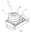
Figure 1 , a representative view where the subject matter invention is applied is given. - In
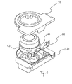
Figure 2 , the perspective view of the partially assembled form of the subject matter ignition switch is given. - In
Figure 3 , the perspective view of the dismantled form of the subject matter ignition switch is given. - In
Figure 4a , the perspective view of the ignition switch hub used in the subject matter invention is given. - In
Figure 4b , the perspective view of the first contact used in the subject matter invention is given. - In this detailed explanation, the subject matter ignition switch (30) is explained with references to the annexed figures without forming any restrictive effect in order to make the subject more understandable. Accordingly, in the detailed description below, the subject matter invention is assumed to be applied to a cooker with a gas stove or with a gas grill.
- In
Figure 1 , a gas tap (10) which controls the gas flow arriving a burner of a cooker (not illustrated in the figure) and which is connected to the gas collector pipe (20); and an ignition switch (30) which is connected to the rotary shaft (11) of said gas tap (10) are illustrated. Accordingly, when the user rotates a control button (not illustrated in the figure) fixed to the rotary shaft (11) in the opening direction, gas flow is realized to the related gas in proportion with the rotation amount, and at this instant, the ignition switch (30) provides electricity to the spark plug of the related burner for a certain duration, thus, flame is formed and thereby the gas in the burner is flamed. - With reference to
Figure 2 and3 , the subject matter gas tap (10) essentially comprises a switch chamber (31); a hub (40) which is positioned inside said switch chamber (31) in a rotatable manner and which has a shaft opening (41) wherein the rotary shaft (11) is placed so as to preferably form shape coupling; a second contact (50) which is connected in a fixed manner to one side of the switch chamber (31); and a movable first contact (60) which can change position and which is connected to the opposite side of the chamber (31). - The first contact member (60), which is preferably made of flexible metal, does not contact with the second contact (50) normally; and with the rotation of the hub (40) in clockwise direction or in anti-clockwise direction, the contact between the second contact member (50) and the first contact member (60) is controlled as detailed below. The ignition switch (30) moreover has a cover (32) which closes said switch chamber (31).
- With reference to
Figure 4a , the hub (40) has a first and a second tab (43, 44), which are preferably in radial form and which are positioned on the lateral surface (42) of the hub (40) so as to have a space in between. Each radial formed tab (43, 44) has a lateral cross section which is preferably in the form of a parallelogram and which is formed by giving an inclination at the edges thereof. - In more details, in a preferred embodiment of the subject matter invention, the second radial formed tab (43) has a second triggering member part (431) which extends in an angled manner so as to face the base part (45) of the hub (40); preferably the second curved part (432) which extends parallel to the ground; and a rear elevating member part (433) which extends in an angled manner so as to face the upper part (46) of the hub (40). In a similar manner, the second radial tab (44) comprises a first triggering member part (441) which extends in an angled manner so as to face the base part (45) of the hub (40); a first curved part (442) which extends parallel to the ground; and a rear elevating member part (433) which extends in an angled manner so as to face the upper part (46) of the hub (40). On the other hand, the first and the second radial tabs (43, 44) are positioned on the lateral surface (42) of the hub (40) so that the first and the second triggering member parts (431, 441) preferably face each other.
- With reference to
Figure 3 , the second contact member (50) is connected to the switch chamber (31) preferably from the left lower corner of the switch chamber (31) by means of the connection end (52) thereof; and the first contact member (60) is connected to the switch chamber (31) from the right lower corner of the switch chamber (31) by means of the connection end (52) thereof. After the connection is realized, the contact end (61) of the first contact member (60) is at the upper alignment of the contact end (51) of the second contact member (50). Respectively the electrical cables which are supplied from the ignition circuit and which arrive to the spark plug are connected to the cable housings (521, 621) formed at the connection end (52, 62) of each contact (50, 60). On the other hand, with reference toFigure 4b , the first contact (60) comprises an arm part (64) which extends at the continuation of the connection end (62); a flexible part (63) extending at the continuation of the arm part (64); and a contact end (61) extending at the continuation of the flexible part (63). - Said first contact member (60), which has the subject matter characteristics, comprises a rear flexible guide part (631) which extends upwardly in an angled manner at the continuation of the arm part (64); and a front flexible guide part (633) which extends as a flat surface in a parallel manner to the ground at the continuation of said rear flexible guide part (631), which forms the raised part (632) and which extends downwardly in an angled manner up to the contact end (61) at the continuation of said raised part (632).
- Under the light of the structural details given above, the operation of the subject matter invention is as follows. When the user rotates the control button in the clockwise direction for igniting for instance the burner of an oven, the second triggering member part (431) of the second radial tab (44) contacts with the rear guide flexible part (631) of the first contact member (60), thus, the first contact member (60) moves downwardly and it contacts with the second contact (50). As a result, the circuit is completed and the spark plug is ignited. Afterwards, the user continues to rotate the control button in the same direction and, accordingly, the first contact member (60) remains in contact with the second contact member (50) until preferably the flat first curved part (42) ends.
- In an exemplary application of the subject matter invention, the first contact member (60) has a cut-out rear groove part (611) which is provided at the beginning of the rear flexible guide part (631) at the arm part (64) and which provides the second tab's (43) elevating member part (433) to enter into the lower side of the first contact member (60) when the hub (40) is rotated from the gas applying position to the gas turning off position. At the part where this groove part (611) exists, the width of the arm part (64) is narrowed.
- Moreover, the first contact (60) has a cut-out front groove part (612) which is provided at the end of the front flexible guide part (633) and which provides the first tab's (44) elevating member part (443) to enter into the bottom part of the first contact member (60) when the hub (40) is rotated from the gas applying position to the gas turning off position. Thus, at the continuation of the flexible guide part (633), the width of the first contact member (60) is narrowed.
- Meanwhile, a burner is ignited which is for instance at the upper part of the oven. When the contact between the second curved part (432) and the first contact member (60) is broken, since the first contact member (60) is released from pressure, it bends upwardly and thereby it again returns to the prior position thereof, thus the circuit becomes open circuit. As can be understood from this, the length of the first curved part (442) determines the electricity application duration to the spark plug.
- For the turning off of the burner, when the user rotates the control button in counterclockwise direction, the first triggering member part (443) reaches the front groove part (612) adjacent to the contact end (61) of the first contact member (60), and from there, because of the form of the curved part (442), it enters under the first contact member (60) by means of a first triggering member part (443) whose surface faces the upper side. Thus, during rotation, a useless ignition process is prevented.
- In a similar manner, for instance, when the user rotates the control button for igniting a lower grill of the oven, a first triggering member part (441) of the second radial tab (43) facing downwardly contacts with the front flexible guide part (633) of the first contact member (60), thus, the first contact member (60) bends downwardly and it contacts with the second contact member (50). As a result of this, the circuit is completed and the spark plug is ignited.
- Afterwards, the user continues to rotate the control button in the same direction, accordingly, the first contact member (60) and the second contact member (50) remain in contact until the contact of the first contact member (60) with the second curved part (432) ends.
- The contact of the second curved part (432) with the first contact member (60) is broken, and thereby the first contact returns to the prior position and thus the circuit becomes open circuit. When the user rotates the control button for turning off the grill, the first triggering member part (443) reaches the rear groove part (611) of the first contact member (60), and from there, it enters under the lower side of the first contact member (60). Thus, again during this rotation, a useless ignition is prevented again.
-
- 10
- Gas tap
- 11
- Rotary shaft
- 20
- Gas collector pipe
- 30
- Ignition switch
- 31
- Switch chamber
- 32
- Cover
- 40
- Hub
- 41
- Shaft opening
- 42
- Lateral surface
- 43
- Second tab
- 431
- Second triggering member part
- 432
- Second curved part
- 433
- Second elevating member part
- 44
- First tab
- 441
- First triggering member part
- 442
- First curved part
- 443
- First elevating member part
- 45
- Base part
- 46
- Upper part
- 50
- Second contact member
- 51
- Contact end
- 52
- Connection end
- 521
- Cable housing
- 60
- First contact member
- 61
- Contact end
- 611
- Rear groove part
- 612
- Front groove part
- 62
- Connection end
- 621
- Cable housing
- 63
- Flexible part
- 631
- Rear flexible guide part
- 632
- Raised part
- 633
- Front flexible guide part
- 64
- Arm part
Claims (15)
- An ignition switch (30) comprising a switch chamber (31); a hub (40) which is positioned inside said switch chamber (31) in a rotatable manner and which is engaged and connected to the rotary shaft (11) of a gas tap (10) which provides gas to the gas cooking member; a first contact member (60) with an arm part (64) which is provided on said hub (40) and whose position is changeable during the opening and turning off of the gas tap, and with a contact end part (61) and with a flexible front guide part (633); a second contact member (50) which contacts with the end part (61) of said first contact member (60) when in opening direction of the gas tap (10); and a tab (44) which is provided on the lateral surface (42) of said hub (40) for changing the position of the first contact member (60) and which triggers ignition by contacting with this flexible front guide part (633), said ignition switch (30) is characterized by comprising at least one second tab (43) which is provided on the lateral surface (42) of the hub (40) which advances on said first contact member (60), in order to trigger the contact of the first contact member (60) to the second contact (50) for the ignition of the gas in a second gas cooking member.
- An ignition switch (30) according to claim 1, wherein, in order to provide ignition to at least two gas cooking members, there is at least one rear flexible guide part (631) to which a pushing force is applied by said tabs (43, 44) which contact at a second different point and which are formed between the contact end (61) and said arm part (64) on the first contact member (60).
- An ignition switch (30) according to claim 1, wherein a first tab (44) and a second tab (43) are provided which preferably have radial form.
- An ignition switch (30) according to any one of the preceding claims, wherein at least one triggering member part (431, 441) is provided which is preferably formed in the form of a cut-out and which provides the contact of the first contact member to the second contact member, which is provided on at least one tab (43, 44) by means of pushing; and a curved member part (432, 442) is provided which adjusts the duration of pressing of this tab to the first contact member.
- An ignition switch (30) according to claim 2, wherein at least one ramp-formed step is provided inside said rear flexible guide part (631) which is provided on the first contact member (60) which provides ignition with the contacting of said two tabs (43).
- An ignition switch (30) according to claim 1 and 3, wherein, in order to prevent the contact of said first contact member (60) to the second contact (50), there is at least one rear elevating member part (433, 443) which is provided on the tab (43, 44) and which is preferably formed in cut-out form.
- An ignition switch (30) according to claim 1, 3 and 5, wherein said second tab (43) comprises at least one triggering member part (431) in the gas applying direction; at least one elevating member part (432) in the gas turning off direction; and a curved member part (433) which determines at least one ignition duration.
- An ignition switch (30) according to claim 2 and 4, wherein, between front and rear two flexible guide parts (631, 633) of said first contact member (60) with two flexible front and rear guide parts (631, 633) igniting two gas cooking members, the front and rear flexible guide parts (631, 633) form the lateral edges of a trapezoid; and at least one raised part (632) is provided which is embodied preferably in a flat form on the upper edge of said trapezoid.
- An ignition switch (30) according to any one of the preceding claims, wherein preferably a predetermined distance is provided between the radial positions of said first and second tabs (43, 44) which are provided on the lateral surface of the hub.
- An ignition switch (30) according to any one of the preceding claims, wherein the orthogonal axial positions of said first and second tabs (43, 44) of said ignition switch are provided in a spaced manner.
- An ignition switch (30) according to any one of the preceding claims, wherein said first and second tabs' (43, 44) orthogonal axial positions on the lateral surface (42) are provided in the same radial direction.
- An ignition switch (30) according to any one of the preceding claims, wherein said first and second tabs (43, 44) preferably have a cross section in the form of a parallelogram.
- An ignition switch (30) according to any one of the preceding claims, wherein, the first contact member (60) has a cut-out rear groove part (611) which is provided at the beginning of the rear flexible guide part (631) at the arm part (64) and which provides the second tab's (43) elevating member part (433) to enter into the lower side of the first contact member (60) when the hub (40) is rotated from the gas applying position to the gas turning off position.
- An ignition switch (30) according to any one of the preceding claims, wherein, the first contact (60) has a cut-out front groove part (612) which is provided at the end of the front flexible guide part (633) and which provides the first tab's (44) elevating member part (443) to enter into the bottom part of the first contact member (60) when the hub (40) is rotated from the gas applying position to the gas turning off position.
- An ignition switch (30) according to any one of the preceding claims, wherein the subject matter invention is a gas oven wherein the ignition switch is to be used.
Applications Claiming Priority (1)
| Application Number | Priority Date | Filing Date | Title |
|---|---|---|---|
| TR2010/10995A TR201010995A2 (en) | 2010-12-28 | 2010-12-28 | One ignition switch for gas taps |
Publications (2)
| Publication Number | Publication Date |
|---|---|
| EP2472183A2 true EP2472183A2 (en) | 2012-07-04 |
| EP2472183A3 EP2472183A3 (en) | 2017-08-30 |
Family
ID=45442895
Family Applications (1)
| Application Number | Title | Priority Date | Filing Date |
|---|---|---|---|
| EP11194306.4A Ceased EP2472183A3 (en) | 2010-12-28 | 2011-12-19 | An ignition switch for gas taps |
Country Status (2)
| Country | Link |
|---|---|
| EP (1) | EP2472183A3 (en) |
| TR (1) | TR201010995A2 (en) |
Cited By (1)
| Publication number | Priority date | Publication date | Assignee | Title |
|---|---|---|---|---|
| CN111947149A (en) * | 2020-08-24 | 2020-11-17 | 宁波方太厨具有限公司 | Stove burner |
Citations (3)
| Publication number | Priority date | Publication date | Assignee | Title |
|---|---|---|---|---|
| US4019855A (en) | 1975-10-14 | 1977-04-26 | Illinois Tool Works Inc. | Electrical switch for ignition in gas appliances |
| TR200704647U (en) | 2007-07-03 | 2007-08-21 | Termal Elektroni̇k Ve Devre Elemanlari Sanayi̇i̇ Ti̇caret A.Ş. | Lighter switch for gas cookers and ovens. |
| EP2151836A2 (en) | 2008-08-06 | 2010-02-10 | Coprececitec, S.L. | Ignition switch assembly for a gas tap |
Family Cites Families (2)
| Publication number | Priority date | Publication date | Assignee | Title |
|---|---|---|---|---|
| US3971904A (en) * | 1973-10-23 | 1976-07-27 | Illinois Tool Works Inc. | Switch assembly for gas tap assembly having cam operated leaf spring contacts and split housing cam detent stop |
| FR2335933A1 (en) * | 1975-12-17 | 1977-07-15 | Bonhoure Raymond | Low current capability rotary switch for lighting circuits - has grooved drum operating spring strip with moving contact |
-
2010
- 2010-12-28 TR TR2010/10995A patent/TR201010995A2/en unknown
-
2011
- 2011-12-19 EP EP11194306.4A patent/EP2472183A3/en not_active Ceased
Patent Citations (3)
| Publication number | Priority date | Publication date | Assignee | Title |
|---|---|---|---|---|
| US4019855A (en) | 1975-10-14 | 1977-04-26 | Illinois Tool Works Inc. | Electrical switch for ignition in gas appliances |
| TR200704647U (en) | 2007-07-03 | 2007-08-21 | Termal Elektroni̇k Ve Devre Elemanlari Sanayi̇i̇ Ti̇caret A.Ş. | Lighter switch for gas cookers and ovens. |
| EP2151836A2 (en) | 2008-08-06 | 2010-02-10 | Coprececitec, S.L. | Ignition switch assembly for a gas tap |
Cited By (1)
| Publication number | Priority date | Publication date | Assignee | Title |
|---|---|---|---|---|
| CN111947149A (en) * | 2020-08-24 | 2020-11-17 | 宁波方太厨具有限公司 | Stove burner |
Also Published As
| Publication number | Publication date |
|---|---|
| TR201010995A2 (en) | 2012-07-23 |
| EP2472183A3 (en) | 2017-08-30 |
Similar Documents
| Publication | Publication Date | Title |
|---|---|---|
| US7902476B2 (en) | Ignition switch assembly for a gas valve | |
| US5525771A (en) | Spark ignition switch and valve assembly for gas burners including external detent assembly | |
| EP2472183A2 (en) | An ignition switch for gas taps | |
| US10082295B2 (en) | Gas heating arrangement and method for operating a gas heating arrangement | |
| EP2827060A1 (en) | Cam gas tap with a plug and integrated cam for domestic cooking appliances | |
| US3436165A (en) | Spark ignition device with a gas control valve and a switch | |
| EP2423593A2 (en) | Cam disc operating the ignition modules | |
| KR101364728B1 (en) | An ignition apparatus of gas burner for restaurant | |
| EP1798471B1 (en) | Microswitch assembly which can be associated to a gas cock, in particular for cooktops and the like | |
| EP1907756B1 (en) | A cooking device | |
| EP2574843A1 (en) | A time adjusted mechanical gas shut-off system | |
| KR101864961B1 (en) | Valve for cooktop | |
| KR101018332B1 (en) | Auto ignite implement of gas equipment | |
| EP3839351A1 (en) | Switch assembly for controlling the ignition of gas burners of a cooking appliance | |
| CN215175267U (en) | Stove ignition control system and stove | |
| CN215909110U (en) | Timing switch device and gas stove | |
| CN115751402A (en) | Temperature control valve | |
| CN218763538U (en) | Gas kitchen ranges | |
| CN219588168U (en) | Ignition valve and gas stove | |
| CN112032358A (en) | Gas stove regulating valve and gas stove | |
| CN112728592B (en) | Plug valve and gas stove | |
| CN111750384B (en) | Gas stove capable of preventing extinguishing and switching gas | |
| EP2708815A2 (en) | A gas tap for touch-sensitive gas control systems | |
| CN217114229U (en) | Temperature control switch for high-temperature household appliance | |
| JP2734869B2 (en) | Automatic temperature control mechanism of oil stove |
Legal Events
| Date | Code | Title | Description |
|---|---|---|---|
| AK | Designated contracting states |
Kind code of ref document: A2 Designated state(s): AL AT BE BG CH CY CZ DE DK EE ES FI FR GB GR HR HU IE IS IT LI LT LU LV MC MK MT NL NO PL PT RO RS SE SI SK SM TR |
|
| AX | Request for extension of the european patent |
Extension state: BA ME |
|
| PUAI | Public reference made under article 153(3) epc to a published international application that has entered the european phase |
Free format text: ORIGINAL CODE: 0009012 |
|
| RAP1 | Party data changed (applicant data changed or rights of an application transferred) |
Owner name: BSH HAUSGERAETE GMBH |
|
| PUAL | Search report despatched |
Free format text: ORIGINAL CODE: 0009013 |
|
| AK | Designated contracting states |
Kind code of ref document: A3 Designated state(s): AL AT BE BG CH CY CZ DE DK EE ES FI FR GB GR HR HU IE IS IT LI LT LU LV MC MK MT NL NO PL PT RO RS SE SI SK SM TR |
|
| AX | Request for extension of the european patent |
Extension state: BA ME |
|
| RIC1 | Information provided on ipc code assigned before grant |
Ipc: F24C 3/10 20060101AFI20170727BHEP Ipc: H01H 19/63 20060101ALI20170727BHEP Ipc: H01H 3/02 20060101ALI20170727BHEP |
|
| 17P | Request for examination filed |
Effective date: 20180228 |
|
| RBV | Designated contracting states (corrected) |
Designated state(s): AL AT BE BG CH CY CZ DE DK EE ES FI FR GB GR HR HU IE IS IT LI LT LU LV MC MK MT NL NO PL PT RO RS SE SI SK SM TR |
|
| 17Q | First examination report despatched |
Effective date: 20180907 |
|
| STAA | Information on the status of an ep patent application or granted ep patent |
Free format text: STATUS: THE APPLICATION HAS BEEN REFUSED |
|
| 18R | Application refused |
Effective date: 20190113 |