EP4394244A1 - Lamp comprinsing an inner lens - Google Patents
Lamp comprinsing an inner lens Download PDFInfo
- Publication number
- EP4394244A1 EP4394244A1 EP23183537.2A EP23183537A EP4394244A1 EP 4394244 A1 EP4394244 A1 EP 4394244A1 EP 23183537 A EP23183537 A EP 23183537A EP 4394244 A1 EP4394244 A1 EP 4394244A1
- Authority
- EP
- European Patent Office
- Prior art keywords
- optic
- output
- area
- lamp
- back cover
- Prior art date
- Legal status (The legal status is an assumption and is not a legal conclusion. Google has not performed a legal analysis and makes no representation as to the accuracy of the status listed.)
- Granted
Links
Images


Classifications
-
- F—MECHANICAL ENGINEERING; LIGHTING; HEATING; WEAPONS; BLASTING
- F21—LIGHTING
- F21S—NON-PORTABLE LIGHTING DEVICES; SYSTEMS THEREOF; VEHICLE LIGHTING DEVICES SPECIALLY ADAPTED FOR VEHICLE EXTERIORS
- F21S43/00—Signalling devices specially adapted for vehicle exteriors, e.g. brake lamps, direction indicator lights or reversing lights
- F21S43/20—Signalling devices specially adapted for vehicle exteriors, e.g. brake lamps, direction indicator lights or reversing lights characterised by refractors, transparent cover plates, light guides or filters
-
- F—MECHANICAL ENGINEERING; LIGHTING; HEATING; WEAPONS; BLASTING
- F21—LIGHTING
- F21S—NON-PORTABLE LIGHTING DEVICES; SYSTEMS THEREOF; VEHICLE LIGHTING DEVICES SPECIALLY ADAPTED FOR VEHICLE EXTERIORS
- F21S43/00—Signalling devices specially adapted for vehicle exteriors, e.g. brake lamps, direction indicator lights or reversing lights
- F21S43/20—Signalling devices specially adapted for vehicle exteriors, e.g. brake lamps, direction indicator lights or reversing lights characterised by refractors, transparent cover plates, light guides or filters
- F21S43/26—Refractors, transparent cover plates, light guides or filters not provided in groups F21S43/235 - F21S43/255
-
- F—MECHANICAL ENGINEERING; LIGHTING; HEATING; WEAPONS; BLASTING
- F21—LIGHTING
- F21S—NON-PORTABLE LIGHTING DEVICES; SYSTEMS THEREOF; VEHICLE LIGHTING DEVICES SPECIALLY ADAPTED FOR VEHICLE EXTERIORS
- F21S43/00—Signalling devices specially adapted for vehicle exteriors, e.g. brake lamps, direction indicator lights or reversing lights
- F21S43/10—Signalling devices specially adapted for vehicle exteriors, e.g. brake lamps, direction indicator lights or reversing lights characterised by the light source
- F21S43/13—Signalling devices specially adapted for vehicle exteriors, e.g. brake lamps, direction indicator lights or reversing lights characterised by the light source characterised by the type of light source
- F21S43/14—Light emitting diodes [LED]
-
- F—MECHANICAL ENGINEERING; LIGHTING; HEATING; WEAPONS; BLASTING
- F21—LIGHTING
- F21S—NON-PORTABLE LIGHTING DEVICES; SYSTEMS THEREOF; VEHICLE LIGHTING DEVICES SPECIALLY ADAPTED FOR VEHICLE EXTERIORS
- F21S43/00—Signalling devices specially adapted for vehicle exteriors, e.g. brake lamps, direction indicator lights or reversing lights
- F21S43/10—Signalling devices specially adapted for vehicle exteriors, e.g. brake lamps, direction indicator lights or reversing lights characterised by the light source
- F21S43/13—Signalling devices specially adapted for vehicle exteriors, e.g. brake lamps, direction indicator lights or reversing lights characterised by the light source characterised by the type of light source
- F21S43/15—Strips of light sources
-
- F—MECHANICAL ENGINEERING; LIGHTING; HEATING; WEAPONS; BLASTING
- F21—LIGHTING
- F21S—NON-PORTABLE LIGHTING DEVICES; SYSTEMS THEREOF; VEHICLE LIGHTING DEVICES SPECIALLY ADAPTED FOR VEHICLE EXTERIORS
- F21S43/00—Signalling devices specially adapted for vehicle exteriors, e.g. brake lamps, direction indicator lights or reversing lights
- F21S43/10—Signalling devices specially adapted for vehicle exteriors, e.g. brake lamps, direction indicator lights or reversing lights characterised by the light source
- F21S43/19—Attachment of light sources or lamp holders
-
- F—MECHANICAL ENGINEERING; LIGHTING; HEATING; WEAPONS; BLASTING
- F21—LIGHTING
- F21S—NON-PORTABLE LIGHTING DEVICES; SYSTEMS THEREOF; VEHICLE LIGHTING DEVICES SPECIALLY ADAPTED FOR VEHICLE EXTERIORS
- F21S43/00—Signalling devices specially adapted for vehicle exteriors, e.g. brake lamps, direction indicator lights or reversing lights
- F21S43/20—Signalling devices specially adapted for vehicle exteriors, e.g. brake lamps, direction indicator lights or reversing lights characterised by refractors, transparent cover plates, light guides or filters
- F21S43/2605—Refractors
- F21S43/2621—Refractors characterised by the properties of the light beam shaping surface
- F21S43/26241—Refractors characterised by the properties of the light beam shaping surface diffusing, scattering or spreading
-
- F—MECHANICAL ENGINEERING; LIGHTING; HEATING; WEAPONS; BLASTING
- F21—LIGHTING
- F21S—NON-PORTABLE LIGHTING DEVICES; SYSTEMS THEREOF; VEHICLE LIGHTING DEVICES SPECIALLY ADAPTED FOR VEHICLE EXTERIORS
- F21S43/00—Signalling devices specially adapted for vehicle exteriors, e.g. brake lamps, direction indicator lights or reversing lights
- F21S43/20—Signalling devices specially adapted for vehicle exteriors, e.g. brake lamps, direction indicator lights or reversing lights characterised by refractors, transparent cover plates, light guides or filters
- F21S43/2605—Refractors
- F21S43/2641—Refractors or refracting portions characterised by their relative arrangement, e.g. parallel refractors
- F21S43/26411—Two or more successive refractors
-
- F—MECHANICAL ENGINEERING; LIGHTING; HEATING; WEAPONS; BLASTING
- F21—LIGHTING
- F21S—NON-PORTABLE LIGHTING DEVICES; SYSTEMS THEREOF; VEHICLE LIGHTING DEVICES SPECIALLY ADAPTED FOR VEHICLE EXTERIORS
- F21S43/00—Signalling devices specially adapted for vehicle exteriors, e.g. brake lamps, direction indicator lights or reversing lights
- F21S43/20—Signalling devices specially adapted for vehicle exteriors, e.g. brake lamps, direction indicator lights or reversing lights characterised by refractors, transparent cover plates, light guides or filters
- F21S43/265—Transparent cover plates, e.g. for protecting the interior of the signalling devices against environmental influences
-
- F—MECHANICAL ENGINEERING; LIGHTING; HEATING; WEAPONS; BLASTING
- F21—LIGHTING
- F21S—NON-PORTABLE LIGHTING DEVICES; SYSTEMS THEREOF; VEHICLE LIGHTING DEVICES SPECIALLY ADAPTED FOR VEHICLE EXTERIORS
- F21S43/00—Signalling devices specially adapted for vehicle exteriors, e.g. brake lamps, direction indicator lights or reversing lights
- F21S43/30—Signalling devices specially adapted for vehicle exteriors, e.g. brake lamps, direction indicator lights or reversing lights characterised by reflectors
- F21S43/31—Optical layout thereof
-
- F—MECHANICAL ENGINEERING; LIGHTING; HEATING; WEAPONS; BLASTING
- F21—LIGHTING
- F21S—NON-PORTABLE LIGHTING DEVICES; SYSTEMS THEREOF; VEHICLE LIGHTING DEVICES SPECIALLY ADAPTED FOR VEHICLE EXTERIORS
- F21S43/00—Signalling devices specially adapted for vehicle exteriors, e.g. brake lamps, direction indicator lights or reversing lights
- F21S43/30—Signalling devices specially adapted for vehicle exteriors, e.g. brake lamps, direction indicator lights or reversing lights characterised by reflectors
- F21S43/31—Optical layout thereof
- F21S43/315—Optical layout thereof using total internal reflection
-
- F—MECHANICAL ENGINEERING; LIGHTING; HEATING; WEAPONS; BLASTING
- F21—LIGHTING
- F21S—NON-PORTABLE LIGHTING DEVICES; SYSTEMS THEREOF; VEHICLE LIGHTING DEVICES SPECIALLY ADAPTED FOR VEHICLE EXTERIORS
- F21S43/00—Signalling devices specially adapted for vehicle exteriors, e.g. brake lamps, direction indicator lights or reversing lights
- F21S43/30—Signalling devices specially adapted for vehicle exteriors, e.g. brake lamps, direction indicator lights or reversing lights characterised by reflectors
- F21S43/33—Signalling devices specially adapted for vehicle exteriors, e.g. brake lamps, direction indicator lights or reversing lights characterised by reflectors characterised by their material, surface treatment or coatings
-
- F—MECHANICAL ENGINEERING; LIGHTING; HEATING; WEAPONS; BLASTING
- F21—LIGHTING
- F21S—NON-PORTABLE LIGHTING DEVICES; SYSTEMS THEREOF; VEHICLE LIGHTING DEVICES SPECIALLY ADAPTED FOR VEHICLE EXTERIORS
- F21S43/00—Signalling devices specially adapted for vehicle exteriors, e.g. brake lamps, direction indicator lights or reversing lights
- F21S43/30—Signalling devices specially adapted for vehicle exteriors, e.g. brake lamps, direction indicator lights or reversing lights characterised by reflectors
- F21S43/33—Signalling devices specially adapted for vehicle exteriors, e.g. brake lamps, direction indicator lights or reversing lights characterised by reflectors characterised by their material, surface treatment or coatings
- F21S43/332—Diffusing reflectors
-
- F—MECHANICAL ENGINEERING; LIGHTING; HEATING; WEAPONS; BLASTING
- F21—LIGHTING
- F21S—NON-PORTABLE LIGHTING DEVICES; SYSTEMS THEREOF; VEHICLE LIGHTING DEVICES SPECIALLY ADAPTED FOR VEHICLE EXTERIORS
- F21S43/00—Signalling devices specially adapted for vehicle exteriors, e.g. brake lamps, direction indicator lights or reversing lights
- F21S43/40—Signalling devices specially adapted for vehicle exteriors, e.g. brake lamps, direction indicator lights or reversing lights characterised by the combination of reflectors and refractors
-
- F—MECHANICAL ENGINEERING; LIGHTING; HEATING; WEAPONS; BLASTING
- F21—LIGHTING
- F21S—NON-PORTABLE LIGHTING DEVICES; SYSTEMS THEREOF; VEHICLE LIGHTING DEVICES SPECIALLY ADAPTED FOR VEHICLE EXTERIORS
- F21S43/00—Signalling devices specially adapted for vehicle exteriors, e.g. brake lamps, direction indicator lights or reversing lights
- F21S43/40—Signalling devices specially adapted for vehicle exteriors, e.g. brake lamps, direction indicator lights or reversing lights characterised by the combination of reflectors and refractors
- F21S43/401—Signalling devices specially adapted for vehicle exteriors, e.g. brake lamps, direction indicator lights or reversing lights characterised by the combination of reflectors and refractors the refractors and the reflectors being distinct parts
-
- F—MECHANICAL ENGINEERING; LIGHTING; HEATING; WEAPONS; BLASTING
- F21—LIGHTING
- F21S—NON-PORTABLE LIGHTING DEVICES; SYSTEMS THEREOF; VEHICLE LIGHTING DEVICES SPECIALLY ADAPTED FOR VEHICLE EXTERIORS
- F21S43/00—Signalling devices specially adapted for vehicle exteriors, e.g. brake lamps, direction indicator lights or reversing lights
- F21S43/50—Signalling devices specially adapted for vehicle exteriors, e.g. brake lamps, direction indicator lights or reversing lights characterised by aesthetic components not otherwise provided for, e.g. decorative trim, partition walls or covers
-
- F—MECHANICAL ENGINEERING; LIGHTING; HEATING; WEAPONS; BLASTING
- F21—LIGHTING
- F21S—NON-PORTABLE LIGHTING DEVICES; SYSTEMS THEREOF; VEHICLE LIGHTING DEVICES SPECIALLY ADAPTED FOR VEHICLE EXTERIORS
- F21S45/00—Arrangements within vehicle lighting devices specially adapted for vehicle exteriors, for purposes other than emission or distribution of light
- F21S45/10—Protection of lighting devices
-
- F—MECHANICAL ENGINEERING; LIGHTING; HEATING; WEAPONS; BLASTING
- F21—LIGHTING
- F21V—FUNCTIONAL FEATURES OR DETAILS OF LIGHTING DEVICES OR SYSTEMS THEREOF; STRUCTURAL COMBINATIONS OF LIGHTING DEVICES WITH OTHER ARTICLES, NOT OTHERWISE PROVIDED FOR
- F21V15/00—Protecting lighting devices from damage
- F21V15/01—Housings, e.g. material or assembling of housing parts
-
- F—MECHANICAL ENGINEERING; LIGHTING; HEATING; WEAPONS; BLASTING
- F21—LIGHTING
- F21V—FUNCTIONAL FEATURES OR DETAILS OF LIGHTING DEVICES OR SYSTEMS THEREOF; STRUCTURAL COMBINATIONS OF LIGHTING DEVICES WITH OTHER ARTICLES, NOT OTHERWISE PROVIDED FOR
- F21V19/00—Fastening of light sources or lamp holders
-
- F—MECHANICAL ENGINEERING; LIGHTING; HEATING; WEAPONS; BLASTING
- F21—LIGHTING
- F21V—FUNCTIONAL FEATURES OR DETAILS OF LIGHTING DEVICES OR SYSTEMS THEREOF; STRUCTURAL COMBINATIONS OF LIGHTING DEVICES WITH OTHER ARTICLES, NOT OTHERWISE PROVIDED FOR
- F21V5/00—Refractors for light sources
- F21V5/04—Refractors for light sources of lens shape
-
- F—MECHANICAL ENGINEERING; LIGHTING; HEATING; WEAPONS; BLASTING
- F21—LIGHTING
- F21V—FUNCTIONAL FEATURES OR DETAILS OF LIGHTING DEVICES OR SYSTEMS THEREOF; STRUCTURAL COMBINATIONS OF LIGHTING DEVICES WITH OTHER ARTICLES, NOT OTHERWISE PROVIDED FOR
- F21V7/00—Reflectors for light sources
- F21V7/0091—Reflectors for light sources using total internal reflection
-
- F—MECHANICAL ENGINEERING; LIGHTING; HEATING; WEAPONS; BLASTING
- F21—LIGHTING
- F21V—FUNCTIONAL FEATURES OR DETAILS OF LIGHTING DEVICES OR SYSTEMS THEREOF; STRUCTURAL COMBINATIONS OF LIGHTING DEVICES WITH OTHER ARTICLES, NOT OTHERWISE PROVIDED FOR
- F21V7/00—Reflectors for light sources
- F21V7/22—Reflectors for light sources characterised by materials, surface treatments or coatings, e.g. dichroic reflectors
- F21V7/24—Reflectors for light sources characterised by materials, surface treatments or coatings, e.g. dichroic reflectors characterised by the material
-
- F—MECHANICAL ENGINEERING; LIGHTING; HEATING; WEAPONS; BLASTING
- F21—LIGHTING
- F21W—INDEXING SCHEME ASSOCIATED WITH SUBCLASSES F21K, F21L, F21S and F21V, RELATING TO USES OR APPLICATIONS OF LIGHTING DEVICES OR SYSTEMS
- F21W2103/00—Exterior vehicle lighting devices for signalling purposes
-
- F—MECHANICAL ENGINEERING; LIGHTING; HEATING; WEAPONS; BLASTING
- F21—LIGHTING
- F21W—INDEXING SCHEME ASSOCIATED WITH SUBCLASSES F21K, F21L, F21S and F21V, RELATING TO USES OR APPLICATIONS OF LIGHTING DEVICES OR SYSTEMS
- F21W2107/00—Use or application of lighting devices on or in particular types of vehicles
- F21W2107/10—Use or application of lighting devices on or in particular types of vehicles for land vehicles
Definitions
- the light beam may be uniformly output toward the target direction from the output surface of the lens even without such an air gap, and thus the needs for lamps having minimized volumes are increasing.
- An aspect of the present disclosure provides a lamp which may output a light beam in a targeted direction without an air gap, and thus has a minimized volume.
- a lamp may be provided in which a plurality of output optic grooves retracted in a second direction and arranged to be spaced apart from each other may be formed in the output area.
- a lamp may be provided in which the inner lens may further include an optic area through which the light beam output from the light source part is input, passes, and is then output to the reflective area, and the optic area may have a concave shape in a second direction.
- a lamp may be provided in which the cover body may obliquely extend such that an upper side thereof is inclined toward the second direction with respect to a vertical direction, the back cover optic may be provided as a plurality of back cover optics, and the plurality of back cover optics may be arranged to be spaced apart from each other.
- a lamp may be provided in which lengths, by which the cover bodies of the plurality of back cover optics protrude in the first direction from sides thereof in the first direction, are the same.
- a lamp may be provided in which a length by which first cover bodies of some of the plurality of back cover optics protrude in the first direction from sides thereof in the first direction may be different from a length by which first cover bodies of the others of the plurality of back cover optics protrude in the first direction from sides thereof in the first direction.
- a lamp may be provided in which, when the lamp is viewed in a direction perpendicular to the first direction and a vertical direction, at least a portion of the back cover optic and at least a portion of the reflective area may overlap each other.
- a lamp may be provided in which, when the back cover optic is viewed in the second direction, the back cover optic has one or more among a circular shape and polygonal shapes.
- the lamp 10 may provide information to an outside person.
- the lamp 10 may be a rear lamp provided on a rear side of a vehicle.
- the lamp 10 may include a light source part 100, a lens part 200, a back cover 300a, a frame 400, and a bezel 500.
- the light source part 100 may include a printed circuit board 110 and a light source 120.
- the printed circuit board 110 may be electrically connected to the light source 120.
- the printed circuit board 110 may be a printed circuit board (PCB).
- the printed circuit board 110 may have a band shape extending along the lens part 200.
- the printed circuit board 110 may be disposed to face the back cover 300a and the bezel 500.
- a side surface of the printed circuit board 110 in a first direction L1 may be disposed to face the bezel 500
- a side surface of the printed circuit board 110 in a second direction L2 may be disposed to face the back cover 300a.
- the first direction L1 may be defined as a traveling direction of a light beam output from the lamp 10.
- the light source 120 may output a light beam.
- the light source 120 may be provided with a first surface disposed on the side surface of the printed circuit board 110 in the second direction L2. Further, the light source 120 may be provided with a second surface disposed to face the back cover 300a.
- the first surface of the light source 120 may be in close contact with the printed circuit board 110, and the second surface of the light source 120 may be disposed to face the back cover 300a.
- the inner lens 210 may output the light beam output from the light source 120 to the outer lens 220.
- the inner lens 210 may be disposed between the outer lens 220 and the back cover 300a.
- the inner lens 210 may be disposed closer to the second direction L2 than the outer lens 220 and disposed closer to the first direction L1 than the back cover 300a.
- the inner lens 210 may be fastened to the back cover 300a.
- the light beam passing through the reflective area 212 may reach the back cover 300a.
- the back cover 300a may form an exterior of the lamp 10 in the second direction L2.
- the back cover 300a may be supported by the frame 400. Further, the back cover 300a may support the inner lens 210.
- the back cover 300a may include the cover body 310 and the back cover optic 320a.
- the back cover optic 320a may be provided on the surface of the cover body 310 in the first direction L1.
- the back cover optic 320a may have a shape protruding in the first direction L1 from the surface of the cover body 310 in the first direction L1.
- a length by which the back cover optic 320a protrudes in the first direction L1 from the surface of the cover body 310 in the first direction L1 may be named the protrusion length "d.”
- a separation distance between the back cover optic 320a and the optic area 211 in the first direction L1 may be smaller than the width of the inner lens 210.
- the width of the back cover optic 320a may be a width in a direction perpendicular to the inclination direction and the left-right direction.
- a protrusion length of some of the plurality of back cover optics 320a-1 may differ from a protrusion length of other thereof.
- the plurality of back cover optics 320a-1 may include a first back cover optic 321a, a second back cover optic 322a, and a third back cover optic 323a.
- the back cover 300b may include the cover body 310 and a back cover optic 320b.
- the cover body 310 refers to the description in the first embodiment.
- the back cover optic 320b may have a triangular shape.
- the back cover optic 320b may have an equilateral triangular shape.
- a size of the back cover optic 320b may be greater than a size of the output optic groove 213b-1.
- a length of one side of the triangular shape of the back cover optic 320b may be greater than a length of one side of the triangular shape of the output optic groove 213b-1.
- the back cover optic 320b may be provided as a plurality of back cover optics 320b.
- the plurality of back cover optics 320b may be arranged to be spaced apart from each other in the inclination direction.
- the output optic groove 213d-1 may be a groove recessed in the second direction L2 from an end of the output area 213d in the first direction L1. Further, the output optic groove 213d-1 may have a triangular pyramid shape. For example, when the output area 213d is viewed in the first direction L1, the output optic groove 213d-1 may have a quadrangular shape. Further, when the output area 213b is viewed in the vertical direction "H,” the output optic groove 213d-1 may have a triangular shape.
- the output optic groove 213d-1 may be provided as a plurality of output optic grooves 213d-1. The plurality of output optic grooves 213d-1 may be arranged to be adjacent to each other. For example, the plurality of output optic grooves 213d-1 may be arranged in a lattice pattern.
- the back cover optic 320d may have a triangular pyramid shape. For example, when the back cover optic 320d is viewed in the second direction L2, the back cover optic 320d may have a quadrangular shape. Further, when the back cover optic 320d is viewed in the vertical direction "H,” the back cover optic 320d may have a triangular shape.
Landscapes
- Engineering & Computer Science (AREA)
- General Engineering & Computer Science (AREA)
- Physics & Mathematics (AREA)
- Microelectronics & Electronic Packaging (AREA)
- Optics & Photonics (AREA)
- Non-Portable Lighting Devices Or Systems Thereof (AREA)
Abstract
Description
- This application claims the benefit of priority to
Korean Patent Application No. 10-2022-0184910, filed in the Korean Intellectual Property Office on December 26, 2022 - The present disclosure relates to a lamp.
- In general, a rear lamp provided on a rear side of a vehicle serves to provide information to an outside person. Such a lamp is provided with a light source that outputs a light beam and a lens that outputs the light beam output from the light source. The light beam output from the light source is diffused until the light beam reaches the lens, and the diffused light beam passes through the lens and is then output to the outside. In such a lens, a traveling direction of the light beam is changed so that the light beam passing through the lens is directed toward a target direction (for example, a rearward direction). In this case, the light beam output from the light source needs to be sufficiently spread so that the light beam may be uniformly output from upper and lower areas of an output surface of the lens.
- A lamp according to the related art is manufactured such that an air gap is formed between the lens and the light source so that the light beam output from the light source may be sufficiently spread until the light beam reaches the lens. Meanwhile, to form such an air gap, the lens and the light source should be arranged to be spaced a predetermined distance from each other. Such a lamp should be manufactured to have a large volume to have the air gap, and in a vehicle provided with the lamp having a large volume, space efficiency is degraded.
- Thus, in recent years, the light beam may be uniformly output toward the target direction from the output surface of the lens even without such an air gap, and thus the needs for lamps having minimized volumes are increasing.
- The present disclosure has been made to solve the above-mentioned problems occurring in the prior art while advantages achieved by the prior art are maintained intact.
- An aspect of the present disclosure provides a lamp which may output a light beam in a targeted direction without an air gap, and thus has a minimized volume.
- The technical problems to be solved by the present disclosure are not limited to the aforementioned problems, and any other technical problems not mentioned herein will be clearly understood from the following description by those skilled in the art to which the present disclosure pertains.
- According to an aspect of the present disclosure, there is provided a lamp that outputs a light beam to an outside in a first direction, the lamp including a light source part that outputs the light beam, and an inner lens including a reflective area that reflects the light beam output from the light source part and an output area that outputs the light beam reflected by the reflective area in the first direction and is disposed closer to the first direction than the reflective area.
- Further, a lamp may be provided in which the output area may be disposed at an end of the light source part in the first direction.
- Further, a lamp may be provided in which a side of the reflective area in the first direction and a side of the output area in a second direction opposite to the first direction may face each other.
- Further, a lamp may be provided in which a plurality of output optic grooves retracted in a second direction and arranged to be spaced apart from each other may be formed in the output area.
- Further, a lamp may be provided in which, when the plurality of output optic grooves are viewed in the first direction, the plurality of output optic grooves may have one or more shapes among a circular shape and polygonal shapes.
- Further, a lamp may be provided in which the inner lens may further include an optic area through which the light beam output from the light source part is input, passes, and is then output to the reflective area, and the optic area may have a concave shape in a second direction.
- Further, a lamp may be provided in which the optic area, the reflective area, and the output area may be integrally formed.
- Further, a lamp may be provided in which the light source part may include a printed circuit board extending along the inner lens, and a plurality of light sources arranged on a side of the printed circuit board in the second direction to be spaced apart from each other in a direction in which the printed circuit board extends, and the optic area may be provided as a plurality of optic areas to surround the plurality of light sources, respectively.
- Further, a lamp may be provided in which an end of the optic area in the second direction may extend in a vertical direction.
- Further, a lamp may be provided in which an upper portion of the optic area may extend from an upper end of an end in the second direction toward the output area in the first direction by a first length, a lower portion of the optic area may extend from a lower end of the end of the optic area in the second direction toward the output area in the first direction by a second length, and the first length may be smaller than the second length.
- Further, a lamp may be provided in which the lamp may further include a back cover that surrounds a side of the inner lens in a second direction, wherein the back cover includes a cover body of which a side in the first direction faces a side of the reflective area in the second direction, and a back cover optic protruding in the first direction from a side of the cover body in the first direction.
- Further, a lamp may be provided in which the cover body may obliquely extend such that an upper side thereof is inclined toward the second direction with respect to a vertical direction, the back cover optic may be provided as a plurality of back cover optics, and the plurality of back cover optics may be arranged to be spaced apart from each other.
- Further, a lamp may be provided in which lengths, by which the cover bodies of the plurality of back cover optics protrude in the first direction from sides thereof in the first direction, are the same.
- Further, a lamp may be provided in which a length by which first cover bodies of some of the plurality of back cover optics protrude in the first direction from sides thereof in the first direction may be different from a length by which first cover bodies of the others of the plurality of back cover optics protrude in the first direction from sides thereof in the first direction.
- Further, a lamp may be provided in which a gap having a width in the first direction that is smaller than a length by which the back cover optic protrudes from a side thereof in the first direction toward the reflective area may be formed between the side of the cover body in the first direction and the reflective area.
- Further, a lamp may be provided in which a portion of the light beam that is output from the light source part and reaches the reflective area may be reflected in the first direction and the other thereof may pass through the reflective area, and the light beam passing through the reflective area may pass through the gap and may be then diffused from the first direction on a surface of the cover body.
- Further, a lamp may be provided in which a reflective material may be deposited on a surface of the back cover optic in the first direction.
- Further, a lamp may be provided in which the reflective material may include an aluminum material.
- Further, a lamp may be provided in which, when the lamp is viewed in a direction perpendicular to the first direction and a vertical direction, at least a portion of the back cover optic and at least a portion of the reflective area may overlap each other.
- Further, a lamp may be provided in which, when the back cover optic is viewed in the second direction, the back cover optic has one or more among a circular shape and polygonal shapes.
- The above and other objects, features and advantages of the present disclosure will be more apparent from the following detailed description taken in conjunction with the accompanying drawings:
-
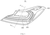
FIG. 1 is a perspective view of a lamp according to a first embodiment of the present disclosure; -
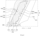
FIG. 2 is a longitudinal cross-sectional view along line A-A' ofFIG. 1 ; -
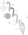
FIG. 3 is an exploded perspective view of the lamp according to the first embodiment of the present disclosure; -
FIG. 4 is a cross-sectional perspective view of a back cover according to the first embodiment of the present disclosure; -
FIG. 5 is a cross-sectional perspective view of a back cover according to a first modification of the present disclosure; -
FIG. 6 is an exploded perspective view of the lamp according to a second embodiment of the present disclosure; -
FIG. 7 is an exploded perspective view of the lamp according to a third embodiment of the present disclosure; -
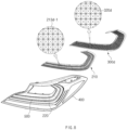
FIG. 8 is an exploded perspective view of the lamp according to a fourth embodiment of the present disclosure; -
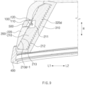
FIG. 9 is a longitudinal cross-sectional view of the lamp according to the fourth embodiment of the present disclosure; and -
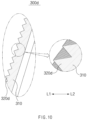
FIG. 10 is a cross-sectional perspective view of a back cover according to the fourth embodiment of the present disclosure. - Hereinafter, some embodiments of the present disclosure will be described in detail with reference to the exemplary drawings. In adding reference numerals to components of each drawing, it should be noted that identical or equivalent components are designated by an identical numeral even when they are displayed on other drawings. Further, in describing the embodiment of the present disclosure, a detailed description of the related known configuration or function will be omitted when it is determined that it interferes with the understanding of the embodiment of the present disclosure.
- Further, in the description of components of the embodiments of the present disclosure, the terms such as first, second, A, B, (a) and (b) may be used. These terms are merely intended to distinguish one component from other components, and the terms do not limit the nature, order, or sequence of the components. When it is described that one component "is input into", "is reflected by", "is output from", or "passes through" another component, the component may be directly input into, be directly reflected by, be directly output from, or directly pass through the other component, but a third component may "be input", "be reflected", "be output", or "pass" between the components.
- Hereinafter, a
lamp 10 according to a first embodiment will be described with reference to the accompanying drawings. - The
lamp 10 may provide information to an outside person. As an example, thelamp 10 may be a rear lamp provided on a rear side of a vehicle. Referring toFIGS. 1 to 3 , thelamp 10 may include alight source part 100, alens part 200, aback cover 300a, aframe 400, and abezel 500. - The
light source part 100 may include a printedcircuit board 110 and alight source 120. Referring back toFIG. 2 , the printedcircuit board 110 may be electrically connected to thelight source 120. Theprinted circuit board 110 may be a printed circuit board (PCB). The printedcircuit board 110 may have a band shape extending along thelens part 200. Further, the printedcircuit board 110 may be disposed to face theback cover 300a and thebezel 500. For example, a side surface of the printedcircuit board 110 in a first direction L1 may be disposed to face thebezel 500, and a side surface of the printedcircuit board 110 in a second direction L2 may be disposed to face theback cover 300a. The first direction L1 may be defined as a traveling direction of a light beam output from thelamp 10. The first direction L1 may be, for example, a rearward direction. The second direction L2 may be defined as a direction opposite to the first direction L1. A width of the printedcircuit board 110 may be, for example, 0.45 mm to 0.55 mm. The width of the printedcircuit board 110 may be a width in a direction perpendicular to an inclination direction and a left-right direction, which will be described below. However, the present disclosure is not limited to these examples. - The
light source 120 may output a light beam. Thelight source 120 may be provided with a first surface disposed on the side surface of the printedcircuit board 110 in the second direction L2. Further, thelight source 120 may be provided with a second surface disposed to face theback cover 300a. For example, the first surface of thelight source 120 may be in close contact with the printedcircuit board 110, and the second surface of thelight source 120 may be disposed to face theback cover 300a. - As an example, the
light source 120 may be a light emitting diode (LED). In more detail, thelight source 120 may be a 4FLED that outputs light beams from four portions thereof. Further, when thelight source 120 is the 4FLED, the light beams may be output from side surfaces of thelight source 120, which is a surface perpendicular to the first surface and the second surface of thelight source 120. As an example, the side surfaces of thelight source 120 may include four or more surfaces. However, the spirit of the present disclosure is not limited thereto, and the light beam may be output from the second surface of thelight source 120. Thelight source 120 may be provided as a plurality oflight sources 120. The plurality oflight sources 120 may be arranged to be spaced apart from each other along the printedcircuit board 110. - The
lens part 200 may output the light beam output from thelight source 120 to the outside of thelamp 10. For example, the light beam output from thelight source 120 is input into, passes through, and is then output from thelens part 200 to the outside. Thelens part 200 may include aninner lens 210 and anouter lens 220. - Referring back to
FIG. 2 , theinner lens 210 may output the light beam output from thelight source 120 to theouter lens 220. Theinner lens 210 may be disposed between theouter lens 220 and theback cover 300a. For example, theinner lens 210 may be disposed closer to the second direction L2 than theouter lens 220 and disposed closer to the first direction L1 than theback cover 300a. Theinner lens 210 may be fastened to theback cover 300a. Further, theinner lens 210 may obliquely extend such that an upper side of theinner lens 210 is inclined toward the second direction L2 with respect to a vertical direction "H." For example, an end of an upper end of theinner lens 210 in the second direction L2 may be disposed closer to the second direction L2 than an end of a lower end of theinner lens 210 in the second direction L2. In more detail, when theinner lens 210 is viewed in a direction perpendicular to the first direction L1 and the vertical direction "H," theinner lens 210 may extend in an oblique direction that is a direction of a vector defined by a sum of an upward vector and a vector in the second direction L2. A width of theinner lens 210 may be, for example, 0.65 mm to 0.75 mm. However, the present disclosure is not limited to these examples. The width of theinner lens 210 may be a width in a direction perpendicular to the inclination direction and the left-right direction. Theinner lens 210 may include anoptic area 211, areflective area 212, and anoutput area 213a. - The light beam output from the
light source 120 may be input into theoptic area 211. The light beam input into theoptic area 211 may be output to thereflective area 212. Theoptic area 211 may have a shape surrounding thelight source 120. For example, theoptic area 211 may have a concave shape in the second direction L2. In more detail, theoptic area 211 may form a space in which thelight source 120 may be accommodated. When theoptic area 211 is viewed in the first direction L1, theoptic area 211 may have a circular or and polygonal shape. Further, theoptic area 211 may be disposed in a central portion of theoutput area 213a. - An end of the
optic area 211 in the second direction L2 may extend vertically. Further, an upper portion of theoptic area 211 may extend from an upper end of an end of theoptic area 211 in the second direction L2 toward theoutput area 213a in the first direction L1 by a first length. Further, a lower portion of theoptic area 211 may extend from a lower end of the end of theoptic area 211 in the second direction L2 toward theoutput area 213a in the first direction L1 by a second length. Further, the first length and the second length may be different from each other. For example, the first length may be smaller than the second length. In other words, an extension length of the lower portion of theoptic area 211 may be greater than an extension length of the upper portion of theoptic area 211. - The
optic area 211 may be provided as a plurality ofoptic areas 211. The plurality ofoptic areas 211 may be arranged to correspond to the plurality oflight sources 120. For example, the plurality ofoptic areas 211 may be arranged to surround the plurality oflight sources 120, respectively. - The
reflective area 212 may reflect the light beam output from theoptic area 211. For example, a portion of the light beam reflected by thereflective area 212 may be reflected in the first direction L1, and the other portion thereof may pass through thereflective area 212. The light beam passing through thereflective area 212 may reach theback cover 300a. Thereflective area 212 may form a side of theinner lens 210 in the second direction L2. A groove retracted in the first direction L1 and having a concave-convex shape may be formed in thereflective area 212. Thereflective area 212 may be disposed closer to the second direction L2 than thelight source part 100. For example, thereflective area 212 may be spaced apart from thelight source part 100 in the first direction L1 and the second direction L2. In more detail, thereflective area 212 may be spaced apart from theoptic area 211 in the first direction L1 and the second direction L2. - The light beam reflected by the
reflective area 212 may be output from theoutput area 213a. Theoutput area 213a may form a side of theinner lens 210 in the first direction L1. An upper portion of theoutput area 213a may extend upward in an oblique direction from an end of the upper portion of theoptic area 211 in the first direction L1. Further, a lower portion of theoutput area 213a may extend downward in the oblique direction from an end of the lower portion of theoptic area 211 in the first direction L1. Theoutput area 213a may be spaced apart from thereflective area 212 in the first direction L1 and the second direction L2. Theoutput area 213a may be integrally formed with theoptic area 211. In more detail, theoptic area 211, thereflective area 212, and theoutput area 213a may be integrally formed. Further, anoutput optic groove 213a-1 may be formed in theoutput area 213a. - The
output optic groove 213a-1 may be a groove recessed in the second direction L2 from an end of theoutput area 213a in the first direction L1. Further, when theoutput area 213a is viewed in the first direction L1, theoutput optic groove 213a-1 may have a circular shape. Theoutput optic groove 213a-1 may be provided as a plurality ofoutput optic grooves 213a-1. The plurality ofoutput optic grooves 213a-1 may be arranged to be spaced apart from each other. The light beam output from theinner lens 210 is input into, passes through, and is then output from theouter lens 220. A side of theouter lens 220 in the first direction L1 may form an exterior of thelamp 10 in the first direction L1. Further, an empty space may be formed between an upper portion of theouter lens 220 and the upper portion of theoutput area 213a. The upper portion of theouter lens 220 may have a convex shape in the first direction L1. - The light beam passing through the
reflective area 212 may reach theback cover 300a. Theback cover 300a may form an exterior of thelamp 10 in the second direction L2. Theback cover 300a may be supported by theframe 400. Further, theback cover 300a may support theinner lens 210. Theback cover 300a may include thecover body 310 and theback cover optic 320a. - A surface of the
cover body 310 in the first direction L1 may face thereflective area 212. Thecover body 310 may extend in the oblique direction. Further, a gap may be formed between thecover body 310 and the groove of thereflective area 212. For example, the light beam passing through thereflective area 212 may pass through the gap and then reach a surface of thecover body 310. Widths of the gap in the first direction L1 and the second direction L2 may be smaller than a protrusion length "d," which will be described below. The light beam that reaches the surface of thecover body 310 in the first direction L1 may be diffused in the first direction L1. A state in which the light beam is diffused in the first direction L1 may be understood as a state in which the light beam travels in the first direction L1 but is diffused in a direction skewed from the first direction L1. Further, the light beam may be scattered on the surface of thecover body 310 in the first direction L1. The surface of thecover body 310 in the first direction L1 may be made of, for example, a white material. A width of thecover body 310 may be, for example, 2 mm. However, the present disclosure is not limited to these examples. Further, the width of thecover body 310 may be a width in a direction perpendicular to the inclination direction and the left-right direction. - Referring to
FIG. 4 , theback cover optic 320a may reflect the light beam passing through thereflective area 212 in the first direction L1. A reflective material may be deposited on a surface of theback cover optic 320a in the first direction L1. Examples of the reflective material may include aluminum (Al). A reflectance of the light beam that reaches theback cover optic 320a may increase through the reflective material. Further, a luminous intensity of the light beam diffused from the surface of thecover body 310 in the first direction L1 may be smaller than a luminous intensity of the light beam reflected by theback cover optic 320a. In other words, among the light beam output from thelamp 10, a brightness of the light beam reflected by theback cover optic 320a may be greater than a brightness of the light beam diffused from the surface of thecover body 310 in the first direction L1. - Further, the light beam output from the
lamp 10 may form a light pattern corresponding to a shape of theback cover optic 320a. When theback cover optic 320a is viewed in the second direction L2, theback cover optic 320a may have a circular shape. Further, a size of theback cover optic 320a may be greater than a size of theoutput optic groove 213a-1. For example, a diameter of the circular shape of theback cover optic 320a may be greater than a diameter of the circular shape of theoutput optic groove 213a-1. - The
back cover optic 320a may be provided on the surface of thecover body 310 in the first direction L1. Theback cover optic 320a may have a shape protruding in the first direction L1 from the surface of thecover body 310 in the first direction L1. A length by which theback cover optic 320a protrudes in the first direction L1 from the surface of thecover body 310 in the first direction L1 may be named the protrusion length "d." A separation distance between theback cover optic 320a and theoptic area 211 in the first direction L1 may be smaller than the width of theinner lens 210. The width of theback cover optic 320a may be a width in a direction perpendicular to the inclination direction and the left-right direction. Further, the separation distance between theback cover optic 320a and theoptic area 211 in the first direction L1 may be smaller than the width of thecover body 310. Further, the separation distance between theback cover optic 320a and theoptic area 211 in the first direction L1 may be greater than the protrusion length "d." - The
back cover optic 320a may be surrounded by thereflective area 212. Further, when thelamp 10 is viewed in the direction perpendicular to the first direction L1 and the vertical direction "H," at least a portion of theback cover optic 320a and at least a portion of thereflective area 212 may overlap each other. The direction perpendicular to the first direction L1 and the vertical direction "H" may be, for example, the left-right direction. For example, when theback cover optic 320a and thereflective area 212 are projected on each other in the left-right direction, an area in which theback cover optic 320a and thereflective area 212 overlap each other may be formed. - The
back cover optic 320a may be provided as a plurality ofback cover optics 320a. The plurality ofback cover optics 320a may be arranged to be spaced apart from each other in the inclination direction. For example, the plurality ofback cover optics 320a may be arranged closer to the second direction L2 as they go upward. Through the arrangement of the plurality ofback cover optics 320a, a three-dimensional effect may be provided to a person who looks at thelamp 10. The protrusion lengths "d" of the plurality ofback cover optics 320a may be the same. - However, the spirit of the present disclosure is not limited thereto, and hereinafter, a plurality of
back cover optics 320a-1 according to a first modification that is a modification of the first embodiment will be described with reference toFIG. 5 . A protrusion length of some of the plurality ofback cover optics 320a-1 may differ from a protrusion length of other thereof. The plurality ofback cover optics 320a-1 may include a firstback cover optic 321a, a secondback cover optic 322a, and a thirdback cover optic 323a. - A first protrusion length d1 that is a protrusion length of the first
back cover optic 321a, a protrusion length d2 that is a protrusion length of the secondback cover optic 322a, and a third protrusion length d3 that is a protrusion length of the thirdback cover optic 323a may differ from each other. For example, the first protrusion length d1 may be smaller than the second protrusion length d2. Further, the second protrusion length d2 may be smaller than the third protrusion length d3. When the protrusion lengths of the plurality ofback cover optics 320a-1 are different from each other, perspective sense and image differentiation felt by the person who looks at thelamp 10 may be implemented. Meanwhile, the contents related to the plurality ofback cover optics 320a-1 described in the first modification may be applied toback cover optics - The
frame 400 may form an exterior of thelamp 10. Theframe 400 may support thelight source part 100, thelens part 200, theback cover 300a, and thebezel 500. Theframe 400 may be provided to be mounted on the vehicle. - The
bezel 500 may be disposed at a central portion of theouter lens 220. Thebezel 500 may be disposed to face the printedcircuit board 110. Thebezel 500 may block the light beam output from thelight source 120 from being output to the outside of thelamp 10. In other words, the light beam may not be output from an area in which thebezel 500 is disposed. - Hereinafter, an optical path of the light beam output from the
light source 120 will be described in detail. The light beam output from thelight source 120 may travel in the second direction L2, be diffused in an up-down direction, and be input into theoptic area 211. The light beam input into theoptic area 211 may pass through theinner lens 210 and reach thereflective area 212. A portion of the light beam that reaches thereflective area 212 may be a first reflective light beam that may be reflected by the groove of thereflective area 212 and travel in the first direction L1. Further, a portion of the light beam that reaches thereflective area 212 may pass through thereflective area 212 and reach theback cover 300a. For example, the light beam passing through thereflective area 212 may pass through the gap and then reach the surface of thecover body 310 in the first direction L1. The light beam that reaches the surface of thecover body 310 in the first direction L1 may be a diffusion light that is diffused in the first direction L1. Further, the light beam that reaches theback cover optic 320a may be a second reflective light beam that may be reflected toward the first direction L1. The first reflective light beam, the second reflective light beam, and the diffusion light beam may pass through theinner lens 210 and be then output from theoutput area 213a. - Hereinafter, an
output area 213b and aback cover 300b according to a second embodiment of the present disclosure will be described with reference toFIG. 6 . When the second embodiment is described, a difference between the first embodiment and the second embodiment will be mainly described. An outputoptic groove 213b-1 may be formed in theoutput area 213b. - The output
optic groove 213b-1 may be a groove recessed in the second direction L2 from an end of theoutput area 213b in the first direction L1. Further, when theoutput area 213b is viewed in the first direction L1, the outputoptic groove 213b-1 may have a triangular shape. For example, when theoutput area 213b is viewed in the first direction L1, the outputoptic groove 213b-1 may have an equilateral triangular shape. The outputoptic groove 213b-1 may be provided as a plurality of outputoptic grooves 213b-1. The plurality of outputoptic grooves 213b-1 may be arranged to be spaced apart from each other. - The
back cover 300b may include thecover body 310 and aback cover optic 320b. Thecover body 310 refers to the description in the first embodiment. When theback cover optic 320b is viewed in the second direction L2, theback cover optic 320b may have a triangular shape. For example, when theback cover optic 320b is viewed in the second direction L2, theback cover optic 320b may have an equilateral triangular shape. Further, a size of theback cover optic 320b may be greater than a size of the outputoptic groove 213b-1. For example, a length of one side of the triangular shape of theback cover optic 320b may be greater than a length of one side of the triangular shape of the outputoptic groove 213b-1. Theback cover optic 320b may be provided as a plurality ofback cover optics 320b. The plurality ofback cover optics 320b may be arranged to be spaced apart from each other in the inclination direction. - Hereinafter, an
output area 213c and aback cover 300c according to a third embodiment of the present disclosure will be described with reference toFIG. 7 . When the third embodiment is described, a difference between the first embodiment and the third embodiment will be mainly described. An outputoptic groove 213c-1 may be formed in theoutput area 213c. - The output
optic groove 213c-1 may be a groove recessed in the second direction L2 from an end of theoutput area 213c in the first direction L1. Further, when theoutput area 213c is viewed in the first direction L1, the outputoptic groove 213c-1 may have a quadrangular shape. For example, when theoutput area 213c is viewed in the first direction L1, the outputoptic groove 213c-1 may have a square shape. The outputoptic groove 213c-1 may be provided as a plurality of outputoptic grooves 213c-1. The plurality of outputoptic grooves 213c-1 may be arranged to be spaced apart from each other. - The
back cover 300c may include thecover body 310 and a back cover optic 320c. Thecover body 310 refers to the description in the first embodiment. When the back cover optic 320c is viewed in the second direction L2, the back cover optic 320c may have a quadrangular shape. For example, when the back cover optic 320c is viewed in the second direction L2, the back cover optic 320c may have a square shape. Further, a size of the back cover optic 320c may be greater than a size of the outputoptic groove 213c-1. For example, a length of one side of the quadrangular shape of the back cover optic 320c may be greater than a length of one side of the quadrangular shape of the outputoptic groove 213c-1. The back cover optic 320c may be provided as a plurality of back cover optics 320c. The plurality of back cover optics 320c may be arranged to be spaced apart from each other in the inclination direction. - Hereinafter, an
output area 213d and aback cover 300d according to a fourth embodiment of the present disclosure will be described with reference toFIGS. 8 to 10 . When the fourth embodiment is described, a difference between the first embodiment and the fourth embodiment will be mainly described. Anoutput optic groove 213d-1 may be formed in theoutput area 213d. - Referring to
FIGS. 8 and9 , theoutput optic groove 213d-1 may be a groove recessed in the second direction L2 from an end of theoutput area 213d in the first direction L1. Further, theoutput optic groove 213d-1 may have a triangular pyramid shape. For example, when theoutput area 213d is viewed in the first direction L1, theoutput optic groove 213d-1 may have a quadrangular shape. Further, when theoutput area 213b is viewed in the vertical direction "H," theoutput optic groove 213d-1 may have a triangular shape. Theoutput optic groove 213d-1 may be provided as a plurality ofoutput optic grooves 213d-1. The plurality ofoutput optic grooves 213d-1 may be arranged to be adjacent to each other. For example, the plurality ofoutput optic grooves 213d-1 may be arranged in a lattice pattern. - The
back cover 300d may include thecover body 310 and aback cover optic 320d. Thecover body 310 may be disposed closer to the second direction L2 than theback cover optic 320d. An additional description related to thecover body 310 refers to the description in the first embodiment. - The
back cover optic 320d may have a triangular pyramid shape. For example, when theback cover optic 320d is viewed in the second direction L2, theback cover optic 320d may have a quadrangular shape. Further, when theback cover optic 320d is viewed in the vertical direction "H," theback cover optic 320d may have a triangular shape. - A size of the
back cover optic 320d may be the same as a size of theoutput optic groove 213d-1. For example, when thelamp 10 is viewed in the first direction L1 and the second direction L2, a length of one side of the quadrangular shape of theback cover optic 320d may be the same as a length of one side of the quadrangular shape of theoutput optic groove 213d-1. Theback cover optic 320d may be provided as a plurality ofback cover optics 320d. The plurality ofback cover optics 320d may be arranged to be adjacent to each other in the inclination direction. For example, referring toFIG. 10 , when thelamp 10 is viewed in the direction perpendicular to the first direction L1 and the vertical direction "H," the groove of thereflective area 212 and the plurality ofback cover optics 320d may be arranged alternately with each other in the inclination direction. Further, the light beam passing through thereflective area 212 may reach the plurality ofback cover optics 320d. - A lamp according to the present disclosure may output a light beam in a targeted direction without an air gap and thus has a minimized volume.
- Hereinabove, even though it has been described that all components constituting the embodiments of the present disclosure are combined into one part or are operated while combined with each other, the present disclosure is not necessarily limited to these embodiments. That is, all the components may be operated while selectively combined into one or more parts within the scope of the present disclosure. Further, terms such as "includes", "constitutes", or "have" described above mean that the corresponding component may be inherent unless otherwise stated, and thus should be construed as not excluding other components but further including other components. All terms including technical or scientific terms have the same meanings as those commonly understood by those skilled in the art to which the present disclosure pertains unless otherwise defined. The generally used terms defined in the dictionaries should be construed as having the meanings that coincide with the meanings of the contexts of the related technologies, and should not be construed as ideal or excessively formal meanings unless clearly defined in the present disclosure.
- The above description is merely illustrative of the technical spirit of the present disclosure, and those skilled in the art to which the present disclosure belongs may make various modifications and changes without departing from the essential features of the present disclosure. Thus, the embodiments disclosed in the present disclosure are not intended to limit the technology spirit of the present disclosure, but are intended to describe the present disclosure, and the scope of the technical spirit of the present disclosure is not limited by these embodiments. The scope of protection of the present disclosure should be interpreted by the appended claims, and all technical spirits within the scope equivalent thereto should be interpreted as being included in the scope of the present disclosure.
Claims (15)
- A lamp configured to output a light beam externally in a first direction, comprising:a light source part configured to output the light beam; andan inner lens including (1) a reflective area configured to reflect the light beam output from the light source part and (2) an output area configured to output the light beam reflected by the reflective area in the first direction, the inner lens being disposed closer to the outside of the lamp at which the light beam is output than where the reflective area is located.
- The lamp of claim 1, wherein the output area is disposed at an end of the light source part in the first direction.
- The lamp of claim 2, wherein a side of the reflective area facing in the first direction faces a side of the output area facing in a second direction opposite to the first direction.
- The lamp of claim 2 or 3, wherein the output area includes a plurality of output optic grooves retracted in a second direction opposite to the first direction and spaced apart from each other.
- The lamp of claim 4, wherein the plurality of output optic grooves has a circular or polygonal shape.
- The lamp of any one of claims 1 to 5, wherein:the inner lens further includes an optic area configured to transmit the light beam output from the light source part to the reflective area, andthe optic area has a concave shape recessed in a second direction opposite to the first direction.
- The lamp of claim 6, wherein the optic area, the reflective area and the output area are together integrally formed.
- The lamp of claim 6 or 7, wherein the light source part includes:a printed circuit board extending along the inner lens; anda plurality of light sources arranged on a side of the printed circuit board in the second direction and spaced apart from each other in a direction in which the printed circuit board extends, andthe optic area includes a plurality of optic areas respectively surrounding the plurality of light sources.
- The lamp of any one of claims 6 to 8, wherein the optic area has an end facing in the second direction and extending in a vertical direction.
- The lamp of claim 9, wherein the optic area includes:an upper portion extending in the second direction toward the output area and having a first length,a lower portion extending in the second direction toward the output area and having a second length greater than the first length.
- The lamp of any one of claims 1 to 10, further comprising a back cover configured to surround a side of the inner lens in a second direction, wherein the back cover includes:a cover body having a side facing in the first direction toward a side of the reflective area; anda back cover optic protruding in the first direction from the side of the cover body.
- The lamp of claim 11, wherein:the cover body obliquely extends such that an upper side thereof is inclined in the second direction with respect to a vertical direction of the lamp, andthe back cover optic includes a plurality of back cover optics spaced apart from each other.
- The lamp of claim 12, wherein the cover bodies of the plurality of back cover optics protruding in the first direction are of a common length.
- The lamp of claim 12 or 13, wherein the cover bodies of some of the plurality of back cover optics protruding in the first direction have a length different from that of the cover bodies of the others of the plurality of back cover optics protruding in the first direction.
- The lamp of any one of claims 11 to 14, wherein a gap between the side of the cover body facing in the first direction and the reflective area has a width in the first direction that is smaller than a length of the back cover optic protruding from a side thereof in the first direction toward the reflective area.
Applications Claiming Priority (1)
| Application Number | Priority Date | Filing Date | Title |
|---|---|---|---|
| KR1020220184910A KR20240102652A (en) | 2022-12-26 | 2022-12-26 | Lamp |
Publications (2)
| Publication Number | Publication Date |
|---|---|
| EP4394244A1 true EP4394244A1 (en) | 2024-07-03 |
| EP4394244B1 EP4394244B1 (en) | 2026-01-21 |
Family
ID=87158356
Family Applications (1)
| Application Number | Title | Priority Date | Filing Date |
|---|---|---|---|
| EP23183537.2A Active EP4394244B1 (en) | 2022-12-26 | 2023-07-05 | Lamp for a vehicle comprinsing an lens part |
Country Status (5)
| Country | Link |
|---|---|
| US (1) | US12313238B2 (en) |
| EP (1) | EP4394244B1 (en) |
| JP (1) | JP2024092912A (en) |
| KR (1) | KR20240102652A (en) |
| CN (1) | CN118257986A (en) |
Citations (9)
| Publication number | Priority date | Publication date | Assignee | Title |
|---|---|---|---|---|
| JPH06176608A (en) * | 1992-12-08 | 1994-06-24 | Stanley Electric Co Ltd | Vehicle light fixture with LED light source |
| EP1387122A1 (en) * | 2002-08-01 | 2004-02-04 | Compagnie d'Equipements Automobiles Axo Scintex | Motor vehicle signal lamp |
| DE102007019688A1 (en) * | 2007-04-24 | 2008-10-30 | Hella Kgaa Hueck & Co. | Signal light for motor vehicles, has housing, in which light source unit and multiple light conducting elements are assigned to light source unit and housing is covered by translucent sealing disk |
| JP2010015744A (en) * | 2008-07-02 | 2010-01-21 | Ichikoh Ind Ltd | Lighting fixture for vehicle |
| DE102011119859A1 (en) * | 2010-12-02 | 2012-06-06 | Stanley Electric Co. Ltd. | vehicle light |
| US20140185310A1 (en) * | 2012-12-27 | 2014-07-03 | Gentex Corporation | Light system |
| FR3013102A1 (en) * | 2013-11-12 | 2015-05-15 | Valeo Vision | LUMINOUS DEVICE, LIGHTING AND / OR SIGNALING MODULE, AND MOTOR VEHICLE |
| CN113531478A (en) * | 2021-07-19 | 2021-10-22 | 东风汽车集团股份有限公司 | Optical structure of a hidden car light and its light |
| DE202022104061U1 (en) * | 2021-08-23 | 2022-07-26 | Hyundai Mobis Co., Ltd. | Light for vehicle and vehicle with this |
Family Cites Families (6)
| Publication number | Priority date | Publication date | Assignee | Title |
|---|---|---|---|---|
| IT1320547B1 (en) | 2000-07-21 | 2003-12-10 | Fiat Ricerche | LIGHTING DEVICE, PARTICULARLY PROJECTOR OR VEHICLE LIGHT WITH DIE DISTRIBUTION OF LIGHT SOURCES |
| JP4153370B2 (en) * | 2002-07-04 | 2008-09-24 | 株式会社小糸製作所 | Vehicle lighting |
| JP4979565B2 (en) * | 2007-12-14 | 2012-07-18 | 株式会社小糸製作所 | Vehicle lighting |
| CN102748712B (en) * | 2012-07-13 | 2014-04-16 | 惠州元晖光电股份有限公司 | Optical lens and mining cap lamp |
| WO2021117677A1 (en) * | 2019-12-12 | 2021-06-17 | 株式会社小糸製作所 | Vehicle lamp |
| CN215892238U (en) * | 2021-01-04 | 2022-02-22 | 法雷奥照明湖北技术中心有限公司 | Reflection device, car light and vehicle |
-
2022
- 2022-12-26 KR KR1020220184910A patent/KR20240102652A/en active Pending
-
2023
- 2023-05-22 JP JP2023083849A patent/JP2024092912A/en active Pending
- 2023-06-30 US US18/345,443 patent/US12313238B2/en active Active
- 2023-07-05 EP EP23183537.2A patent/EP4394244B1/en active Active
- 2023-07-26 CN CN202310930118.3A patent/CN118257986A/en active Pending
Patent Citations (9)
| Publication number | Priority date | Publication date | Assignee | Title |
|---|---|---|---|---|
| JPH06176608A (en) * | 1992-12-08 | 1994-06-24 | Stanley Electric Co Ltd | Vehicle light fixture with LED light source |
| EP1387122A1 (en) * | 2002-08-01 | 2004-02-04 | Compagnie d'Equipements Automobiles Axo Scintex | Motor vehicle signal lamp |
| DE102007019688A1 (en) * | 2007-04-24 | 2008-10-30 | Hella Kgaa Hueck & Co. | Signal light for motor vehicles, has housing, in which light source unit and multiple light conducting elements are assigned to light source unit and housing is covered by translucent sealing disk |
| JP2010015744A (en) * | 2008-07-02 | 2010-01-21 | Ichikoh Ind Ltd | Lighting fixture for vehicle |
| DE102011119859A1 (en) * | 2010-12-02 | 2012-06-06 | Stanley Electric Co. Ltd. | vehicle light |
| US20140185310A1 (en) * | 2012-12-27 | 2014-07-03 | Gentex Corporation | Light system |
| FR3013102A1 (en) * | 2013-11-12 | 2015-05-15 | Valeo Vision | LUMINOUS DEVICE, LIGHTING AND / OR SIGNALING MODULE, AND MOTOR VEHICLE |
| CN113531478A (en) * | 2021-07-19 | 2021-10-22 | 东风汽车集团股份有限公司 | Optical structure of a hidden car light and its light |
| DE202022104061U1 (en) * | 2021-08-23 | 2022-07-26 | Hyundai Mobis Co., Ltd. | Light for vehicle and vehicle with this |
Also Published As
| Publication number | Publication date |
|---|---|
| US20240210007A1 (en) | 2024-06-27 |
| CN118257986A (en) | 2024-06-28 |
| JP2024092912A (en) | 2024-07-08 |
| KR20240102652A (en) | 2024-07-03 |
| US12313238B2 (en) | 2025-05-27 |
| EP4394244B1 (en) | 2026-01-21 |
Similar Documents
| Publication | Publication Date | Title |
|---|---|---|
| US10851959B2 (en) | Vehicle headlight | |
| US6951414B2 (en) | Vehicular lamp | |
| JP7278920B2 (en) | Light guide lens, lens assembly and vehicle lamp | |
| JP7535696B2 (en) | Light Source Module | |
| JP6975571B2 (en) | Vehicle lighting | |
| US20010028564A1 (en) | Light having a non-uniform light emission | |
| CN111473296B (en) | Lamp unit for vehicle | |
| CN111207360B (en) | Vehicle lamp | |
| US12379084B2 (en) | Lamp for vehicle | |
| JP2020205147A (en) | Light guide and vehicle lamps | |
| US10823364B2 (en) | Vehicular lamp | |
| EP3135989A1 (en) | Vehicle light guide and vehicle lamp | |
| US11649941B2 (en) | Lamp for vehicle and vehicle including the same | |
| US12313238B2 (en) | Lamp | |
| JP2004022223A (en) | Lighting equipment | |
| US12092282B2 (en) | Lamp for vehicle, and lamp assembly for vehicle including the same | |
| JP7022224B2 (en) | Vehicle lighting | |
| US7347601B2 (en) | Vehicle lamp unit | |
| JP7023780B2 (en) | Vehicle lighting | |
| JP2018156868A (en) | Vehicular lighting device | |
| TWM624361U (en) | Side reflector system | |
| JP7836173B2 (en) | LED modules and vehicles containing them | |
| US11994711B2 (en) | LED module | |
| JP7764213B2 (en) | Vehicle lighting fixtures | |
| JP7825464B2 (en) | Vehicle lighting fixtures |
Legal Events
| Date | Code | Title | Description |
|---|---|---|---|
| PUAI | Public reference made under article 153(3) epc to a published international application that has entered the european phase |
Free format text: ORIGINAL CODE: 0009012 |
|
| STAA | Information on the status of an ep patent application or granted ep patent |
Free format text: STATUS: REQUEST FOR EXAMINATION WAS MADE |
|
| 17P | Request for examination filed |
Effective date: 20230805 |
|
| AK | Designated contracting states |
Kind code of ref document: A1 Designated state(s): AL AT BE BG CH CY CZ DE DK EE ES FI FR GB GR HR HU IE IS IT LI LT LU LV MC ME MK MT NL NO PL PT RO RS SE SI SK SM TR |
|
| STAA | Information on the status of an ep patent application or granted ep patent |
Free format text: STATUS: EXAMINATION IS IN PROGRESS |
|
| 17Q | First examination report despatched |
Effective date: 20250205 |
|
| RIC1 | Information provided on ipc code assigned before grant |
Ipc: F21S 43/14 20180101AFI20250718BHEP Ipc: F21S 43/15 20180101ALI20250718BHEP Ipc: F21S 43/20 20180101ALI20250718BHEP Ipc: F21S 43/33 20180101ALI20250718BHEP Ipc: F21S 43/40 20180101ALI20250718BHEP Ipc: F21S 43/50 20180101ALI20250718BHEP |
|
| GRAP | Despatch of communication of intention to grant a patent |
Free format text: ORIGINAL CODE: EPIDOSNIGR1 |
|
| STAA | Information on the status of an ep patent application or granted ep patent |
Free format text: STATUS: GRANT OF PATENT IS INTENDED |
|
| INTG | Intention to grant announced |
Effective date: 20250924 |
|
| GRAS | Grant fee paid |
Free format text: ORIGINAL CODE: EPIDOSNIGR3 |
|
| GRAA | (expected) grant |
Free format text: ORIGINAL CODE: 0009210 |
|
| STAA | Information on the status of an ep patent application or granted ep patent |
Free format text: STATUS: THE PATENT HAS BEEN GRANTED |
|
| P01 | Opt-out of the competence of the unified patent court (upc) registered |
Free format text: CASE NUMBER: UPC_APP_0013826_4394244/2025 Effective date: 20251119 |
|
| AK | Designated contracting states |
Kind code of ref document: B1 Designated state(s): AL AT BE BG CH CY CZ DE DK EE ES FI FR GB GR HR HU IE IS IT LI LT LU LV MC ME MK MT NL NO PL PT RO RS SE SI SK SM TR |
|
| REG | Reference to a national code |
Ref country code: CH Ref legal event code: F10 Free format text: ST27 STATUS EVENT CODE: U-0-0-F10-F00 (AS PROVIDED BY THE NATIONAL OFFICE) Effective date: 20260121 |
|
| REG | Reference to a national code |
Ref country code: DE Ref legal event code: R096 Ref document number: 602023010929 Country of ref document: DE |
|
| REG | Reference to a national code |
Ref country code: IE Ref legal event code: FG4D |
|
| REG | Reference to a national code |
Ref country code: NL Ref legal event code: MP Effective date: 20260121 |
|
| PG25 | Lapsed in a contracting state [announced via postgrant information from national office to epo] |
Ref country code: NL Free format text: LAPSE BECAUSE OF FAILURE TO SUBMIT A TRANSLATION OF THE DESCRIPTION OR TO PAY THE FEE WITHIN THE PRESCRIBED TIME-LIMIT Effective date: 20260121 |
|
| REG | Reference to a national code |
Ref country code: AT Ref legal event code: MK05 Ref document number: 1878993 Country of ref document: AT Kind code of ref document: T Effective date: 20260121 |
|
| PG25 | Lapsed in a contracting state [announced via postgrant information from national office to epo] |
Ref country code: RS Free format text: LAPSE BECAUSE OF FAILURE TO SUBMIT A TRANSLATION OF THE DESCRIPTION OR TO PAY THE FEE WITHIN THE PRESCRIBED TIME-LIMIT Effective date: 20260421 |
|
| PG25 | Lapsed in a contracting state [announced via postgrant information from national office to epo] |
Ref country code: ES Free format text: LAPSE BECAUSE OF FAILURE TO SUBMIT A TRANSLATION OF THE DESCRIPTION OR TO PAY THE FEE WITHIN THE PRESCRIBED TIME-LIMIT Effective date: 20260121 |
|
| PG25 | Lapsed in a contracting state [announced via postgrant information from national office to epo] |
Ref country code: PL Free format text: LAPSE BECAUSE OF FAILURE TO SUBMIT A TRANSLATION OF THE DESCRIPTION OR TO PAY THE FEE WITHIN THE PRESCRIBED TIME-LIMIT Effective date: 20260121 |
|
| PG25 | Lapsed in a contracting state [announced via postgrant information from national office to epo] |
Ref country code: GR Free format text: LAPSE BECAUSE OF FAILURE TO SUBMIT A TRANSLATION OF THE DESCRIPTION OR TO PAY THE FEE WITHIN THE PRESCRIBED TIME-LIMIT Effective date: 20260422 |
|
| REG | Reference to a national code |
Ref country code: LT Ref legal event code: MG9D |
|
| PG25 | Lapsed in a contracting state [announced via postgrant information from national office to epo] |
Ref country code: LT Free format text: LAPSE BECAUSE OF FAILURE TO SUBMIT A TRANSLATION OF THE DESCRIPTION OR TO PAY THE FEE WITHIN THE PRESCRIBED TIME-LIMIT Effective date: 20260121 |
|
| PG25 | Lapsed in a contracting state [announced via postgrant information from national office to epo] |
Ref country code: NO Free format text: LAPSE BECAUSE OF FAILURE TO SUBMIT A TRANSLATION OF THE DESCRIPTION OR TO PAY THE FEE WITHIN THE PRESCRIBED TIME-LIMIT Effective date: 20260421 |
|
| PG25 | Lapsed in a contracting state [announced via postgrant information from national office to epo] |
Ref country code: SE Free format text: LAPSE BECAUSE OF FAILURE TO SUBMIT A TRANSLATION OF THE DESCRIPTION OR TO PAY THE FEE WITHIN THE PRESCRIBED TIME-LIMIT Effective date: 20260121 Ref country code: FI Free format text: LAPSE BECAUSE OF FAILURE TO SUBMIT A TRANSLATION OF THE DESCRIPTION OR TO PAY THE FEE WITHIN THE PRESCRIBED TIME-LIMIT Effective date: 20260121 Ref country code: AT Free format text: LAPSE BECAUSE OF FAILURE TO SUBMIT A TRANSLATION OF THE DESCRIPTION OR TO PAY THE FEE WITHIN THE PRESCRIBED TIME-LIMIT Effective date: 20260121 |
|
| PG25 | Lapsed in a contracting state [announced via postgrant information from national office to epo] |
Ref country code: HR Free format text: LAPSE BECAUSE OF FAILURE TO SUBMIT A TRANSLATION OF THE DESCRIPTION OR TO PAY THE FEE WITHIN THE PRESCRIBED TIME-LIMIT Effective date: 20260121 |
|
| PG25 | Lapsed in a contracting state [announced via postgrant information from national office to epo] |
Ref country code: IS Free format text: LAPSE BECAUSE OF FAILURE TO SUBMIT A TRANSLATION OF THE DESCRIPTION OR TO PAY THE FEE WITHIN THE PRESCRIBED TIME-LIMIT Effective date: 20260521 Ref country code: PT Free format text: LAPSE BECAUSE OF FAILURE TO SUBMIT A TRANSLATION OF THE DESCRIPTION OR TO PAY THE FEE WITHIN THE PRESCRIBED TIME-LIMIT Effective date: 20260521 |
|
| PGFP | Annual fee paid to national office [announced via postgrant information from national office to epo] |
Ref country code: FR Payment date: 20260527 Year of fee payment: 4 |
|
| PG25 | Lapsed in a contracting state [announced via postgrant information from national office to epo] |
Ref country code: LV Free format text: LAPSE BECAUSE OF FAILURE TO SUBMIT A TRANSLATION OF THE DESCRIPTION OR TO PAY THE FEE WITHIN THE PRESCRIBED TIME-LIMIT Effective date: 20260121 |
|
| PG25 | Lapsed in a contracting state [announced via postgrant information from national office to epo] |
Ref country code: BG Free format text: LAPSE BECAUSE OF FAILURE TO SUBMIT A TRANSLATION OF THE DESCRIPTION OR TO PAY THE FEE WITHIN THE PRESCRIBED TIME-LIMIT Effective date: 20260121 |