JP2010015744A - Lighting fixture for vehicle - Google Patents
Lighting fixture for vehicle Download PDFInfo
- Publication number
- JP2010015744A JP2010015744A JP2008173050A JP2008173050A JP2010015744A JP 2010015744 A JP2010015744 A JP 2010015744A JP 2008173050 A JP2008173050 A JP 2008173050A JP 2008173050 A JP2008173050 A JP 2008173050A JP 2010015744 A JP2010015744 A JP 2010015744A
- Authority
- JP
- Japan
- Prior art keywords
- light
- light source
- housing
- lamp unit
- lamp
- Prior art date
- Legal status (The legal status is an assumption and is not a legal conclusion. Google has not performed a legal analysis and makes no representation as to the accuracy of the status listed.)
- Pending
Links
Images
Classifications
-
- B—PERFORMING OPERATIONS; TRANSPORTING
- B60—VEHICLES IN GENERAL
- B60Q—ARRANGEMENT OF SIGNALLING OR LIGHTING DEVICES, THE MOUNTING OR SUPPORTING THEREOF OR CIRCUITS THEREFOR, FOR VEHICLES IN GENERAL
- B60Q1/00—Arrangement of optical signalling or lighting devices, the mounting or supporting thereof or circuits therefor
- B60Q1/26—Arrangement of optical signalling or lighting devices, the mounting or supporting thereof or circuits therefor the devices being primarily intended to indicate the vehicle, or parts thereof, or to give signals, to other traffic
- B60Q1/30—Arrangement of optical signalling or lighting devices, the mounting or supporting thereof or circuits therefor the devices being primarily intended to indicate the vehicle, or parts thereof, or to give signals, to other traffic for indicating rear of vehicle, e.g. by means of reflecting surfaces
- B60Q1/302—Arrangement of optical signalling or lighting devices, the mounting or supporting thereof or circuits therefor the devices being primarily intended to indicate the vehicle, or parts thereof, or to give signals, to other traffic for indicating rear of vehicle, e.g. by means of reflecting surfaces mounted in the vicinity, e.g. in the middle, of a rear window
-
- B—PERFORMING OPERATIONS; TRANSPORTING
- B60—VEHICLES IN GENERAL
- B60Q—ARRANGEMENT OF SIGNALLING OR LIGHTING DEVICES, THE MOUNTING OR SUPPORTING THEREOF OR CIRCUITS THEREFOR, FOR VEHICLES IN GENERAL
- B60Q9/00—Arrangement or adaptation of signal devices not provided for in one of main groups B60Q1/00 - B60Q7/00, e.g. haptic signalling
-
- F—MECHANICAL ENGINEERING; LIGHTING; HEATING; WEAPONS; BLASTING
- F21—LIGHTING
- F21S—NON-PORTABLE LIGHTING DEVICES; SYSTEMS THEREOF; VEHICLE LIGHTING DEVICES SPECIALLY ADAPTED FOR VEHICLE EXTERIORS
- F21S43/00—Signalling devices specially adapted for vehicle exteriors, e.g. brake lamps, direction indicator lights or reversing lights
- F21S43/30—Signalling devices specially adapted for vehicle exteriors, e.g. brake lamps, direction indicator lights or reversing lights characterised by reflectors
- F21S43/31—Optical layout thereof
- F21S43/315—Optical layout thereof using total internal reflection
-
- F—MECHANICAL ENGINEERING; LIGHTING; HEATING; WEAPONS; BLASTING
- F21—LIGHTING
- F21S—NON-PORTABLE LIGHTING DEVICES; SYSTEMS THEREOF; VEHICLE LIGHTING DEVICES SPECIALLY ADAPTED FOR VEHICLE EXTERIORS
- F21S43/00—Signalling devices specially adapted for vehicle exteriors, e.g. brake lamps, direction indicator lights or reversing lights
- F21S43/10—Signalling devices specially adapted for vehicle exteriors, e.g. brake lamps, direction indicator lights or reversing lights characterised by the light source
- F21S43/13—Signalling devices specially adapted for vehicle exteriors, e.g. brake lamps, direction indicator lights or reversing lights characterised by the light source characterised by the type of light source
- F21S43/14—Light emitting diodes [LED]
Landscapes
- Engineering & Computer Science (AREA)
- Mechanical Engineering (AREA)
- Human Computer Interaction (AREA)
- General Engineering & Computer Science (AREA)
- Non-Portable Lighting Devices Or Systems Thereof (AREA)
Abstract
【課題】運転者がリヤウィンドウパネルに装着された信号灯の光源の作動状況を容易に視認することができる車両用灯具の提供を図る。
【解決手段】ランプユニット10を備えてリヤウィンドウパネルW・Gの内面に装着されたターンシグナルランプ1のハウジング2の背壁には、ランプユニット10の光源11の出射光の一部を車室前方に向けて透過させる光源作動確認用の投光窓部7が設けられている。運転者はこの投光窓部7を介して光源11の点灯状況を直接目視して容易に確認することができる。
【選択図】図8An object of the present invention is to provide a vehicular lamp that allows a driver to easily recognize the operating state of a light source of a signal lamp mounted on a rear window panel.
A part of light emitted from a light source 11 of a lamp unit 10 is placed on a back wall of a housing 2 of a turn signal lamp 1 having a lamp unit 10 and mounted on an inner surface of a rear window panel W / G. A light projection window portion 7 for confirming the light source operation that transmits the light toward the front is provided. The driver can easily confirm the lighting state of the light source 11 directly through the light projecting window portion 7.
[Selection] Figure 8
Description
本発明は、自動車等の車両に用いられる車両用灯具、とりわけ、自動車のリヤウィンドウパネルの内面に装着されるターンシグナルランプあるいはハイマウントストップランプ等の車室内設置タイプの信号灯に関する。 The present invention relates to a vehicular lamp used in a vehicle such as an automobile, and more particularly to a vehicle interior installation type signal lamp such as a turn signal lamp or a high-mount stop lamp mounted on the inner surface of a rear window panel of an automobile.
自動車の車室内設置タイプの信号灯として、従来、例えば、特許文献1に示されているように、リヤウィンドウパネルの内面に、ハウジングを直接その開口部周縁のフランジを介して接着固定したものが知られている。
前述のように、ハウジングをリヤウィンドウパネルの内面に接着固定した車室内設置タイプの信号灯を備えた車両にあっては、保安基準上、当該車室内設置信号灯の光源作動状況を運転者が容易に確認できることが義務付けられている。 As described above, in a vehicle equipped with a signal light installed in the vehicle interior in which the housing is bonded and fixed to the inner surface of the rear window panel, the driver can easily determine the light source operation status of the signal light installed in the vehicle interior according to safety standards. It must be confirmed.
この光源作動確認手段としては、電気的検知手段により光源の作動状態を検知して、運転者の近傍位置でインジケータにより表示して運転者に知らせる構成が一般的である。これは、運転席前方のインストルメントパネルにインジケータを配設し、リヤウィンドウパネルに設置された信号灯の光源作動検知手段と、前記インジケータとに亘ってハーネスを配索して構成することが可能である。 The light source operation confirmation means generally has a configuration in which the operation state of the light source is detected by an electrical detection means, displayed on an indicator near the driver, and notified to the driver. This can be configured by arranging an indicator on the instrument panel in front of the driver's seat and routing a harness across the light source operation detection means of the signal light installed on the rear window panel and the indicator. is there.
しかし、このようにインストルメントパネルに車室内設置信号灯のインジケータを増設した場合、その近傍にはメイン信号灯のインジケータが設置されているため、両インジケータを瞬時に確認することは難しくなってしまう。 However, when the indicator for the vehicle interior installation signal light is added to the instrument panel in this way, since the indicator for the main signal light is installed in the vicinity thereof, it is difficult to confirm both indicators instantaneously.
また、このような視認性の問題とは別に、光源作動検知手段や専用インジケータおよびそれらの間のハーネス配索が必要となるためにコスト的に不利となってしまうことは否めない。 In addition to the visibility problem, it is unavoidable that the light source operation detection means, the dedicated indicator, and the harness wiring between them need to be disadvantageous in terms of cost.
そこで、本発明は簡単な構造により、運転者がリヤウィンドウパネルに装着された信号灯の光源の作動状況を容易に視認することができる車両用灯具を提供するものである。 Accordingly, the present invention provides a vehicular lamp that allows a driver to easily recognize the operating state of a light source of a signal lamp mounted on a rear window panel with a simple structure.
本発明の車両用灯具にあっては、正面に開口部を有し、該開口部の周縁を介して車両のリヤウィンドウパネルの内面に固定されるハウジングと、前記ハウジング内に配設され、光源および該光源の出射光を導光して正面の発光面よりハウジングの開口部方向に投光する導光体を有するランプユニットと、を備え、前記ハウジングの背壁には、前記ランプユニットの出射光の一部を車室前方に向けて透過させる光源作動確認用の投光窓部が形成されていることを主要な特徴としている。 In the vehicular lamp of the present invention, a housing having an opening on the front surface and being fixed to the inner surface of the rear window panel of the vehicle via the periphery of the opening, the light source disposed in the housing, And a lamp unit having a light guide that guides the emitted light of the light source and projects the light from the front light emitting surface toward the opening of the housing, and the back wall of the housing has an output of the lamp unit. The main feature is that a light projection window portion for confirming the operation of the light source that transmits part of the incident light toward the front of the passenger compartment is formed.
前記光源の出射光は、導光体の内部に導光されて、該導光体正面の発光面からハウジングの開口部方向に投光され、リヤウィンドウパネルを通して車両後方に向けて照射される。 The light emitted from the light source is guided into the light guide, projected from the light emitting surface in front of the light guide toward the opening of the housing, and irradiated toward the rear of the vehicle through the rear window panel.
また、前記光源の出射光の一部は、ハウジング背壁の光源作動確認用の投光窓部から車室前方に向けて投光される。 A part of the light emitted from the light source is projected toward the front of the passenger compartment from a light projection window for confirming light source operation on the back wall of the housing.
この結果、運転者はルームミラー等を介してこの投光窓部からの投光を直接視認して、光源の作動状況を容易に確認することができる。 As a result, the driver can easily confirm the operating state of the light source by directly viewing the light projected from the light projecting window portion via a room mirror or the like.
本発明の車両用灯具によれば、リヤウィンドウパネルの内面に装着した車両用灯具は、そのハウジングの背壁に光源作動確認用の投光窓部を備えているので、運転者はこの投光窓部を介して光源の点灯状態を直接目視確認することができる。 According to the vehicular lamp of the present invention, the vehicular lamp mounted on the inner surface of the rear window panel includes the light projection window portion for confirming the light source operation on the back wall of the housing. The lighting state of the light source can be directly visually confirmed through the window.
従って、前記光源の断線を電気的に検知して、運転席近傍に設けられるインジケータ等の表示器により間接的に確認するものと比較して、誤作動に対する信頼性が高く、しかも、種々の電気部品を不要としてコスト的にも有利に得ることができる。 Therefore, it is more reliable against malfunctions than the one that electrically detects the disconnection of the light source and indirectly confirms it with an indicator such as an indicator provided in the vicinity of the driver's seat. It can be advantageously obtained in terms of cost without using parts.
以下、本発明の一実施形態を車室内設置タイプのターンシグナルランプを例にとって図面と共に詳述する。 Hereinafter, an embodiment of the present invention will be described in detail with reference to the drawings by taking a vehicle interior installation type turn signal lamp as an example.
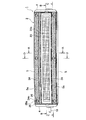
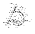
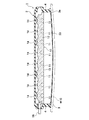
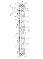
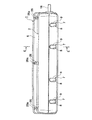
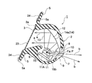
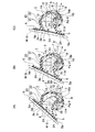
図1は本実施形態に係るターンシグナルランプの正面図、図2は図1のA−A線に沿う断面図、図3は図1のB−B線に沿う断面図、図4は図1のC−C線に沿う断面図、図5は図4の部分拡大図、図6は図1のD−D線に沿う断面図である。また、図7は本実施形態の背面図、図8は図7のE−E線に沿う断面図、図9はランプユニットの組付け姿勢の異なる形態を(A),(B),(C)にて示す図2と同様の断面図である。
1 is a front view of a turn signal lamp according to the present embodiment, FIG. 2 is a cross-sectional view taken along line AA in FIG. 1, FIG. 3 is a cross-sectional view taken along line BB in FIG. FIG. 5 is a partially enlarged view of FIG. 4, and FIG. 6 is a sectional view taken along the line DD of FIG. 1. 7 is a rear view of the present embodiment, FIG. 8 is a cross-sectional view taken along line EE in FIG. 7, and FIG. 9 is a view showing different forms of assembly of the lamp unit (A), (B), (
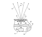
本実施形態のターンシグナルランプ1にあっては、図1,図2に示すように横長のハウジング2と、該ハウジング2内に配設されたランプユニット10、とを備えている。
The
ハウジング2は、弾性変形可能なゴム,軟質合成樹脂等の弾性材で構成され、正面に開口部3を有し、車幅方向端部が側壁4により閉塞された横長の略円筒形状に形成されている。
The
前記開口部3の上,下縁には、所要の前傾角度で取付フランジ5が外側に張り出して一体成形されている。
At the upper and lower edges of the
ランプユニット10は、光源11と、該光源11の出射光を導光して正面の発光面13よりハウジング2の開口部3方向に投光する導光体12と、を備えている。
The
導光体12は、その厚肉内を導光作用により前記光源11の光が直進可能な光の透過性の高い材料、例えば、アクリルやポリカーボネート等の合成樹脂材で構成されている。
The
この導光体12は、その正面の発光面13が略垂直の平担面に形成され、背面には導光体12内を直進した光源11の光を発光面13に向けて反射する反射面14が形成されている。
The
この反射面14は、導光体12の鉛直断面において、その下側部に焦点Faを持つ回転放物面を基調とする自由曲面に形成されていて、前記光源11は、その発光中心が前記反射面14の焦点Faの近傍となる位置に配設されている。
The reflecting
この光源11の出射光は、導光体12の導光作用により直進して前記反射面14に投光され、この光を反射面14の内面反射を利用して、該反射面14の回転放物面の水平基準軸0に対して平行光aとして発光面13に向けて反射するようになっている。
The light emitted from the
また、反射面14は導光体12の厚肉内にての光反射を行わせるため、外部への光透過防止と反射効率の向上を目的として、該反射面14の外面側に例えばアルミ蒸着等の表面処理層14aが施されている。
Further, since the reflecting
前記導光体12は、本実施形態にあっては、前記ハウジング2の車幅方向両端の側壁4,4の内面間に亘る長さで横長に形成されている。
In the present embodiment, the
一方、前記光源11として、LED等の半導体発光素子が用いられ、本実施形態では複数個、例えば、8個の光源11が導光体12の長さ方向(車幅方向)に適宜等間隔に配設されている。
On the other hand, a semiconductor light emitting element such as an LED is used as the
従って、前記回転放物面からなる反射面14は、図3に示すように各光源11に対応して、各光源11の発光中心を中心とする8個の反射面14が車幅方向に連続した形状に形成されている。
Therefore, as shown in FIG. 3, the reflecting
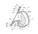
また、導光体12の下側部には、前記発光面13の下側に開放した凹欠部15が図4に示すように車幅方向に形成されている。
Further, a
前記8個の光源11は、車幅方向に長い1つの共通の基板11A上に固設され、該基板11Aを前記凹欠部15の下側に、該凹欠部15の下側開放部を閉塞するようにビス等により固設して、光源11が凹欠部15内において前記反射面14に対向するように配設されている(図2参照)。
The eight
この凹欠部15の前記光源11に対向する上側周面は凹球面状に形成されて、各光源11の出射光が導光体12内に効率良く導光光として取り込むことができるようにしている。
The upper peripheral surface of the
また、凹欠部15の車幅方向中央部位には、該凹欠部15を車幅方向に仕切る形で補強リブ15aが一体成形されている。
In addition, a reinforcing
そして、前記複数個の光源11と、導光体12とを備えたランプユニット10は、前記ハウジング2に上下方向に回動自在に軸支されている。
The
このランプユニット10の回動支持機構は、例えば、図4に示すように、導光体12の車幅方向両端面に突設した円形のボス部16と、ハウジング2の側壁4の内面に形成されて、前記ボス部16が嵌合する円形の軸受溝17と、によって構成することができる。
For example, as shown in FIG. 4, the rotation support mechanism of the
本実施形態にあっては、前記ランプユニット10の回動中心Pは、前記光源11の車幅方向延長上に設定されている。
In the present embodiment, the rotation center P of the
このため、ハウジング2の上,下壁は、ランプユニット10の回動中心Pを中心とする円弧状に形成されている。
For this reason, the upper and lower walls of the
また、このハウジング2の内面と、ランプユニット10の導光体12の外縁部との相互に、ランプユニット10の相対回動により係脱して該ランプユニット10の組付け姿勢を多段階に選択して固定可能なランプユニット固定手段20が設けられている。
Further, the assembly position of the
このランプユニット固定手段20は、例えば、図2に示すようにハウジング2の上壁内面に、開口部3の上縁から上壁と後壁との連設部分に亘って等間隔に設けられた複数個の係止溝21と、導光体12の上端縁に突設されて前記係止溝21と係脱する係止突起22と、で構成することができる。
For example, as shown in FIG. 2, the lamp unit fixing means 20 is provided on the inner surface of the upper wall of the
このランプユニット固定手段20は、ハウジング2の上壁内面および導光体12の上端縁に全体的に設ける必要はなく、例えば、それらの車幅方向中心の近傍に対称的に一対設けられる。
The lamp unit fixing means 20 does not need to be provided entirely on the inner surface of the upper wall of the
これにより、前記ランプユニット10は、図2に示す自動車のリヤウィンドウパネルW・Gの傾斜角度に応じて、ハウジング2に対して相対的に組付け姿勢が上下方向に回動調整可能とされている。
As a result, the
また、ハウジング2の開口部3の下縁側には、円弧形状の下壁との交点部分に、前記導光体12側に張り出して、先端が該導光体12の発光面13の下縁部に近接して前記凹欠部15および該凹欠部15内の光源11を隠蔽する遮蔽部6が突設されている。
Further, on the lower edge side of the
前記ハウジング2の開口部3の外側周縁には僅かな段差部3aが形成され、該段差部3aに薄板状のアウターレンズ23が接着固定されている。
A slight stepped
このアウターレンズ23は、着色透明または着色半透明の合成樹脂材で形成され、その外面には部分的に、例えば、図1に示すようにアウターレンズ23の上下方向中央部分に、光拡散面23aが車幅方向両端部近傍に亘って絞付け形成されている。
The
また、前記ハウジング2の背壁には、前記ランプユニット10の光源11の出射光の一部を車室前方に向けて透過させる光源作動確認用の投光窓部7が形成されている。
In addition, a light projecting window portion 7 for confirming the operation of the light source is formed on the back wall of the
この投光窓部7は、本実施形態にあっては、図4,図7に示すようにランプユニット10の車幅方向両端部の光源11と、それらからランプユニット中央側へ1つ置いた光源11に対応した計4ヶ所に設定されている。
In this embodiment, as shown in FIGS. 4 and 7, the light projecting window portion 7 is provided with
また、前述のようにランプユニット10とハウジング2とは、相対的に上下方向に回動して組付け姿勢を調整可能とされているため、前記投光窓部7は、ランプユニット10の組付け姿勢の回動調整によっても前記光源11と水平方向に対向可能なように縦長に形成されている。
Further, as described above, since the
更に、投光窓部7は、ハウジング2の背壁に形成された開窓部8と、該開窓部8に嵌合して接着固定されたキャップ9と、で構成されている。
Further, the light projecting window portion 7 includes an
キャップ9は、光の透過性の高い適宜の合成樹脂材で形成され、該キャップ9の光源11に対向する側は、例えば、図5に示すように球面状に形成して、光源11の光量を十分に取り込むプリズム機能を持たせてあり、この球面状部9aから取り込まれた入射光が、球面状部9aに続いて形成されたくびれ部9bにおける側壁反射作用と、キャップ表面出射時の屈折作用により、光の出射方向bを拡散制御するようになっている。
The
また、投光窓部7は、ハウジング2の背壁と円弧状の底壁とが断面くの字状に連設した部分に設けられているため、キャップ9は図8に示すように断面くの字状に形成されている。
Further, since the light projecting window portion 7 is provided at a portion where the back wall of the
一方、光源11は導光体12の下側部の凹欠部15に配設されていて、光源11の後方には凹欠部15の背壁が存在しているため、投光窓部7に対応する部分でこの背壁の光源11に対向する部位には、該光源11の光を投光窓部7に透過させるための開口15bが形成されている。
On the other hand, the
図1,図3中、符号18は光源11の基板11Aに接続される給電用のハーネスである。
1 and 3,
以上のように構成されたターンシグナルランプ1は、図2に示すように、ハウジング2の上,下の取付フランジ5,5により、例えば、両面接着テープ24を介して自動車のリヤウィンドウパネルW・Gの内面に、その傾斜に沿って接着固定される。
As shown in FIG. 2, the
このとき、ランプユニット10は、導光体12の発光面13が垂直となるように、予めその組付け姿勢が調整されてハウジング2に組付けられる。
At this time, the
前記両面接着テープ24の上下方向のずれ動きを阻止するため、前記取付フランジ5,5の取付面には、両面接着テープ24の厚み寸法よりも浅い溝5aが車幅方向に帯状に形成されている。
In order to prevent the double-sided
取付フランジ5,5の所要部位、例えば、本実施形態にあっては、その車幅方向中心部と車幅方向両端部とに、接着剤溜り25が凹設されていると共に、該接着剤溜り25と背面とを貫通して接着剤注入孔26と、該接着剤注入孔26よりも小径の接着剤充填確認孔26aとが併設されている一方、両面接着テープ24には、前記接着剤溜り25に対応する位置に、これと略同一径の貫通孔24aが形成されている(図1,図6参照)。
即ち、前記両面接着テープ24のみでは、リヤウィンドウパネルW・Gに対するターンシグナルランプ1の取付けが不十分な場合、前記接着剤注入孔26から前記接着剤溜り25に適宜の接着剤が注入充填され、両面接着テープ24の貫通孔24aを通してリヤウィンドウパネルW・Gと、取付フランジ5,5とが部分的に接着固定される。接着剤の充填量の適,不適は、前記充填確認孔26aからの接着剤の溢出によって容易に確認される。
That is, if the
以上の構成からなる本実施形態のターンシグナルランプ1にあっては、前記光源11の出射光は、導光体12の内部に導光されて、該導光体12の正面の発光面13からハウジング2の開口部3方向に投光され、リヤウィンドウパネルW・Gを通して車両後方に向けて照射される。
In the
前記導光体12は、その正面の発光面13が平坦に形成されて該発光面13を略垂直にして配設されている一方、該導光体12の背面には導光体12の下側部に焦点Faを持つ回転放物面からなる反射面14が形成され、前記焦点Faの近傍に光源11が配設されているため、この光源11の出射光を導光体12の導光作用により反射面14に効率良く直進,導光させて、該反射面14からその回転放物面の水平基準軸0に対して平行に発光面13に向けて略水平な平行光aとして投光させることができる。
The
このため、光源11の出射光の損失を抑えて光量の大きな所定パターンの信号光を、リヤウィンドウパネルW・G後方の所定の配光方向に照射させることができる。
For this reason, it is possible to irradiate a predetermined pattern of signal light having a large light amount in a predetermined light distribution direction behind the rear window panels W and G while suppressing loss of light emitted from the
特に、前記光源11は、導光体12の下側部の凹欠部15に配設されていて、該凹欠部15の光源11に対向する上側周面が凹球面状に形成されているため、光源11から出射される光束量を無駄なく導光体12内に取り込むことができると共に、導光体12内への入射時に光の屈折を殆んど無くして反射面14に投光させることができて、光量の増大を図ることができる。
In particular, the
そして、ランプユニット10は、ハウジング2に上下方向に回動自在に軸支されて、リヤウィンドウパネルW・Gの傾斜角度に応じて該ハウジング2に対して相対的に組付け姿勢を上下方向に回動調整可能とされている。従って、リヤウィンドウパネルW・Gの傾斜角度が図9の(A)に示すように小さい場合、または(C)に示すように傾斜角度が大きい場合、あるいは(B)に示すように傾斜角度が前記(A)と(C)の中間の角度の場合等に、予めハウジング2とランプユニット10との組付け姿勢をこれら(A)〜(C)に示すリヤウィンドウパネルW・Gの傾斜に応じて上下方向に回動調整し、導光体12の発光面13を常に垂直状態に維持させることで、前記リヤウィンドウパネルW・Gの傾斜角度の変化に追従して適正に取付けることができる。
The
このとき、光源11は基板11Aを介して導光体12の凹欠部15に固定配置され、光源11と導光体12の反射面14との位置関係が最適にセット固定されているため、前記組付け姿勢の回動調整によっても最も光量の無駄のない組付け姿勢が得られる。
At this time, the
しかも、ハウジング2の内面に設けた複数個の係止溝21と、導光体12の上端縁に突設した係止突起22と、から成るランプユニット固定手段20によって、前記ランプユニット10の組付け姿勢が多段階に選択して固定されるため、これら係止溝21と係止突起22との係脱により組付け姿勢の調整を容易に行えると共に、一旦、ハウジング2をリヤウィンドウパネルW・Gに装着した後は、ランプユニット10の組付け姿勢がその回動方向にずれ動くことがなく、品質感および信頼性を高めることができる。
Moreover, the
また、ハウジング2は、弾性変形可能なゴム,軟質合成樹脂等の弾性材で形成されているため、該ハウジング2の弾性変形によってランプユニット10の組付け姿勢の回動調整を容易に行うことができると共に、取付フランジ5の弾性によってリヤウィンドウパネルW・Gに無理なく装着することができる。また、この取付フランジ5がその弾性作用でリヤウィンドウパネルW・Gの湾曲面に馴染むため、ターンシグナルランプ1の異なる湾曲面位置にも追従して装着することができる。
Further, since the
そしてまた、ハウジング2の開口部3の下縁側に設けた遮蔽部6の先端が、導光体12の発光面13の下縁に近接して凹欠部15および該凹欠部15内の光源11を隠蔽しているため、光源11の出射光が開口部3に洩れ出るのを回避できると共に、外部から開口部3を通して光源11が見えるのを防止することができる。
Further, the front end of the shielding
更に、前記ランプユニット10は、光源11の車幅方向延長上でハウジング2に対して、ボス部16と軸受溝17とを介して回動自在とされているため、前記組付け姿勢の回動調整時に光源11の配設位置が前後方向にずれることがなく、どのような回動調整位置にあっても、所定の配光パターン,配光方向が変化するのを回避することができる。
Furthermore, since the
一方、前記光源11の出射光の一部は、導光体12の凹欠部15の背壁の開口15bを通過して、ハウジング2の背壁の投光窓部7から車室前方に向けて投光される。
On the other hand, a part of the light emitted from the
従って、運転者はこの投光窓部7を介して光源11の点灯状態を直接目視確認することができる。この結果、光源の断線を電気的に検知して、運転席近傍に設けられるインジケータ等の表示器により間接的に確認するものと比較して、誤作動に対する信頼性が高く、しかも、種々の電気部品を不要としてコスト的にも有利に得ることができる。
Therefore, the driver can directly visually check the lighting state of the
また、前記投光窓部7は縦長に形成されているため、前述のように図9の(A),(B),(C)に示すランプユニット10の組付け姿勢の各回動調整位置によっても、光源11の出射光の一部を投光窓部7を通して車室前方に向けて適正に投光させることができる。
Further, since the light projecting window portion 7 is formed in a vertically long shape, as described above, depending on each rotation adjustment position of the assembly posture of the
しかも、この投光窓部7は、ハウジング2の背壁に形成された開窓部8を、光透過性のキャップ9で覆った構成としてあるので、ハウジング2内に塵埃等が侵入するのを回避することができる。
Moreover, since the light projecting window portion 7 is configured such that the
なお、前記実施形態では本発明をターンシグナルランプを例に採って説明したが、ハイマウントストップランプに適用することも可能である。また、ハウジング2の開口部3に薄板状のアウターレンズ23を配設した例を開示したが、このアウターレンズ23を不要とすることもできる。更に、投光窓部7は複数個の光源11のうち、特定の光源11に対応して設けているが、全部の光源11に対応して設けてもよいことは勿論である。
In the above embodiment, the present invention has been described by taking a turn signal lamp as an example. However, the present invention can also be applied to a high-mount stop lamp. Moreover, although the example which arrange | positioned the thin plate-shaped
1 ターンシグナルランプ(車両用灯具)
2 ハウジング
3 開口部
7 投光窓部
8 開窓部
9 キャップ
10 ランプユニット
11 光源
12 導光体
13 発光面
14 反射面
1 Turn signal lamp (vehicle lamp)
2
Claims (4)
前記ハウジング内に配設され、光源および該光源の出射光を導光して正面の発光面よりハウジングの開口部方向に投光する導光体を有するランプユニットと、を備え、
前記ハウジングの背壁には、前記ランプユニットの光源の出射光の一部を車室前方に向けて透過させる光源作動確認用の投光窓部が形成されていることを特徴とする車両用灯具。 A housing having an opening on the front surface and fixed to the inner surface of the rear window panel of the vehicle via the periphery of the opening;
A lamp unit that is disposed in the housing and includes a light source and a light guide that guides light emitted from the light source and projects light from the front light emitting surface toward the opening of the housing, and
A vehicular lamp characterized in that a light projecting window portion for confirming the operation of a light source is formed on the back wall of the housing to transmit a part of the emitted light of the light source of the lamp unit toward the front of the passenger compartment. .
Priority Applications (1)
| Application Number | Priority Date | Filing Date | Title |
|---|---|---|---|
| JP2008173050A JP2010015744A (en) | 2008-07-02 | 2008-07-02 | Lighting fixture for vehicle |
Applications Claiming Priority (1)
| Application Number | Priority Date | Filing Date | Title |
|---|---|---|---|
| JP2008173050A JP2010015744A (en) | 2008-07-02 | 2008-07-02 | Lighting fixture for vehicle |
Publications (1)
| Publication Number | Publication Date |
|---|---|
| JP2010015744A true JP2010015744A (en) | 2010-01-21 |
Family
ID=41701688
Family Applications (1)
| Application Number | Title | Priority Date | Filing Date |
|---|---|---|---|
| JP2008173050A Pending JP2010015744A (en) | 2008-07-02 | 2008-07-02 | Lighting fixture for vehicle |
Country Status (1)
| Country | Link |
|---|---|
| JP (1) | JP2010015744A (en) |
Cited By (6)
| Publication number | Priority date | Publication date | Assignee | Title |
|---|---|---|---|---|
| EP2390137A1 (en) * | 2010-05-28 | 2011-11-30 | Hella KGaA Hueck & Co. | Illumination device for vehicles |
| JP2012089371A (en) * | 2010-10-20 | 2012-05-10 | Mitsuba Corp | Door mirror |
| JP2015024676A (en) * | 2013-07-24 | 2015-02-05 | アイシン精機株式会社 | Panel structure of sun roof |
| JP2015506572A (en) * | 2012-02-07 | 2015-03-02 | ダイムラー・アクチェンゲゼルシャフトDaimler AG | Car lighting equipment |
| JP2017209083A (en) * | 2016-05-27 | 2017-11-30 | イカリ消毒株式会社 | Insect-catching device |
| US20240210007A1 (en) * | 2022-12-26 | 2024-06-27 | Hyundai Mobis Co., Ltd. | Lamp |
-
2008
- 2008-07-02 JP JP2008173050A patent/JP2010015744A/en active Pending
Cited By (8)
| Publication number | Priority date | Publication date | Assignee | Title |
|---|---|---|---|---|
| EP2390137A1 (en) * | 2010-05-28 | 2011-11-30 | Hella KGaA Hueck & Co. | Illumination device for vehicles |
| JP2012089371A (en) * | 2010-10-20 | 2012-05-10 | Mitsuba Corp | Door mirror |
| JP2015506572A (en) * | 2012-02-07 | 2015-03-02 | ダイムラー・アクチェンゲゼルシャフトDaimler AG | Car lighting equipment |
| JP2015024676A (en) * | 2013-07-24 | 2015-02-05 | アイシン精機株式会社 | Panel structure of sun roof |
| JP2017209083A (en) * | 2016-05-27 | 2017-11-30 | イカリ消毒株式会社 | Insect-catching device |
| US20240210007A1 (en) * | 2022-12-26 | 2024-06-27 | Hyundai Mobis Co., Ltd. | Lamp |
| EP4394244A1 (en) * | 2022-12-26 | 2024-07-03 | Hyundai Mobis Co., Ltd. | Lamp comprinsing an inner lens |
| US12313238B2 (en) * | 2022-12-26 | 2025-05-27 | Hyundai Mobis Co., Ltd. | Lamp |
Similar Documents
| Publication | Publication Date | Title |
|---|---|---|
| JP5945238B2 (en) | Vehicle lamp and vehicle rear panel | |
| EP2353937B1 (en) | Vehicle lamp | |
| CN106195847B (en) | Mood light for vehicle | |
| JP6453999B2 (en) | Interior parts for vehicles | |
| CN109895688B (en) | Indirect lighting structure for vehicle roof | |
| US7220030B2 (en) | Exterior mirror having lamp and exterior rear-view mirror having lamp | |
| CN102963304A (en) | Vehicle door mirror | |
| JP2010015744A (en) | Lighting fixture for vehicle | |
| CN113682242A (en) | Decorative elements including backlight area | |
| CN113272178A (en) | Mirror device for vehicle and mirror display apparatus capable of irradiating light | |
| JP4700081B2 (en) | Vehicle lighting device | |
| JP6453998B2 (en) | Interior parts for vehicles | |
| JP2020113433A (en) | Rear combination lamp | |
| CN115703399A (en) | Lighting device for use in vehicle | |
| JP2014094656A (en) | Decorative illumination device | |
| US20230398929A1 (en) | Vehicle sun visor | |
| JP6357887B2 (en) | Vehicle lamp, vehicle outside mirror device | |
| JP5329872B2 (en) | Vehicle lamp and door mirror with built-in vehicle lamp | |
| JP2010015743A (en) | Lighting fixture for vehicle | |
| JP2014172440A (en) | Light body for vehicle and door mirror with light body | |
| CN111741874A (en) | lighting device | |
| JP2010052444A (en) | Vehicular lamp and door mirror incorporating the vehicular lamp | |
| JP4768062B2 (en) | Automotive interior lighting equipment | |
| JP7542392B2 (en) | Vehicle Warning Device | |
| JP7493426B2 (en) | Vehicle Warning Device |