EP4394135A1 - Work machine - Google Patents
Work machine Download PDFInfo
- Publication number
- EP4394135A1 EP4394135A1 EP23206559.9A EP23206559A EP4394135A1 EP 4394135 A1 EP4394135 A1 EP 4394135A1 EP 23206559 A EP23206559 A EP 23206559A EP 4394135 A1 EP4394135 A1 EP 4394135A1
- Authority
- EP
- European Patent Office
- Prior art keywords
- footplate
- cabin
- sealing material
- mounting portion
- outer edge
- Prior art date
- Legal status (The legal status is an assumption and is not a legal conclusion. Google has not performed a legal analysis and makes no representation as to the accuracy of the status listed.)
- Pending
Links
Images




Classifications
-
- E—FIXED CONSTRUCTIONS
- E02—HYDRAULIC ENGINEERING; FOUNDATIONS; SOIL SHIFTING
- E02F—DREDGING; SOIL-SHIFTING
- E02F9/00—Component parts of dredgers or soil-shifting machines, not restricted to one of the kinds covered by groups E02F3/00 - E02F7/00
- E02F9/16—Cabins, platforms, or the like, for drivers
-
- B—PERFORMING OPERATIONS; TRANSPORTING
- B62—LAND VEHICLES FOR TRAVELLING OTHERWISE THAN ON RAILS
- B62D—MOTOR VEHICLES; TRAILERS
- B62D33/00—Superstructures for load-carrying vehicles
- B62D33/06—Drivers' cabs
- B62D33/0604—Cabs insulated against vibrations or noise, e.g. with elastic suspension
-
- B—PERFORMING OPERATIONS; TRANSPORTING
- B62—LAND VEHICLES FOR TRAVELLING OTHERWISE THAN ON RAILS
- B62D—MOTOR VEHICLES; TRAILERS
- B62D33/00—Superstructures for load-carrying vehicles
- B62D33/06—Drivers' cabs
- B62D33/0617—Drivers' cabs for tractors or off-the-road vehicles
Definitions
- the present invention relates to, for example, a work machine such as an excavator.
- Patent Literature 1 a work machine which outputs an alarming sound in association with the traveling of the work machine.
- An operator of such a work machine is exposed to various noises generated due to work, as well as the alarming sound.
- the cabin shuts out the sounds. This can reduce the noises that reach the operator.
- Such an opening 30 faces the space 31 communicating with the inside of the cabin 5 and thus serves as a path that lets an outside noise pass therethrough. This causes the outside noise to enter the cabin 5 through the opening 30.
- Fig. 8 illustrates a state where any measure has not yet been carried out on the opening 30.
Landscapes
- Engineering & Computer Science (AREA)
- Mining & Mineral Resources (AREA)
- Civil Engineering (AREA)
- General Engineering & Computer Science (AREA)
- Structural Engineering (AREA)
- Chemical & Material Sciences (AREA)
- Combustion & Propulsion (AREA)
- Transportation (AREA)
- Mechanical Engineering (AREA)
- Component Parts Of Construction Machinery (AREA)
- Body Structure For Vehicles (AREA)
Abstract
Description
- The present invention relates to, for example, a work machine such as an excavator.
- Conventionally, a work machine has been known which outputs an alarming sound in association with the traveling of the work machine (for example, Patent Literature 1). An operator of such a work machine is exposed to various noises generated due to work, as well as the alarming sound. In a case of a work machine which is provided with a cabin for covering an operator seat, the cabin shuts out the sounds. This can reduce the noises that reach the operator.
- The cabin is mounted on an upper surface of a footplate which is a floor of the operator seat with use of bolts or the like. A peripheral wall of the cabin has a bottom portion provided with a mounting portion having a frame shape extending toward an inner side of the cabin. The cabin is fixed to the footplate by screwing the mounting portion of the cabin to an outer edge portion of the footplate in a state where the mounting portion is in contact with the outer edge portion. Both the mounting portion and the footplate are sheet metals. Thus, the screwing brings the sheet metals into close contact with each other, thereby sealing a contact portion between the sheet metals. A gap at the contact portion between the sheet metals is set to zero as a standard dimension.
- [Patent Literature 1]
Japanese Patent Application Publication, Tokukaihei, No. 6-17450 - However, even when such a gap is set to zero as a standard dimension, actually, a gap occurs at the contact portion. This gap occurs due to bending of the footplate caused by, for example, weights of installation components, such as an operator seat installed on the footplate and a weight of the operator seated on the operator seat. The gap occurring at the contact portion lets an outside noise enter the cabin through the gap and thus causes an increase in a noise near the ears of the operator.
- An aspect of the present invention is achieved in light of the foregoing problem. It is an object of the aspect of the present invention to provide a work machine which makes an outside noise less likely to enter a cabin of the work machine.
- In order to solve the foregoing problem, a work machine in accordance with an aspect of the present invention includes: a machine body; a footplate installed on the machine body; and a cabin installed on the footplate, wherein the cabin has, at a bottom portion of a peripheral wall of the cabin, a mounting portion extending toward an inner side of the cabin and is fixed to the footplate by screwing the mounting portion to an outer edge portion of the footplate at screwed portions in a state where the mounting portion is in contact with the outer edge portion, and a sealing material is disposed between the mounting portion and the outer edge portion in a state where the sealing material elastically deforms.
- An aspect of the present invention makes it possible to achieve a work machine which makes an outside noise less likely to enter a cabin of the work machine.
-
-
Fig. 1 is a perspective view schematically illustrating an entire configuration of a work machine in accordance with an embodiment of the present invention. -
Fig. 2 is a perspective view schematically illustrating an interior of a cabin of the work machine. -
Fig. 3 is a perspective view schematically illustrating the cabin and a footplate in a separated state. -
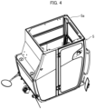
Fig. 4 is a perspective view schematically illustrating the cabin with a bottom surface side thereof facing upward. -
Fig. 5 is a partially exploded perspective view and a partially enlarged view which illustrate a structure in which the sealing material is mounted to the footplate. -
Fig. 6 is a cross-sectional perspective view illustrating a main part of a portion at which the cabin is mounted on the footplate. -
Fig. 7 is an enlarged view of an area A illustrated inFig. 1 . -
Fig. 8 is a cross-sectional perspective view of a main part that indicates a position of an opening communicating with an outside of the cabin. -
Fig. 9 is a cross-sectional perspective view illustrating the work machine cut along a horizontal plane. -
Fig. 10 is an enlarged view of an area B illustrated inFig. 9 . -
Fig. 11 is a view illustrating a state in which an expandable sheet that has not yet been expanded is disposed in the opening. - The following will describe an embodiment of the present invention with reference to drawings as appropriate.
-
Fig. 1 is a perspective view schematically illustrating an entire configuration of a work machine 1 in accordance with the present embodiment.Fig. 2 is a perspective view schematically illustrating an interior of acabin 5 of the work machine 1. In the present embodiment, an excavator is taken as an example of the work machine 1. - As illustrated in
Fig. 1 , the work machine 1 includes atraveling device 2, amachine body 3, and awork device 4. Themachine body 3 is supported on a frame of the travelingdevice 2 with a bearing member interposed between themachine body 3 and the frame, so as to be able to swivel about a vertical axis (an axis in an up-and-down direction). Installed in themachine body 3 are acabin 5, an engine 6, ahood 7, acounterweight 8, thework device 4, and the like. - As illustrated in
Fig. 2 , an operator seat 20 (installation component) on which an operator (driver) is to be seated is provided in an interior of the cabin 5 (hereinafter, also referred to as "room"). Theoperator seat 20 is installed on afootplate 21 which is a floor in the room. Disposed around theoperator seat 20 are, although not illustrated, a plurality of electronic components (such as a display device and an air conditioner), in addition to thetraveling device 2, thework device 4, and a plurality of operation levers 22 for operating themachine body 3. The following description will assume that a front side of the operator seated on theoperator seat 20 is the front, a rear side of the operator is the rear, a left side of the operator is the left, and a right side of the operator is the right. Thecabin 5 is installed on themachine body 3 so as to be close to a left side of themachine body 3. - As illustrated in
Fig. 1 , thework device 4 is operated with use of working hydraulic pressures as working fluid pressures and is installed in a front portion of themachine body 3. Thework device 4 includes, for example, afirst boom 15 rotationally moved by ahydraulic cylinder 11, asecond boom 16 rotationally moved byhydraulic cylinders arm 17 rotationally moved by ahydraulic cylinder 13, and abucket 18 rotationally moved by ahydraulic cylinder 14. -
Fig. 3 is a perspective view schematically illustrating thecabin 5 and thefootplate 21 in a separated state.Fig. 4 is a perspective view schematically illustrating thecabin 5 with a bottom surface side thereof facing upward. - As illustrated in
Fig. 3 , thecabin 5 is fixed onto the above-describedfootplate 21 on which theoperator seat 20 is installed. As illustrated inFig. 4 , a peripheral wall of thecabin 5 has a bottom portion on which amounting portion 5a is provided so as to extend toward an inner side of thecabin 5. Themounting portion 5a has a frame shape. Thecabin 5 is fixed to thefootplate 21 by screwing themounting portion 5a of thecabin 5 to anouter edge portion 21a of thefootplate 21 at screwed portions with use bolts or the like in a state where themounting portion 5a is in contact with theouter edge portion 21a. - Both the
mounting portion 5a and thefootplate 21 are sheet metals. Thus, in a conventional configuration that does not include a sealing material 25 (described later), the screwing brings the plate metals into close contact with each other, thereby sealing a contact portion between the plate metals. However, as described above, in such a configuration, bending of thefootplate 21 is caused by weights of installation components such as theoperator seat 20 and a weight of an operator or the like seated on theoperator seat 20. Therefore, a gap occurs at a contact portion between theouter edge portion 21a of thefootplate 21 and themounting portion 5a of thecabin 5. - In order to address such a problem, the work machine 1 is provided with the sealing
material 25 which is, as illustrated inFig. 3 , disposed between the mountingportion 5a and theouter edge portion 21a in a state where the sealingmaterial 25 elastically deforms. The sealingmaterial 25 elastically deforms in a state where thecabin 5 is mounted on (screwed to) thefootplate 21. The sealingmaterial 25 has an elongated shape extending along an outer edge of thefootplate 21 and is made of an elastic material such as rubber. Examples of the sealingmaterial 25 include a rubber sponge. - Even when a gap occurs due to the bending of the
footplate 21, the sealingmaterial 25 which is disposed, as described above, between the mountingportion 5a and theouter edge portion 21a in a state of being elastically deformed by a weight of thecabin 5 mounted on thefootplate 21 can restore its original shape and fill the gap. This makes it possible to prevent an outside noise from entering thecabin 5 through the gap caused by the bending of thefootplate 21. - More specifically, such a gap due to the bending of the
footplate 21 occurs in a location between the screwed portions adjacent to each other. Thus, in the present embodiment, the sealingmaterial 25 is disposed in a location between the screwed portions and between the mountingportion 5a and theouter edge portion 21a. Note that, althoughFig. 3 illustrates, as an example, a configuration in which the sealingmaterial 25 is disposed on thefootplate 21, an alternative configuration may be employed in which the sealingmaterial 25 is disposed on the mountingportion 5a of thecabin 5. As such, the sealingmaterial 25 is disposed only in a location in which a gap may occur. This can prevent waste of the sealingmaterial 25. - In the present embodiment, the
footplate 21 has a substantially quadrangular shape, and the mountingportion 5a is screwed to the footplate 21 at four corners of thefootplate 21. Therefore, the sealingmaterial 25 is disposed at each of end portions of four sides of the footplate 21 except for the four corners. In such a configuration in which the mountingportion 5a is screwed to the footplate 21 at the four corners of thefootplate 21, disposing the sealingmaterial 25 at each of the end portions except for the four corners makes it possible to efficiently fill gaps in four directions caused by the bending of thefootplate 21. -
Fig. 5 is a partially exploded perspective view and a partially enlarged view which illustrate a structure in which the sealingmaterial 25 is mounted to thefootplate 21.Fig. 6 is a cross-sectional perspective view illustrating a main part of a portion at which thecabin 5 is mounted on thefootplate 21. - As illustrated in
Figs. 5 and6 , in the present embodiment, theouter edge portion 21a has, in a location between the screwed portions, astep portion 24 forming a level difference in a direction away from the mountingportion 5a. The sealingmaterial 25 is disposed in thestep portion 24. Note that, althoughFigs. 5 and6 illustrate, as an example, a configuration in which thestep portion 24 is provided to thefootplate 21 on which the sealingmaterial 25 is disposed, an alternative configuration may be employed in which thestep portion 24 is provided to the mountingportion 5a of thecabin 5, and the sealingmaterial 25 is disposed on the mountingportion 5a. That is, it is necessary only that one of the mountingportion 5a and theouter edge portion 21a has, in the location between the screwed portions, thestep portion 24 forming a level difference in a direction away from the other one of the mountingportion 5a and theouter edge portion 21a, and the sealingmaterial 25 is disposed in thecorresponding step portion 24. - In this way, the
step portion 24 is provided such that the level of an upper surface of the footplate 21 in a location where the sealingmaterial 25 is disposed is lower than the level of the upper surface of the footplate 21 in a location where the sealingmaterial 25 is not disposed (or the level of a lower surface of the mountingportion 5a in a location where the sealingmaterial 25 is disposed is higher than the level of the lower surface of the mountingportion 5a in a location where the sealingmaterial 25 is not disposed). This allows the sealingmaterial 25 to be thick and thus provides an adequate amount by which the sealingmaterial 25 is crushed. Thus, even when a change in an amount by which thefootplate 21 bends occurs due to, for example, a difference in weight among operators and results in a change in size of the gap, the sealingmaterial 25 changes its shape and size with the change in size of the gap and fills the gap. In addition, thethick sealing material 25 can maintain its elasticity for a longer period of time than athin sealing material 25 can and thus can secure sealing properties for a longer period of time. - As illustrated in
Fig. 5 , thestep portion 24 provided at theouter edge portion 21a is formed by: forming anotch portion 21b at theouter edge portion 21a so as to extend along the outer edge of thefootplate 21; and fixing asupport plate 23 to the lower surface of the footplate 21 in such a manner that thesupport plate 23 covers thenotch portion 21b from a lower surface side of thefootplate 21. In other words, thestep portion 24 includes: thenotch portion 21b extending along the outer edge and thesupport plate 23 that is fixed to the lower surface of thefootplate 21 and that cover thenotch part 21b from the lower surface side of thefootplate 21. Thesupport plate 23 is an elongated plate-metal member having an enough size to cover thenotch part 21b. Thesupport plate 23 is fixed to the lower surface of the footplate 21 by, for example, welding. - Such a configuration makes it possible to easily achieve the
step portion 24 for securing the thickness of the sealingmaterial 25. Note that a similar configuration can be employed in a case where thestep portion 24 is provided to the mountingportion 5a. - Although not illustrated, the sealing
material 25 is disposed on an upper surface of thesupport plate 23. In a state where thecabin 5 has not yet been mounted on thefootplate 21, the upper surface of the sealingmaterial 25 protrudes upward from the upper surface of the footplate 21 through thenotch portion 21b. This protruding part corresponds to the amount by which the sealingmaterial 25 is crushed when thecabin 5 is mounted. - As illustrated in
Fig. 6 , when the mountingportion 5a of thecabin 5 is mounted on theouter edge portion 21a of thefootplate 21, the sealingmaterial 25 is pressed by the mountingportion 5a and accordingly elastically deforms. In a state where the sealingmaterial 25 elastically deforms, the upper surface of the sealingmaterial 25 is flush with the upper surface of thefootplate 21. This results in a state where no gap is present at a contact portion between theouter edge portion 21a and the mountingportion 5a similarly as at the screwed portions. The sealingmaterial 25 always applies, to the mountingportion 5a, a force in an upward direction with use of the restoring force of the sealingmaterial 25. - The sealing
material 25 may be an independent member separate from the footplate 21 or the mountingportion 5a. Alternatively, the sealingmaterial 25 may be, for example, bonded to or fitted into the footplate 21 or the mountingportion 5a in advance to be difficult to detach from the footplate 21 or the mountingportion 5a. This can eliminate the need for positioning the sealingmaterial 25 relative to the footplate 21 or the mountingportion 5a in a step of installing thecabin 5 on thefootplate 21. Thus, the workability is improved. - The work machine 1 has another path that lets an outside noise enter the
cabin 5 as well as the gap caused by the bending of thefootplate 21. It is preferable to also fill such a path. -
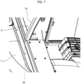
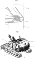
Fig. 7 is an enlarged view of an area A illustrated inFig. 1 .Fig. 8 is a cross-sectional perspective view illustrating a main part that indicates a position of anopening 30 communicating with an outside of thecabin 5.Fig. 9 is a cross-sectional perspective view illustrating the work machine 1 cut along a horizontal plane.Fig. 10 is an enlarged view of an area B illustrated inFig. 9 . - The
cabin 5 is formed by welding combined plate metals which are processed into predetermined shapes such as a curved shape. Thus, in some cases, an opening (gap) that cannot be completely filled occurs, for example, between the plate metals. In other cases, an opening is provided for a reason concerning a production process. As an example of such an opening, as illustrated inFigs. 7 and8 , a relativelylarge opening 30 communicating with the outside of thecabin 5 is present on a lower side of aframe 5c on a right side of a rear portion of thecabin 5. - This
opening 30 inevitably occurs when aspace 31 is provided at the right-side portion of the rear portion of thecabin 5 at which theframe 5c is located. Thespace 31 is a space through which a harness for wiring arrangement around a ceiling of thecabin 5 passes. Theopening 30 communicates with the inside and the outside of thecabin 5. Thespace 31 is a space communicating with the inside of thecabin 5. In thespace 31, a harness for a front light and a rear light which are mounted to an upper portion of thecabin 5 is installed. - Such an
opening 30 faces thespace 31 communicating with the inside of thecabin 5 and thus serves as a path that lets an outside noise pass therethrough. This causes the outside noise to enter thecabin 5 through theopening 30.Fig. 8 illustrates a state where any measure has not yet been carried out on theopening 30. -
Fig. 9 is a cross-sectional perspective view illustrating the work machine 1 cut along a horizontal plane.Fig. 10 is an enlarged view of an area B illustrated inFig. 9. Figs. 9 and10 each illustrate a state where a measure has been carried out on theopening 30. In order to prevent a noise from entering thecabin 5 through theopening 30, the work machine 1 has anexpandable member 32, disposed in theopening 30, for filling theopening 30, as illustrated inFigs. 9 and10 . The disposition of theexpandable member 32 fills theopening 30. This makes it possible to prevent an outside noise from entering thecabin 5 from theopening 30 through thespace 31. - In such a configuration of filling the
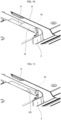
opening 30 with use of theexpandable member 32, theexpandable member 32 can be expanded by utilizing heat generated in a step of drying a coating applied to thecabin 5. That is, as illustrated inFig. 11 , anexpandable sheet 32S cut into the shape of theopening 30 is disposed in theopening 30 in advance before the step of drying a coating of thecabin 5. Theexpandable sheet 32S is then expanded to fill theopening 30, by utilizing heat generated in the step of drying the coating applied to thecabin 5.Fig. 11 is a view illustrating a state in which theexpandable sheet 32S that has not yet been expanded is disposed in theopening 30. - Note that, here, the
opening 30 that faces thespace 31 through which the harness for wiring arrangement around the ceiling passes is taken as an example of an opening which can be a path that lets a noise enter thecabin 5. However, there is no limitation on such an opening. That is, any opening (gap) which can structurally be a path that lets a noise enter thecabin 5 can be filled by utilizing heat generated in a step of drying the coating applied to thecabin 5, by disposing theexpandable sheet 32S cut into the shape of the opening (gap), in the opening (gap) in advance. - Aspects of the present invention can also be expressed as follows:
A work machine in accordance with an aspect of the present invention includes: a machine body; a footplate installed on the machine body; and a cabin installed on the footplate, wherein the cabin has, at a bottom portion of a peripheral wall of the cabin, a mounting portion extending toward an inner side of the cabin and is fixed to the footplate by screwing the mounting portion to an outer edge portion of the footplate at screwed portions in a state where the mounting portion is in contact with the outer edge portion, and a sealing material is disposed between the mounting portion and the outer edge portion in a state where the sealing material elastically deforms. - According to the above configuration, even when a gap occurs due to bending of the footplate, the sealing material can fill the gap by being restored to its original shape. This makes it possible to prevent an outside noise from entering the cabin through the gap caused by the bending of the footplate.
- A work machine in accordance with an aspect of the present invention may be configured such that the sealing material is provided between the mounting portion and the outer edge portion and is disposed in a location between the screwed portions.
- According to the above configuration, the sealing material is disposed only in a location in which a gap may occur. This makes it possible to prevent waste of the sealing material.
- A work machine in accordance with an aspect of the present invention may be configured such that one of the mounting portion and the outer edge portion has, in the location between the screwed portions, a step portion forming a level difference in a direction away from the other one of the mounting portion and the outer edge portion, and the sealing material is disposed in the step portion.
- According to the above configuration, it is possible to allow the sealing material to be thick and thus provides an adequate amount by which the sealing material is crushed. Thus, even when the gap changes in size due to a change in amount of bending of the footplate, the sealing material changes its shape and size with the change in size of the gap, and fills the gap.
- A work machine in accordance with an aspect of the present invention may be configured such that the step portion is provided in the outer edge portion, and the step portion includes: a notch portion extending along an outer edge of the footplate; and a support plate being fixed to a lower surface of the footplate and covering the notch portion from a lower surface side of the footplate. According to the above configuration, it is possible to easily achieve the step portions.
- A work machine in accordance with an aspect of the present invention may be configured such that the footplate has a substantially quadrangular shape, the mounting portion is screwed to the footplate at four corners of the footplate, and the sealing material is disposed at each of end portions of the footplate except for the four corners.
- According to the above configuration, in a configuration in which the mounting portion is screwed to the footplate at the four corners of the footplate, it is possible to fill gaps in four directions caused by the bending of the footplate.
- A work machine in accordance with an aspect of the present invention may be configured such that, in an opening that faces a space communicating with an inside of the cabin, an expandable member for filling the opening is disposed.
- According to the above configuration, it is possible to prevent an outside noise from entering the cabin from the opening through the space.
- A work machine in accordance with an aspect of the present invention may be configured such that the space is a space for allowing a harness for an electronic component to pass therethrough.
- According to the above configuration, it is possible to prevent an outside noise from entering the cabin from the opening for drawing the harness to the outside.
- The present invention is not limited to the embodiments, but can be altered by a skilled person in the art within the scope of the claims. The present invention also encompasses, in its technical scope, any embodiment derived by combining technical means disclosed in differing embodiments.
-
- 1
- Work machine
- 3
- Machine body
- 4
- Work device
- 5
- Cabin
- 5a
- Mounting portion
- 20
- Operator seat
- 21
- Footplate
- 21a
- Outer edge portion
- 23
- Support plate
- 24
- Step portion
- 25
- Sealing material
- 30
- Opening
- 31
- Space
- 32
- Expandable member
Claims (7)
- A work machine (1) comprising:a machine body (3);a footplate (21) installed on the machine body; anda cabin (5) installed on the footplate,wherein the cabin has, at a bottom portion of a peripheral wall of the cabin, a mounting portion (5a) extending toward an inner side of the cabin and is fixed to the footplate (21) by screwing the mounting portion to an outer edge portion (21a) of the footplate at screwed portions in a state where the mounting portion is in contact with the outer edge portion, anda sealing material (25) is disposed between the mounting portion (5a) and the outer edge portion (21a) in a state where the sealing material elastically deforms.
- The work machine according to claim 1, wherein the sealing material (25) is provided between the mounting portion (5a) and the outer edge portion (21a) and is disposed in a location between the screwed portions.
- The work machine according to claim 2, wherein:one of the mounting portion (5a) and the outer edge portion (21a) has, in the location between the screwed portions, a step portion (24) forming a level difference in a direction away from the other one of the mounting portion and the outer edge portion; andthe sealing material (25) is disposed in the step portion.
- The work machine according to claim 3, wherein:the step portion (24) is provided in the outer edge portion (21a); andthe step portion includes:a notch portion (21b) extending along an outer edge of the footplate; anda support plate (23) being fixed to a lower surface of the footplate and covering the notch portion from a lower surface side of the footplate.
- The work machine according to any one of claims 1 to 4, wherein:the footplate (21) has a substantially quadrangular shape;the mounting portion (5a) is screwed to the footplate at four corners of the footplate; andthe sealing material (25) is disposed at each of end portions of the footplate except for the four corners.
- The work machine according to any one of claims 1 to 5, wherein, in an opening (30) that faces a space (31) communicating with an inside of the cabin (5), an expandable member (32) for filling the opening is disposed.
- The work machine according to claim 6, wherein the space (31) is a space for allowing a harness for an electronic component to pass therethrough.
Applications Claiming Priority (1)
| Application Number | Priority Date | Filing Date | Title |
|---|---|---|---|
| JP2022208881A JP7811901B2 (en) | 2022-12-26 | 2022-12-26 | Work equipment |
Publications (1)
| Publication Number | Publication Date |
|---|---|
| EP4394135A1 true EP4394135A1 (en) | 2024-07-03 |
Family
ID=88600591
Family Applications (1)
| Application Number | Title | Priority Date | Filing Date |
|---|---|---|---|
| EP23206559.9A Pending EP4394135A1 (en) | 2022-12-26 | 2023-10-27 | Work machine |
Country Status (3)
| Country | Link |
|---|---|
| US (1) | US20240209594A1 (en) |
| EP (1) | EP4394135A1 (en) |
| JP (1) | JP7811901B2 (en) |
Citations (8)
| Publication number | Priority date | Publication date | Assignee | Title |
|---|---|---|---|---|
| JPS50134901U (en) * | 1974-04-20 | 1975-11-06 | ||
| GB2024113A (en) * | 1978-06-23 | 1980-01-09 | Kubota Ltd | Mounting of a tilt cabin in a working vehicle |
| JPS60177348U (en) * | 1984-05-04 | 1985-11-25 | 新キャタピラ−三菱株式会社 | Cab vibration isolator |
| JPH0617450A (en) | 1992-07-01 | 1994-01-25 | Kubota Corp | Travel control device for work equipment |
| JPH06136787A (en) * | 1992-10-22 | 1994-05-17 | Hitachi Constr Mach Co Ltd | Working machine with cab |
| CN202755392U (en) * | 2012-07-02 | 2013-02-27 | 广西柳工机械股份有限公司 | Loader cab |
| US10611413B2 (en) * | 2016-09-29 | 2020-04-07 | Hitachi Construction Machinery Co., Ltd. | Construction machine |
| CN111851619A (en) * | 2020-07-02 | 2020-10-30 | 中联重科股份有限公司 | bulldozer |
Family Cites Families (5)
| Publication number | Priority date | Publication date | Assignee | Title |
|---|---|---|---|---|
| US5286081A (en) * | 1993-01-21 | 1994-02-15 | Martin Sheet Metal, Inc. | Panel cab |
| JP2001081811A (en) * | 1999-09-14 | 2001-03-27 | Komatsu Ltd | Cab for construction machinery |
| JP5562763B2 (en) * | 2009-08-27 | 2014-07-30 | 日立建機株式会社 | Construction machinery |
| JP7105645B2 (en) * | 2018-07-31 | 2022-07-25 | 株式会社小松製作所 | cabs and work machines |
| JP2022001478A (en) * | 2020-06-22 | 2022-01-06 | 株式会社ブリヂストン | Cab mount |
-
2022
- 2022-12-26 JP JP2022208881A patent/JP7811901B2/en active Active
-
2023
- 2023-10-27 EP EP23206559.9A patent/EP4394135A1/en active Pending
- 2023-10-31 US US18/385,429 patent/US20240209594A1/en active Pending
Patent Citations (8)
| Publication number | Priority date | Publication date | Assignee | Title |
|---|---|---|---|---|
| JPS50134901U (en) * | 1974-04-20 | 1975-11-06 | ||
| GB2024113A (en) * | 1978-06-23 | 1980-01-09 | Kubota Ltd | Mounting of a tilt cabin in a working vehicle |
| JPS60177348U (en) * | 1984-05-04 | 1985-11-25 | 新キャタピラ−三菱株式会社 | Cab vibration isolator |
| JPH0617450A (en) | 1992-07-01 | 1994-01-25 | Kubota Corp | Travel control device for work equipment |
| JPH06136787A (en) * | 1992-10-22 | 1994-05-17 | Hitachi Constr Mach Co Ltd | Working machine with cab |
| CN202755392U (en) * | 2012-07-02 | 2013-02-27 | 广西柳工机械股份有限公司 | Loader cab |
| US10611413B2 (en) * | 2016-09-29 | 2020-04-07 | Hitachi Construction Machinery Co., Ltd. | Construction machine |
| CN111851619A (en) * | 2020-07-02 | 2020-10-30 | 中联重科股份有限公司 | bulldozer |
Also Published As
| Publication number | Publication date |
|---|---|
| JP2024092745A (en) | 2024-07-08 |
| US20240209594A1 (en) | 2024-06-27 |
| JP7811901B2 (en) | 2026-02-06 |
Similar Documents
| Publication | Publication Date | Title |
|---|---|---|
| US9441344B2 (en) | Controller assembly, cab for work machine, and work machine | |
| JP4996742B2 (en) | Work machine cab stopper device and method of assembling the same, and work machine cab | |
| JP5624690B1 (en) | Cab and work vehicle | |
| US8646557B2 (en) | Construction machine | |
| EP4124185A1 (en) | Waterproof structure for communication apparatus, communication unit, and work machine | |
| US20240209594A1 (en) | Work machine | |
| EP1138835A1 (en) | Compact hydraulic excavator | |
| JP6804881B2 (en) | Resin fuel tank mounting structure and construction machinery | |
| KR101778827B1 (en) | Construction machinery | |
| JP2002172979A (en) | Vehicle console box mounting structure | |
| JP6922960B2 (en) | Construction machinery | |
| JP6988241B2 (en) | Construction machinery | |
| WO2016063395A1 (en) | Controller assembly and work machine cab | |
| CN104334804B (en) | construction machinery | |
| JP2011148471A (en) | Cabin of working vehicle | |
| JP5541448B2 (en) | Construction vehicle | |
| JP2002061227A (en) | Bulldozer floor frame and bulldozer ROPS cab provided with the floor frame | |
| JP5780047B2 (en) | Construction machinery piping structure | |
| KR20050060007A (en) | Cap for construction machinery | |
| JP4236550B2 (en) | Tank mounting structure for swivel work machine | |
| JP4101849B2 (en) | Swivel work machine | |
| CN100471729C (en) | Unit Mounting Construction | |
| JP2017031759A (en) | Waterproof device | |
| JP7613233B2 (en) | Construction machinery operator's floor structure | |
| JP2025109587A (en) | Vehicle underbody structure |
Legal Events
| Date | Code | Title | Description |
|---|---|---|---|
| PUAI | Public reference made under article 153(3) epc to a published international application that has entered the european phase |
Free format text: ORIGINAL CODE: 0009012 |
|
| STAA | Information on the status of an ep patent application or granted ep patent |
Free format text: STATUS: REQUEST FOR EXAMINATION WAS MADE |
|
| 17P | Request for examination filed |
Effective date: 20231027 |
|
| AK | Designated contracting states |
Kind code of ref document: A1 Designated state(s): AL AT BE BG CH CY CZ DE DK EE ES FI FR GB GR HR HU IE IS IT LI LT LU LV MC ME MK MT NL NO PL PT RO RS SE SI SK SM TR |
|
| GRAP | Despatch of communication of intention to grant a patent |
Free format text: ORIGINAL CODE: EPIDOSNIGR1 |
|
| STAA | Information on the status of an ep patent application or granted ep patent |
Free format text: STATUS: GRANT OF PATENT IS INTENDED |
|
| INTG | Intention to grant announced |
Effective date: 20260317 |
|
| RIN1 | Information on inventor provided before grant (corrected) |
Inventor name: SATO, KEN Inventor name: HAYASHI, YOSUKE |