EP4393830A1 - Drug supply device - Google Patents
Drug supply device Download PDFInfo
- Publication number
- EP4393830A1 EP4393830A1 EP22875996.5A EP22875996A EP4393830A1 EP 4393830 A1 EP4393830 A1 EP 4393830A1 EP 22875996 A EP22875996 A EP 22875996A EP 4393830 A1 EP4393830 A1 EP 4393830A1
- Authority
- EP
- European Patent Office
- Prior art keywords
- packaging paper
- drug
- drug packaging
- upstream
- paper
- Prior art date
- Legal status (The legal status is an assumption and is not a legal conclusion. Google has not performed a legal analysis and makes no representation as to the accuracy of the status listed.)
- Granted
Links
Images




Classifications
-
- B—PERFORMING OPERATIONS; TRANSPORTING
- B65—CONVEYING; PACKING; STORING; HANDLING THIN OR FILAMENTARY MATERIAL
- B65B—MACHINES, APPARATUS OR DEVICES FOR, OR METHODS OF, PACKAGING ARTICLES OR MATERIALS; UNPACKING
- B65B9/00—Enclosing successive articles, or quantities of material, e.g. liquids or semiliquids, in flat, folded, or tubular webs of flexible sheet material; Subdividing filled flexible tubes to form packages
- B65B9/06—Enclosing successive articles, or quantities of material, in a longitudinally-folded web, or in a web folded into a tube about the articles or quantities of material placed upon it
- B65B9/08—Enclosing successive articles, or quantities of material, in a longitudinally-folded web, or in a web folded into a tube about the articles or quantities of material placed upon it in a web folded and sealed transversely to form pockets which are subsequently filled and then closed by sealing
- B65B9/087—Enclosing successive articles, or quantities of material, in a longitudinally-folded web, or in a web folded into a tube about the articles or quantities of material placed upon it in a web folded and sealed transversely to form pockets which are subsequently filled and then closed by sealing the web advancing continuously
-
- B—PERFORMING OPERATIONS; TRANSPORTING
- B65—CONVEYING; PACKING; STORING; HANDLING THIN OR FILAMENTARY MATERIAL
- B65B—MACHINES, APPARATUS OR DEVICES FOR, OR METHODS OF, PACKAGING ARTICLES OR MATERIALS; UNPACKING
- B65B41/00—Supplying or feeding container-forming sheets or wrapping material
- B65B41/12—Feeding webs from rolls
-
- B—PERFORMING OPERATIONS; TRANSPORTING
- B65—CONVEYING; PACKING; STORING; HANDLING THIN OR FILAMENTARY MATERIAL
- B65B—MACHINES, APPARATUS OR DEVICES FOR, OR METHODS OF, PACKAGING ARTICLES OR MATERIALS; UNPACKING
- B65B1/00—Packaging fluent solid material, e.g. powders, granular or loose fibrous material, loose masses of small articles, in individual containers or receptacles, e.g. bags, sacks, boxes, cartons, cans, or jars
- B65B1/30—Devices or methods for controlling or determining the quantity or quality or the material fed or filled
-
- B—PERFORMING OPERATIONS; TRANSPORTING
- B65—CONVEYING; PACKING; STORING; HANDLING THIN OR FILAMENTARY MATERIAL
- B65B—MACHINES, APPARATUS OR DEVICES FOR, OR METHODS OF, PACKAGING ARTICLES OR MATERIALS; UNPACKING
- B65B41/00—Supplying or feeding container-forming sheets or wrapping material
- B65B41/12—Feeding webs from rolls
- B65B41/16—Feeding webs from rolls by rollers
-
- B—PERFORMING OPERATIONS; TRANSPORTING
- B65—CONVEYING; PACKING; STORING; HANDLING THIN OR FILAMENTARY MATERIAL
- B65B—MACHINES, APPARATUS OR DEVICES FOR, OR METHODS OF, PACKAGING ARTICLES OR MATERIALS; UNPACKING
- B65B9/00—Enclosing successive articles, or quantities of material, e.g. liquids or semiliquids, in flat, folded, or tubular webs of flexible sheet material; Subdividing filled flexible tubes to form packages
- B65B9/06—Enclosing successive articles, or quantities of material, in a longitudinally-folded web, or in a web folded into a tube about the articles or quantities of material placed upon it
-
- B—PERFORMING OPERATIONS; TRANSPORTING
- B65—CONVEYING; PACKING; STORING; HANDLING THIN OR FILAMENTARY MATERIAL
- B65H—HANDLING THIN OR FILAMENTARY MATERIAL, e.g. SHEETS, WEBS, CABLES
- B65H19/00—Changing the web roll
- B65H19/10—Changing the web roll in unwinding mechanisms or in connection with unwinding operations
- B65H19/18—Attaching, e.g. pasting, the replacement web to the expiring web
- B65H19/1842—Attaching, e.g. pasting, the replacement web to the expiring web standing splicing, i.e. the expiring web being stationary during splicing contact
- B65H19/1852—Attaching, e.g. pasting, the replacement web to the expiring web standing splicing, i.e. the expiring web being stationary during splicing contact taking place at a distance from the replacement roll
-
- B—PERFORMING OPERATIONS; TRANSPORTING
- B65—CONVEYING; PACKING; STORING; HANDLING THIN OR FILAMENTARY MATERIAL
- B65H—HANDLING THIN OR FILAMENTARY MATERIAL, e.g. SHEETS, WEBS, CABLES
- B65H19/00—Changing the web roll
- B65H19/10—Changing the web roll in unwinding mechanisms or in connection with unwinding operations
- B65H19/18—Attaching, e.g. pasting, the replacement web to the expiring web
- B65H19/1857—Support arrangement of web rolls
- B65H19/1873—Support arrangement of web rolls with two stationary roll supports carrying alternately the replacement and the expiring roll
-
- G—PHYSICS
- G07—CHECKING-DEVICES
- G07F—COIN-FREED OR LIKE APPARATUS
- G07F11/00—Coin-freed apparatus for dispensing, or the like, discrete articles
- G07F11/005—Special arrangements for insuring that only one single article may be dispensed at a time
-
- G—PHYSICS
- G07—CHECKING-DEVICES
- G07F—COIN-FREED OR LIKE APPARATUS
- G07F11/00—Coin-freed apparatus for dispensing, or the like, discrete articles
- G07F11/02—Coin-freed apparatus for dispensing, or the like, discrete articles from non-movable magazines
- G07F11/04—Coin-freed apparatus for dispensing, or the like, discrete articles from non-movable magazines in which magazines the articles are stored one vertically above the other
-
- G—PHYSICS
- G07—CHECKING-DEVICES
- G07F—COIN-FREED OR LIKE APPARATUS
- G07F11/00—Coin-freed apparatus for dispensing, or the like, discrete articles
- G07F11/02—Coin-freed apparatus for dispensing, or the like, discrete articles from non-movable magazines
- G07F11/04—Coin-freed apparatus for dispensing, or the like, discrete articles from non-movable magazines in which magazines the articles are stored one vertically above the other
- G07F11/06—Coin-freed apparatus for dispensing, or the like, discrete articles from non-movable magazines in which magazines the articles are stored one vertically above the other supported individually on pivotally-mounted flaps or shelves
-
- G—PHYSICS
- G07—CHECKING-DEVICES
- G07F—COIN-FREED OR LIKE APPARATUS
- G07F11/00—Coin-freed apparatus for dispensing, or the like, discrete articles
- G07F11/02—Coin-freed apparatus for dispensing, or the like, discrete articles from non-movable magazines
- G07F11/04—Coin-freed apparatus for dispensing, or the like, discrete articles from non-movable magazines in which magazines the articles are stored one vertically above the other
- G07F11/10—Coin-freed apparatus for dispensing, or the like, discrete articles from non-movable magazines in which magazines the articles are stored one vertically above the other two or more magazines having a common delivery chute
-
- G—PHYSICS
- G07—CHECKING-DEVICES
- G07F—COIN-FREED OR LIKE APPARATUS
- G07F17/00—Coin-freed apparatus for hiring articles; Coin-freed facilities or services
- G07F17/0092—Coin-freed apparatus for hiring articles; Coin-freed facilities or services for assembling and dispensing of pharmaceutical articles
-
- G—PHYSICS
- G07—CHECKING-DEVICES
- G07F—COIN-FREED OR LIKE APPARATUS
- G07F9/00—Details other than those peculiar to special kinds or types of apparatus
- G07F9/02—Devices for alarm or indication, e.g. when empty; Advertising arrangements in coin-freed apparatus
- G07F9/023—Arrangements for display, data presentation or advertising
-
- B—PERFORMING OPERATIONS; TRANSPORTING
- B65—CONVEYING; PACKING; STORING; HANDLING THIN OR FILAMENTARY MATERIAL
- B65H—HANDLING THIN OR FILAMENTARY MATERIAL, e.g. SHEETS, WEBS, CABLES
- B65H2301/00—Handling processes for sheets or webs
- B65H2301/40—Type of handling process
- B65H2301/46—Splicing
- B65H2301/463—Splicing splicing means, i.e. means by which a web end is bound to another web end
- B65H2301/4631—Adhesive tape
- B65H2301/46312—Adhesive tape double-sided
-
- B—PERFORMING OPERATIONS; TRANSPORTING
- B65—CONVEYING; PACKING; STORING; HANDLING THIN OR FILAMENTARY MATERIAL
- B65H—HANDLING THIN OR FILAMENTARY MATERIAL, e.g. SHEETS, WEBS, CABLES
- B65H2557/00—Means for control not provided for in groups B65H2551/00 - B65H2555/00
- B65H2557/50—Use of particular electromagnetic waves, e.g. light, radiowaves or microwaves
- B65H2557/512—Use of particular electromagnetic waves, e.g. light, radiowaves or microwaves infrared
-
- B—PERFORMING OPERATIONS; TRANSPORTING
- B65—CONVEYING; PACKING; STORING; HANDLING THIN OR FILAMENTARY MATERIAL
- B65H—HANDLING THIN OR FILAMENTARY MATERIAL, e.g. SHEETS, WEBS, CABLES
- B65H2701/00—Handled material; Storage means
- B65H2701/10—Handled articles or webs
- B65H2701/19—Specific article or web
- B65H2701/1944—Wrapping or packing material
Definitions
- the present disclosure relates to a drug supply apparatus.
- FIG. 1 is a perspective view of exemplary drug supply apparatus 1.
- Drug supply apparatus 1 includes first floor part 10 and second floor part 20.
- first plate member 34a and second plate member 34b are configured to be located at holding position Ps1 where the members hold first drug packaging paper PP1 therebeteen or at a non-holding position Ps2 where the members does not hold first drug packaging paper PP1 therebeteen.
- Inclined part 37a is a side portion of guide member 37, and ridge line R2 of second drug packaging paper PP2 overlaps the side portion at the time of guiding second drug packaging paper PP2 by guide member 37.
- Inclined part 37a extends in a direction substantially parallel to ridge line R2 of second drug packaging paper PP2 guided by guide member 37.
- inclined part 37a has a shape such that the inclined part is inclined from the opened side toward the ridge line R2 side of second drug packaging paper PP2 as the inclined part approaches the downstream side from the upstream side of second drug packaging paper PP2.
- Inclined part 37a has a flat shape.
- Inclined part 37a may have a triangular cross section or an arcuate cross section.
- Connecting member T is, for example, an adhesive tape.
- connecting member T is attached to the downstream end part of second drug packaging paper PP2 so as to protrude from the downstream end of the drug packaging paper.
- Connecting members T are attached to both outer surfaces of second drug packaging paper PP2, which is folded in half.
- Connecting member T may be an adhesive applied to the inside of the downstream end part of second drug packaging paper PP2.
- Non-pressing position Po3 of connecting part 38 is a position where connecting part 38 is separated from first drug packaging paper PP1 and thus does not press first drug packaging paper PP1.
- the control part further moves guide member 37 to guide position Pg1.
- guide member 37 and upstream guide member 32a face each other.
- the control part rotates driving roller 32d1 to convey second drug packaging paper PP2.
- driven roller 32d2 is disposed at an angle. Specifically, driven roller 32d2 is disposed in such a way that one end part of driven roller 32d2 (on the opened side of second drug packaging paper PP2) is located on the downstream side of second drug packaging paper PP2 from the other end part of driven roller 32d2 (on the ridge line R2 side of second drug packaging paper PP2). Therefore, the other pair of rollers 32d convey second drug packaging paper PP2 in a direction inclined with respect to conveyance direction D1 of first drug packaging paper PP1.
- the other pair of rollers 32d convey second drug packaging paper PP2 in such a way that the opened side of the downstream end part of second drug packaging paper PP2 approaches the ridge line R1 side of the upstream end part of first drug packaging paper PP1.
- second drug packaging paper PP2 is conveyed to guide member 37, second drug packaging paper PP2 is guided by guide member 37.
- guide member 37 guides second drug packaging paper PP2 in such a way that as second drug packaging paper PP2 moves leftward, the left end of second drug packaging paper PP2 moves upward.
- first drug packaging paper PP1 is held by holding member 34 between the members thereof. Therefore, even when the moving second drug packaging paper PP2 or the moving connecting member T comes into contact with first drug packaging paper PP1, first drug packaging paper PP1 can stay at a predetermined position without shifting to the downstream side.
- the control part stops the operation of the pair of rollers 32b in response to the downstream end part of second drug packaging paper PP2 overlapping the upstream end part of first drug packaging paper PP1.
- the control part detects that the downstream end part of second drug packaging paper PP2 overlaps the upstream end part of first drug packaging paper PP1 based on a detection signal from a position sensor (for example, an infrared sensor) detecting the position of second drug packaging paper PP2.
- a position sensor for example, an infrared sensor
- control part positions guide member 37 at non-guide position Pg2. Furthermore, the control part positions base part 36 at contact position Pb1 and connecting part 38 at first pressing position Po1, as illustrated in FIG. 12 . As a result, connecting member T is located between base part 36 and connecting part 38 and pressed, thereby connecting first drug packaging paper PP1 with second drug packaging paper PP2.
- first drug packaging paper PP1 is conveyed by the pair of downstream rollers 33a due to the operation by the control part
- second drug packaging paper PP2 connected to first drug packaging paper PP1 is also conveyed.
- the packaging paper conveyed by conveying part 30 is switched to second drug packaging paper PP2.
- the downstream end part of second drug packaging paper PP2 holds, in its inside, the upstream end part of first drug packaging paper PP1; therefore, the upstream end of second drug packaging paper PP2 is not caught by downstream guide member 33c. Therefore, switching to second drug packaging paper PP2 is performed smoothly.
- drug supply apparatus 1 automatically replaces first drug packaging paper PP1 with second drug packaging paper PP2. Therefore, it is possible to improve the efficiency and shorten the time required to replace packaging paper.
- roll M2 is held by second packaging paper holding part 31b, and the downstream end part of second drug packaging paper PP2 is disposed at the other upstream guide member 32c.
- Such a configuration allows the control part to convey second drug packaging paper PP2 to connect second drug packaging paper PP2 to first drug packaging paper PP1 in response to first drug packaging paper PP1 being running low, without waiting for the supply of roll M2 of second drug packaging paper PP2.
- first drug packaging paper PP1 is placed at upstream conveying unit 32 and is held in first packaging paper holding part 31a, as illustrated in FIG. 12 .
- second drug packaging paper PP2 runs low, an operator replaces first drug packaging paper PP1 (placed at upstream conveying unit 32 and in first packaging paper holding part 31a) with a new roll M1 of first drug packaging paper PP1.
- Drug supply apparatus 1 may notify an operator that the packaging paper has been replaced by, for example, displaying a message on a display or sounding a buzzer. In response to the notification, the operator replaces roll M1 with a new roll.
- the operator removes first drug packaging paper PP1 from first packaging paper holding part 31a and attaches a new roll M1. The operator then disposes the downstream end part (fed out from the new roll M1) of first drug packaging paper PP1 at upstream guide member 32a, as illustrated in FIG. 13 . Subsequently, the operator attaches connecting member T to the downstream end part of first drug packaging paper PP1 so as to protrude from the downstream end of the drug packaging paper.
- control part When the control part detects that second drug packaging paper PP2 is running low, for example, based on the detection signal of the position sensor described above, the control part automatically replaces second drug packaging paper PP2 with the new first drug packaging paper PP1 in the same manner as when the old first drug packaging paper PP1 is automatically replaced with second drug packaging paper PP2 as described above.
- conveying part 30 conveys the new first drug packaging paper PP1 as in the state illustrated in FIG. 3 .
- first drug packaging paper PP1 and second drug packaging paper PP2 may be connected to each other by heat sealing.
- connecting part 38 is configured to include a heater. It is not necessary to attach connecting member T to second drug packaging paper PP2.
- First drug packaging paper PP1 and second drug packaging paper PP2 may be connected to each other without being overlapping.
- the downstream end part of second drug packaging paper PP2 may be connected to a portion other than the upstream end part of first drug packaging paper PP1.
- the circumferential side surface of driven roller 132d2 is tapered surface TS in which the circumferential length on the opened side of second drug packaging paper PP2 is longer than the circumferential length on the ridge line R2 side of second drug packaging paper PP2.
- Driven roller 132d2 is disposed in such a way that the rotational axis thereof is orthogonal to conveyance direction D1 of first drug packaging paper PP1, and tapered surface TS is in line contact with the side surface of second drug packaging paper PP2.
Landscapes
- Engineering & Computer Science (AREA)
- Physics & Mathematics (AREA)
- General Physics & Mathematics (AREA)
- Mechanical Engineering (AREA)
- Quality & Reliability (AREA)
- Replacement Of Web Rolls (AREA)
- Medical Preparation Storing Or Oral Administration Devices (AREA)
- Basic Packing Technique (AREA)
Abstract
Description
- The present disclosure relates to a drug supply apparatus.
- Patent Literature (hereinafter, referred to as PTL) 1 discloses a packaging paper connecting apparatus used for replacing old packaging paper with new packaging paper-the packaging paper has been folded in half in advance along the longitudinal direction thereof and is used to package a drug. The packaging paper connecting apparatus connects the terminal end of the old wrapping paper to the starting end of the new packaging paper. An operator manually overlaps the terminal end of the old packaging paper and the starting end of the new packaging paper, and places the overlapped portions at a predetermined position. As the operator connects the overlapped portions to each other, the terminal end of the old packaging paper and the starting end of the new packaging paper are connected.
-
PTL 1
Japanese Patent No. 5577526 - In the packaging paper connecting apparatus of
PTL 1, an operator manually replaces packaging paper. In addition, during the replacing of the packaging paper, the packaging of a drug is stopped and the drug is not supplied. Therefore, when the time required to replace the packaging paper increases because, for example, the operator is not accustomed to replace the packaging paper, the time during which a drug is not supplied increases and, as a result, the patient's waiting time increases. - An object of the present disclosure is to shorten the time required to replace packaging paper in a drug supply apparatus.
- A drug supply apparatus of the present disclosure includes the following: a drug supply unit configured to supply a drug to a drug delivery position; a downstream conveying unit configured to convey a first drug packaging paper in such a way that the first drug packaging paper receives the drug at the drug delivery position, in which the first drug packaging paper is strip shaped and folded in half in advance along a longitudinal direction of the first drug packaging paper; an upstream conveying unit configured to convey a second drug packaging paper toward the first drug packaging paper, in which the second drug packaging paper is strip shaped and folded in half in advance along a longitudinal direction of the second drug packaging paper; and a connecting part configured to connect a downstream end part of the second drug packaging paper to the first drug packaging paper.
- A drug supply apparatus of the present disclosure is capable of shortening the time required to replace packaging paper.
-
-
FIG. 1 is a perspective view of a drug supply apparatus according to an embodiment of the present disclosure; -
FIG. 2 is a longitudinal cross-sectional view of the drug supply apparatus; -
FIG. 3 schematically illustrates a portion of a conveying part; -
FIG. 4 is a partially enlarged view ofFIG. 3 ; -
FIG. 5 illustrates the side and a periphery of first drug packaging paper inFIG. 4 ; -
FIG. 6 schematically illustrates a state in which the first drug packaging paper is being cut; -
FIG. 7 illustrates the side and a periphery of the first drug packaging paper inFIG. 6 ; -
FIG. 8 schematically illustrates a state in which the moving member has moved; -
FIG. 9 illustrates the sides and a peripheries of the first drug packaging paper and the second drug packaging paper inFIG. 8 ; -
FIG. 10 is a longitudinal cross-sectional view of a guide member and a periphery thereof; -
FIG. 11 schematically illustrates a state in which the second drug packaging paper has been conveyed; -
FIG. 12 schematically illustrates a state in which the first drug packaging paper and the second drug packaging paper are being connected to each other; -
FIG. 13 schematically illustrates a state in which the second drug packaging paper is being conveyed; and -
FIG. 14 illustrates a variation of a pair of rollers. - Hereinafter, at least one embodiment of the drug supply apparatus of the present disclosure will be described with reference to the drawings. In the following description, the side where
operation part 11 is disposed is referred to as the front ofdrug supply apparatus 1, and the opposite side is referred to as the back ofdrug supply apparatus 1 as indicated by the arrows inFIG. 1 . In addition, the left and right sides ofdrug supply apparatus 1 when viewed from the front thereof are referred to as the left and right ofdrug supply apparatus 1, respectively. The side away from the surface on whichdrug supply apparatus 1 is installed is referred to as the top of drug supply apparatus 1 (upward or above the apparatus), and the opposite side is referred to as the bottom of drug supply apparatus 1 (downward or below the apparatus). -
FIG. 1 is a perspective view of exemplarydrug supply apparatus 1.Drug supply apparatus 1 includesfirst floor part 10 andsecond floor part 20. -
First floor part 10 includesoperation part 11 and take-outpart 12. In addition,first floor part 10 includes an input part (not illustrated). -
Operation part 11 is a device to be operated by an operator, and includes, for example, a display, operation buttons, and the like. Various information is input todrug supply apparatus 1 as the operator operatesoperation part 11. - A drug (herein, a drug may be more than one drug) packaged in
drug supply apparatus 1 is taken out from take-outpart 12. Take-outpart 12 includes an opening, and the operator takes out the drug from the opening. - The input part is an input device receiving various information input from an external device. The input part is connected to, for example, a personal computer, and receives input from the personal computer, for example, information on a prescription issued at a medical institution.
- As illustrated in
FIG. 2 ,drug supply apparatus 1 includesdrug supply unit 13,packaging unit 14, and control part (not illustrated) which performs overall control ofdrug supply apparatus 1.Drug supply unit 13 is configured to supply a drug to drug delivery position Pr.Drug supply unit 13 includes a plurality ofshelves 13a andhopper 13b. - The plurality of
shelves 13a are each configured to store the plurality of cassettes C in the second floor part.Drug supply apparatus 1 includes 20shelves 13a. The plurality ofshelves 13a are arranged in five stages in the up-down direction and in four rows in the left-right direction. The number and arrangement ofshelves 13a provided insecond floor part 20 are not limited to those of the present embodiment, and the number of stages in the up-down direction and/or the number of rows in the left-right direction may be more or less than those described above. - A plurality of cassettes C are stored in each
shelf 13a so as to be arranged onshelf 13a along the front and rear direction on both sides ofshelf 13a in the left-right direction. Each cassette C stores a plurality of drugs. Each cassette C is configured to discharge one tablet of a drug at a time. - The drug discharged from cassette C falls through passage W and is led to
first floor part 10. Passage W is provided so as to penetrate eachshelf 13a in the up-down direction. - Hopper 13b is configured to receive the drug led to
first floor part 10, and lead the received drug throughoutlet 13c to drug delivery position Pr inpackaging unit 14.Outlet 13c is provided approximately at the center ofhopper 13b. -
Packaging unit 14 is configured to package the drug led out fromhopper 13b.Packaging unit 14 includes conveyingpart 30,printer 15, andsealing device 16. - Conveying
part 30 is configured to convey strip-shaped packaging paper for packaging a drug. Details of conveyingpart 30 will be described below. -
Printer 15 is a printing machine for printing, for example, the patient's name, the name of the drug to be supplied in packaging paper conveyed by conveyingpart 30, the date and time of administration, and the like on the surface of the packaging paper. -
Sealing device 16 is for sealing the packaging paper in which a drug is wrapped. - The packaging paper in which the drug is enclosed is cut, for example, with predetermined timing and is conveyed toward take-out
part 12 with the conveyance direction thereof changed by conveyingpart 30. - In the following, conveying
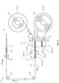
part 30 will be described. As illustrated inFIG. 3 , conveyingpart 30 includes packagingpaper holding part 31, upstream conveyingunit 32, downstream conveyingunit 33, holdingmember 34, cuttingpart 35,base part 36,guide member 37, and connectingpart 38. The broken line arrow inFIG. 3 indicates conveyance direction D1 of first drug packaging paper PP1. - Packaging
paper holding part 31 includes first packagingpaper holding part 31a and second packagingpaper holding part 31b. First packagingpaper holding part 31a rotatably holds roll M1, which is a package of strip-shaped first drug packaging paper PP1 having been folded in half in advance along the longitudinal direction of first drug packaging paper PP1. Second packagingpaper holding part 31b rotatably holds roll M2, which is a package of strip-shaped second drug packaging paper PP2 having been folded in half in advance along the longitudinal direction of second drug packaging paper PP2. The packages of first drug packaging paper PP1 and second drug packaging paper PP2 may be first drug packaging paper PP1 in folds and second drug packaging paper PP2 in folds. - First packaging
paper holding part 31a and second packagingpaper holding part 31b can be exchanged for each other. That is, first packagingpaper holding part 31a can hold roll M2, and second packagingpaper holding part 31b can hold roll M1. In this case, a pair ofrollers 32b described below nip (i.e., hold the drug packaging paper between the rollers) and convey second drug packaging paper PP2, and another pair ofrollers 32d guide first drug packaging paper PP1 without nipping the drug packaging paper. - Upstream conveying
unit 32 includesupstream guide member 32a, a pair ofrollers 32b, anotherupstream guide member 32c, the other pair ofrollers 32d, and movingmember 32e. -
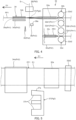
Upstream guide member 32a is configured to guide along conveyance direction D1 first drug packaging paper PP1 fed out from first packagingpaper holding part 31a.Upstream guide member 32a is a plate-shaped member sandwiched by first drug packaging paper PP1. As illustrated inFIGS. 4 and 5 , which are an enlarged view and a side view of upstream conveyingunit 32 and holdingmember 34 and the peripheries thereof,upstream guide member 32a is disposed in such a way that the side surface thereof coinciding with ridge line R1 of first drug packaging paper PP1 is along conveyance direction D1. - The pair of
rollers 32b guide first drug packaging paper PP1 without nipping the drug packaging paper. The pair ofrollers 32b are disposed on the upstream side of first drug packaging paper PP1 fromupstream guide member 32a. The pair ofrollers 32b each have a cylindrical shape. The pair ofrollers 32b include driving roller 32b1 and driven roller 32b2. - Driving roller 32b1 is configured to be rotated by a drive device (not illustrated) such as a motor. Driving roller 32b1 is disposed in such a way that the rotational axis thereof is parallel to the plate surface of
upstream guide member 32a and orthogonal to conveyance direction D1 of first drug packaging paper PP1. - In addition, driving roller 32b1 is configured to move toward driven roller 32b2 to be located at conveying position Pm1, or to move away from driven roller 32b2 to be located at non-conveying position Pm2. When driving roller 32b1 is located at conveying position Pm1, the pair of
rollers 32b can hold first drug packaging paper PP1 or second drug packaging paper PP2 located between the rollers and convey the drug packaging paper toward the downstream side. - Driven roller 32b2 is disposed with the rotational axis thereof inclined. That is, driven roller 32b2 is disposed in such a way that one end part of driven roller 32b2 (on the opened side of first drug packaging paper PP1) is located on the downstream side of first drug packaging paper PP1 from the other end part of driven roller 32b2 (on the ridge line R1 side of first drug packaging paper PP1). In addition, driven roller 32b2 contacts the side surface of first drug packaging paper PP1, thereby having a function of changing conveyance direction D1 (see
FIG. 3 ). - The other
upstream guide member 32c is a plate-shaped member sandwiched by second drug packaging paper PP2 fed out from second packagingpaper holding part 31b. When first drug packaging paper PP1 is being conveyed, the downstream end part of second drug packaging paper PP2 is disposed at the otherupstream guide member 32c. - The other
upstream guide member 32c is disposed in such a way that the plate surface thereof is parallel to the plate surface ofupstream guide member 32a, and the side surface thereof coinciding with ridge line R2 of second drug packaging paper PP2 is located on the same plane as the side surface ofupstream guide member 32a coinciding with ridge line R1. The plate thickness of the otherupstream guide member 32c is approximately the same as the plate thickness ofupstream guide member 32a. As will be described below, at the time of replacing first drug packaging paper PP1 with second drug packaging paper PP2, the otherupstream guide member 32c guides second drug packaging paper PP2. - The other pair of
rollers 32d are disposed on the upstream side of second drug packaging paper PP2 from the otherupstream guide member 32c. The other pair ofrollers 32d are stationary with the downstream end part of second drug packaging paper PP2 located between the rollers. As will be described below, at the time of replacing first drug packaging paper PP1 with second drug packaging paper PP2, the other pair ofrollers 32d nip and convey second drug packaging paper PP2. - The other pair of
rollers 32d each have a cylindrical shape. The other pair ofrollers 32d include driving roller 32d1 and driven roller 32d2. - Driving roller 32d1 is configured to be rotated by a drive device (not illustrated) such as a motor. Driving roller 32d1 is disposed in such a way that the rotational axis thereof is parallel to the plate surface of the other
upstream guide member 32c and orthogonal to conveyance direction D1 of first drug packaging paper PP1. - In addition, driving roller 32d1 is configured to move toward driven roller 32d2 to be located at conveying position Pm1, or to move away from driven roller 32d2 to be located at non-conveying position Pm2. When driving roller 32d1 is located at conveying position Pm1, the other pair of
rollers 32d can hold first drug packaging paper PP1 or second drug packaging paper PP2 located between the rollers and convey the drug packaging paper toward the downstream side. - Driven roller 32d2 is disposed with the rotational axis thereof inclined. That is, driven roller 32d2 is disposed in such a way that one end part of driven roller 32d2 (on the opened side of second drug packaging paper PP2) is located on the downstream side of second drug packaging paper PP2 from the other end part of driven roller 32d2 (on the ridge line R2 side of second drug packaging paper PP2). In addition, driven roller 32d2 contacts the side surface of second drug packaging paper PP2, thereby having a function of changing the conveyance direction of second drug packaging paper PP2.
- Moving
member 32e is configured to be able to moveupstream guide member 32a, the pair ofrollers 32b, the otherupstream guide member 32c, and the other pair ofrollers 32d, at the time of replacing first drug packaging paper PP1 with second drug packaging paper PP2, as described below.Upstream guide member 32a, the pair ofrollers 32b, the otherupstream guide member 32c, and the other pair ofrollers 32d are disposed in movingmember 32e. Movingmember 32e slides between first guide position Pd1 illustrated inFIG. 4 and second guide position Pd2 illustrated inFIG. 8 , which will be referred to. - First guide position Pd1 is a position of moving
member 32e during the conveyance of first drug packaging paper PP1. When movingmember 32e is at first guide position Pd1, the pair ofrollers 32b guide first drug packaging paper PP1 without nipping first drug packaging paper PP1, andupstream guide member 32a guides first drug packaging paper PP1. Second guide position Pd2 is a position of movingmember 32e when the other pair ofrollers 32d nip and convey second drug packaging paper PP2 and the otherupstream guide member 32c guides second drug packaging paper PP2 at the time of replacing first drug packaging paper PP1 with second drug packaging paper PP2, as described below,. The position of the otherupstream guide member 32c when movingmember 32e is located at second guide position Pd2 is the same as the position ofupstream guide member 32a when movingmember 32e is located at first guide position Pd1 (seeFIGS. 4 and8 ). - Returning to
FIG. 3 , the description will be continued. Downstream conveyingunit 33 is configured to convey first drug packaging paper PP1 guided by upstream conveyingunit 32 toprinter 15 and sealingdevice 16. Downstream conveyingunit 33 conveys first drug packaging paper PP1 in such a way that first drug packaging paper PP1 receives a drug at drug delivery position Pr. - Downstream conveying
unit 33 includes a pair ofdownstream rollers 33a that nip and convey first drug packaging paper PP1, a plurality ofrollers 33b that change conveyance direction D1 of first drug packaging paper PP1, anddownstream guide member 33c. -
Downstream guide member 33c is a plate-shaped member sandwiched by first drug packaging paper PP1, and configured to guide first drug packaging paper PP1 to drug delivery position Pr.Downstream guide member 33c is disposed in such a way that the plate surface thereof is orthogonal to the horizontal direction. First drug packaging paper PP1 hold, in its inside,downstream guide member 33c with the opened side of the drug packaging paper facing upward (herein, "in its inside" does not necessarily mean that a component is completely in the inside of another component). First drug packaging paper PP1 is opened upward by being guided bydownstream guide member 33c, and receives a drug led out fromhopper 13b at drug delivery position Pr. - Holding
member 34 is disposed between upstream conveyingunit 32 and downstream conveyingunit 33. Holdingmember 34 does not hold first drug packaging paper PP1 when conveyingpart 30 is conveying first drug packaging paper PP1. Holdingmember 34 holds first drug packaging paper PP1 between the members thereof when first drug packaging paper PP1 is to be replaced with second drug packaging paper PP2, as described below. Holdingmember 34 is composed of a pair ofplate members plate members upstream guide member 32a. As illustrated inFIG. 4 ,first plate member 34a andsecond plate member 34b are configured to be located at holding position Ps1 where the members hold first drug packaging paper PP1 therebeteen or at a non-holding position Ps2 where the members does not hold first drug packaging paper PP1 therebeteen. - Cutting
part 35 cuts first drug wrapping paper PP1 when first drug packaging paper PP1 is to be replaced with second drug packaging paper PP2, as described below. Cuttingpart 35 includes a blade for cutting first drug packaging paper PP1. At a location between holdingmember 34 and upstream conveyingunit 32, cuttingpart 35 cuts first drug packaging paper PP1 on plane S orthogonal to conveyance direction D1. -
Base part 36 is disposed on the opposite side of cuttingpart 35 with first drug packaging paper PP1 therebetween, and has a rectangular parallelepiped shape having a facing surface that faces the side surface of first drug packaging paper PP1. - As illustrated in
FIG. 6 , cuttingpart 35 is configured to be located at cutting position Pc1 where cuttingpart 35 cuts first drug packaging paper PP1 by moving toward first drug packaging paper PP1 or at a non-cutting position Pc2 that is away from first drug packaging paper PP1. In addition,base part 36 is configured to be located at contact position Pb1 where the facing surface of the base part is brought into contact with first drug packaging paper PP1 by moving toward first drug packaging paper PP1 or at non-contact position Pb2 where the facing surface is away from first drug packaging paper PP1. The facing surface ofbase part 36 comes into contact with the cutting edge of cuttingpart 35 at the time of cutting first drug packaging paper PP1 by cuttingpart 35.FIG. 7 is a side view illustrating first drug packaging paper PP1 and the periphery thereof at the time of cutting first drug packaging paper PP1. -
Guide member 37 is disposed between holdingmember 34 and upstream conveyingunit 32, as illustrated inFIGS. 3 to 5 , and configured to guide second drug packaging paper PP2 when first drug packaging paper PP1 is to be replaced with second drug packaging paper PP2, as described below. Specifically,guide member 37 is disposed between plane S andupstream guide member 32a.Guide member 37 is a plate-shaped member. The plate thickness ofguide member 37 is substantially the same as the plate thicknesses ofupstream guide member 32a and the otherupstream guide member 32c. - During the conveyance of first drug packaging paper PP1 by upstream conveying
unit 32 and downstream conveyingunit 33,guide member 37 is located at non-guide position Pg2-a position where the guide member does not contact first drug packaging paper PP1, as illustrated inFIG. 5 . As illustrated inFIGS. 8 and 9 indicating the state in which movingmember 32e has moved, at the time of replacing first drug packaging paper PP1 with second drug packaging paper PP2,guide member 37 is located at guide position Pg1-a position where the guide member can guide second drug packaging paper PP2. That is,guide member 37 is configured to be movable between guide position Pg1 and non-guide position Pg2.Guide member 37 includesinclined part 37a and recessedpart 37b. -
Inclined part 37a is a side portion ofguide member 37, and ridge line R2 of second drug packaging paper PP2 overlaps the side portion at the time of guiding second drug packaging paper PP2 byguide member 37.Inclined part 37a extends in a direction substantially parallel to ridge line R2 of second drug packaging paper PP2 guided byguide member 37. Specifically, inclinedpart 37a has a shape such that the inclined part is inclined from the opened side toward the ridge line R2 side of second drug packaging paper PP2 as the inclined part approaches the downstream side from the upstream side of second drug packaging paper PP2.Inclined part 37a has a flat shape.Inclined part 37a may have a triangular cross section or an arcuate cross section. - Recessed
part 37b is a portion recessed approximately along conveyance direction D1 from the side portion (downstream in conveyance direction D1) ofguide member 37. - Connecting
part 38 is disposed on the same side as cuttingpart 35 when viewed from first drug packaging paper PP1, and has a rectangular parallelepiped shape having a facing surface that faces the side surface of first drug packaging paper PP1. Connectingpart 38 connects the downstream end part of second drug packaging paper PP2 to first drug packaging paper PP1 when first drug packaging paper PP1 is to be replaced with second drug packaging paper PP2, as described below. Connectingpart 38 includes pressingpart 38a configured to press connecting member T. Connecting member T is configured to connect first drug packaging paper PP1 with second drug packaging paper PP2. Pressingpart 38a is a facing surface that faces the side surface of first drug packaging paper PP1. - Connecting member T is, for example, an adhesive tape. In a state where second drug packaging paper PP2 is disposed at the other
upstream guide member 32c, connecting member T is attached to the downstream end part of second drug packaging paper PP2 so as to protrude from the downstream end of the drug packaging paper. Connecting members T are attached to both outer surfaces of second drug packaging paper PP2, which is folded in half. Connecting member T may be an adhesive applied to the inside of the downstream end part of second drug packaging paper PP2. - Connecting
part 38 is configured to be located at first pressing position Po1 (seeFIG. 12 ), second pressing position Po2 (seeFIG. 6 ), or a non-pressing position Po3 (seeFIG. 4 ). - First pressing position Po1 (see
FIG. 12 ) of connectingpart 38 is a position wherepressing part 38a andbase part 36 located atcontact position Pb 1 hold first drug packaging paper PP1, second drug wrapping paper PP2, and connecting member T therebetween and press them at the time of connecting first drug packaging paper PP1 with second drug packaging paper PP2, as described below. - Second pressing position Po2 (see
FIG.6 ) of connectingpart 38 is a position wherepressing part 38a andbase part 36 located at contact position Pb1 hold first drug packaging paper PP1 therebetween and press first drug packaging paper PP1 at the time of cutting first drug packaging paper PP1 by cuttingpart 35, as described below. Second pressing position Po2 is on the upstream side of first drug packaging paper PP1 from plane S. - Non-pressing position Po3 of connecting
part 38 is a position where connectingpart 38 is separated from first drug packaging paper PP1 and thus does not press first drug packaging paper PP1. - In the following, the operation of
drug supply apparatus 1 when first drug packaging paper PP1 is to be replaced with second drug packaging paper PP2 will be described. - As illustrated
FIGS. 3 to 5 , when conveyingpart 30 is conveying first drug packaging paper PP1, drivingroller 32bfirst plate member 34a of holdingmember 34 is located at the non-holding position Ps2, and cuttingpart 35 is located at non-cutting position Pc2. In addition,base part 36 is located at non-contact position Pb2, connectingpart 38 is located at non-pressing position Po3, and guidemember 37 is located at non-guide position Pg2. In addition,upstream guide member 32a guides first drug packaging paper PP1 while being sandwiched by first drug packaging paper PP1. - When the control part detects that first drug packaging paper PP1 is running low, the control part stops the operation of
drug supply unit 13 and also stops the operation of the pair ofdownstream rollers 33a. The control part detects that first drug packaging paper PP1 is running low, for example, based on a detection signal from a sensor (for example, an infrared sensor) detecting the outer diameter of roll M1 or from a sensor detecting the tension of first drug packaging paper PP1. The sensor detecting the tension of first drug packaging paper PP1 is, for example, a load sensor that detects the force acting onroller 33b of downstream conveyingunit 33. The tension of first drug packaging paper PP1 increases as the amount of first drug packaging paper PP1 decreases. - In addition, the following configuration is also possible: when the tension of first drug packaging paper PP1 increases,
roller 33b moves, and the control part detects that first drug packaging paper PP1 is running low based on a detection signal from a position sensor detecting the position ofroller 33b. - Subsequently, as illustrated in
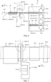
FIG. 6 , the control part movesfirst plate member 34a to holding position Ps1. As a result, holdingmember 34 holds first drug packaging paper PP1 between the members thereof. Further, the control part movesbase part 36 to contact position Pb1 and moves connectingpart 38 to second pressing position Po2. As a result,base part 36 and connectingpart 38 hold first drug packaging paper PP1 therebetween at a location between holdingmember 34 and upstream conveyingunit 32. - The control part then cuts first drug packaging paper PP1 at cutting position Pc1 by moving cutting
part 35 in a direction orthogonal to conveyance direction D1. Solid line L along plane S illustrated inFIG. 7 represents the ends of first drug packaging paper PP1 formed when first drug packaging paper PP1 is cut (the ends being the upstream end on the side held by holdingmember 34 and the downstream end on the side held bybase part 36 and connecting part 38). On the upstream side from plane S, first drug packaging paper PP1 is held bybase part 36 and connectingpart 38. On the downstream side from plane S, first drug packaging paper PP1 is held by holdingmember 34. Therefore, cuttingpart 35 can reliably cut first drug packaging paper PP1 in a straight line without shifting the position of first drug packaging paper PP1. - When cutting
part 35 finishes the cutting, the control partpositions cutting part 35 at non-cutting position Pc2, moves connectingpart 38 to non-pressing position Po3, and movesbase part 36 to non-contact position Pb2. - Subsequently, the control part moves driving roller 32d1 of the other pair of
rollers 32d so that the other pair ofrollers 32d hold the downstream end part of second drug packaging paper PP2 therebetween. In this state, the control part moves movingmember 32e from first guide position Pd1 to second guide position Pd2, as illustrated inFIGS. 8 and 9 . The otherupstream guide member 32c is thus located at the position whereupstream guide member 32a has been located before movingmember 32e moves. In addition, the downstream end part of second drug packaging paper PP2 faces the upstream end part of first drug packaging paper PP1. - The control part further moves
guide member 37 to guide position Pg1. As a result,guide member 37 andupstream guide member 32a face each other. Subsequently, the control part rotates driving roller 32d1 to convey second drug packaging paper PP2. - As illustrated in
FIG. 9 , driven roller 32d2 is disposed at an angle. Specifically, driven roller 32d2 is disposed in such a way that one end part of driven roller 32d2 (on the opened side of second drug packaging paper PP2) is located on the downstream side of second drug packaging paper PP2 from the other end part of driven roller 32d2 (on the ridge line R2 side of second drug packaging paper PP2). Therefore, the other pair ofrollers 32d convey second drug packaging paper PP2 in a direction inclined with respect to conveyance direction D1 of first drug packaging paper PP1. - Specifically, the other pair of
rollers 32d convey second drug packaging paper PP2 in such a way that the opened side of the downstream end part of second drug packaging paper PP2 approaches the ridge line R1 side of the upstream end part of first drug packaging paper PP1. When second drug packaging paper PP2 is conveyed to guidemember 37, second drug packaging paper PP2 is guided byguide member 37. Describing with reference to the state illustrated inFIG. 9 ,guide member 37 guides second drug packaging paper PP2 in such a way that as second drug packaging paper PP2 moves leftward, the left end of second drug packaging paper PP2 moves upward. - That is, second drug packaging paper PP2 is guided by
inclined part 37a ofguide member 37 in such a way that as the downstream end part of second drug packaging paper PP2 approaches the upstream end part of first drug packaging paper PP1, the opened side of the downstream end part of second drug packaging paper PP2 approaches the ridge line R1 side of the upstream end part of first drug packaging paper PP1. In other words, the direction in which inclinedpart 37a guides second drug packaging paper PP2 is approximately the same as the direction in which the other pair ofrollers 32d convey second drug packaging paper PP2. Therefore, second drug packaging paper PP2 is smoothly conveyed and guided without being caught byinclined part 37a. In addition,guide member 37 includes recessedpart 37b, thereby reducing contact of connecting member T withguide member 37. - As second drug packaging paper PP2 is conveyed and guided as described above, when second drug packaging paper PP2 is conveyed to the downstream end part of first drug packaging paper PP1, ridge line R2 of second drug packaging paper PP2 is located above ridge line R1 of first drug packaging paper PP1. As illustrated in
FIG. 10 , a longitudinal cross-sectional view ofguide member 37 and a periphery thereof, second drug packaging paper PP2 is wider than the plate thickness ofguide member 37. The downstream end part of second drug packaging paper PP2 thus holds in its inside the upstream end part of first drug packaging paper PP1, and ridge line R2 of second drug packaging paper PP2 overlaps ridge line R1 of first drug packaging paper PP1, as illustrated inFIG. 11 . Second drug packaging paper PP2 is thus smoothly conveyed and guided without the downstream end part of second drug packaging paper PP2 bumping into the upstream end part of first drug packaging paper PP1. - At this time, first drug packaging paper PP1 is held by holding
member 34 between the members thereof. Therefore, even when the moving second drug packaging paper PP2 or the moving connecting member T comes into contact with first drug packaging paper PP1, first drug packaging paper PP1 can stay at a predetermined position without shifting to the downstream side. - That is, upstream conveying
unit 32 conveys second drug packaging paper PP2 in such a way that the opened side of the downstream end part of second drug packaging paper PP2 approaches the ridge line R1 side of the upstream end part of first drug packaging paper PP1. In addition, upstream conveyingunit 32 conveys second drug packaging paper PP2 toward first drug packaging paper PP1 in such a way that the downstream end part of second drug packaging paper PP2 holds in its inside the upstream end part of first drug packaging paper PP1, and ridge line R2 of second drug packaging paper PP2 overlaps ridge line R1 of first drug packaging paper PP1. Therefore, in the case of replacing packaging paper, second drug packaging paper PP2 is smoothly conveyed to overlap first drug packaging paper PP1 while preventing the generation of folds in first drug packaging paper PP1 and second drug packaging paper PP2. - The control part stops the operation of the pair of
rollers 32b in response to the downstream end part of second drug packaging paper PP2 overlapping the upstream end part of first drug packaging paper PP1. The control part detects that the downstream end part of second drug packaging paper PP2 overlaps the upstream end part of first drug packaging paper PP1 based on a detection signal from a position sensor (for example, an infrared sensor) detecting the position of second drug packaging paper PP2. - Subsequently, the control part positions guide
member 37 at non-guide position Pg2. Furthermore, the control part positions basepart 36 at contact position Pb1 and connectingpart 38 at first pressing position Po1, as illustrated inFIG. 12 . As a result, connecting member T is located betweenbase part 36 and connectingpart 38 and pressed, thereby connecting first drug packaging paper PP1 with second drug packaging paper PP2. - The control part then positions connecting
part 38 at non-pressing position Po3,base part 36 at non-contact position Pb2,first plate member 34a at non-holding position Ps2, and driving roller 32d1 at non-conveying position Pm2, as illustrated inFIG. 13 . - Further, when first drug packaging paper PP1 is conveyed by the pair of
downstream rollers 33a due to the operation by the control part, second drug packaging paper PP2 connected to first drug packaging paper PP1 is also conveyed. When first drug packaging paper PP1 is consumed, the packaging paper conveyed by conveyingpart 30 is switched to second drug packaging paper PP2. In addition, the downstream end part of second drug packaging paper PP2 holds, in its inside, the upstream end part of first drug packaging paper PP1; therefore, the upstream end of second drug packaging paper PP2 is not caught bydownstream guide member 33c. Therefore, switching to second drug packaging paper PP2 is performed smoothly. - As described above,
drug supply apparatus 1 automatically replaces first drug packaging paper PP1 with second drug packaging paper PP2. Therefore, it is possible to improve the efficiency and shorten the time required to replace packaging paper. In addition, roll M2 is held by second packagingpaper holding part 31b, and the downstream end part of second drug packaging paper PP2 is disposed at the otherupstream guide member 32c. Such a configuration allows the control part to convey second drug packaging paper PP2 to connect second drug packaging paper PP2 to first drug packaging paper PP1 in response to first drug packaging paper PP1 being running low, without waiting for the supply of roll M2 of second drug packaging paper PP2. - Even after first drug packaging paper PP1 is replaced with second drug packaging paper PP2, first drug packaging paper PP1 is placed at upstream conveying
unit 32 and is held in first packagingpaper holding part 31a, as illustrated inFIG. 12 . Before second drug packaging paper PP2 runs low, an operator replaces first drug packaging paper PP1 (placed at upstream conveyingunit 32 and in first packagingpaper holding part 31a) with a new roll M1 of first drug packaging paper PP1. -
Drug supply apparatus 1 may notify an operator that the packaging paper has been replaced by, for example, displaying a message on a display or sounding a buzzer. In response to the notification, the operator replaces roll M1 with a new roll. - Specifically, the operator removes first drug packaging paper PP1 from first packaging
paper holding part 31a and attaches a new roll M1. The operator then disposes the downstream end part (fed out from the new roll M1) of first drug packaging paper PP1 atupstream guide member 32a, as illustrated inFIG. 13 . Subsequently, the operator attaches connecting member T to the downstream end part of first drug packaging paper PP1 so as to protrude from the downstream end of the drug packaging paper. - When the control part detects that second drug packaging paper PP2 is running low, for example, based on the detection signal of the position sensor described above, the control part automatically replaces second drug packaging paper PP2 with the new first drug packaging paper PP1 in the same manner as when the old first drug packaging paper PP1 is automatically replaced with second drug packaging paper PP2 as described above. When the control part replaces second drug packaging paper PP2 with a new first drug packaging paper PP1, conveying
part 30 conveys the new first drug packaging paper PP1 as in the state illustrated inFIG. 3 . - The present disclosure is not limited to the embodiment described above. Various variations derived from the present embodiment are also included within the scope of the present disclosure, as long as those variations do not depart from the spirit of the present disclosure.
- For example, first drug packaging paper PP1 and second drug packaging paper PP2 may be connected to each other by heat sealing. In this case, connecting
part 38 is configured to include a heater. It is not necessary to attach connecting member T to second drug packaging paper PP2. - First drug packaging paper PP1 and second drug packaging paper PP2 may be connected to each other without being overlapping. The downstream end part of second drug packaging paper PP2 may be connected to a portion other than the upstream end part of first drug packaging paper PP1.
- In the pairs of
rollers 32b androllers 32d, not only driven rollers 32b2 and 32d2 but also drivingrollers 32b - When first drug packaging paper PP1 is to be replaced with second drug packaging paper PP2, second drug packaging paper PP2 may be conveyed along conveyance direction D1. In this case, driven rollers 32b2 and 32d2 may be disposed so that the rotational axes of the rollers are orthogonal to conveyance direction D1, that is, not inclined.
- As illustrated in
FIG. 14 , the following configuration is also possible: the circumferential side surface of driven roller 132d2 is tapered surface TS in which the circumferential length on the opened side of second drug packaging paper PP2 is longer than the circumferential length on the ridge line R2 side of second drug packaging paper PP2. Driven roller 132d2 is disposed in such a way that the rotational axis thereof is orthogonal to conveyance direction D1 of first drug packaging paper PP1, and tapered surface TS is in line contact with the side surface of second drug packaging paper PP2. Due to this tapered surface TS, second drug packaging paper PP2 is conveyed in such a way that the opened side of the downstream end part of second drug packaging paper PP2 approaches the ridge line R1 side of the upstream end part of first drug packaging paper PP1. At least one of the circumferential side surfaces of driven roller 32b2 and driving rollers 32b1 and 32d1 may be tapered surface TS. - In addition, conveying
part 30 does not need to include second packagingpaper holding part 31b, the otherupstream guide member 32c, the other pair ofrollers 32d, and movingmember 32e. In this case, at the time of replacing first drug packaging paper PP1 with second drug packaging paper PP2, the control partpositions cutting part 35 at non-cutting position Pc2 after cutting first drug packaging paper PP1, moves connectingpart 38 to non-pressing position Po3, and movesbase part 36 to non-contact position Pb2. In this state, the control part stops the operation of conveyingpart 30. At this time, the control part may notify an operator of the request for replacement of the roll by, for example, displaying a message on a display. - The operator then removes first drug packaging paper PP1 from first packaging
paper holding part 31a and attaches roll M2 of second drug packaging paper PP2 to first packagingpaper holding part 31a. The operator further disposes the downstream end part of second drug packaging paper PP2 atupstream guide member 32a, and attaches connecting member T to the downstream end part of second drug packaging paper PP2. - Subsequently, the operator inputs information, indicating that the attachment of the roll has been completed, on
operation part 11. In response, the control part moves guidemember 37 to guide position Pg1 andpositions driving 1 at conveying position Pm1. The control part further rotates driving roller 32b1 to convey second drug packaging paper PP2. As a result, second drug packaging paper PP2 is conveyed and guided as described above and connected to first drug packaging paper PP1 by connectingroller 32bpart 38. Downstream conveyingunit 33 conveys first drug packaging paper PP1 as described above, and thus first drug packaging paper PP1 is replaced with second drug packaging paper PP2. - In addition,
drug supply apparatus 1 does not need to include cuttingpart 35. In this case, the operator manually cuts first drug packaging paper PP1, and while the operator performs the cutting work, the control part stops the operation of conveyingpart 30 configured to replace packaging paper. - In addition,
drug supply apparatus 1 does not need to include connectingpart 38. In this case, the operator manually connects first drug packaging paper PP1 with second drug packaging paper PP2, and while the operator performs the connecting work, the control part stops the operation of conveyingpart 30 configured to replace packaging paper. - This application is entitled to and claims the benefit of
Japanese Patent Application No. 2021-159486 filed on September 29, 2021 - The present disclosure is widely available for drug supply apparatuses.
-
- 1 Drug supply apparatus
- 13 Drug supply unit
- 30 Conveying part
- 31 Packaging paper holding part
- 32 Upstream conveying unit
- 32e Moving member
- 33 Downstream conveying unit
- 35 Cutting part
- 37 Guide member
- 38 Connecting part
- 38a Pressing part
- M1 Roll
- M2 Roll
- PP1 First drug packaging paper
- PP2 Second drug packaging paper
- Pr Drug delivery position
- R1 Ridge line of first drug packaging paper
- R2 Ridge line of second drug packaging paper
- T Connecting member
- TS Tapered surface
Claims (7)
- A drug supply apparatus, comprising:a drug supply unit configured to supply a drug to a drug delivery position;a downstream conveying unit configured to convey a first drug packaging paper in such a way that the first drug packaging paper receives the drug at the drug delivery position, wherein the first drug packaging paper is strip shaped and folded in half in advance along a longitudinal direction of the first drug packaging paper;an upstream conveying unit configured to convey a second drug packaging paper toward the first drug packaging paper, wherein the second drug packaging paper is strip shaped and folded in half in advance along a longitudinal direction of the second drug packaging paper; anda connecting part configured to connect a downstream end part of the second drug packaging paper to the first drug packaging paper.
- The drug supply apparatus according to claim 1, further comprising:
a packaging paper holding part configured to hold a package of the second drug packaging paper. - The drug supply apparatus according to claim 2, wherein
the packaging paper holding part is configured to further hold a package of the first drug packaging paper. - The drug supply apparatus according to any one of claims 1 to 3, wherein
the connecting part includes a pressing part configured to press a connecting member that is configured to connect the first drug packaging paper with the second drug packaging paper. - The drug supply apparatus according to any one of claims 1 to 4, further comprising:a cutting part configured to cut the first drug packaging paper, whereinthe connecting part connects the downstream end part of the second drug packaging paper to an upstream end part of the first drug packaging paper, the upstream end part being formed when the cutting part cuts the first drug packaging paper.
- The drug supply apparatus according to claim 5, wherein
the upstream conveying unit conveys the second drug packaging paper in such a way that the downstream end part of the second drug packaging paper holds, in an inside of the downstream end part, the upstream end part of the first drug packaging paper, and a ridge line of the second drug packaging paper overlaps a ridge line of the first drug packaging paper. - The drug supply apparatus according to claim 5 or 6, wherein
the upstream conveying unit includes a moving member configured to move the second drug packaging paper in such a way that the downstream end part of the second drug packaging paper faces the upstream end part of the first drug packaging paper.
Applications Claiming Priority (2)
| Application Number | Priority Date | Filing Date | Title |
|---|---|---|---|
| JP2021159486 | 2021-09-29 | ||
| PCT/JP2022/035218 WO2023054129A1 (en) | 2021-09-29 | 2022-09-21 | Drug supply device |
Publications (3)
| Publication Number | Publication Date |
|---|---|
| EP4393830A1 true EP4393830A1 (en) | 2024-07-03 |
| EP4393830A4 EP4393830A4 (en) | 2025-01-22 |
| EP4393830B1 EP4393830B1 (en) | 2026-01-21 |
Family
ID=85780662
Family Applications (1)
| Application Number | Title | Priority Date | Filing Date |
|---|---|---|---|
| EP22875996.5A Active EP4393830B1 (en) | 2021-09-29 | 2022-09-21 | Drug supply device |
Country Status (5)
| Country | Link |
|---|---|
| US (1) | US12612200B2 (en) |
| EP (1) | EP4393830B1 (en) |
| JP (1) | JP7636571B2 (en) |
| CN (1) | CN117980232A (en) |
| WO (1) | WO2023054129A1 (en) |
Families Citing this family (2)
| Publication number | Priority date | Publication date | Assignee | Title |
|---|---|---|---|---|
| WO2022105654A1 (en) * | 2020-11-23 | 2022-05-27 | 无锡先导智能装备股份有限公司 | Roll changing apparatus, winding device and gluing device |
| EP4393831A4 (en) * | 2021-09-29 | 2025-05-14 | PHC Holdings Corporation | Chemical agent supply device |
Family Cites Families (33)
| Publication number | Priority date | Publication date | Assignee | Title |
|---|---|---|---|---|
| US3473994A (en) * | 1963-12-27 | 1969-10-21 | Continental Can Co | Film splicing mechanism |
| US3753833A (en) * | 1970-02-16 | 1973-08-21 | Butler Automatic Inc | Web supply apparatus |
| US3880698A (en) * | 1971-11-05 | 1975-04-29 | Toppan Containers Co Ltd | Continuously feeding apparatus for rolled webs |
| US4157934A (en) * | 1977-07-18 | 1979-06-12 | Compensating Tension Controls, Inc. | Low tension lap slicer unit |
| US4190475A (en) * | 1978-05-16 | 1980-02-26 | Marquip, Inc. | Paper roll web splicing |
| US4219378A (en) * | 1979-04-16 | 1980-08-26 | Marquip, Inc. | Web splicing |
| JPS5859146A (en) * | 1981-09-30 | 1983-04-08 | Rengo Co Ltd | Adding method of paper and its device |
| JPS5916805U (en) | 1982-07-21 | 1984-02-01 | 三洋電機株式会社 | Continuous wrapping paper feeding device |
| DD239191A1 (en) * | 1985-07-12 | 1986-09-17 | Polygraph Leipzig | DEVICE FOR FEEDING MATERIALS |
| IT1186633B (en) * | 1985-10-11 | 1987-12-04 | Gd Spa | DEVICE TO JOIN THE FINAL END OF A TAPE WRAPPED IN A REEL EXHAUST WITH THE INITIAL END OF A NEW REEL |
| DE3903792A1 (en) * | 1989-02-09 | 1990-08-16 | Tetra Pak Gmbh | DEVICE FOR FLYING CHANGE FROM A FIRST DRUM TO A SECOND DRUM |
| DE3937286A1 (en) * | 1989-11-09 | 1991-05-16 | Hoechst Ag | TAPE CHANGE DEVICE |
| US5064488A (en) * | 1990-03-27 | 1991-11-12 | Trine Manufacturing Company, Inc. | Apparatus and method for splicing film |
| IT227176Y1 (en) * | 1992-11-11 | 1997-09-15 | Ocme Srl | DEVICE FOR THE JOINT OF THERMO-EXTRACTABLE PLASTIC FILM IN A MACHINE USING THIS FILM |
| US5514237A (en) * | 1993-10-05 | 1996-05-07 | The Procter & Gamble Company | Heat splicing of thermoplastic film |
| NL1016442C2 (en) * | 2000-10-19 | 2002-04-22 | Fuji Seal Europe Bv | Method and device for joining together the end of a plastic film hose squashed with the start of a subsequent hose. |
| FR2823190B1 (en) * | 2001-04-10 | 2003-09-05 | Cermex Ouest Conditionnement | METHOD FOR RECHARGING A WRAPPER WITH A PLASTIC FILM, AND WRAPPER IMPLEMENTING THE METHOD |
| US20030188517A1 (en) * | 2002-04-09 | 2003-10-09 | Mars Incorporated | Apparatus and method for forming and filling pouches of varying dimensions |
| AT500126B1 (en) * | 2003-11-04 | 2007-05-15 | Deininger Karl Dipl Ing | METHOD FOR REPLACING TUBE ROLLERS, ESPECIALLY FOR SIDE HOLDING HOSES |
| ITTO20050823A1 (en) * | 2005-11-21 | 2007-05-22 | Fameccanica Data Spa | DEVICE FOR JUNCTION OF TAPE MATERIAL |
| US7803242B2 (en) * | 2007-06-14 | 2010-09-28 | Boeing Company | Apparatus and method for splicing an elongate multi-layered workpiece |
| JP5353096B2 (en) | 2008-07-22 | 2013-11-27 | 株式会社湯山製作所 | Wrapping paper connection device, wrapping paper connection method, and packaging device |
| JP5577526B2 (en) * | 2010-09-24 | 2014-08-27 | 高園テクノロジー株式会社 | Wrapping paper connection device |
| JP5782309B2 (en) * | 2011-06-30 | 2015-09-24 | パナソニックヘルスケアホールディングス株式会社 | Drug packaging device |
| JP5994644B2 (en) | 2012-01-13 | 2016-09-21 | 株式会社湯山製作所 | Wrapping paper joining apparatus and joining method |
| JP6108686B2 (en) * | 2012-05-23 | 2017-04-05 | 株式会社タカゾノ | Drug packaging device |
| ITVR20130163A1 (en) * | 2013-07-16 | 2015-01-17 | Sacmi Verona Spa | SUPPORT GROUP FOR SUPPORTING TAPES FOR LABELING OF PRODUCTS TO BE LABELED |
| WO2016047295A1 (en) * | 2014-09-25 | 2016-03-31 | 株式会社湯山製作所 | Medicine inspection assistance device |
| JP5983712B2 (en) * | 2014-11-21 | 2016-09-06 | 株式会社湯山製作所 | Wrapping paper connection device, wrapping paper connection method, and packaging device |
| JP7454837B2 (en) | 2020-02-03 | 2024-03-25 | 三光機械株式会社 | Packaging film joining equipment and packaging film automatic exchange equipment |
| JP7390010B2 (en) | 2020-04-01 | 2023-12-01 | 株式会社大一商会 | gaming machine |
| EP3967637B1 (en) * | 2020-09-14 | 2023-11-29 | Harro Höfliger Verpackungsmaschinen GmbH | Device and method for splicing and continuously providing a film sheet |
| EP4393831A4 (en) * | 2021-09-29 | 2025-05-14 | PHC Holdings Corporation | Chemical agent supply device |
-
2022
- 2022-09-21 EP EP22875996.5A patent/EP4393830B1/en active Active
- 2022-09-21 CN CN202280063608.1A patent/CN117980232A/en active Pending
- 2022-09-21 JP JP2023551390A patent/JP7636571B2/en active Active
- 2022-09-21 WO PCT/JP2022/035218 patent/WO2023054129A1/en not_active Ceased
-
2024
- 2024-03-25 US US18/615,842 patent/US12612200B2/en active Active
Also Published As
| Publication number | Publication date |
|---|---|
| JP7636571B2 (en) | 2025-02-26 |
| US20240228087A1 (en) | 2024-07-11 |
| US12612200B2 (en) | 2026-04-28 |
| EP4393830B1 (en) | 2026-01-21 |
| EP4393830A4 (en) | 2025-01-22 |
| WO2023054129A1 (en) | 2023-04-06 |
| CN117980232A (en) | 2024-05-03 |
| JPWO2023054129A1 (en) | 2023-04-06 |
Similar Documents
| Publication | Publication Date | Title |
|---|---|---|
| US12612200B2 (en) | Drug supply apparatus | |
| CN111448153B (en) | Object conveying device | |
| US8834048B2 (en) | Printer with cutter having blade including linerless label supporting portion | |
| CN104221486B (en) | Automatic splicing device | |
| US12397941B2 (en) | Drug supply apparatus | |
| US10189664B1 (en) | Sheet processing apparatus and image forming system | |
| KR100748633B1 (en) | medicine bag conveying apparatus | |
| JP2021079965A (en) | Medicine one-package pack separation device and medicine administration assistance device | |
| US20110163493A1 (en) | Media separator and method | |
| JP3478507B2 (en) | Shredder paper feeder | |
| JP7680007B2 (en) | Collating and packaging system | |
| JP7595340B2 (en) | Packaging Equipment | |
| JP7514564B2 (en) | Packaging Machine | |
| JP2017141110A (en) | Laminate processing automatic feeder | |
| JP7080518B2 (en) | Paper leaf double feed detection device | |
| JP2016037302A (en) | Packaging equipment and packages | |
| JP2013060298A (en) | Paper leaf handling device | |
| JP7126845B2 (en) | Conveying device for conveying sheet-like materials | |
| JP7662180B2 (en) | Packaging Equipment | |
| JP5134940B2 (en) | Dispensing device sheet removal mechanism | |
| JP2023010455A (en) | Collating and packaging system | |
| JP2633186B2 (en) | Tablet packaging equipment | |
| JPH092676A (en) | Paper sheet processor | |
| JPH01127555A (en) | Inverting device for paper | |
| JP2003296664A (en) | Card processing equipment |
Legal Events
| Date | Code | Title | Description |
|---|---|---|---|
| STAA | Information on the status of an ep patent application or granted ep patent |
Free format text: STATUS: THE INTERNATIONAL PUBLICATION HAS BEEN MADE |
|
| PUAI | Public reference made under article 153(3) epc to a published international application that has entered the european phase |
Free format text: ORIGINAL CODE: 0009012 |
|
| STAA | Information on the status of an ep patent application or granted ep patent |
Free format text: STATUS: REQUEST FOR EXAMINATION WAS MADE |
|
| 17P | Request for examination filed |
Effective date: 20240327 |
|
| AK | Designated contracting states |
Kind code of ref document: A1 Designated state(s): AL AT BE BG CH CY CZ DE DK EE ES FI FR GB GR HR HU IE IS IT LI LT LU LV MC MK MT NL NO PL PT RO RS SE SI SK SM TR |
|
| DAV | Request for validation of the european patent (deleted) | ||
| DAX | Request for extension of the european patent (deleted) | ||
| RAP3 | Party data changed (applicant data changed or rights of an application transferred) |
Owner name: PHC HOLDINGS CORPORATION |
|
| A4 | Supplementary search report drawn up and despatched |
Effective date: 20241219 |
|
| RIC1 | Information provided on ipc code assigned before grant |
Ipc: A61J 3/00 20060101ALI20241213BHEP Ipc: B65H 19/18 20060101ALI20241213BHEP Ipc: B65B 41/12 20060101AFI20241213BHEP |
|
| GRAP | Despatch of communication of intention to grant a patent |
Free format text: ORIGINAL CODE: EPIDOSNIGR1 |
|
| STAA | Information on the status of an ep patent application or granted ep patent |
Free format text: STATUS: GRANT OF PATENT IS INTENDED |
|
| INTG | Intention to grant announced |
Effective date: 20250910 |
|
| GRAS | Grant fee paid |
Free format text: ORIGINAL CODE: EPIDOSNIGR3 |
|
| GRAA | (expected) grant |
Free format text: ORIGINAL CODE: 0009210 |
|
| STAA | Information on the status of an ep patent application or granted ep patent |
Free format text: STATUS: THE PATENT HAS BEEN GRANTED |
|
| AK | Designated contracting states |
Kind code of ref document: B1 Designated state(s): AL AT BE BG CH CY CZ DE DK EE ES FI FR GB GR HR HU IE IS IT LI LT LU LV MC MK MT NL NO PL PT RO RS SE SI SK SM TR |
|
| REG | Reference to a national code |
Ref country code: CH Ref legal event code: F10 Free format text: ST27 STATUS EVENT CODE: U-0-0-F10-F00 (AS PROVIDED BY THE NATIONAL OFFICE) Effective date: 20260121 |
|
| REG | Reference to a national code |
Ref country code: DE Ref legal event code: R096 Ref document number: 602022029006 Country of ref document: DE |
|
| REG | Reference to a national code |
Ref country code: NL Ref legal event code: FP |
|
| REG | Reference to a national code |
Ref country code: IE Ref legal event code: FG4D |