EP4393739A1 - Hybrid system and vehicle - Google Patents
Hybrid system and vehicle Download PDFInfo
- Publication number
- EP4393739A1 EP4393739A1 EP22885009.5A EP22885009A EP4393739A1 EP 4393739 A1 EP4393739 A1 EP 4393739A1 EP 22885009 A EP22885009 A EP 22885009A EP 4393739 A1 EP4393739 A1 EP 4393739A1
- Authority
- EP
- European Patent Office
- Prior art keywords
- gear
- gear train
- input
- input shaft
- motor
- Prior art date
- Legal status (The legal status is an assumption and is not a legal conclusion. Google has not performed a legal analysis and makes no representation as to the accuracy of the status listed.)
- Pending
Links
Images







Classifications
-
- F—MECHANICAL ENGINEERING; LIGHTING; HEATING; WEAPONS; BLASTING
- F16—ENGINEERING ELEMENTS AND UNITS; GENERAL MEASURES FOR PRODUCING AND MAINTAINING EFFECTIVE FUNCTIONING OF MACHINES OR INSTALLATIONS; THERMAL INSULATION IN GENERAL
- F16H—GEARING
- F16H3/00—Toothed gearings for conveying rotary motion with variable gear ratio or for reversing rotary motion
- F16H3/02—Toothed gearings for conveying rotary motion with variable gear ratio or for reversing rotary motion without gears having orbital motion
- F16H3/08—Toothed gearings for conveying rotary motion with variable gear ratio or for reversing rotary motion without gears having orbital motion exclusively or essentially with continuously meshing gears, that can be disengaged from their shafts
- F16H3/087—Toothed gearings for conveying rotary motion with variable gear ratio or for reversing rotary motion without gears having orbital motion exclusively or essentially with continuously meshing gears, that can be disengaged from their shafts characterised by the disposition of the gears
- F16H3/089—Toothed gearings for conveying rotary motion with variable gear ratio or for reversing rotary motion without gears having orbital motion exclusively or essentially with continuously meshing gears, that can be disengaged from their shafts characterised by the disposition of the gears all of the meshing gears being supported by a pair of parallel shafts, one being the input shaft and the other the output shaft, there being no countershaft involved
-
- B—PERFORMING OPERATIONS; TRANSPORTING
- B60—VEHICLES IN GENERAL
- B60K—ARRANGEMENT OR MOUNTING OF PROPULSION UNITS OR OF TRANSMISSIONS IN VEHICLES; ARRANGEMENT OR MOUNTING OF PLURAL DIVERSE PRIME-MOVERS IN VEHICLES; AUXILIARY DRIVES FOR VEHICLES; INSTRUMENTATION OR DASHBOARDS FOR VEHICLES; ARRANGEMENTS IN CONNECTION WITH COOLING, AIR INTAKE, GAS EXHAUST OR FUEL SUPPLY OF PROPULSION UNITS IN VEHICLES
- B60K6/00—Arrangement or mounting of plural diverse prime-movers for mutual or common propulsion, e.g. hybrid propulsion systems comprising electric motors and internal combustion engines
- B60K6/20—Arrangement or mounting of plural diverse prime-movers for mutual or common propulsion, e.g. hybrid propulsion systems comprising electric motors and internal combustion engines the prime-movers consisting of electric motors and internal combustion engines, e.g. HEVs
- B60K6/22—Arrangement or mounting of plural diverse prime-movers for mutual or common propulsion, e.g. hybrid propulsion systems comprising electric motors and internal combustion engines the prime-movers consisting of electric motors and internal combustion engines, e.g. HEVs characterised by apparatus, components or means specially adapted for HEVs
- B60K6/24—Arrangement or mounting of plural diverse prime-movers for mutual or common propulsion, e.g. hybrid propulsion systems comprising electric motors and internal combustion engines the prime-movers consisting of electric motors and internal combustion engines, e.g. HEVs characterised by apparatus, components or means specially adapted for HEVs characterised by the combustion engines
-
- B—PERFORMING OPERATIONS; TRANSPORTING
- B60—VEHICLES IN GENERAL
- B60K—ARRANGEMENT OR MOUNTING OF PROPULSION UNITS OR OF TRANSMISSIONS IN VEHICLES; ARRANGEMENT OR MOUNTING OF PLURAL DIVERSE PRIME-MOVERS IN VEHICLES; AUXILIARY DRIVES FOR VEHICLES; INSTRUMENTATION OR DASHBOARDS FOR VEHICLES; ARRANGEMENTS IN CONNECTION WITH COOLING, AIR INTAKE, GAS EXHAUST OR FUEL SUPPLY OF PROPULSION UNITS IN VEHICLES
- B60K6/00—Arrangement or mounting of plural diverse prime-movers for mutual or common propulsion, e.g. hybrid propulsion systems comprising electric motors and internal combustion engines
- B60K6/20—Arrangement or mounting of plural diverse prime-movers for mutual or common propulsion, e.g. hybrid propulsion systems comprising electric motors and internal combustion engines the prime-movers consisting of electric motors and internal combustion engines, e.g. HEVs
- B60K6/22—Arrangement or mounting of plural diverse prime-movers for mutual or common propulsion, e.g. hybrid propulsion systems comprising electric motors and internal combustion engines the prime-movers consisting of electric motors and internal combustion engines, e.g. HEVs characterised by apparatus, components or means specially adapted for HEVs
- B60K6/26—Arrangement or mounting of plural diverse prime-movers for mutual or common propulsion, e.g. hybrid propulsion systems comprising electric motors and internal combustion engines the prime-movers consisting of electric motors and internal combustion engines, e.g. HEVs characterised by apparatus, components or means specially adapted for HEVs characterised by the motors or the generators
-
- B—PERFORMING OPERATIONS; TRANSPORTING
- B60—VEHICLES IN GENERAL
- B60K—ARRANGEMENT OR MOUNTING OF PROPULSION UNITS OR OF TRANSMISSIONS IN VEHICLES; ARRANGEMENT OR MOUNTING OF PLURAL DIVERSE PRIME-MOVERS IN VEHICLES; AUXILIARY DRIVES FOR VEHICLES; INSTRUMENTATION OR DASHBOARDS FOR VEHICLES; ARRANGEMENTS IN CONNECTION WITH COOLING, AIR INTAKE, GAS EXHAUST OR FUEL SUPPLY OF PROPULSION UNITS IN VEHICLES
- B60K6/00—Arrangement or mounting of plural diverse prime-movers for mutual or common propulsion, e.g. hybrid propulsion systems comprising electric motors and internal combustion engines
- B60K6/20—Arrangement or mounting of plural diverse prime-movers for mutual or common propulsion, e.g. hybrid propulsion systems comprising electric motors and internal combustion engines the prime-movers consisting of electric motors and internal combustion engines, e.g. HEVs
- B60K6/22—Arrangement or mounting of plural diverse prime-movers for mutual or common propulsion, e.g. hybrid propulsion systems comprising electric motors and internal combustion engines the prime-movers consisting of electric motors and internal combustion engines, e.g. HEVs characterised by apparatus, components or means specially adapted for HEVs
- B60K6/28—Arrangement or mounting of plural diverse prime-movers for mutual or common propulsion, e.g. hybrid propulsion systems comprising electric motors and internal combustion engines the prime-movers consisting of electric motors and internal combustion engines, e.g. HEVs characterised by apparatus, components or means specially adapted for HEVs characterised by the electric energy storing means, e.g. batteries or capacitors
-
- B—PERFORMING OPERATIONS; TRANSPORTING
- B60—VEHICLES IN GENERAL
- B60K—ARRANGEMENT OR MOUNTING OF PROPULSION UNITS OR OF TRANSMISSIONS IN VEHICLES; ARRANGEMENT OR MOUNTING OF PLURAL DIVERSE PRIME-MOVERS IN VEHICLES; AUXILIARY DRIVES FOR VEHICLES; INSTRUMENTATION OR DASHBOARDS FOR VEHICLES; ARRANGEMENTS IN CONNECTION WITH COOLING, AIR INTAKE, GAS EXHAUST OR FUEL SUPPLY OF PROPULSION UNITS IN VEHICLES
- B60K6/00—Arrangement or mounting of plural diverse prime-movers for mutual or common propulsion, e.g. hybrid propulsion systems comprising electric motors and internal combustion engines
- B60K6/20—Arrangement or mounting of plural diverse prime-movers for mutual or common propulsion, e.g. hybrid propulsion systems comprising electric motors and internal combustion engines the prime-movers consisting of electric motors and internal combustion engines, e.g. HEVs
- B60K6/22—Arrangement or mounting of plural diverse prime-movers for mutual or common propulsion, e.g. hybrid propulsion systems comprising electric motors and internal combustion engines the prime-movers consisting of electric motors and internal combustion engines, e.g. HEVs characterised by apparatus, components or means specially adapted for HEVs
- B60K6/36—Arrangement or mounting of plural diverse prime-movers for mutual or common propulsion, e.g. hybrid propulsion systems comprising electric motors and internal combustion engines the prime-movers consisting of electric motors and internal combustion engines, e.g. HEVs characterised by apparatus, components or means specially adapted for HEVs characterised by the transmission gearings
-
- B—PERFORMING OPERATIONS; TRANSPORTING
- B60—VEHICLES IN GENERAL
- B60K—ARRANGEMENT OR MOUNTING OF PROPULSION UNITS OR OF TRANSMISSIONS IN VEHICLES; ARRANGEMENT OR MOUNTING OF PLURAL DIVERSE PRIME-MOVERS IN VEHICLES; AUXILIARY DRIVES FOR VEHICLES; INSTRUMENTATION OR DASHBOARDS FOR VEHICLES; ARRANGEMENTS IN CONNECTION WITH COOLING, AIR INTAKE, GAS EXHAUST OR FUEL SUPPLY OF PROPULSION UNITS IN VEHICLES
- B60K6/00—Arrangement or mounting of plural diverse prime-movers for mutual or common propulsion, e.g. hybrid propulsion systems comprising electric motors and internal combustion engines
- B60K6/20—Arrangement or mounting of plural diverse prime-movers for mutual or common propulsion, e.g. hybrid propulsion systems comprising electric motors and internal combustion engines the prime-movers consisting of electric motors and internal combustion engines, e.g. HEVs
- B60K6/22—Arrangement or mounting of plural diverse prime-movers for mutual or common propulsion, e.g. hybrid propulsion systems comprising electric motors and internal combustion engines the prime-movers consisting of electric motors and internal combustion engines, e.g. HEVs characterised by apparatus, components or means specially adapted for HEVs
- B60K6/36—Arrangement or mounting of plural diverse prime-movers for mutual or common propulsion, e.g. hybrid propulsion systems comprising electric motors and internal combustion engines the prime-movers consisting of electric motors and internal combustion engines, e.g. HEVs characterised by apparatus, components or means specially adapted for HEVs characterised by the transmission gearings
- B60K6/365—Arrangement or mounting of plural diverse prime-movers for mutual or common propulsion, e.g. hybrid propulsion systems comprising electric motors and internal combustion engines the prime-movers consisting of electric motors and internal combustion engines, e.g. HEVs characterised by apparatus, components or means specially adapted for HEVs characterised by the transmission gearings with the gears having orbital motion
-
- B—PERFORMING OPERATIONS; TRANSPORTING
- B60—VEHICLES IN GENERAL
- B60K—ARRANGEMENT OR MOUNTING OF PROPULSION UNITS OR OF TRANSMISSIONS IN VEHICLES; ARRANGEMENT OR MOUNTING OF PLURAL DIVERSE PRIME-MOVERS IN VEHICLES; AUXILIARY DRIVES FOR VEHICLES; INSTRUMENTATION OR DASHBOARDS FOR VEHICLES; ARRANGEMENTS IN CONNECTION WITH COOLING, AIR INTAKE, GAS EXHAUST OR FUEL SUPPLY OF PROPULSION UNITS IN VEHICLES
- B60K6/00—Arrangement or mounting of plural diverse prime-movers for mutual or common propulsion, e.g. hybrid propulsion systems comprising electric motors and internal combustion engines
- B60K6/20—Arrangement or mounting of plural diverse prime-movers for mutual or common propulsion, e.g. hybrid propulsion systems comprising electric motors and internal combustion engines the prime-movers consisting of electric motors and internal combustion engines, e.g. HEVs
- B60K6/22—Arrangement or mounting of plural diverse prime-movers for mutual or common propulsion, e.g. hybrid propulsion systems comprising electric motors and internal combustion engines the prime-movers consisting of electric motors and internal combustion engines, e.g. HEVs characterised by apparatus, components or means specially adapted for HEVs
- B60K6/38—Arrangement or mounting of plural diverse prime-movers for mutual or common propulsion, e.g. hybrid propulsion systems comprising electric motors and internal combustion engines the prime-movers consisting of electric motors and internal combustion engines, e.g. HEVs characterised by apparatus, components or means specially adapted for HEVs characterised by the driveline clutches
- B60K6/387—Actuated clutches, i.e. clutches engaged or disengaged by electric, hydraulic or mechanical actuating means
-
- B—PERFORMING OPERATIONS; TRANSPORTING
- B60—VEHICLES IN GENERAL
- B60K—ARRANGEMENT OR MOUNTING OF PROPULSION UNITS OR OF TRANSMISSIONS IN VEHICLES; ARRANGEMENT OR MOUNTING OF PLURAL DIVERSE PRIME-MOVERS IN VEHICLES; AUXILIARY DRIVES FOR VEHICLES; INSTRUMENTATION OR DASHBOARDS FOR VEHICLES; ARRANGEMENTS IN CONNECTION WITH COOLING, AIR INTAKE, GAS EXHAUST OR FUEL SUPPLY OF PROPULSION UNITS IN VEHICLES
- B60K6/00—Arrangement or mounting of plural diverse prime-movers for mutual or common propulsion, e.g. hybrid propulsion systems comprising electric motors and internal combustion engines
- B60K6/20—Arrangement or mounting of plural diverse prime-movers for mutual or common propulsion, e.g. hybrid propulsion systems comprising electric motors and internal combustion engines the prime-movers consisting of electric motors and internal combustion engines, e.g. HEVs
- B60K6/22—Arrangement or mounting of plural diverse prime-movers for mutual or common propulsion, e.g. hybrid propulsion systems comprising electric motors and internal combustion engines the prime-movers consisting of electric motors and internal combustion engines, e.g. HEVs characterised by apparatus, components or means specially adapted for HEVs
- B60K6/40—Arrangement or mounting of plural diverse prime-movers for mutual or common propulsion, e.g. hybrid propulsion systems comprising electric motors and internal combustion engines the prime-movers consisting of electric motors and internal combustion engines, e.g. HEVs characterised by apparatus, components or means specially adapted for HEVs characterised by the assembly or relative disposition of components
-
- B—PERFORMING OPERATIONS; TRANSPORTING
- B60—VEHICLES IN GENERAL
- B60K—ARRANGEMENT OR MOUNTING OF PROPULSION UNITS OR OF TRANSMISSIONS IN VEHICLES; ARRANGEMENT OR MOUNTING OF PLURAL DIVERSE PRIME-MOVERS IN VEHICLES; AUXILIARY DRIVES FOR VEHICLES; INSTRUMENTATION OR DASHBOARDS FOR VEHICLES; ARRANGEMENTS IN CONNECTION WITH COOLING, AIR INTAKE, GAS EXHAUST OR FUEL SUPPLY OF PROPULSION UNITS IN VEHICLES
- B60K6/00—Arrangement or mounting of plural diverse prime-movers for mutual or common propulsion, e.g. hybrid propulsion systems comprising electric motors and internal combustion engines
- B60K6/20—Arrangement or mounting of plural diverse prime-movers for mutual or common propulsion, e.g. hybrid propulsion systems comprising electric motors and internal combustion engines the prime-movers consisting of electric motors and internal combustion engines, e.g. HEVs
- B60K6/42—Arrangement or mounting of plural diverse prime-movers for mutual or common propulsion, e.g. hybrid propulsion systems comprising electric motors and internal combustion engines the prime-movers consisting of electric motors and internal combustion engines, e.g. HEVs characterised by the architecture of the hybrid electric vehicle
- B60K6/44—Series-parallel type
- B60K6/442—Series-parallel switching type
-
- B—PERFORMING OPERATIONS; TRANSPORTING
- B60—VEHICLES IN GENERAL
- B60K—ARRANGEMENT OR MOUNTING OF PROPULSION UNITS OR OF TRANSMISSIONS IN VEHICLES; ARRANGEMENT OR MOUNTING OF PLURAL DIVERSE PRIME-MOVERS IN VEHICLES; AUXILIARY DRIVES FOR VEHICLES; INSTRUMENTATION OR DASHBOARDS FOR VEHICLES; ARRANGEMENTS IN CONNECTION WITH COOLING, AIR INTAKE, GAS EXHAUST OR FUEL SUPPLY OF PROPULSION UNITS IN VEHICLES
- B60K6/00—Arrangement or mounting of plural diverse prime-movers for mutual or common propulsion, e.g. hybrid propulsion systems comprising electric motors and internal combustion engines
- B60K6/20—Arrangement or mounting of plural diverse prime-movers for mutual or common propulsion, e.g. hybrid propulsion systems comprising electric motors and internal combustion engines the prime-movers consisting of electric motors and internal combustion engines, e.g. HEVs
- B60K6/42—Arrangement or mounting of plural diverse prime-movers for mutual or common propulsion, e.g. hybrid propulsion systems comprising electric motors and internal combustion engines the prime-movers consisting of electric motors and internal combustion engines, e.g. HEVs characterised by the architecture of the hybrid electric vehicle
- B60K6/48—Parallel type
- B60K6/485—Motor-assist type
-
- B—PERFORMING OPERATIONS; TRANSPORTING
- B60—VEHICLES IN GENERAL
- B60K—ARRANGEMENT OR MOUNTING OF PROPULSION UNITS OR OF TRANSMISSIONS IN VEHICLES; ARRANGEMENT OR MOUNTING OF PLURAL DIVERSE PRIME-MOVERS IN VEHICLES; AUXILIARY DRIVES FOR VEHICLES; INSTRUMENTATION OR DASHBOARDS FOR VEHICLES; ARRANGEMENTS IN CONNECTION WITH COOLING, AIR INTAKE, GAS EXHAUST OR FUEL SUPPLY OF PROPULSION UNITS IN VEHICLES
- B60K6/00—Arrangement or mounting of plural diverse prime-movers for mutual or common propulsion, e.g. hybrid propulsion systems comprising electric motors and internal combustion engines
- B60K6/20—Arrangement or mounting of plural diverse prime-movers for mutual or common propulsion, e.g. hybrid propulsion systems comprising electric motors and internal combustion engines the prime-movers consisting of electric motors and internal combustion engines, e.g. HEVs
- B60K6/50—Architecture of the driveline characterised by arrangement or kind of transmission units
- B60K6/54—Transmission for changing ratio
-
- B—PERFORMING OPERATIONS; TRANSPORTING
- B60—VEHICLES IN GENERAL
- B60K—ARRANGEMENT OR MOUNTING OF PROPULSION UNITS OR OF TRANSMISSIONS IN VEHICLES; ARRANGEMENT OR MOUNTING OF PLURAL DIVERSE PRIME-MOVERS IN VEHICLES; AUXILIARY DRIVES FOR VEHICLES; INSTRUMENTATION OR DASHBOARDS FOR VEHICLES; ARRANGEMENTS IN CONNECTION WITH COOLING, AIR INTAKE, GAS EXHAUST OR FUEL SUPPLY OF PROPULSION UNITS IN VEHICLES
- B60K6/00—Arrangement or mounting of plural diverse prime-movers for mutual or common propulsion, e.g. hybrid propulsion systems comprising electric motors and internal combustion engines
- B60K6/20—Arrangement or mounting of plural diverse prime-movers for mutual or common propulsion, e.g. hybrid propulsion systems comprising electric motors and internal combustion engines the prime-movers consisting of electric motors and internal combustion engines, e.g. HEVs
- B60K6/50—Architecture of the driveline characterised by arrangement or kind of transmission units
- B60K6/54—Transmission for changing ratio
- B60K6/547—Transmission for changing ratio the transmission being a stepped gearing
-
- B—PERFORMING OPERATIONS; TRANSPORTING
- B60—VEHICLES IN GENERAL
- B60K—ARRANGEMENT OR MOUNTING OF PROPULSION UNITS OR OF TRANSMISSIONS IN VEHICLES; ARRANGEMENT OR MOUNTING OF PLURAL DIVERSE PRIME-MOVERS IN VEHICLES; AUXILIARY DRIVES FOR VEHICLES; INSTRUMENTATION OR DASHBOARDS FOR VEHICLES; ARRANGEMENTS IN CONNECTION WITH COOLING, AIR INTAKE, GAS EXHAUST OR FUEL SUPPLY OF PROPULSION UNITS IN VEHICLES
- B60K6/00—Arrangement or mounting of plural diverse prime-movers for mutual or common propulsion, e.g. hybrid propulsion systems comprising electric motors and internal combustion engines
- B60K6/20—Arrangement or mounting of plural diverse prime-movers for mutual or common propulsion, e.g. hybrid propulsion systems comprising electric motors and internal combustion engines the prime-movers consisting of electric motors and internal combustion engines, e.g. HEVs
- B60K6/42—Arrangement or mounting of plural diverse prime-movers for mutual or common propulsion, e.g. hybrid propulsion systems comprising electric motors and internal combustion engines the prime-movers consisting of electric motors and internal combustion engines, e.g. HEVs characterised by the architecture of the hybrid electric vehicle
- B60K6/48—Parallel type
- B60K2006/4825—Electric machine connected or connectable to gearbox input shaft
-
- B—PERFORMING OPERATIONS; TRANSPORTING
- B60—VEHICLES IN GENERAL
- B60K—ARRANGEMENT OR MOUNTING OF PROPULSION UNITS OR OF TRANSMISSIONS IN VEHICLES; ARRANGEMENT OR MOUNTING OF PLURAL DIVERSE PRIME-MOVERS IN VEHICLES; AUXILIARY DRIVES FOR VEHICLES; INSTRUMENTATION OR DASHBOARDS FOR VEHICLES; ARRANGEMENTS IN CONNECTION WITH COOLING, AIR INTAKE, GAS EXHAUST OR FUEL SUPPLY OF PROPULSION UNITS IN VEHICLES
- B60K6/00—Arrangement or mounting of plural diverse prime-movers for mutual or common propulsion, e.g. hybrid propulsion systems comprising electric motors and internal combustion engines
- B60K6/20—Arrangement or mounting of plural diverse prime-movers for mutual or common propulsion, e.g. hybrid propulsion systems comprising electric motors and internal combustion engines the prime-movers consisting of electric motors and internal combustion engines, e.g. HEVs
- B60K6/42—Arrangement or mounting of plural diverse prime-movers for mutual or common propulsion, e.g. hybrid propulsion systems comprising electric motors and internal combustion engines the prime-movers consisting of electric motors and internal combustion engines, e.g. HEVs characterised by the architecture of the hybrid electric vehicle
- B60K6/48—Parallel type
- B60K2006/4833—Step up or reduction gearing driving generator, e.g. to operate generator in most efficient speed range
-
- B—PERFORMING OPERATIONS; TRANSPORTING
- B60—VEHICLES IN GENERAL
- B60Y—INDEXING SCHEME RELATING TO ASPECTS CROSS-CUTTING VEHICLE TECHNOLOGY
- B60Y2200/00—Type of vehicle
- B60Y2200/90—Vehicles comprising electric prime movers
- B60Y2200/92—Hybrid vehicles
-
- Y—GENERAL TAGGING OF NEW TECHNOLOGICAL DEVELOPMENTS; GENERAL TAGGING OF CROSS-SECTIONAL TECHNOLOGIES SPANNING OVER SEVERAL SECTIONS OF THE IPC; TECHNICAL SUBJECTS COVERED BY FORMER USPC CROSS-REFERENCE ART COLLECTIONS [XRACs] AND DIGESTS
- Y02—TECHNOLOGIES OR APPLICATIONS FOR MITIGATION OR ADAPTATION AGAINST CLIMATE CHANGE
- Y02T—CLIMATE CHANGE MITIGATION TECHNOLOGIES RELATED TO TRANSPORTATION
- Y02T10/00—Road transport of goods or passengers
- Y02T10/60—Other road transportation technologies with climate change mitigation effect
- Y02T10/62—Hybrid vehicles
Definitions
- the present disclosure relates to the technical field of automobiles, and in particular, to a hybrid power system and a vehicle.
- the first speed change mechanism includes a first gear train and a first synchronizer, wherein an input gear of the first gear train is sleeved on the first input shaft, and an output gear of the first gear train is coaxially connected to the output shaft; and the first synchronizer is sleeved on the first input shaft and is configured to cause the input gear of the first gear train to be connected to the first input shaft or cause the input gear of the first gear train to be disconnected from the first input shaft.
- the second speed change mechanism includes a second gear train, wherein an input gear of the second gear train is coaxially connected to the second input shaft, and an output gear of the second gear train is coaxially connected to the output shaft.
- the second speed change mechanism includes a second gear train, a third gear train, and a second synchronizer; an input gear of the second gear train and an input gear of the third gear train are both coaxially connected to the second input shaft, and an output gear of the second gear train and an output gear of the third gear train are sleeved on the output shaft; the first input shaft is coaxially spaced from the second input shaft, the first synchronizer is configured to cause at most one of the input gear of the first gear train and the input gear of the second gear train to be connected to the first input shaft; and the second synchronizer is sleeved on the output shaft and is configured to be drivingly connected to at most one of the output gear of the second gear train and the output gear of the third gear train.
- the gearbox further includes a fourth gear train, wherein the first motor is coaxially connected to an input gear of the fourth gear train, and an output gear of the fourth gear train is coaxially connected to the first input shaft.
- a vehicle in a second aspect, includes the hybrid power system as described above.
- Connecting are not limited to physical or mechanical connections, but may include electrical connections, whether direct or indirect.
- "Up”, “down”, “left”, “right”, “top”, “bottom”, and the like are merely defined to indicate relative positional relationships. In the case that the absolute position of a described object changes, the relative position relationship may also change accordingly.
- the related art provides a hybrid power system.
- the system includes an engine, a motor, and a gearbox, wherein the gearbox includes an input shaft and an output shaft, and the input shaft is drivingly connected to the output shaft via at least one speed change mechanism.
- the engine and the motor are drivingly connected to the input shaft, such that the kinetic energy is transmitted to the output shaft via the input shaft to drive the wheels to rotate.
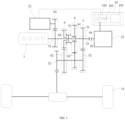
- FIG. 1 is a schematic structural diagram of a hybrid power system according to some embodiments of the present disclosure. As shown in FIG. 1 , the hybrid power system includes a gearbox, an engine 1, a first motor 21, and a second motor 22.
- the engine 1 and the first motor 21 are drivingly connected to the first input shaft 31, and the second motor 22 is drivingly connected to the second input shaft 33.
- an input gear 41 of the first gear train 4 is sleeved on the first input shaft 31, and an output gear 42 of the first gear train 4 is coaxially connected to the output shaft 32.
- the engine 1 is drivingly connected to the first input shaft 31, such that the kinetic energy of the engine 1 is output to the first input shaft 31, the first input shaft 31 is drivingly connected to the output shaft 32 via the first gear train 4, and the first synchronizer 71 is connected to the first input shaft 31.
- the first synchronizer 71 controls whether the input gear 41 of the first gear train 4 is connected to the first input shaft 31, and thus the kinetic energy output by the engine 1 is transmitted to the first gear train 4 and the output shaft 32 through the first input shaft 31 to drive the wheels 11.
- the second motor 22 is drivingly connected to the second input shaft 33, and the second input shaft 33 is drivingly connected to the output shaft 32 via the second gear train 5, such that the second motor 22 transmits power to the output shaft 32 only through the second gear train 5 to drive the wheels.
- the input gear and the output gear are directly engaged; or, at least one connecting gear is arranged between the input gear and the output gear.
- the second motor 22 is drivingly connected to the second input shaft 33, and the second input shaft 33 is drivingly connected to the output shaft 32 via the second gear train 5, such that the second motor 22 can transmit power to the output shaft 32 independently through the second gear train 5 to drive the wheels.
- FIG. 4 is a schematic structural diagram of a hybrid power system according to some embodiments of the present disclosure.
- the second speed change mechanism includes a second gear train 5, a third gear train 6, and a second synchronizer 72.
- an input gear 51 of the second gear train 5 and an input gear 61 of the third gear train 6 are coaxially connected to the second input shaft 33, and an output gear 52 of the second gear train 5 and an output gear 62 of the third gear train 6 are sleeved on the output shaft 32.
- the first input shaft 31 is coaxially spaced from the second input shaft 33, and the first synchronizer 71 is configured to cause at most one of the input gear 41 of the first gear train 4 and the input gear 51 of the second gear train 5 to be connected to the first input shaft 31.
- the first synchronizer 71 is connected to the input gear 51 of the second gear train 5
- the second synchronizer 72 is connected to the output gear 52 of the second gear train 5, and the power of the engine 1 is transmitted to the output shaft 32 through the second input shaft 33 and the second gear train 5 to drive the vehicle.
- the first motor 21 is connected to the first input shaft 31 via the fourth gear train 93, such that the power of the second motor 22 is transmitted to the first input shaft 31.
- the arrangement of the first motor 21 assists the engine 1 to drive the vehicle together so as to provide sufficient power for the vehicle.
- the first motor 21, like the engine 1 transmits power to the output shaft 32 through the first gear train 4 or the second gear train 5 by switching of the first synchronizer 71.
- the vehicle is driven in two gears.
- a power supply assembly 10 includes a battery 101 and two inverters 102, wherein the two inverters 102 are connected to the battery 101.
- the first motor 21 is connected to one of the two inverters 102, and the second motor 22 is connected to the other of the two inverters 102.
- the embodiments of the present disclosure provide a control method for the hybrid power system described above.
- the control method includes:
- the power mode of the hybrid power system includes an electric-only mode, an engine-only mode, a hybrid mode, or a power recovery mode.
- the engine 1 operates, the first motor 21 and the second motor 22 do not operate, and the first synchronizer 71 is connected to the input gear 41 of the first gear train 4 or the input gear 51 of the second gear train 5.
- the engine 1 also drives the first motor 21 to rotate, so as to cause the first motor 21 to enter a power generation state to charge the power supply assembly 10.
- FIG. 7 is a schematic diagram of the power transfer of a hybrid power system in a hybrid mode according to some embodiments of the present disclosure.
- the engine 1 drives the first motor 21 to generate electricity, and the first synchronizer 71 is not connected to the input gear 41 of the first gear train 4 and the input gear 51 of the second gear train 5, while the second motor 22 operates.
- the engine 1 and the first motor 21 operate, and the first synchronizer 71 is connected to the input gear 41 of the first gear train 4 or the input gear 51 of the second gear train 5, while the second motor 22 operates.
- the first synchronizer 71 is in the left or right position, and the engine 1, the second motor 22 and the first motor 21 jointly drive the vehicle to travel.
- the torque of the engine 1 and the first motor 21 is transmitted to the output shaft 32 through the first gear train 4 or the second gear train 5, and the torque of the second motor 22 is transmitted to the output shaft 32 through the second gear train 5, such that the mode of jointly driving the vehicle by the engine 1 and the two motors is achieved.
- FIG. 8 is a schematic diagram of the power transfer of a hybrid power system in a hybrid mode according to some embodiments of the present disclosure.
- the first gear train 4 is connected to the first input shaft 31, the torque of the engine 1 and the first motor 21 is transmitted to the wheels 11 through the first gear train 4, the output shaft 32 and the differential, and the torque of the first motor 21 is transmitted to the wheels 11 through the second gear train 5, the output shaft 32 and the differential, so as to achieve the purpose of jointly driving the vehicle to travel by the three power sources.
- the engine 1 and the first motor 21 operate, and the first synchronizer 71 is connected to the input gear 41 of the first gear train 4 or the input gear 51 of the second gear train 5, while the second motor 22 does not operate.
Landscapes
- Engineering & Computer Science (AREA)
- Mechanical Engineering (AREA)
- Chemical & Material Sciences (AREA)
- Combustion & Propulsion (AREA)
- Transportation (AREA)
- General Engineering & Computer Science (AREA)
- Structure Of Transmissions (AREA)
- Hybrid Electric Vehicles (AREA)
Abstract
Description
- The present disclosure claims priority to
Chinese Patent Application No. 202111253291.1, filed on October 27, 2021 - The present disclosure relates to the technical field of automobiles, and in particular, to a hybrid power system and a vehicle.
- Most traditional automobiles use fossil fuels (such as gasoline and diesel oil) to supply power for engines, and their exhaust gas pollutes the environment. Therefore, it is urgent to replace fossil fuels with new pollution-free energy sources (such as electric energy) to provide power for automobiles, and the automobiles equipped with hybrid power systems are the trend of development.
- In the related art, a motor of a hybrid power automobile is directly incorporated into a hydraulic automatic transmission (AT), a mechanical continuously variable transmission (CVT), or an electronic automated mechanical transmission (AMT), and the hybrid transmission system has a complex structure and low transmission efficiency.
- Embodiments of the present disclosure provide a hybrid power system and a vehicle.
- In a first aspect, a hybrid power system is provided. The hybrid power system includes: a gearbox, an engine, a first motor, and a second motor, wherein the gearbox includes a first input shaft, an output shaft, a second input shaft, a first speed change mechanism, and a second speed change mechanism, the first input shaft is connected to the output shaft via the first speed change mechanism, and the second input shaft is connected to the output shaft via the second speed change mechanism; the engine and the first motor are drivingly connected to the first input shaft; and the second motor is drivingly connected to the second input shaft.
- In some embodiments, the first speed change mechanism includes a first gear train and a first synchronizer, wherein an input gear of the first gear train is sleeved on the first input shaft, and an output gear of the first gear train is coaxially connected to the output shaft; and the first synchronizer is sleeved on the first input shaft and is configured to cause the input gear of the first gear train to be connected to the first input shaft or cause the input gear of the first gear train to be disconnected from the first input shaft.
- In some embodiments, the second speed change mechanism includes a second gear train, wherein an input gear of the second gear train is coaxially connected to the second input shaft, and an output gear of the second gear train is coaxially connected to the output shaft; and the first input shaft is coaxially spaced from the second input shaft, the input gear of the second gear train is disposed at one end of the second input shaft opposite to the first input shaft, and the first synchronizer is configured to cause at most one of the input gear of the first gear train and the input gear of the second gear train to be connected to the first input shaft.
- In some embodiments, the first speed change mechanism further includes a third gear train, wherein an input gear of the third gear train is sleeved on the first input shaft, and an output gear of the third gear train is coaxially connected to the output shaft; and the first synchronizer is disposed between the input gear of the first gear train and the input gear of the third gear train, and the first synchronizer is configured to cause at most one of the input gear of the first gear train and the input gear of the third gear train to be connected to the first input shaft.
- In some embodiments, the second speed change mechanism includes a second gear train, wherein an input gear of the second gear train is coaxially connected to the second input shaft, and an output gear of the second gear train is coaxially connected to the output shaft.
- In some embodiments, the first input shaft is coaxially spaced from the second input shaft; and the second speed change mechanism further includes a support shaft, wherein a first end of the support shaft is movably connected to a first end of the first input shaft in a circumferential direction, a second end of the first input shaft is drivingly connected to the engine, and a second end of the support shaft is coaxially connected to the second input shaft; and an input gear of the third gear train is sleeved on the support shaft.
- In some embodiments, a sleeve coaxially connected to the support shaft is arranged at the first end of the support shaft, one end of the sleeve is open, and the sleeve is opposite to the first end of the first input shaft; and a bearing is arranged in the sleeve, wherein an outer ring of the bearing is connected to an inner wall of the sleeve, and an inner ring of the bearing is sleeved on the first end of the first input shaft.
- In some embodiments, the second speed change mechanism further includes a clutch disposed between the input gear of the second gear train and the second motor.
- In some embodiments, the second speed change mechanism includes a second gear train, a third gear train, and a second synchronizer; an input gear of the second gear train and an input gear of the third gear train are both coaxially connected to the second input shaft, and an output gear of the second gear train and an output gear of the third gear train are sleeved on the output shaft; the first input shaft is coaxially spaced from the second input shaft, the first synchronizer is configured to cause at most one of the input gear of the first gear train and the input gear of the second gear train to be connected to the first input shaft; and the second synchronizer is sleeved on the output shaft and is configured to be drivingly connected to at most one of the output gear of the second gear train and the output gear of the third gear train.
- In some embodiments, the gearbox further includes a fourth gear train, wherein the first motor is coaxially connected to an input gear of the fourth gear train, and an output gear of the fourth gear train is coaxially connected to the first input shaft.
- In some embodiments, the hybrid power system further includes a power supply assembly, wherein the power supply assembly includes a battery and two inverters, the two inverters being connected to the battery, the first motor being connected to one of the two inverters, and the second motor being connected to the other of the two inverters.
- In a second aspect, a vehicle is provided. The vehicle includes the hybrid power system as described above.
- The technical solutions according to the embodiments of the present disclosure at least achieve the following beneficial effects.
- In the hybrid power system provided in the embodiments of the present disclosure, the first input shaft is connected to the output shaft of the gearbox via the first speed change mechanism, the second input shaft is connected to the output shaft of the gearbox via the second speed change mechanism, and the kinetic energy output by the engine and the two motors is transmitted to the output shaft via the two speed change mechanisms, such that the purpose of driving a vehicle to travel is achieved. Because the gearbox only uses two speed change mechanisms connected to the corresponding input shaft and output shaft, there are no other redundant structures, and the overall structure of the gearbox is simpler. In the single motor mode that only a motor needs to work alone, only the second motor needs to work, and the power of the second motor is directly transmitted to the second input shaft, such that the engine and the first motor are not directly dragged by the second input shaft to rotate, and the energy loss is avoided, thereby increasing the transmission efficiency.
- For clearer illustration of the technical solutions in the embodiments of the present disclosure, the drawings required to be used in the description of the embodiments are briefly introduced below. It is apparent that the drawings in the description below are only for some embodiments of the present disclosure, and for those of ordinary skill in the art, other drawings can be acquired according to the drawings without creative efforts.
-
FIG. 1 is a schematic structural diagram of a hybrid power system according to some embodiments of the present disclosure; -
FIG. 2 is a schematic structural diagram of a hybrid power system according to some embodiments of the present disclosure; -
FIG. 3 is a schematic structural diagram of a hybrid power system according to some embodiments of the present disclosure; -
FIG. 4 is a schematic structural diagram of a hybrid power system according to some embodiments of the present disclosure; -
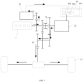
FIG. 5 is a schematic diagram of the power transfer of a hybrid power system in an electric-only mode according to some embodiments of the present disclosure; -
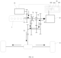
FIG. 6 is a schematic diagram of the power transfer of a hybrid power system in an engine-only mode according to some embodiments of the present disclosure; -
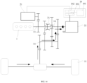
FIG. 7 is a schematic diagram of the power transfer of a hybrid power system in a hybrid mode according to some embodiments of the present disclosure; -
FIG. 8 is a schematic diagram of the power transfer of a hybrid power system in a hybrid mode according to some embodiments of the present disclosure; -
FIG. 9 is a schematic diagram of the power transfer of a hybrid power system in a hybrid mode according to some embodiments of the present disclosure; -
FIG. 10 is a schematic diagram of the power transfer of a hybrid power system in a power recovery mode according to some embodiments of the present disclosure; -
FIG. 11 is a schematic diagram of the power transfer of a hybrid power system in an electric-only mode according to some embodiments of the present disclosure; -
FIG. 12 is a schematic diagram of the power transfer of a hybrid power system in an engine-only mode according to some embodiments of the present disclosure; -
FIG. 13 is a schematic diagram of the power transfer of a hybrid power system in a hybrid mode according to some embodiments of the present disclosure; -
FIG. 14 is a schematic diagram of the power transfer of a hybrid power system in a hybrid mode according to some embodiments of the present disclosure; -
FIG. 15 is a schematic diagram of the power transfer of a hybrid power system in a hybrid mode according to some embodiments of the present disclosure; and -
FIG. 16 is a schematic diagram of the power transfer of a hybrid power system in a power recovery mode according to some embodiments of the present disclosure. - The symbols in the figures are illustrated as follows:
- A-first speed change mechanism; B-second speed change mechanism;
- 1-engine;
- 21-first motor; 22-second motor;
- 31-first input shaft; 32-output shaft; 33-second input shaft;
- 4-first gear train; 41-input gear of the first gear train; 42-output gear of the first gear train;
- 5-second gear train; 51-input gear of the second gear train; 52 -output gear of the second gear train;
- 6-third gear train; 61-input gear of the third gear train; 62-output gear of the third gear train;
- 71-first synchronizer; 72-second synchronizer;
- 91-support shaft; 92-clutch; 93-fourth gear train;
- 10-power supply assembly; 101-battery; 102-inverter;
- 11-wheel.
- For clearer descriptions of the objectives, technical solutions, and advantages of the present disclosure, the embodiments of the present disclosure are further described in detail below with reference to the accompanying drawings.
- Unless otherwise defined, technical or scientific terms used herein shall have the ordinary meaning as understood by those of ordinary skill in the art to which the present disclosure belongs. "First", "second", "third", and other similar words, as used in the specification and in the claims of the patent application of the present disclosure, do not indicate any order, quantity, or importance, but are merely defined to distinguish different components. Likewise, "a", "an" or other similar words do not indicate a limitation of quantity, but rather the presence of at least one. "Include", "comprise" or other similar words mean that the elements or objects stated before "include" or "comprise" encompass the elements or objects and equivalents thereof listed after "include" or "comprise", but do not exclude other elements or objects. "Connecting", "connected", or other similar words are not limited to physical or mechanical connections, but may include electrical connections, whether direct or indirect. "Up", "down", "left", "right", "top", "bottom", and the like are merely defined to indicate relative positional relationships. In the case that the absolute position of a described object changes, the relative position relationship may also change accordingly.
- The related art provides a hybrid power system. The system includes an engine, a motor, and a gearbox, wherein the gearbox includes an input shaft and an output shaft, and the input shaft is drivingly connected to the output shaft via at least one speed change mechanism. The engine and the motor are drivingly connected to the input shaft, such that the kinetic energy is transmitted to the output shaft via the input shaft to drive the wheels to rotate.
- However, the engine and the motor are drivingly connected to the input shaft, in the case that one of the power sources works alone, the other power source is dragged by the input shaft to rotate, thereby causing energy loss. And at least one speed change mechanism is arranged between the input shaft and the output shaft, such that the structure of the gearbox is more complex.
-
FIG. 1 is a schematic structural diagram of a hybrid power system according to some embodiments of the present disclosure. As shown inFIG. 1 , the hybrid power system includes a gearbox, anengine 1, afirst motor 21, and asecond motor 22. - As shown in
FIG. 1 , the gearbox includes afirst input shaft 31, anoutput shaft 32, asecond input shaft 33, a first speed change mechanism A, and a second speed change mechanism B, wherein thefirst input shaft 31 and theoutput shaft 32 are connected via the first speed change mechanism A, and thesecond input shaft 33 and theoutput shaft 32 are connected via the second speed change mechanism B. - As shown in
FIG. 1 , theengine 1 and thefirst motor 21 are drivingly connected to thefirst input shaft 31, and thesecond motor 22 is drivingly connected to thesecond input shaft 33. - In the hybrid power system provided in the embodiments of the present disclosure, the first input shaft is connected to the output shaft of the gearbox via the first speed change mechanism, the second input shaft is connected to the output shaft of the gearbox via the second speed change mechanism, and the kinetic energy output by the engine and the two motors is transmitted to the output shaft through the two speed change mechanisms, such that the purpose of driving a vehicle to travel is achieved. Because the gearbox only uses two speed change mechanisms connected to the corresponding input shaft and output shaft, there is no other redundant structures, and the overall structure of the gearbox is simpler. In the single motor mode that only a motor needs to work alone, only the second motor needs to work, and the power of the second motor is directly transmitted to the second input shaft, such that the engine and the first motor are not directly dragged by the second input shaft to rotate, and the energy loss is avoided, thereby increasing the transmission efficiency.
-
FIG. 2 is a schematic structural diagram of a hybrid power system according to some embodiments of the present disclosure. As shown inFIG. 2 , the first speed change mechanism includes afirst gear train 4 and afirst synchronizer 71. - As shown in
FIG. 2 , an input gear 41 of thefirst gear train 4 is sleeved on thefirst input shaft 31, and anoutput gear 42 of thefirst gear train 4 is coaxially connected to theoutput shaft 32. - The
first synchronizer 71 is sleeved on thefirst input shaft 31, and thefirst synchronizer 71 is configured to cause the input gear 41 of thefirst gear train 4 to be connected to thefirst input shaft 31 or cause the input gear 41 of thefirst gear train 4 to be disconnected from thefirst input shaft 31. - In the above implementations, the
engine 1 is drivingly connected to thefirst input shaft 31, such that the kinetic energy of theengine 1 is output to thefirst input shaft 31, thefirst input shaft 31 is drivingly connected to theoutput shaft 32 via thefirst gear train 4, and thefirst synchronizer 71 is connected to thefirst input shaft 31. Thefirst synchronizer 71 controls whether the input gear 41 of thefirst gear train 4 is connected to thefirst input shaft 31, and thus the kinetic energy output by theengine 1 is transmitted to thefirst gear train 4 and theoutput shaft 32 through thefirst input shaft 31 to drive thewheels 11. - In the case that the hybrid power system operates, the kinetic energy of the engine is transmitted to the output shaft through the first input shaft and the first gear train, and the kinetic energy of the second motor is transmitted to the output shaft through the second input shaft. In the process, the engine and the second motor do not drag the two input shafts to rotate simultaneously, such that the power source is prevented from being directly dragged to rotate, and the energy loss is avoided.
- Meanwhile, the input gear 41 of the
first gear train 4 is controlled to be disconnected from thefirst input shaft 31 by thefirst synchronizer 71. In this way, even if the power is transmitted to thefirst gear train 4 through theoutput shaft 32, the power is not transmitted to thefirst input shaft 31 continuously, that is, thefirst input shaft 31 is not indirectly dragged to rotate, and thus the engine is prevented from being dragged to rotate. - In the embodiments of the present disclosure, the
first gear train 4 at least includes an input gear and an output gear, and the input gear is drivingly connected to the output gear, such that the power is transmitted to the output gear through the input gear. - In some embodiments, the input gear and the output gear of the
first gear train 4 are directly engaged to achieve transmission connection between the input gear and the output gear. At least one connecting gear is further arranged between the input gear and the output gear. For example, in the case that only one connecting gear is arranged, the connecting gear is engaged with the input gear and the output gear to achieve transmission connection between the input gear and the output gear. - It should be noted that the specific quantity of gears to be arranged in the
first gear train 4 is determined according to actual demands. Because the quantity of gears arranged in the gear train affects the transmission ratio of the gear train, the quantity of gears in the gear train is adjusted according to the power demand of a vehicle. - In some embodiments, as shown in
FIG. 2 , the second speed change mechanism includes asecond gear train 5, wherein aninput gear 51 of thesecond gear train 5 is coaxially connected to thesecond input shaft 33, and anoutput gear 52 of thesecond gear train 5 is coaxially connected to theoutput shaft 32. - The
second motor 22 is drivingly connected to thesecond input shaft 33, and thesecond input shaft 33 is drivingly connected to theoutput shaft 32 via thesecond gear train 5, such that thesecond motor 22 transmits power to theoutput shaft 32 only through thesecond gear train 5 to drive the wheels. - As shown in
FIG. 2 , thefirst input shaft 31 is coaxially spaced from thesecond input shaft 33, and thefirst synchronizer 71 is configured to cause at most one of the input gear 41 of thefirst gear train 4 and theinput gear 51 of thesecond gear train 5 to be connected to thefirst input shaft 31. - The
first synchronizer 71 is disposed between the input gear 41 of thefirst gear train 4 and theinput gear 51 of thesecond gear train 5. Thefirst synchronizer 71 is axially movable on thefirst input shaft 31, such that thefirst gear train 4 is drivingly connected to thefirst input shaft 31 in the case that thefirst synchronizer 71 approaches thefirst gear train 4 and is engaged with the input gear 41 of thefirst gear train 4. - In some embodiments, as shown in
FIG. 2 , theinput gear 51 of thesecond gear train 5 is disposed at one end of thesecond input shaft 33 opposite to thefirst input shaft 31, and one end of thefirst input shaft 31 opposite to thesecond input shaft 33 is movably inserted into theinput gear 51 of thesecond gear train 5. - Because the
second input shaft 33 is coaxially spaced from thefirst input shaft 31, and one end of thefirst input shaft 31 opposite to thesecond input shaft 33 is movably inserted into theinput gear 51 of thesecond gear train 5, thefirst synchronizer 71 is also engaged with theinput gear 51 of thesecond gear train 5 in the case that thefirst synchronizer 71 approaches thesecond gear train 5, and thus thesecond gear train 5 is drivingly connected to thefirst input shaft 31. Thefirst synchronizer 71 can also be disconnected from both the input gear 41 of thefirst gear train 4 and theinput gear 51 of thesecond gear train 5, that is, thefirst input shaft 31 and theoutput shaft 32 are disconnected. - In the case that the
first synchronizer 71 is engaged with thefirst gear train 4, the power of theengine 1 is transmitted to theoutput shaft 32 through thefirst gear train 4. Because thesecond motor 22 is drivingly connected to theinput gear 51 of thesecond gear train 5 directly, there is no need to connect theinput gear 51 via thefirst synchronizer 71. In this way, thesecond motor 22 is controlled to work, such that the power of thesecond motor 22 is transmitted to theoutput shaft 32 through thesecond gear train 5. Compared with the related art, in the hybrid power system, theengine 1 and thesecond motor 22 transmit power to theoutput shaft 32 through two gear trains, so that another gear can be used to drive the vehicle, improving the use efficiency of the gear trains and realizing a multi-gear driving mode of the hybrid power system. - In the embodiments of the present disclosure, the
second gear train 5 at least includes an input gear and an output gear, and the input gear is drivingly connected to the output gear, such that the power is transmitted to the output gear through the input gear. - In some embodiments, in the
second gear train 5, the input gear and the output gear are directly engaged; or, at least one connecting gear is arranged between the input gear and the output gear. - It should be noted that the specific quantity of gears to be arranged in the
second gear train 5 is determined based on actual demands. -
FIG. 3 is a schematic structural diagram of a hybrid power system according to some embodiments of the present disclosure. As shown inFIG. 3 , the first speed change mechanism further includes athird gear train 6, wherein aninput gear 61 of thethird gear train 6 is sleeved on thefirst input shaft 31, and anoutput gear 62 of thethird gear train 6 is coaxially connected to theoutput shaft 32. - As shown in
FIG. 3 , thefirst synchronizer 71 is disposed between the input gear 41 of thefirst gear train 4 and theinput gear 61 of thethird gear train 6, and thefirst synchronizer 71 is configured to cause at most one of the input gear 41 of thefirst gear train 4 and theinput gear 61 of thethird gear train 6 to be connected to thefirst input shaft 31. - In the above implementations, the
first gear train 4 and thethird gear train 6 are connected to thefirst input shaft 31 and theoutput shaft 32 simultaneously, and thefirst synchronizer 71 is disposed between thefirst gear train 4 and thethird gear train 6. In this way, in the case that thefirst synchronizer 71 moves to another place and is engaged with the input gear 41 of thefirst gear train 4, thefirst gear train 4 is connected to thefirst input shaft 31, such that the power of theengine 1 is transmitted to theoutput shaft 32 through thefirst gear train 4. Meanwhile, in the case that thefirst synchronizer 71 moves to another place and is engaged with theinput gear 61 of thethird gear train 6, thethird gear train 6 is connected to thefirst input shaft 31, such that the power of theengine 1 is transmitted to theoutput shaft 32 through thethird gear train 6, and theengine 1 drives the vehicle in two gears. - In some embodiments, as shown in
FIG. 3 , the second speed change mechanism includes asecond gear train 5, wherein aninput gear 51 of thesecond gear train 5 is coaxially connected to thesecond input shaft 33, and anoutput gear 52 of thesecond gear train 5 is coaxially connected to theoutput shaft 32. - The
second motor 22 is drivingly connected to thesecond input shaft 33, and thesecond input shaft 33 is drivingly connected to theoutput shaft 32 via thesecond gear train 5, such that thesecond motor 22 can transmit power to theoutput shaft 32 independently through thesecond gear train 5 to drive the wheels. - In some embodiments, as shown in
FIG. 3 , thefirst input shaft 31 is coaxially spaced from thesecond input shaft 33, and the second speed change mechanism B further includes asupport shaft 91, wherein a first end of thesupport shaft 91 is movably connected to a first end of thefirst input shaft 31 in the circumferential direction, a second end of thefirst input shaft 31 is drivingly connected to theengine 1, and a second end of thesupport shaft 91 is coaxially connected to thesecond input shaft 33; and theinput gear 61 of thethird gear train 6 is sleeved on thesupport shaft 91. - Exemplarily, as shown in
FIG. 3 , a sleeve coaxially connected to thesupport shaft 91 is arranged at the first end of thesupport shaft 91, one end of the sleeve is open, and one end of the sleeve is opposite to the first end of thefirst input shaft 31. During assembly, the first end of thefirst input shaft 31 is coaxially inserted into the sleeve of thesupport shaft 91 to achieve the circumferential movable connection between thefirst input shaft 31 and thesupport shaft 91. - In some embodiments, a bearing is disposed in the sleeve, an outer ring of the bearing is connected to an inner wall of the sleeve, and an inner ring of the bearing is configured to be sleeved on the
first input shaft 31, such that thefirst input shaft 31 rotates more stably in the sleeve, and the connection stability between thefirst input shaft 31 and thesupport shaft 91 is improved. - In the above implementations, the
support shaft 91 is arranged, in the case that thesupport shaft 91 is connected to thefirst input shaft 31, thefirst input shaft 31 and thesupport shaft 91 form a whole portion, and both ends of the whole portion are supported by theengine 1 and thefirst motor 21 respectively. Therefore, the first end of thefirst input shaft 31 is prevented from being additionally provided with a supporting structure to support thefirst input shaft 31, such that the cost is saved, the axial size of the hybrid power system is reduced, and the hybrid power system is more compact and lightweight. - Meanwhile, the connection position of the
first input shaft 31 and thesupport shaft 91 is in an inner hole of theinput gear 61 of thethird gear train 6, such that thefirst input shaft 31 and thesupport shaft 91 are not easy to separate and fall off upon being assembled. Meanwhile, the sleeve is arranged in the inner hole of theinput gear 61 of thethird gear train 6, which avoids occupying excessive internal space of the vehicle and makes the structure of the hybrid power system more compact. - In the embodiments of the present disclosure, the
third gear train 6 at least includes an input gear and an output gear, and the input gear is drivingly connected to the output gear, such that the power is transmitted to the output gear through the input gear. - In some embodiments, in the
third gear train 6, the input gear and the output gear are directly engaged; or, at least one connecting gear is arranged between the input gear and the output gear. - It should be noted that the specific quantity of gears to be arranged in the
third gear train 6 is determined according to actual demands. - In some embodiments, as shown in
FIG. 3 , the second speed change mechanism further includes a clutch 92, wherein the clutch 92 is disposed between theinput gear 51 of thesecond gear train 5 and thesecond motor 22. - The arrangement of the clutch 92 between the
second motor 22 and theinput gear 51 of thesecond gear train 5 interrupts the power transmission path therebetween. In the case that only theengine 1 needs to work, the power of theengine 1 is not transmitted to thesecond motor 22 through thesecond gear train 5, and thesecond motor 22 is dragged to rotate, and the power loss is avoided. -
FIG. 4 is a schematic structural diagram of a hybrid power system according to some embodiments of the present disclosure. As shown inFIG. 4 , the second speed change mechanism includes asecond gear train 5, athird gear train 6, and a second synchronizer 72. - As shown in
FIG. 4 , aninput gear 51 of thesecond gear train 5 and aninput gear 61 of thethird gear train 6 are coaxially connected to thesecond input shaft 33, and anoutput gear 52 of thesecond gear train 5 and anoutput gear 62 of thethird gear train 6 are sleeved on theoutput shaft 32. - The
first input shaft 31 is coaxially spaced from thesecond input shaft 33, and thefirst synchronizer 71 is configured to cause at most one of the input gear 41 of thefirst gear train 4 and theinput gear 51 of thesecond gear train 5 to be connected to thefirst input shaft 31. - As shown in
FIG. 4 , the second synchronizer 72 is sleeved on theoutput shaft 32, and the second synchronizer 72 is configured to be drivingly connected to at most one of theoutput gear 52 of thesecond gear train 5 and theoutput gear 62 of thethird gear train 6. - In the above implementations, the
first synchronizer 71 is connected to the input gear 41 of thefirst gear train 4 or theinput gear 51 of thesecond gear train 5, such that the kinetic energy output by theengine 1 is transmitted to theoutput shaft 32 through thefirst gear train 4 and thethird gear train 5, and thus theengine 1 drives the vehicle in two gears. - The
input gear 51 of thesecond gear train 5 is coaxially connected to thesecond input shaft 33, in the case that thefirst synchronizer 71 is connected to theinput gear 51 of thesecond gear train 5, thefirst input shaft 31 is drivingly connected to thesecond input shaft 33. That is, the power of theengine 1 is also transmitted to thesecond input shaft 33, and the power of theengine 1 is transmitted to theoutput shaft 32 through thethird gear train 6 in addition to the power of theengine 1 being transmitted to theoutput shaft 32 through thesecond gear train 5, such that theengine 1 is additionally provided with a gear, and theengine 1 drives the vehicle in three gears. - Exemplarily, in the case that the
engine 1 drives the vehicle in the first gear, thefirst synchronizer 71 is connected to the input gear 41 of thefirst gear train 4, and the power of theengine 1 is transmitted to theoutput shaft 32 through thefirst gear train 4 to drive the vehicle. - Exemplarily, in the case that the
engine 1 drives the vehicle in the second gear, thefirst synchronizer 71 is connected to theinput gear 51 of thesecond gear train 5, and the second synchronizer 72 is connected to theoutput gear 52 of thesecond gear train 5, and the power of theengine 1 is transmitted to theoutput shaft 32 through thesecond input shaft 33 and thesecond gear train 5 to drive the vehicle. - Exemplarily, in the case that the
engine 1 drives the vehicle in the third gear, thefirst synchronizer 71 is connected to theinput gear 51 of thesecond gear train 5, and the second synchronizer 72 is connected to theoutput gear 62 of thethird gear train 6, and the power of theengine 1 is transmitted to theoutput shaft 32 through thesecond input shaft 33 and thethird gear train 6 to drive the vehicle. - In some embodiments, as shown in
FIGS. 2 and3 , the hybrid power system further includes afourth gear train 93, wherein thefirst motor 21 is coaxially connected to an input gear of thefourth gear train 93, an output gear of thefourth gear train 93 is coaxially connected to thefirst input shaft 31, and the input gear of thefourth gear train 93 is disposed between theengine 1 and the input gear 41 of thefirst gear train 4. - The
first motor 21 is connected to thefirst input shaft 31 via thefourth gear train 93, such that the power of thesecond motor 22 is transmitted to thefirst input shaft 31. The arrangement of thefirst motor 21 assists theengine 1 to drive the vehicle together so as to provide sufficient power for the vehicle. - Meanwhile, the
first motor 21, like theengine 1, transmits power to theoutput shaft 32 through thefirst gear train 4 or thesecond gear train 5 by switching of thefirst synchronizer 71. Thus, the vehicle is driven in two gears. - In the embodiments of the present disclosure, the
fourth gear train 93 at least includes an input gear and an output gear, and the input gear is drivingly connected to the output gear, such that the power is transmitted to the output gear through the input gear. - In some embodiments, in the
fourth gear train 93, the input gear and the output gear are directly engaged; or, at least one connecting gear is arranged between the input gear and the output gear. - It should be noted that the specific quantity of gears to be arranged in the
fourth gear train 93 is determined based on actual demands. - In some embodiments, as shown in
FIGS. 2 and3 , apower supply assembly 10 includes abattery 101 and twoinverters 102, wherein the twoinverters 102 are connected to thebattery 101. Thefirst motor 21 is connected to one of the twoinverters 102, and thesecond motor 22 is connected to the other of the twoinverters 102. - The two
inverters 102 are arranged, one of the two inverters is configured to cause thebattery 101 to be connected to thefirst motor 21, and the other inverter is configured to cause thebattery 101 to be connected to thesecond motor 22. Thebattery 101 is arechargeable battery 101, and theinverter 102 is arranged on an output circuit of thebattery 101 and is configured to convert a direct current output by thebattery 101 into a three-phase alternating current to drive thefirst motor 21 or thesecond motor 22. - The embodiments of the present disclosure provide a control method for the hybrid power system described above. The control method includes:
- controlling a first speed change mechanism to cause a first input shaft to be connected to an output shaft, controlling a second speed change mechanism to cause a second input shaft to be disconnected from the output shaft, and controlling at least one of an engine and a first motor to rotate; or
- controlling the first speed change mechanism to cause the first input shaft to be disconnected from the output shaft, controlling the second speed change mechanism to cause the second input shaft to be connected to the output shaft, and controlling the second motor to rotate.
- In this way, the kinetic energy output by the engine and the two motors is transmitted to the output shaft through the two speed change mechanisms, such that the purpose of driving a vehicle to travel is achieved. In the single motor mode that only a motor needs to work, the two speed change mechanisms are controlled to achieve the purpose of working only by the second motor, and the power of the second motor is directly transmitted to the second input shaft, thus the engine and the first motor are not directly dragged by the second input shaft to rotate, and the energy loss is avoided, thereby increasing the transmission efficiency.
- In some embodiments, the hybrid power system also controls the operation of the power source of the vehicle based on the power mode. The specific control method includes determining a power mode; and controlling the working states of the engine, the first motor and the second motor based on the power mode.
- In the embodiments of the present disclosure, the power mode of the hybrid power system includes an electric-only mode, an engine-only mode, a hybrid mode, or a power recovery mode.
- In the hybrid power system shown in
FIG. 2 , the engine, the first motor, the second motor and the first synchronizer operate in the following working states in different power modes. -
FIG. 5 is a schematic diagram of the power transfer of a hybrid power system in an electric-only mode according to some embodiments of the present disclosure. As shown inFIG. 5 , in the case that the power mode of the hybrid power system is an electric-only mode, theengine 1 and thefirst motor 21 do not operate, and thefirst synchronizer 71 is not connected to the input gear 41 of thefirst gear train 4 and theinput gear 51 of thesecond gear train 5, while thesecond motor 22 operates. - In this way, the
engine 1 and thefirst motor 21 do not operate, thefirst synchronizer 71 is in the neutral position, and the vehicle is driven to travel by thesecond motor 22. Thepower supply assembly 10 discharges, the direct current is converted into a three-phase alternating current through theinverter 102 to drive the output shaft of thesecond motor 22 to rotate, thesecond motor 22 converts the electric energy into the mechanical energy, and the mechanical energy is transmitted to thewheels 11 through thesecond gear train 5, theoutput shaft 32 and the differential, such that the mode of driving the vehicle to travel by thesecond motor 22 alone is achieved. - In some embodiments, the vehicle is also driven in reverse gear by the
second motor 22 in the electric-only mode. During reverse, theengine 1 and thefirst motor 21 do not operate, and thesecond motor 22 anticlockwise rotates to achieve reverse. In this mode, the energy transfer path is seen inFIG. 4 . - In some embodiments, in the case that the power mode of the hybrid power system is an engine-only mode, the
engine 1 operates, thefirst motor 21 and thesecond motor 22 do not operate, and thefirst synchronizer 71 is connected to the input gear 41 of thefirst gear train 4 or theinput gear 51 of thesecond gear train 5. - At the moment, the
first synchronizer 71 is in the left or right position, and the vehicle is driven to travel by theengine 1. The torque of theengine 1 is transmitted to theoutput shaft 32 through thefirst gear train 4 or thesecond gear train 5, and the mode of driving the vehicle to travel in two gears by theengine 1 is achieved. - Taking the
first synchronizer 71 moving to the left position as an example,FIG. 6 is a schematic diagram of the power transfer of a hybrid power system in an engine-only mode according to some embodiments of the present disclosure. As shown inFIG. 6 , thefirst gear train 4 is connected to thefirst input shaft 31, and the torque of theengine 1 is transmitted to thewheels 11 through thefirst gear train 4, theoutput shaft 32 and the differential, such that the mode of driving the vehicle to travel by theengine 1 alone is achieved. - Exemplarily, at the moment, the
engine 1 also drives thefirst motor 21 to rotate, so as to cause thefirst motor 21 to enter a power generation state to charge thepower supply assembly 10. -
FIG. 7 is a schematic diagram of the power transfer of a hybrid power system in a hybrid mode according to some embodiments of the present disclosure. As shown inFIG. 7 , in the case that the power mode of the hybrid power system is a hybrid mode, theengine 1 drives thefirst motor 21 to generate electricity, and thefirst synchronizer 71 is not connected to the input gear 41 of thefirst gear train 4 and theinput gear 51 of thesecond gear train 5, while thesecond motor 22 operates. - In this way, the
first synchronizer 71 is in a neutral position, theengine 1 operates in a high-efficiency area to drive thefirst motor 21 to generate electricity, the generated electricity is supplied to thesecond motor 22 to drive the vehicle to travel, and excess electricity is stored in thepower supply assembly 10. In the case that the power generation amount is insufficient and is supplemented by thepower supply assembly 10, thefirst motor 21 and thepower supply assembly 10 jointly meet the electric quantity demand of thesecond motor 22. As shown inFIG. 7 , the power output by thesecond motor 22 is transmitted to thewheels 11 through thesecond gear train 5, theoutput shaft 32 and the differential to drive the vehicle to travel. - In some embodiments, in the case that the power mode of the hybrid power system is a hybrid mode, the
engine 1 and thefirst motor 21 operate, and thefirst synchronizer 71 is connected to the input gear 41 of thefirst gear train 4 or theinput gear 51 of thesecond gear train 5, while thesecond motor 22 operates. - In this way, the
first synchronizer 71 is in the left or right position, and theengine 1, thesecond motor 22 and thefirst motor 21 jointly drive the vehicle to travel. The torque of theengine 1 and thefirst motor 21 is transmitted to theoutput shaft 32 through thefirst gear train 4 or thesecond gear train 5, and the torque of thesecond motor 22 is transmitted to theoutput shaft 32 through thesecond gear train 5, such that the mode of jointly driving the vehicle by theengine 1 and the two motors is achieved. - Taking the
first synchronizer 71 moving to the left position as an example,FIG. 8 is a schematic diagram of the power transfer of a hybrid power system in a hybrid mode according to some embodiments of the present disclosure. As shown inFIG. 8 , thefirst gear train 4 is connected to thefirst input shaft 31, the torque of theengine 1 and thefirst motor 21 is transmitted to thewheels 11 through thefirst gear train 4, theoutput shaft 32 and the differential, and the torque of thefirst motor 21 is transmitted to thewheels 11 through thesecond gear train 5, theoutput shaft 32 and the differential, so as to achieve the purpose of jointly driving the vehicle to travel by the three power sources. - In this mode, the power of the
engine 1 and thefirst motor 21 is transmitted out of theoutput shaft 32 through thefirst gear train 4. The power of thesecond motor 22 is transmitted to theoutput shaft 32 through thesecond gear train 5. Compared with the related art, theengine 1, thefirst motor 21 and thesecond motor 22 transmit power to theoutput shaft 32 through two gear trains, so another gear is used to drive the vehicle, improving the use efficiency of the gear trains, and realizing a multi-gear driving mode of the hybrid power system. - In some embodiments, in the case that the power mode of the hybrid power system is a hybrid mode, the
engine 1 and thefirst motor 21 operate, and thefirst synchronizer 71 is connected to the input gear 41 of thefirst gear train 4 or theinput gear 51 of thesecond gear train 5, while thesecond motor 22 does not operate. - In this way, the
first synchronizer 71 is in the left or right position, and the vehicle is driven to travel by theengine 1 and thefirst motor 21 together. Thepower supply assembly 10 discharges, the direct current is converted into a three-phase alternating current through theinverter 102 to drive thefirst motor 21 to rotate, and thefirst motor 21 is in a power generation or electric state according to the vehicle speed and torque requirements. The torque of theengine 1 and thefirst motor 21 is transmitted to thewheels 11 through thefirst gear train 4 or thesecond gear train 5, theoutput shaft 32 and the differential, and the mode of jointly driving the vehicle to travel in two gears by two power sources is achieved. - Taking the
first synchronizer 71 moving to the left position as an example,FIG. 9 is a schematic diagram of the power transfer of a hybrid power system in a hybrid mode according to some embodiments of the present disclosure. As shown inFIG. 9 , theengine 1 and thefirst motor 21 operate, while thesecond motor 22 does not operate, the vehicle is driven to start and travel by the power supplied from theengine 1, and thefirst motor 21 operates in a power generation or electric mode according to the vehicle speed and torque requirements. -
FIG. 10 is a schematic diagram of the power transfer of a hybrid power system in a power recovery mode according to some embodiments of the present disclosure. As shown inFIG. 10 , in the case that the power mode of the hybrid power system is an energy recovery mode, theengine 1 and thefirst motor 21 do not operate, and thefirst synchronizer 71 is not connected to the input gear 41 of thefirst gear train 4 and theinput gear 51 of thesecond gear train 5, while thesecond motor 22 generates electricity. - In this mode, the vehicle is in a coasting or braking condition, the
wheels 11 provide reverse torque, and a part of kinetic energy of the vehicle is transmitted to thesecond motor 22 through the differential, theoutput shaft 32 and thesecond gear train 5 to be converted into electric energy, which is stored in thepower supply assembly 10 for later use, so as to achieve the energy recovery function of thesecond motor 22. - In the hybrid power system shown in
FIG. 3 , the engine, the first motor, the second motor and the first synchronizer operate in the following working states in different power modes. -
FIG. 11 is a schematic diagram of the power transfer of a hybrid power system in an electric-only mode according to some embodiments of the present disclosure. As shown inFIG. 11 , in the case that the power mode of the hybrid power system is an electric-only mode, theengine 1 and thefirst motor 21 do not operate, and thefirst synchronizer 71 is not connected to the input gear 41 of thefirst gear train 4 and theinput gear 51 of thesecond gear train 5, while thesecond motor 22 operates, and the clutch 92 is engaged. - In this way, the
engine 1 and thefirst motor 21 do not operate, thefirst synchronizer 71 is in the neutral position, the clutch 92 is engaged, and the vehicle is driven to travel by thesecond motor 22. Thepower supply assembly 10 discharges, the direct current is converted into a three-phase alternating current through theinverter 102 to drive the output shaft of thesecond motor 22 to rotate, thesecond motor 22 converts the electric energy into the mechanical energy, and the mechanical energy is transmitted to thewheels 11 through the clutch 92, thethird gear train 6, theoutput shaft 32 and the differential, such that the mode of driving the vehicle to travel by thesecond motor 22 alone is achieved. - In some embodiments, the vehicle is also driven in reverse gear by the
second motor 22 in the electric-only mode. During reverse, theengine 1 and thefirst motor 21 do not operate, and thesecond motor 22 anticlockwise rotates to achieve reverse. In this mode, the energy transfer path is seen inFIG. 10 . - In some embodiments, in the case that the power mode of the hybrid power system is an engine-only mode, the
engine 1 operates, thesecond motor 22 and thefirst motor 21 do not operate, thefirst synchronizer 71 is connected to the input gear 41 of thefirst gear train 4 or theinput gear 51 of thesecond gear train 5, and the clutch 92 is disengaged. - In this way, the
first synchronizer 71 is in the left or right position, the clutch 92 is disengaged, and the vehicle is driven to travel by theengine 1. The torque of theengine 1 is transmitted to theoutput shaft 32 through thefirst gear train 4 or thesecond gear train 5, and the mode of driving the vehicle to travel in two gears by theengine 1 is achieved. - Taking the
first synchronizer 71 moving to the left position as an example,FIG. 12 is a schematic diagram of the power transfer of a hybrid power system in an engine-only mode according to some embodiments of the present disclosure. As shown inFIG. 12 , thefirst gear train 4 is connected to thefirst input shaft 31, and the torque of theengine 1 is transmitted to thewheels 11 through thefirst gear train 4, theoutput shaft 32 and the differential, such that the mode of driving the vehicle to travel by theengine 1 alone is achieved. - Exemplarily, at the moment, the
engine 1 also drives thefirst motor 21 to rotate, so as to cause thefirst motor 21 to enter a power generation state to charge thepower supply assembly 10. -
FIG. 13 is a schematic diagram of the power transfer of a hybrid power system in a hybrid mode according to some embodiments of the present disclosure. As shown inFIG. 13 , in the case that the power mode of the hybrid power system is a hybrid mode, theengine 1 drives thefirst motor 21 to generate electricity, and thefirst synchronizer 71 is not connected to the input gear 41 of thefirst gear train 4 and theinput gear 51 of thesecond gear train 5, while thesecond motor 22 operates, and the clutch 92 is engaged. - In this way, the
first synchronizer 71 is in a neutral position, the clutch 92 is engaged, theengine 1 operates in a high-efficiency area to drive thefirst motor 21 to generate electricity, the generated electricity is supplied to thesecond motor 22 to drive the vehicle to travel, and excess electricity is stored in thepower supply assembly 10. In the case that the power generation amount is insufficient and is supplemented by thepower supply assembly 10, thefirst motor 21 and thepower supply assembly 10 jointly meet the electric quantity demand of thesecond motor 22. As shown inFIG. 12 , the power output by thesecond motor 22 is transmitted to thewheels 11 through the clutch 92, thethird gear train 6, theoutput shaft 32 and the differential to drive the vehicle to travel. - In some embodiments, in the case that the power mode of the hybrid power system is a hybrid mode, the
engine 1 and thefirst motor 21 operate, and thefirst synchronizer 71 is connected to the input gear 41 of thefirst gear train 4 or theinput gear 51 of thesecond gear train 5, while thesecond motor 22 operates, and the clutch 92 is engaged. - In this way, the
first synchronizer 71 is in the left or right position, the clutch 92 is engaged, and the vehicle is driven to travel by theengine 1, thesecond motor 22 and thefirst motor 21 together. The torque of theengine 1 and thefirst motor 21 is transmitted to theoutput shaft 32 through thefirst gear train 4 or thesecond gear train 5, the torque of thesecond motor 22 is transmitted to theoutput shaft 32 through the clutch 92 and thethird gear train 6, and the mode of driving the vehicle to travel by theengine 1 and the two motors together is achieved. - Taking the
first synchronizer 71 moving to the left position as an example,FIG. 14 is a schematic diagram of the power transfer of a hybrid power system in a hybrid mode according to some embodiments of the present disclosure. As shown inFIG. 14 , thefirst gear train 4 is connected to thefirst input shaft 31, at the moment, the torque of theengine 1 and thefirst motor 21 is transmitted to thewheels 11 through thefirst gear train 4, theoutput shaft 32 and the differential, and the torque of thefirst motor 21 is transmitted to thewheels 11 through the clutch 92, thethird gear train 6, theoutput shaft 32 and the differential, so as to achieve the purpose of jointly driving the vehicle to travel by the three power sources. - In this mode, the power of the
engine 1 and thefirst motor 21 is transmitted out of theoutput shaft 32 through thefirst gear train 4, and the power of thesecond motor 22 is transmitted to theoutput shaft 32 through thethird gear train 6. Compared with the related art, theengine 1, thefirst motor 21 and thesecond motor 22 transmit power to theoutput shaft 32 through two gear trains, improving the use efficiency of the gear trains, and realizing a multi-gear driving mode of the hybrid power system. - In some embodiments, in the case that the power mode of the hybrid power system is the hybrid mode, the
engine 1 and thefirst motor 21 operate, and thefirst synchronizer 71 is connected to the input gear 41 of thefirst gear train 4 or theinput gear 51 of thesecond gear train 5, while thesecond motor 22 does not operate, and the clutch 92 is disengaged. - In this way, the
first synchronizer 71 is in the left or right position, and the vehicle is driven to travel by theengine 1 and thefirst motor 21 together. Thepower supply assembly 10 discharges, the direct current is converted into a three-phase alternating current through theinverter 102 to drive thefirst motor 21 to rotate, and thefirst motor 21 is in a power generation or electric state according to the vehicle speed and torque requirements. The torque of theengine 1 and thefirst motor 21 is transmitted to thewheels 11 through thefirst gear train 4 or thesecond gear train 5, theoutput shaft 32 and the differential, and the mode of jointly driving the vehicle to travel in two gears by two power sources is achieved. - Taking the
first synchronizer 71 moving to the left position as an example,FIG. 15 is a schematic diagram of the power transfer of a hybrid power system in a hybrid mode according to some embodiments of the present disclosure. As shown inFIG. 15 , theengine 1 and thefirst motor 21 operate, while thesecond motor 22 does not operate, the vehicle is driven to start and travel by the power supplied from theengine 1, and thefirst motor 21 operates in a power generation or electric mode according to the vehicle speed and torque requirements. -
FIG. 16 is a schematic diagram of the power transfer of a hybrid power system in a power recovery mode according to some embodiments of the present disclosure. As shown inFIG. 16 , in the case that the power mode of the hybrid power system is an energy recovery mode, theengine 1 and thefirst motor 21 do not operate, and thefirst synchronizer 71 is not connected to the input gear 41 of thefirst gear train 4 and theinput gear 51 of thesecond gear train 5, while thesecond motor 22 generates electricity, and the clutch 92 is engaged. - In this mode, in the case that the vehicle is in a coasting or braking condition, the
wheels 11 provide reverse torque, and a part of kinetic energy of the vehicle is transmitted to thesecond motor 22 through the differential, theoutput shaft 32, thethird gear train 6 and the clutch 92 to be converted into electric energy, which is stored in thepower supply assembly 10 for later use, so as to achieve the energy recovery function of thesecond motor 22. - The above description does not limit the present disclosure in any way. Although the present disclosure has been described as above through the embodiments, they are not intended to limit the present disclosure. Those skilled in the art are able to make some changes or modifications to the above disclosed technical contents to give equivalent embodiments of equivalent changes without departing from the scope of the present disclosure. However, any simple alterations, equivalent changes and modifications made, without departing from the contents of the technical solutions of the present disclosure, on the above embodiments based on the technical essence of present disclosure shall fall within the scope of the technical solutions of the present disclosure.
Claims (12)
- A hybrid power system, comprising: a gearbox, an engine (1), a first motor (21), and a second motor (22); whereinthe gearbox comprises a first input shaft (31), an output shaft (32), a second input shaft (33), a first speed change mechanism, and a second speed change mechanism, wherein the first input shaft (31) is connected to the output shaft (32) via the first speed change mechanism, and the second input shaft (33) is connected to the output shaft (32) via the second speed change mechanism;the engine (1) and the first motor (21) are drivingly connected to the first input shaft (31); andthe second motor (22) is drivingly connected to the second input shaft (33).
- The hybrid power system according to claim 1, wherein the first speed change mechanism comprises a first gear train (4) and a first synchronizer (71); whereinan input gear of the first gear train (4) is sleeved on the first input shaft (31), and an output gear of the first gear train (4) is coaxially connected to the output shaft (32); andthe first synchronizer (71) is sleeved on the first input shaft (31), and the first synchronizer (71) is configured to cause the input gear of the first gear train (4) to be connected to the first input shaft (31) or cause the input gear of the first gear train (4) to be disconnected from the first input shaft (31).
- The hybrid power system according to claim 2, wherein the second speed change mechanism comprises a second gear train (5), wherein an input gear of the second gear train (5) is coaxially connected to the second input shaft (33), and an output gear of the second gear train (5) is coaxially connected to the output shaft (32); and
the first input shaft (31) is coaxially spaced from the second input shaft (33), the input gear of the second gear train (5) is disposed at one end of the second input shaft (33) opposite to the first input shaft (31), and the first synchronizer (71) is configured to cause at most one of the input gear of the first gear train (4) and the input gear of the second gear train (5) to be connected to the first input shaft (31). - The hybrid power system according to claim 2, wherein the first speed change mechanism further comprises a third gear train (6), wherein an input gear of the third gear train (6) is sleeved on the first input shaft (31), and an output gear of the third gear train (6) is coaxially connected to the output shaft (32); and
the first synchronizer (71) is disposed between the input gear of the first gear train (4) and the input gear of the third gear train (6), and the first synchronizer (71) is configured to cause at most one of the input gear of the first gear train (4) and the input gear of the third gear train (6) to be connected to the first input shaft (31). - The hybrid power system according to claim 4, wherein the second speed change mechanism comprises a second gear train (5), wherein an input gear of the second gear train (5) is coaxially connected to the second input shaft (33), and an output gear of the second gear train (5) is coaxially connected to the output shaft (32).
- The hybrid power system according to claim 5, wherein the first input shaft (31) is coaxially spaced from the second input shaft (33); and
the second speed change mechanism further comprises a support shaft (91), wherein a first end of the support shaft (91) is movably connected to a first end of the first input shaft (31) in a circumferential direction, a second end of the first input shaft (31) is drivingly connected to the engine (1), and a second end of the support shaft (91) is coaxially connected to the second input shaft (33); and the input gear of the third gear train (6) is sleeved on the support shaft (91). - The hybrid power system according to claim 6, wherein a sleeve coaxially connected to the support shaft (91) is arranged at the first end of the support shaft (91), one end of the sleeve is open, and the sleeve is opposite to the first end of the first input shaft (31); and
a bearing is arranged in the sleeve, wherein an outer ring of the bearing is connected to an inner wall of the sleeve, and an inner ring of the bearing is sleeved on the first end of the first input shaft (31). - The hybrid power system according to claim 5, wherein the second speed change mechanism further comprises a clutch (92), wherein the clutch (92) is disposed between the input gear of the second gear train (5) and the second motor (22).
- The hybrid power system according to claim 2, wherein the second speed change mechanism comprises a second gear train (5), a third gear train (6), and a second synchronizer (72); whereinan input gear of the second gear train (5) and an input gear of the third gear train (6) are both coaxially connected to the second input shaft (33), and an output gear of the second gear train (5) and an output gear of the third gear train (6) are sleeved on the output shaft (32);the first input shaft (31) is coaxially spaced from the second input shaft (33), the first synchronizer (71) is configured to cause at most one of the input gear of the first gear train (4) and the input gear of the second gear train (5) to be connected to the first input shaft (31); andthe second synchronizer (72) is sleeved on the output shaft (32), and the second synchronizer (72) is configured to be drivingly connected to at most one of the output gear of the second gear train (5) and the output gear of the third gear train (6).
- The hybrid power system according to any one of claims 1 to 9, wherein the gearbox further comprises a fourth gear train (93), wherein the first motor (21) is coaxially connected to an input gear of the fourth gear train (93), and an output gear of the fourth gear train (93) is coaxially connected to the first input shaft (31).
- The hybrid power system according to any one of claims 1 to 9, further comprising: a power supply assembly (10), wherein the power supply assembly (10) comprises a battery (101) and two inverters (102), the two inverters (102) being connected to the battery (101), the first motor (21) being connected to one of the two inverters (102), and the second motor (22) being connected to the other of the two inverters (102).
- A vehicle, comprising the hybrid power system as defined in any one of claims 1 to 11.
Applications Claiming Priority (2)
| Application Number | Priority Date | Filing Date | Title |
|---|---|---|---|
| CN202111253291.1A CN113978234A (en) | 2021-10-27 | 2021-10-27 | Hybrid power system and vehicle |
| PCT/CN2022/088905 WO2023071093A1 (en) | 2021-10-27 | 2022-04-25 | Hybrid system and vehicle |
Publications (2)
| Publication Number | Publication Date |
|---|---|
| EP4393739A1 true EP4393739A1 (en) | 2024-07-03 |
| EP4393739A4 EP4393739A4 (en) | 2025-01-08 |
Family
ID=79742259
Family Applications (1)
| Application Number | Title | Priority Date | Filing Date |
|---|---|---|---|
| EP22885009.5A Pending EP4393739A4 (en) | 2021-10-27 | 2022-04-25 | HYBRID SYSTEM AND VEHICLE |
Country Status (4)
| Country | Link |
|---|---|
| US (1) | US20240376964A1 (en) |
| EP (1) | EP4393739A4 (en) |
| CN (1) | CN113978234A (en) |
| WO (1) | WO2023071093A1 (en) |
Families Citing this family (6)
| Publication number | Priority date | Publication date | Assignee | Title |
|---|---|---|---|---|
| CN113978234A (en) * | 2021-10-27 | 2022-01-28 | 奇瑞汽车股份有限公司 | Hybrid power system and vehicle |
| DE102022104376A1 (en) * | 2022-02-24 | 2023-08-24 | Schaeffler Technologies AG & Co. KG | Hybrid transmission, powertrain for a hybrid vehicle and method of operating a powertrain |
| CN114834240A (en) * | 2022-05-13 | 2022-08-02 | 中国第一汽车股份有限公司 | Transmission system for hybrid power, driving system and hybrid power vehicle |
| CN117889194A (en) * | 2024-01-25 | 2024-04-16 | 奇瑞汽车股份有限公司 | Transmissions, Hybrid Systems and Automotive |
| CN118288771A (en) * | 2024-05-10 | 2024-07-05 | 中国第一汽车股份有限公司 | A longitudinal power system and a vehicle having the same |
| CN118457195A (en) * | 2024-05-23 | 2024-08-09 | 奇瑞汽车股份有限公司 | Power system and automobile |
Family Cites Families (17)
| Publication number | Priority date | Publication date | Assignee | Title |
|---|---|---|---|---|
| JP3940260B2 (en) * | 2000-10-16 | 2007-07-04 | 日産ディーゼル工業株式会社 | Vehicle hybrid system |
| DE102010030573A1 (en) * | 2010-06-28 | 2011-12-29 | Zf Friedrichshafen Ag | Hybrid drive with an automated manual transmission |
| DE102011005451A1 (en) * | 2011-03-11 | 2012-09-13 | Zf Friedrichshafen Ag | Hybrid drive of a motor vehicle and method for controlling a hybrid drive |
| CN102897017B (en) * | 2012-09-27 | 2015-08-26 | 北京汽车新能源汽车有限公司 | A kind of power coupling electronic controlled power gearshift hybrid power system |
| KR20160134967A (en) * | 2015-05-14 | 2016-11-24 | 현대자동차주식회사 | Hybrid transmission for vehicle |
| DE102016220117A1 (en) * | 2016-10-14 | 2018-04-19 | Continental Automotive Gmbh | Low Cost Hybrid Powertrain Architecture |
| CN108116215A (en) * | 2016-11-28 | 2018-06-05 | 上海汽车集团股份有限公司 | A kind of automobile-used double-motor hybrid drive system |
| CN207291649U (en) * | 2017-10-30 | 2018-05-01 | 长城汽车股份有限公司 | Hybrid electric drive system and vehicle |
| CN108128137A (en) * | 2017-12-29 | 2018-06-08 | 苏州凯博易控驱动技术有限公司 | Speed change system, method for changing speed and corresponding vehicle |
| DE102019209931B4 (en) * | 2019-07-05 | 2024-11-21 | Zf Friedrichshafen Ag | powershift hybrid transmission |
| FR3103149B1 (en) * | 2019-11-14 | 2023-11-10 | Renault Sas | COMPACT POWERTRAIN COMPRISING TWO ELECTRIC MOTORS AND ONE NON-COAXIAL THERMAL ENGINE, AND ITS CONTROL METHOD |
| CN110949113A (en) * | 2019-11-18 | 2020-04-03 | 精进电动科技股份有限公司 | Series-parallel single-gear automobile power system |
| CN111497590A (en) * | 2020-04-16 | 2020-08-07 | 东风汽车集团有限公司 | A two-speed variable speed drive system for a plug-in hybrid electric vehicle |
| CN212637473U (en) * | 2020-06-19 | 2021-03-02 | 奇瑞汽车股份有限公司 | Hybrid power system and automobile |
| CN112013085A (en) * | 2020-08-18 | 2020-12-01 | 安徽江淮汽车集团股份有限公司 | Hybrid power gearbox, drive assembly, control method and vehicle |
| CN113022295B (en) * | 2021-03-30 | 2022-08-12 | 奇瑞汽车股份有限公司 | Hybrid powertrain system and control method |
| CN113978234A (en) * | 2021-10-27 | 2022-01-28 | 奇瑞汽车股份有限公司 | Hybrid power system and vehicle |
-
2021
- 2021-10-27 CN CN202111253291.1A patent/CN113978234A/en active Pending
-
2022
- 2022-04-25 US US18/692,721 patent/US20240376964A1/en active Pending
- 2022-04-25 WO PCT/CN2022/088905 patent/WO2023071093A1/en not_active Ceased
- 2022-04-25 EP EP22885009.5A patent/EP4393739A4/en active Pending
Also Published As
| Publication number | Publication date |
|---|---|
| US20240376964A1 (en) | 2024-11-14 |
| WO2023071093A1 (en) | 2023-05-04 |
| CN113978234A (en) | 2022-01-28 |
| EP4393739A4 (en) | 2025-01-08 |
Similar Documents
| Publication | Publication Date | Title |
|---|---|---|
| US20240376964A1 (en) | Hybrid power system and vehicle | |
| CN103144528B (en) | Be applied to double-clutch speed changer and the using method thereof of hybrid vehicle | |
| CN112590530A (en) | Dual-motor hybrid power driving device and vehicle with same | |
| US12304314B2 (en) | Dual-clutch assembly, hybrid power system, and vehicle | |
| CN110525195A (en) | Power drive system for hybrid electric vehicle and control method thereof | |
| CN113022295B (en) | Hybrid powertrain system and control method | |
| CN111071026A (en) | Dual-motor hybrid power driving system | |
| CN110395105A (en) | A kind of hybrid gearbox | |
| WO2023273005A1 (en) | Vehicle hybrid power assembly, control method, and vehicle | |
| CN216401147U (en) | Hybrid power system and vehicle | |
| CN115246313A (en) | Transmissions, Hybrid Systems and Vehicles | |
| CN105128645A (en) | Hybrid powertrain, vehicle and control system | |
| CN204915280U (en) | Hybrid assembly and vehicle | |
| CN108839550B (en) | Hybrid power system | |
| CN112248790A (en) | Multi-mode hybrid power transmission device and control method thereof | |
| CN113335059B (en) | Transmission structure, power system of pure electric vehicle and control method | |
| CN216374161U (en) | Hybrid power system and vehicle | |
| CN115519995A (en) | Gearbox, hybrid power system and automobile | |
| CN212637473U (en) | Hybrid power system and automobile | |
| CN115534656A (en) | Transmissions, Hybrid Systems and Automobiles | |
| WO2023273007A1 (en) | Vehicle hybrid power assembly, control method, and vehicle | |
| CN113400921A (en) | Hybrid powertrain system and control method | |
| CN113400932A (en) | Power system and control method of pure electric vehicle | |
| CN218577505U (en) | Hybrid power system and automobile | |
| KR20250152091A (en) | Gearboxes, hybrid systems and automobiles |
Legal Events
| Date | Code | Title | Description |
|---|---|---|---|
| STAA | Information on the status of an ep patent application or granted ep patent |
Free format text: STATUS: THE INTERNATIONAL PUBLICATION HAS BEEN MADE |
|
| PUAI | Public reference made under article 153(3) epc to a published international application that has entered the european phase |
Free format text: ORIGINAL CODE: 0009012 |
|
| STAA | Information on the status of an ep patent application or granted ep patent |
Free format text: STATUS: REQUEST FOR EXAMINATION WAS MADE |
|
| 17P | Request for examination filed |
Effective date: 20240325 |
|
| AK | Designated contracting states |
Kind code of ref document: A1 Designated state(s): AL AT BE BG CH CY CZ DE DK EE ES FI FR GB GR HR HU IE IS IT LI LT LU LV MC MK MT NL NO PL PT RO RS SE SI SK SM TR |
|
| A4 | Supplementary search report drawn up and despatched |
Effective date: 20241209 |
|
| RIC1 | Information provided on ipc code assigned before grant |
Ipc: B60K 6/48 20071001ALI20241204BHEP Ipc: B60K 6/547 20071001ALI20241204BHEP Ipc: B60K 6/387 20071001ALI20241204BHEP Ipc: B60K 6/36 20071001ALI20241204BHEP Ipc: B60K 6/442 20071001ALI20241204BHEP Ipc: F16H 1/00 20060101ALI20241204BHEP Ipc: B60K 6/485 20071001ALI20241204BHEP Ipc: B60K 6/40 20071001ALI20241204BHEP Ipc: B60K 6/365 20071001AFI20241204BHEP |
|
| DAV | Request for validation of the european patent (deleted) | ||
| DAX | Request for extension of the european patent (deleted) |