CN115246313A - Gearbox, hybrid power system and automobile - Google Patents
Gearbox, hybrid power system and automobile Download PDFInfo
- Publication number
- CN115246313A CN115246313A CN202211045887.7A CN202211045887A CN115246313A CN 115246313 A CN115246313 A CN 115246313A CN 202211045887 A CN202211045887 A CN 202211045887A CN 115246313 A CN115246313 A CN 115246313A
- Authority
- CN
- China
- Prior art keywords
- clutch
- gear
- gear ring
- ring
- motor
- Prior art date
- Legal status (The legal status is an assumption and is not a legal conclusion. Google has not performed a legal analysis and makes no representation as to the accuracy of the status listed.)
- Pending
Links
Images


Classifications
-
- B—PERFORMING OPERATIONS; TRANSPORTING
- B60—VEHICLES IN GENERAL
- B60K—ARRANGEMENT OR MOUNTING OF PROPULSION UNITS OR OF TRANSMISSIONS IN VEHICLES; ARRANGEMENT OR MOUNTING OF PLURAL DIVERSE PRIME-MOVERS IN VEHICLES; AUXILIARY DRIVES FOR VEHICLES; INSTRUMENTATION OR DASHBOARDS FOR VEHICLES; ARRANGEMENTS IN CONNECTION WITH COOLING, AIR INTAKE, GAS EXHAUST OR FUEL SUPPLY OF PROPULSION UNITS IN VEHICLES
- B60K6/00—Arrangement or mounting of plural diverse prime-movers for mutual or common propulsion, e.g. hybrid propulsion systems comprising electric motors and internal combustion engines ; Control systems therefor, i.e. systems controlling two or more prime movers, or controlling one of these prime movers and any of the transmission, drive or drive units Informative references: mechanical gearings with secondary electric drive F16H3/72; arrangements for handling mechanical energy structurally associated with the dynamo-electric machine H02K7/00; machines comprising structurally interrelated motor and generator parts H02K51/00; dynamo-electric machines not otherwise provided for in H02K see H02K99/00
- B60K6/20—Arrangement or mounting of plural diverse prime-movers for mutual or common propulsion, e.g. hybrid propulsion systems comprising electric motors and internal combustion engines ; Control systems therefor, i.e. systems controlling two or more prime movers, or controlling one of these prime movers and any of the transmission, drive or drive units Informative references: mechanical gearings with secondary electric drive F16H3/72; arrangements for handling mechanical energy structurally associated with the dynamo-electric machine H02K7/00; machines comprising structurally interrelated motor and generator parts H02K51/00; dynamo-electric machines not otherwise provided for in H02K see H02K99/00 the prime-movers consisting of electric motors and internal combustion engines, e.g. HEVs
- B60K6/50—Architecture of the driveline characterised by arrangement or kind of transmission units
- B60K6/54—Transmission for changing ratio
- B60K6/547—Transmission for changing ratio the transmission being a stepped gearing
-
- B—PERFORMING OPERATIONS; TRANSPORTING
- B60—VEHICLES IN GENERAL
- B60K—ARRANGEMENT OR MOUNTING OF PROPULSION UNITS OR OF TRANSMISSIONS IN VEHICLES; ARRANGEMENT OR MOUNTING OF PLURAL DIVERSE PRIME-MOVERS IN VEHICLES; AUXILIARY DRIVES FOR VEHICLES; INSTRUMENTATION OR DASHBOARDS FOR VEHICLES; ARRANGEMENTS IN CONNECTION WITH COOLING, AIR INTAKE, GAS EXHAUST OR FUEL SUPPLY OF PROPULSION UNITS IN VEHICLES
- B60K6/00—Arrangement or mounting of plural diverse prime-movers for mutual or common propulsion, e.g. hybrid propulsion systems comprising electric motors and internal combustion engines ; Control systems therefor, i.e. systems controlling two or more prime movers, or controlling one of these prime movers and any of the transmission, drive or drive units Informative references: mechanical gearings with secondary electric drive F16H3/72; arrangements for handling mechanical energy structurally associated with the dynamo-electric machine H02K7/00; machines comprising structurally interrelated motor and generator parts H02K51/00; dynamo-electric machines not otherwise provided for in H02K see H02K99/00
- B60K6/20—Arrangement or mounting of plural diverse prime-movers for mutual or common propulsion, e.g. hybrid propulsion systems comprising electric motors and internal combustion engines ; Control systems therefor, i.e. systems controlling two or more prime movers, or controlling one of these prime movers and any of the transmission, drive or drive units Informative references: mechanical gearings with secondary electric drive F16H3/72; arrangements for handling mechanical energy structurally associated with the dynamo-electric machine H02K7/00; machines comprising structurally interrelated motor and generator parts H02K51/00; dynamo-electric machines not otherwise provided for in H02K see H02K99/00 the prime-movers consisting of electric motors and internal combustion engines, e.g. HEVs
- B60K6/22—Arrangement or mounting of plural diverse prime-movers for mutual or common propulsion, e.g. hybrid propulsion systems comprising electric motors and internal combustion engines ; Control systems therefor, i.e. systems controlling two or more prime movers, or controlling one of these prime movers and any of the transmission, drive or drive units Informative references: mechanical gearings with secondary electric drive F16H3/72; arrangements for handling mechanical energy structurally associated with the dynamo-electric machine H02K7/00; machines comprising structurally interrelated motor and generator parts H02K51/00; dynamo-electric machines not otherwise provided for in H02K see H02K99/00 the prime-movers consisting of electric motors and internal combustion engines, e.g. HEVs characterised by apparatus, components or means specially adapted for HEVs
- B60K6/24—Arrangement or mounting of plural diverse prime-movers for mutual or common propulsion, e.g. hybrid propulsion systems comprising electric motors and internal combustion engines ; Control systems therefor, i.e. systems controlling two or more prime movers, or controlling one of these prime movers and any of the transmission, drive or drive units Informative references: mechanical gearings with secondary electric drive F16H3/72; arrangements for handling mechanical energy structurally associated with the dynamo-electric machine H02K7/00; machines comprising structurally interrelated motor and generator parts H02K51/00; dynamo-electric machines not otherwise provided for in H02K see H02K99/00 the prime-movers consisting of electric motors and internal combustion engines, e.g. HEVs characterised by apparatus, components or means specially adapted for HEVs characterised by the combustion engines
-
- B—PERFORMING OPERATIONS; TRANSPORTING
- B60—VEHICLES IN GENERAL
- B60K—ARRANGEMENT OR MOUNTING OF PROPULSION UNITS OR OF TRANSMISSIONS IN VEHICLES; ARRANGEMENT OR MOUNTING OF PLURAL DIVERSE PRIME-MOVERS IN VEHICLES; AUXILIARY DRIVES FOR VEHICLES; INSTRUMENTATION OR DASHBOARDS FOR VEHICLES; ARRANGEMENTS IN CONNECTION WITH COOLING, AIR INTAKE, GAS EXHAUST OR FUEL SUPPLY OF PROPULSION UNITS IN VEHICLES
- B60K6/00—Arrangement or mounting of plural diverse prime-movers for mutual or common propulsion, e.g. hybrid propulsion systems comprising electric motors and internal combustion engines ; Control systems therefor, i.e. systems controlling two or more prime movers, or controlling one of these prime movers and any of the transmission, drive or drive units Informative references: mechanical gearings with secondary electric drive F16H3/72; arrangements for handling mechanical energy structurally associated with the dynamo-electric machine H02K7/00; machines comprising structurally interrelated motor and generator parts H02K51/00; dynamo-electric machines not otherwise provided for in H02K see H02K99/00
- B60K6/20—Arrangement or mounting of plural diverse prime-movers for mutual or common propulsion, e.g. hybrid propulsion systems comprising electric motors and internal combustion engines ; Control systems therefor, i.e. systems controlling two or more prime movers, or controlling one of these prime movers and any of the transmission, drive or drive units Informative references: mechanical gearings with secondary electric drive F16H3/72; arrangements for handling mechanical energy structurally associated with the dynamo-electric machine H02K7/00; machines comprising structurally interrelated motor and generator parts H02K51/00; dynamo-electric machines not otherwise provided for in H02K see H02K99/00 the prime-movers consisting of electric motors and internal combustion engines, e.g. HEVs
- B60K6/22—Arrangement or mounting of plural diverse prime-movers for mutual or common propulsion, e.g. hybrid propulsion systems comprising electric motors and internal combustion engines ; Control systems therefor, i.e. systems controlling two or more prime movers, or controlling one of these prime movers and any of the transmission, drive or drive units Informative references: mechanical gearings with secondary electric drive F16H3/72; arrangements for handling mechanical energy structurally associated with the dynamo-electric machine H02K7/00; machines comprising structurally interrelated motor and generator parts H02K51/00; dynamo-electric machines not otherwise provided for in H02K see H02K99/00 the prime-movers consisting of electric motors and internal combustion engines, e.g. HEVs characterised by apparatus, components or means specially adapted for HEVs
- B60K6/26—Arrangement or mounting of plural diverse prime-movers for mutual or common propulsion, e.g. hybrid propulsion systems comprising electric motors and internal combustion engines ; Control systems therefor, i.e. systems controlling two or more prime movers, or controlling one of these prime movers and any of the transmission, drive or drive units Informative references: mechanical gearings with secondary electric drive F16H3/72; arrangements for handling mechanical energy structurally associated with the dynamo-electric machine H02K7/00; machines comprising structurally interrelated motor and generator parts H02K51/00; dynamo-electric machines not otherwise provided for in H02K see H02K99/00 the prime-movers consisting of electric motors and internal combustion engines, e.g. HEVs characterised by apparatus, components or means specially adapted for HEVs characterised by the motors or the generators
-
- B—PERFORMING OPERATIONS; TRANSPORTING
- B60—VEHICLES IN GENERAL
- B60K—ARRANGEMENT OR MOUNTING OF PROPULSION UNITS OR OF TRANSMISSIONS IN VEHICLES; ARRANGEMENT OR MOUNTING OF PLURAL DIVERSE PRIME-MOVERS IN VEHICLES; AUXILIARY DRIVES FOR VEHICLES; INSTRUMENTATION OR DASHBOARDS FOR VEHICLES; ARRANGEMENTS IN CONNECTION WITH COOLING, AIR INTAKE, GAS EXHAUST OR FUEL SUPPLY OF PROPULSION UNITS IN VEHICLES
- B60K6/00—Arrangement or mounting of plural diverse prime-movers for mutual or common propulsion, e.g. hybrid propulsion systems comprising electric motors and internal combustion engines ; Control systems therefor, i.e. systems controlling two or more prime movers, or controlling one of these prime movers and any of the transmission, drive or drive units Informative references: mechanical gearings with secondary electric drive F16H3/72; arrangements for handling mechanical energy structurally associated with the dynamo-electric machine H02K7/00; machines comprising structurally interrelated motor and generator parts H02K51/00; dynamo-electric machines not otherwise provided for in H02K see H02K99/00
- B60K6/20—Arrangement or mounting of plural diverse prime-movers for mutual or common propulsion, e.g. hybrid propulsion systems comprising electric motors and internal combustion engines ; Control systems therefor, i.e. systems controlling two or more prime movers, or controlling one of these prime movers and any of the transmission, drive or drive units Informative references: mechanical gearings with secondary electric drive F16H3/72; arrangements for handling mechanical energy structurally associated with the dynamo-electric machine H02K7/00; machines comprising structurally interrelated motor and generator parts H02K51/00; dynamo-electric machines not otherwise provided for in H02K see H02K99/00 the prime-movers consisting of electric motors and internal combustion engines, e.g. HEVs
- B60K6/22—Arrangement or mounting of plural diverse prime-movers for mutual or common propulsion, e.g. hybrid propulsion systems comprising electric motors and internal combustion engines ; Control systems therefor, i.e. systems controlling two or more prime movers, or controlling one of these prime movers and any of the transmission, drive or drive units Informative references: mechanical gearings with secondary electric drive F16H3/72; arrangements for handling mechanical energy structurally associated with the dynamo-electric machine H02K7/00; machines comprising structurally interrelated motor and generator parts H02K51/00; dynamo-electric machines not otherwise provided for in H02K see H02K99/00 the prime-movers consisting of electric motors and internal combustion engines, e.g. HEVs characterised by apparatus, components or means specially adapted for HEVs
- B60K6/36—Arrangement or mounting of plural diverse prime-movers for mutual or common propulsion, e.g. hybrid propulsion systems comprising electric motors and internal combustion engines ; Control systems therefor, i.e. systems controlling two or more prime movers, or controlling one of these prime movers and any of the transmission, drive or drive units Informative references: mechanical gearings with secondary electric drive F16H3/72; arrangements for handling mechanical energy structurally associated with the dynamo-electric machine H02K7/00; machines comprising structurally interrelated motor and generator parts H02K51/00; dynamo-electric machines not otherwise provided for in H02K see H02K99/00 the prime-movers consisting of electric motors and internal combustion engines, e.g. HEVs characterised by apparatus, components or means specially adapted for HEVs characterised by the transmission gearings
- B60K6/365—Arrangement or mounting of plural diverse prime-movers for mutual or common propulsion, e.g. hybrid propulsion systems comprising electric motors and internal combustion engines ; Control systems therefor, i.e. systems controlling two or more prime movers, or controlling one of these prime movers and any of the transmission, drive or drive units Informative references: mechanical gearings with secondary electric drive F16H3/72; arrangements for handling mechanical energy structurally associated with the dynamo-electric machine H02K7/00; machines comprising structurally interrelated motor and generator parts H02K51/00; dynamo-electric machines not otherwise provided for in H02K see H02K99/00 the prime-movers consisting of electric motors and internal combustion engines, e.g. HEVs characterised by apparatus, components or means specially adapted for HEVs characterised by the transmission gearings with the gears having orbital motion
-
- B—PERFORMING OPERATIONS; TRANSPORTING
- B60—VEHICLES IN GENERAL
- B60K—ARRANGEMENT OR MOUNTING OF PROPULSION UNITS OR OF TRANSMISSIONS IN VEHICLES; ARRANGEMENT OR MOUNTING OF PLURAL DIVERSE PRIME-MOVERS IN VEHICLES; AUXILIARY DRIVES FOR VEHICLES; INSTRUMENTATION OR DASHBOARDS FOR VEHICLES; ARRANGEMENTS IN CONNECTION WITH COOLING, AIR INTAKE, GAS EXHAUST OR FUEL SUPPLY OF PROPULSION UNITS IN VEHICLES
- B60K6/00—Arrangement or mounting of plural diverse prime-movers for mutual or common propulsion, e.g. hybrid propulsion systems comprising electric motors and internal combustion engines ; Control systems therefor, i.e. systems controlling two or more prime movers, or controlling one of these prime movers and any of the transmission, drive or drive units Informative references: mechanical gearings with secondary electric drive F16H3/72; arrangements for handling mechanical energy structurally associated with the dynamo-electric machine H02K7/00; machines comprising structurally interrelated motor and generator parts H02K51/00; dynamo-electric machines not otherwise provided for in H02K see H02K99/00
- B60K6/20—Arrangement or mounting of plural diverse prime-movers for mutual or common propulsion, e.g. hybrid propulsion systems comprising electric motors and internal combustion engines ; Control systems therefor, i.e. systems controlling two or more prime movers, or controlling one of these prime movers and any of the transmission, drive or drive units Informative references: mechanical gearings with secondary electric drive F16H3/72; arrangements for handling mechanical energy structurally associated with the dynamo-electric machine H02K7/00; machines comprising structurally interrelated motor and generator parts H02K51/00; dynamo-electric machines not otherwise provided for in H02K see H02K99/00 the prime-movers consisting of electric motors and internal combustion engines, e.g. HEVs
- B60K6/22—Arrangement or mounting of plural diverse prime-movers for mutual or common propulsion, e.g. hybrid propulsion systems comprising electric motors and internal combustion engines ; Control systems therefor, i.e. systems controlling two or more prime movers, or controlling one of these prime movers and any of the transmission, drive or drive units Informative references: mechanical gearings with secondary electric drive F16H3/72; arrangements for handling mechanical energy structurally associated with the dynamo-electric machine H02K7/00; machines comprising structurally interrelated motor and generator parts H02K51/00; dynamo-electric machines not otherwise provided for in H02K see H02K99/00 the prime-movers consisting of electric motors and internal combustion engines, e.g. HEVs characterised by apparatus, components or means specially adapted for HEVs
- B60K6/38—Arrangement or mounting of plural diverse prime-movers for mutual or common propulsion, e.g. hybrid propulsion systems comprising electric motors and internal combustion engines ; Control systems therefor, i.e. systems controlling two or more prime movers, or controlling one of these prime movers and any of the transmission, drive or drive units Informative references: mechanical gearings with secondary electric drive F16H3/72; arrangements for handling mechanical energy structurally associated with the dynamo-electric machine H02K7/00; machines comprising structurally interrelated motor and generator parts H02K51/00; dynamo-electric machines not otherwise provided for in H02K see H02K99/00 the prime-movers consisting of electric motors and internal combustion engines, e.g. HEVs characterised by apparatus, components or means specially adapted for HEVs characterised by the driveline clutches
-
- Y—GENERAL TAGGING OF NEW TECHNOLOGICAL DEVELOPMENTS; GENERAL TAGGING OF CROSS-SECTIONAL TECHNOLOGIES SPANNING OVER SEVERAL SECTIONS OF THE IPC; TECHNICAL SUBJECTS COVERED BY FORMER USPC CROSS-REFERENCE ART COLLECTIONS [XRACs] AND DIGESTS
- Y02—TECHNOLOGIES OR APPLICATIONS FOR MITIGATION OR ADAPTATION AGAINST CLIMATE CHANGE
- Y02T—CLIMATE CHANGE MITIGATION TECHNOLOGIES RELATED TO TRANSPORTATION
- Y02T10/00—Road transport of goods or passengers
- Y02T10/60—Other road transportation technologies with climate change mitigation effect
- Y02T10/62—Hybrid vehicles
Landscapes
- Engineering & Computer Science (AREA)
- Chemical & Material Sciences (AREA)
- Combustion & Propulsion (AREA)
- Transportation (AREA)
- Mechanical Engineering (AREA)
- Hybrid Electric Vehicles (AREA)
Abstract
The present disclosure provides a gearbox, hybrid system and car, this gearbox includes: the device comprises a shell, a first speed change mechanism and an input main shaft; the first speed change mechanism is positioned in the shell, the input main shaft is movably inserted in the shell, and the input main shaft is used for being in transmission connection with at least one power source; the first speed change mechanism includes: the first planet gears are positioned between the first central wheel and the first gear ring and are all meshed with the first central wheel and the first gear ring, the first central wheel is coaxially connected with the input spindle, and the first planet carrier is in transmission connection with the wheels; the first clutch is respectively connected with the first gear ring and the first planet carrier, and the second clutch is respectively connected with the first gear ring and the shell. The multi-gear variable speed regulation device can realize multi-gear variable speed regulation of the planetary gear train and reduce cost.
Description
Technical Field
The disclosure relates to the technical field of automobiles, in particular to a gearbox, a hybrid power system and an automobile.
Background
The hybrid power system is a power system which takes an engine and a motor as power sources and enables the engine and the motor to drive an automobile to run together.
In the related art, a hybrid system includes a transmission, an engine, and a motor, where the transmission includes a planetary gear train, a first main shaft, and a second main shaft, and the planetary gear train includes: the planet gear is positioned between the central wheel and the gear ring and is meshed with the central wheel and the gear ring, and the gear ring is fixed. The first main shaft is in transmission connection with the center wheel, the second main shaft is in transmission connection with the planet carrier, the first main shaft is used for being in transmission connection with the engine and the motor, and the second main shaft is used for being in transmission connection with the wheel.
However, the planetary gear train has a single speed change mode, the performance of the planetary gear train is difficult to be fully exerted, a plurality of main shafts are required to be arranged, and the manufacturing cost of the gearbox is high.
Disclosure of Invention
The embodiment of the disclosure provides a gearbox, a hybrid power system and an automobile, which can realize multi-gear speed change adjustment of a planetary gear train and reduce cost. The technical scheme is as follows:
the disclosed embodiment provides a gearbox, including: the input main shaft is connected with the first speed change mechanism; the first speed change mechanism is positioned in the shell, the input main shaft is movably inserted in the shell, and the input main shaft is used for being in transmission connection with at least one power source; the first speed change mechanism includes: the first planet gears are positioned between the first central wheel and the first gear ring and are all meshed with the first central wheel and the first gear ring, the first central wheel is coaxially connected with the input spindle, and the first planet carrier is in transmission connection with wheels; the first clutch is respectively connected with the first gear ring and the first planet carrier and used for controlling the connection or the separation of the first gear ring and the first planet carrier, and the second clutch is respectively connected with the first gear ring and the shell and used for controlling the connection or the separation of the first gear ring and the shell.
In another implementation manner of the embodiment of the present disclosure, a flywheel of the first clutch is coaxially connected to the first carrier, and a driven plate of the first clutch is coaxially connected to the first gear ring; and the flywheel of the second clutch is coaxially connected with the first gear ring, and the driven disc of the second clutch is connected with the shell.
In an implementation manner of the embodiment of the present disclosure, the first speed changing mechanism further includes a gear ring, the gear ring is coaxially connected to the first planet carrier, the gear ring and the first clutch are respectively located on two sides of the first planet gear, and the gear ring is in transmission connection with the wheel.
In another implementation manner of the embodiment of the present disclosure, the input spindle includes a first section and a second section, and the first section and the second section are coaxially distributed at an interval; the gearbox also comprises a second speed change mechanism and a third clutch, and the second speed change mechanism and the third clutch are both positioned in the shell; the second speed change mechanism is provided with an input part and an output part, the input part is in transmission connection with the second section, the output part is used for being in transmission connection with the power generation mechanism, the first center wheel is coaxially connected with the first section, and the third clutch is respectively connected with the first section and the second section.
In another implementation of the disclosed embodiment, the second shifting mechanism includes: the second gear ring and the second central wheel are coaxially arranged, the second planetary wheels are positioned between the second central wheel and the second gear ring and are respectively meshed with the second central wheel and the second gear ring, the second central wheel is coaxially connected with the input spindle, and the second planetary carrier is used for being in transmission connection with a power generation mechanism; the fourth clutch is respectively connected with the second gear ring and the second planet carrier and used for controlling the connection or the separation of the second gear ring and the second planet carrier, and the fifth clutch is respectively connected with the second gear ring and the shell and used for controlling the connection or the separation of the second gear ring and the shell.
In another implementation of the disclosed embodiment, the second transmission mechanism includes a gear train, an input gear of the gear train is coaxially connected with the input spindle, and an output gear of the gear train is in transmission connection with a power generation mechanism.
The embodiment of the present disclosure provides a hybrid power system, which includes a first power source, a second power source, a power generation mechanism, and the gearbox as described above, where the first power source is an engine, the second power source is a first motor, and the power generation mechanism is a second motor; the engine, the first motor and the second motor are all located outside the shell, an output shaft of the engine and an output shaft of the first motor are in transmission connection with the input spindle, the engine and the first motor are located on two sides of the third clutch, and an output shaft of the second motor is coaxially connected with the first planet carrier.
In another implementation of the disclosed embodiment, the hybrid system further includes a power supply assembly located outside the housing, the power supply assembly including: a battery and two inverters, one of the two inverters being connected between the battery and the first motor and the other of the two inverters being connected between the battery and the second motor.
In another implementation of the disclosed embodiment, the hybrid powertrain further includes a differential in driving connection with the first carrier, the differential being adapted for driving connection with a wheel.
Embodiments of the present disclosure provide an automobile comprising a hybrid system as described hereinbefore and an automobile body, the hybrid system being located within the automobile body.
The beneficial effects brought by the technical scheme provided by the embodiment of the disclosure at least comprise:
in the transmission of the embodiment of the present disclosure, power of the power source may be transmitted to the first center wheel of the first transmission mechanism through the input main shaft, wherein the first transmission mechanism is provided therein with a first clutch and a second clutch, the first clutch is capable of connecting or disconnecting the first ring gear and the first carrier, and the second clutch is capable of connecting or disconnecting the first ring gear and the housing. When the first clutch is connected with the first gear ring and the first planet carrier, the first gear ring and the first planet carrier are combined into a whole, at the moment, the first central wheel is driven, the first planet carrier is driven, and the first central wheel and the first planet carrier rotate at a first speed ratio; when the second clutch is connected with the first gear ring and the shell, the first gear ring is fixed, the first central wheel drives, the first planet carrier is driven, and the first central wheel and the first planet carrier rotate at a second speed ratio. Therefore, the first planet carrier can be controlled to output different rotating speeds to drive wheels to rotate by controlling the combination of the first clutch or the second clutch, so that multi-gear speed change adjustment is realized. In addition, the gearbox is only provided with one input shaft, so that various parts in the gearbox are effectively reduced, and the manufacturing cost of the gearbox is reduced.
Drawings
In order to more clearly illustrate the technical solutions in the embodiments of the present disclosure, the drawings needed to be used in the description of the embodiments are briefly introduced below, and it is obvious that the drawings in the following description are only some embodiments of the present disclosure, and it is obvious for those skilled in the art to obtain other drawings based on the drawings without creative efforts.
FIG. 1 is a schematic structural diagram of a transmission provided in an embodiment of the present disclosure;
FIG. 2 is a schematic structural diagram of another transmission provided in accordance with an embodiment of the present disclosure;
FIG. 3 is a schematic structural diagram of a hybrid power system provided by an embodiment of the present disclosure;
FIG. 4 is a schematic energy transfer diagram of a hybrid powertrain system in an electric-only mode provided by an embodiment of the present disclosure;
FIG. 5 is a schematic energy transfer diagram of a hybrid powertrain system in an electric-only mode provided by an embodiment of the present disclosure;
FIG. 6 is a schematic energy transfer diagram of a hybrid powertrain system in a hybrid mode provided by an embodiment of the present disclosure;
FIG. 7 is a schematic energy transfer diagram of a hybrid powertrain system in a hybrid mode provided by an embodiment of the present disclosure;
FIG. 8 is a schematic energy transfer diagram of a hybrid powertrain system in a hybrid mode provided by an embodiment of the present disclosure;
FIG. 9 is a schematic energy transfer diagram of a hybrid powertrain system in a hybrid mode provided by an embodiment of the present disclosure;
FIG. 10 is a schematic energy transfer diagram of a hybrid powertrain system in an engine direct drive mode provided by an embodiment of the present disclosure;
FIG. 11 is a schematic energy transfer diagram of a hybrid powertrain system in an engine direct drive mode provided by an embodiment of the present disclosure;
FIG. 12 is a schematic energy transfer diagram of a hybrid powertrain system in an energy recovery mode, according to an embodiment of the present disclosure.
The various symbols in the figures are illustrated as follows:
100. a housing;
10. an engine; 11. a first motor; 12. a second motor; 13. a wheel; 14. a differential mechanism;
20. inputting a main shaft; 21. a first stage; 22. a second stage;
31. a first center wheel; 32. a first planet gear; 33. a first carrier; 34. a first ring gear; 35. a first clutch; 36. a second clutch; 37. a toothed ring; 301. a flywheel; 302. a driven plate;
41. a second center wheel; 42. a second planet carrier; 43. a second planet wheel; 44. a second ring gear; 45. a fourth clutch; 46. a fifth clutch;
51. a third clutch;
60. a power supply assembly; 61. a battery; 62. an inverter;
70. a gear train; 71. an input gear of the gear train; 72. an output gear of the gear train.
Detailed Description
To make the objects, technical solutions and advantages of the present disclosure more apparent, embodiments of the present disclosure will be described in detail with reference to the accompanying drawings.
Unless defined otherwise, technical or scientific terms used herein shall have the ordinary meaning as understood by one of ordinary skill in the art to which this disclosure belongs. The use of "first," "second," "third," and similar terms in the description and claims of the present disclosure are not intended to indicate any order, quantity, or importance, but rather are used to distinguish one element from another. Also, the use of the terms "a" or "an" and the like do not denote a limitation of quantity, but rather denote the presence of at least one. The word "comprise" or "comprises", and the like, means that the element or item listed before "comprises" or "comprising" covers the element or item listed after "comprising" or "comprises" and its equivalents, and does not exclude other elements or items. The terms "connected" or "coupled" and the like are not restricted to physical or mechanical connections, but may include electrical connections, whether direct or indirect. "upper", "lower", "left", "right", "top", "bottom", and the like are used merely to indicate relative positional relationships, which may also change accordingly when the absolute position of the object being described changes.
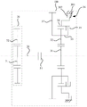
Fig. 1 is a schematic structural diagram of a transmission provided in an embodiment of the present disclosure. As shown in fig. 1, the transmission includes: a housing 100, a first variator, and an input spindle 20.
As shown in fig. 1, the first speed changing mechanism is located in the housing 100, the input spindle 20 is movably inserted into the housing 100, and the input spindle 20 is configured to be in transmission connection with at least one power source.
As shown in fig. 1, the first speed change mechanism includes: the planetary gear set comprises a first central wheel 31, a plurality of first planet wheels 32, a first planet carrier 33, a first gear ring 34, a first clutch 35 and a second clutch 36, wherein the first gear ring 34 is coaxially arranged with the first central wheel 31, the plurality of first planet wheels 32 are positioned between the first central wheel 31 and the first gear ring 34 and are all meshed with the first central wheel 31 and the first gear ring 34, the first central wheel 31 is coaxially connected with the input main shaft 20, and the first planet carrier 33 is in transmission connection with wheels 13.
The first clutch 35 is connected to the first ring gear 34 and the first carrier 33, respectively, for controlling the connection or disconnection between the first ring gear 34 and the first carrier 33, and the second clutch 36 is connected to the first ring gear 34 and the housing 100, respectively, for controlling the connection or disconnection between the first ring gear 34 and the housing 100.
In the transmission of the embodiment of the present disclosure, the power of the power source may be transmitted to the first sun gear 31 of the first transmission mechanism through the input main shaft 20, wherein the first transmission mechanism is provided with a first clutch 35 and a second clutch 36, the first clutch 35 can connect or disconnect the first ring gear 34 and the first carrier 33, and the second clutch 36 can connect or disconnect the first ring gear 34 and the housing 100. When the first clutch 35 connects the first ring gear 34 and the first carrier 33, the first ring gear 34 and the first carrier 33 are combined into a whole, and at this time, the first center wheel 31 is driving, the first carrier 33 is driven, and the first center wheel 31 and the first carrier 33 rotate at a first speed ratio; when the second clutch 36 connects the first ring gear 34 and the housing 100, the first ring gear 34 is fixed, the first sun gear 31 is driven, the first carrier 33 is driven, and the first sun gear 31 and the first carrier 33 rotate at the second speed ratio. Therefore, by controlling the engagement of the first clutch 35 or the second clutch 36, the first carrier 33 can be controlled to output different rotation speeds to drive the wheels 13 to rotate, so that multi-gear shifting adjustment is realized. In addition, the gearbox is only provided with one input shaft, so that various parts in the gearbox are effectively reduced, and the manufacturing cost of the gearbox is reduced.
Alternatively, as shown in fig. 1, each of the first clutch 35 and the second clutch 36 includes: a flywheel 301 and a driven disk 302, the flywheel 301 and the driven disk 302 being configured to be operably connected or disconnected.
In the embodiment of the present disclosure, the flywheel 301 of the clutch can move in the driven disc 302 along the axial direction of the driven disc 302 to be attached to or detached from the driven disc 302, so as to realize the coupling or detachment of the flywheel 301 and the driven disc 302, and complete the clutch action of the clutch.
As shown in fig. 1, the flywheel 301 of the first clutch 35 is coaxially connected to the first carrier 33, and the driven plate 302 of the first clutch 35 is coaxially connected to the first ring gear 34. The first ring gear 34 and the first carrier 33 are connected by the first clutch 35, so that the first ring gear 34 and the first carrier 33 are integrated when the first clutch 35 is controlled to be combined, the first ring gear 34 and the first carrier 33 rotate together, and the first carrier 33 is free to rotate relative to the first ring gear 34 when the first clutch 35 is controlled to be separated.
As shown in fig. 1, the flywheel 301 of the second clutch 36 is coaxially connected to the first ring gear 34, and the driven plate 302 of the second clutch 36 is connected to the housing 100. The first ring gear 34 is connected to the housing 100 by the second clutch 36, and when the second clutch 36 is controlled to be engaged, the first ring gear 34 is fixed to the housing 100 to brake the first ring gear 34, and when the second clutch 36 is controlled to be disengaged, the first ring gear 34 is allowed to rotate freely with respect to the housing 100.
When the first clutch 35 is disengaged and the second clutch 36 is engaged, the first ring gear 34 is fixed, and the power of the power source is transmitted to the first carrier 33, driving the wheels 13 to rotate. In this mode, the rotation speed of the first carrier 33 is lower than the rotation speed of the first sun gear 31, which is a low speed mode, and is suitable for the working conditions of the automobile cruise at a constant speed and the like with low power requirements.
When the first clutch 35 is engaged and the second clutch 36 is disengaged, the first ring gear 34 and the first carrier 33 are fixed to each other, and the power of the power source is transmitted to the first carrier 33 to rotate the wheels 13. In this mode, the rotation speed of the first sun gear 31 is the same as the rotation speed of the first carrier 33, i.e., the medium-high speed mode, and is suitable for the working conditions with high power demand, such as high-speed running of the vehicle.
In other implementations, both the first clutch 35 and the second clutch 36 may be disengaged so that power from the first power source is not transferred to the first carrier 33, i.e., in neutral mode.
Optionally, as shown in fig. 1, the first speed changing mechanism further includes a gear ring 37, the gear ring 37 is coaxially connected with the first carrier 33, the gear ring 37 and the first clutch 35 are respectively located on both sides of the first planetary gear 32, and the gear ring 37 is in transmission connection with the wheel 13.
The ring gear 37 has a ring-shaped structure, and the outer wall surface of the ring gear 37 has a gear. The gear ring 37 may be coaxially sleeved outside the first carrier 33, or may be coaxially connected to the first carrier 33 through another connecting structure, so that the rotation of the first carrier 33 can drive the gear ring 37 to rotate together.
Thus, the first carrier 33 is provided with the ring gear 37, and the wheel 13 is meshed with the first carrier 33 through the gear, so that the first carrier 33 can transmit the power in the first speed change mechanism to the wheel 13, and the wheel 13 is driven to rotate. In addition, a main shaft is not arranged between the wheels 13 and the first speed change mechanism, so that various transmission parts in the gearbox are effectively reduced, and the manufacturing cost of the gearbox is reduced.
As shown in fig. 1, the gear ring 37 and the first clutch 35 are respectively located on two sides of the first planet gear 32, so that the first clutch 35 and the gear ring 37 are prevented from being arranged on the same side to influence the transmission connection between the gear and the wheel 13, and thus, parts are reasonably distributed, and the reliability of the gearbox is improved.
Alternatively, as shown in fig. 1, the input spindle 20 includes a first section 21 and a second section 22, the first section 21 and the second section 22 are coaxially spaced apart; the gearbox further comprises a second variator and a third clutch 51, both the second variator and the third clutch 51 being located within the housing 100.
The second speed change mechanism has an input part and an output part, the input part is in transmission connection with the second section 22, the output part is in transmission connection with the power generation mechanism, the first central wheel 31 is coaxially connected with the first section 21, and the third clutch 51 is respectively connected with the first section 21 and the second section 22.
In the above implementation, the second speed change mechanism is provided to connect the input main shaft 20 and the power generation mechanism, so as to satisfy the power generation function of the hybrid system. A third clutch 51 is provided between the first center wheel 31 and the second center road, and the third clutch 51 is used for interrupting the power transmission between the first transmission mechanism and the second transmission mechanism, so that the hybrid power can be selectively set in a power generation mode or a driving mode, and a situation that when the vehicle is driven to run, part of the power is transmitted to the second transmission mechanism and the power of the power source is completely used for driving the vehicle to run can be prevented.
In one implementation, as shown in fig. 1, the second speed change mechanism includes: a second central gear 41, a second planet carrier 42, a plurality of second planet gears 43, a second gear ring 44, a fourth clutch 45 and a fifth clutch 46, wherein the second gear ring 44 is coaxially arranged with the second central gear 41, the plurality of second planet gears 43 are positioned between the second central gear 41 and the second gear ring 44 and are respectively meshed with the second central gear 41 and the second gear ring 44, the second central gear 41 is coaxially connected with the input main shaft 20, and the second planet carrier 42 is used for being in transmission connection with the power generation mechanism.
The fourth clutch 45 is connected to the second ring gear 44 and the second planet carrier 42 respectively for controlling the connection or disconnection between the second ring gear 44 and the second planet carrier 42, and the fifth clutch 46 is connected to the second ring gear 44 and the casing 100 respectively for controlling the connection or disconnection between the second ring gear 44 and the casing 100.
In the above-described implementation, the power of the power source can be transmitted to the second sun gear 41 of the second transmission mechanism through the input main shaft 20, wherein the second transmission mechanism is provided with the fourth clutch 45 and the fifth clutch 46, the fourth clutch 45 can connect or disconnect the second ring gear 44 and the second carrier 42, and the fifth clutch 46 can connect or disconnect the second ring gear 44 and the housing 100. When the fourth clutch 45 connects the second ring gear 44 and the second carrier 42, the second ring gear 44 and the second carrier 42 are combined into a whole, and the second carrier 42 and the second center gear 41 rotate at the first speed ratio; when the fifth clutch 46 connects the second ring gear 44 and the housing 100, the second ring gear 44 is fixed, and the second carrier 42 and the second sun gear 41 rotate at the second speed ratio. By controlling the engagement of the fourth clutch 45 or the fifth clutch 46, the power source can be controlled to rotate at different rotating speeds at the same speed, so that the purpose of generating power with different powers can be achieved, the performance of the power generating mechanism can be fully exerted, and the power generating efficiency of the hybrid power system can be improved.
In the embodiment of the present disclosure, the manner in which the fourth clutch 45 connects the carrier and the ring gear, and the manner in which the fifth clutch 46 connects the ring gear and the housing 100 may be as described above.
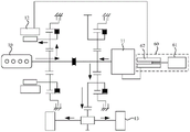
In another implementation, fig. 2 is a schematic structural diagram of another transmission provided in the embodiment of the present disclosure. As shown in fig. 2, the second transmission mechanism comprises a gear train 70, an input gear 71 of the gear train 70 is coaxially connected with the input spindle 20, and an output gear 72 of the gear train 70 is used for being in transmission connection with the power generation mechanism.
Through the arrangement of the gear train, the gear train is respectively in transmission connection with the power generation mechanism and the input spindle 20, so that the purpose of driving the power generation mechanism to generate power by the power source is achieved. Compared with a planetary gear train, the structure of the gear train is simpler, so that the gear train is convenient to process and manufacture, and the cost of the gearbox can be effectively reduced.
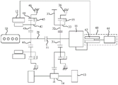
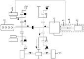
Fig. 3 is a schematic structural diagram of a hybrid power system provided in an embodiment of the present disclosure. As shown in fig. 3, the hybrid system includes a first power source, a second power source, a power generation mechanism, and the aforementioned transmission.
The first power source is an engine 10, the second power source is a first motor 11, and the power generation mechanism is a second motor 12.
As shown in fig. 3, the engine 10, the first motor 11 and the second motor 12 are all located outside the casing 100, an output shaft of the engine 10 and an output shaft of the first motor 11 are both in transmission connection with the input spindle 20, the engine 10 and the first motor 11 are located on both sides of the third clutch 51, and an output shaft of the second motor 12 is coaxially connected with the first carrier 33.
In the embodiment of the present disclosure, the engine 10 and the first motor 11 are provided as power sources, and the second motor 12 is provided as a power generation mechanism, so as to form a hybrid power system, the hybrid power system can transmit the power of the two power sources to the first speed change mechanism through the gearbox, so as to drive the wheels 13, and the power generation mechanism can be controlled to generate power when the first power source works, so that the first power source works efficiently, and the power performance and the cruising ability of the hybrid power system are improved.
As shown in fig. 3, the engine 10 and the first motor 11 are located at both sides of the third clutch 51, so that the third clutch 51 is controlled to block power transmission between the engine 10 and the first motor 11, and when the engine 10 alone drives the second motor 12 to generate power, the engine 10 is prevented from dragging the first motor 11 to rotate and losing power.
Optionally, as shown in fig. 3, the hybrid system further includes a power supply assembly 60, the power supply assembly 60 is located outside the casing 100, and the power supply assembly 60 includes: a battery 61 and two inverters 62, one of the two inverters 62 being connected between the battery 61 and the first motor 11, and the other of the two inverters 62 being connected between the battery 61 and the second motor 12.
By providing two inverters 62, one for connecting the battery 61 and the first motor 11 and the other for connecting the battery 61 and the second motor 12. The battery 61 is a rechargeable battery 61, and the inverter 62 is disposed on an output circuit of the battery 61 and is configured to convert direct current output by the battery 61 into three-phase alternating current to drive the first motor 11 or the second motor 12. In addition, the inverter 62 and the transformer are integrated in the embodiment of the present disclosure, which facilitates installation and saves installation space.
Optionally, as shown in fig. 3, the hybrid power system further comprises a differential 14, the differential 14 is in transmission connection with the first carrier 33, and the differential 14 is used for being in transmission connection with the wheels 13.
In the disclosed embodiment, the input gear of the differential 14 meshes with the ring gear 37 on the first carrier 33, and thus can receive power transmitted from the power source for the purpose of driving the wheels 13 to rotate.
Wherein the differential 14 enables wheels 13 connected to the output shaft of the differential 14 to rotate at different rotational speeds. When the automobile runs in a turning way, the turning radius of the inner wheel 13 of the automobile is different from that of the outer wheel 13 of the automobile, and the turning radius of the outer wheel 13 is larger than that of the inner wheel 13, so that the rotating speed of the outer wheel 13 is required to be higher than that of the inner wheel 13 during turning, and the two wheels 13 can roll at different rotating speeds by utilizing the differential 14, so that the difference of the rotating speeds of the two wheels 13 is realized.
Embodiments of the present disclosure provide an automobile comprising a hybrid powertrain as described above and an automobile body, the hybrid powertrain being located within the automobile body.
The hybrid power system provided by the embodiment of the present disclosure can operate in any one of power modes, including a pure electric mode, a hybrid driving mode, an engine 10 direct drive mode, and an energy recovery mode.
The following describes each power mode of the hybrid system with reference to the hybrid system shown in fig. 3 as an example:
in the embodiment of the present disclosure, the electric-only mode includes two modes.
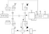
In a first mode, fig. 4 is a schematic energy transmission diagram of a hybrid system in an electric-only mode according to an embodiment of the present disclosure. As shown in fig. 4, when the hybrid system is switched to the electric only mode, the engine 10 and the second electric machine 12 are not operated, the third clutch 51 is disengaged, the first clutch 35 is disengaged, the second clutch 36 is engaged, and the first electric machine 11 is operated.
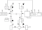
In a second mode, fig. 5 is a schematic energy transmission diagram of a hybrid system in an electric-only mode according to an embodiment of the disclosure. As shown in fig. 5, when the hybrid system is switched to the electric only mode, the engine 10 and the second electric machine 12 are not operated, the third clutch 51 is disengaged, the first clutch 35 is engaged, the second clutch 36 is disengaged, and the first electric machine 11 is operated.
In the above two implementation manners, the battery 61 of the power supply assembly 60 discharges, the inverter 62 converts the dc power into the three-phase ac power and then drives the output shaft of the first motor 11 to rotate, and the power of the first motor 11 is transmitted to the first planet carrier 33 through the first transmission mechanism to drive the wheels 13, so as to implement the pure electric mode.
Optionally, the vehicle can also be driven by the first electric machine 11 to run in reverse gear in the electric-only mode. In reverse, the engine 10 and the second electric machine 12 are not operated, the third clutch 51 is disengaged, one of the first clutch 35 and the second clutch 36 is engaged and the other is disengaged, and the first electric machine 11 is reversed to effect reverse.
In the disclosed embodiment, the hybrid mode includes four modes.
FIG. 6 is a schematic energy transfer diagram of a hybrid powertrain system in a hybrid mode provided by an embodiment of the present disclosure. In the first mode, as shown in fig. 6, the engine 10 is operated and drives the second electric machine 12 to generate electricity, the first electric machine 11 is operated, and the vehicle is driven by the first electric machine 11 alone. At this time, the first clutch 35 is disengaged, the second clutch 36 is engaged, the third clutch 51 is disengaged, the fourth clutch 45 is disengaged, and the fifth clutch 46 is engaged.
FIG. 7 is a schematic diagram of energy transfer of a hybrid powertrain system in a hybrid mode according to an embodiment of the disclosure. In the second mode, as shown in fig. 7, the engine 10 is operated and drives the second electric machine 12 to generate electric power, the first electric machine 11 is operated, and the vehicle is driven by the first electric machine 11 alone. At this time, the first clutch 35 is disengaged, the second clutch 36 is engaged, the third clutch 51 is disengaged, the fourth clutch 45 is engaged, and the fifth clutch 46 is disengaged.
In the two modes, the power of the engine 10 is transmitted to the second motor 12 sequentially through the input main shaft 20 and the first speed change mechanism to drive the second motor 12 to generate power; the power of the first motor 11 passes through the input spindle 20 and the first transmission mechanism in turn to drive the wheels 13 to rotate.
FIG. 8 is a schematic energy transfer diagram of a hybrid powertrain system in a hybrid mode provided by an embodiment of the present disclosure. As shown in fig. 8, in the third mode, the engine 10 is operated and drives the second motor 12 to generate power and drive the vehicle to run, the first motor 11 is operated, and the vehicle is driven by the engine 10 and the first motor 11 together. At this time, the first clutch 35 is disengaged, the second clutch 36 is engaged, the third clutch 51 is engaged, the fourth clutch 45 is engaged, and the fifth clutch 46 is disengaged.
FIG. 9 is a schematic energy transfer diagram of a hybrid powertrain system in a hybrid mode provided by an embodiment of the present disclosure. As shown in fig. 9, in the fourth mode, the engine 10 is operated and drives the second motor 12 to generate power and drive the vehicle to run, the first motor 11 is operated, and the vehicle is driven by the engine 10 and the first motor 11 together. At this time, the first clutch 35 is engaged, the second clutch 36 is disengaged, the third clutch 51 is engaged, the fourth clutch 45 is engaged, and the fifth clutch 46 is disengaged.
In the two modes, a part of the power of the engine 10 is transmitted to the second motor 12 through the input main shaft 20 and the second speed change mechanism in sequence to drive the second motor 12 to generate power; another part of the power of the engine 10 is transmitted to the wheels 13 through the input main shaft 20, the third clutch 51 and the first transmission mechanism in sequence, so as to drive the wheels 13 to rotate. The power of the first motor 11 passes through the input spindle 20 and the first transmission mechanism in order to drive the wheels 13 to rotate.
In the disclosed embodiment, the direct drive mode of the engine 10 includes two modes.
FIG. 10 is a schematic energy transfer diagram of a hybrid power system in a direct drive mode of engine 10 according to an embodiment of the present disclosure. As shown in fig. 10, in the first mode, the engine 10 is operated and drives the second electric machine 12 to generate electricity and drive the vehicle to run, the first electric machine 11 is not operated, and the vehicle is driven by the engine 10 alone. At this time, the first clutch 35 is disengaged, the second clutch 36 is engaged, the third clutch 51 is engaged, the fourth clutch 45 is engaged, and the fifth clutch 46 is disengaged.
FIG. 11 is a schematic energy transfer diagram of a hybrid power system in a direct drive mode of engine 10 according to an embodiment of the present disclosure. In the second mode, as shown in fig. 11, the engine 10 is operated and drives the second electric machine 12 to generate electric power and drive the vehicle to run, the first electric machine 11 is not operated, and the vehicle is driven by the engine 10 alone. At this time, the first clutch 35 is engaged, the second clutch 36 is disengaged, the third clutch 51 is engaged, the fourth clutch 45 is engaged, and the fifth clutch 46 is disengaged.
In the two modes, a part of the power of the engine 10 is transmitted to the second motor 12 through the input main shaft 20 and the second speed change mechanism in sequence to drive the second motor 12 to generate power; another part of the power of the engine 10 is transmitted to the wheels 13 through the input main shaft 20, the third clutch 51 and the first transmission mechanism in order to drive the wheels 13 to rotate.
In the disclosed embodiment, the direct drive mode of the engine 10 includes two modes. When the hybrid system is switched to the energy recovery mode, the engine 10 and the second electric machine 12 are not operated, the third clutch 51 is disengaged, one of the first clutch 35 and the second clutch 36 is engaged and the other is disengaged, and the first electric machine 11 is in the power generation mode.
Exemplarily, fig. 12 is a schematic energy transmission diagram of a hybrid power system in an energy recovery mode according to an embodiment of the present disclosure. As shown in fig. 12, when the hybrid system is switched to the energy recovery mode, the engine 10 and the second motor 12 are not operated, the third clutch 51 is disengaged, the fourth clutch 45 is engaged, and the first motor 11 is in the power generation mode.
In the above implementation manner, when the vehicle is in a sliding or braking condition, the wheels 13 provide a reverse torque, and part of kinetic energy of the vehicle is transmitted to the first motor 11 through the second main shaft and the third speed change mechanism to be converted into electric energy, which is stored in the power supply assembly 60 for standby, so as to realize the energy recovery function of the first motor 11.
The above description is meant to be illustrative of the principles of the present disclosure and not to be taken in a limiting sense, and any modifications, equivalents, improvements and the like that are within the spirit and scope of the present disclosure are intended to be included therein.
Claims (10)
1. A transmission, characterized in that it comprises: a housing (100), a first transmission mechanism and an input main shaft (20);
the first speed change mechanism is positioned in the shell (100), the input main shaft (20) is movably inserted in the shell (100), and the input main shaft (20) is used for being in transmission connection with at least one power source;
the first speed change mechanism includes: the planetary gear set comprises a first central wheel (31), a plurality of first planetary wheels (32), a first planet carrier (33), a first gear ring (34), a first clutch (35) and a second clutch (36), wherein the first gear ring (34) is coaxially arranged with the first central wheel (31), the plurality of first planetary wheels (32) are positioned between the first central wheel (31) and the first gear ring (34) and are respectively meshed with the first central wheel (31) and the first gear ring (34), the first central wheel (31) is coaxially connected with an input spindle (20), and the first planet carrier (33) is in transmission connection with wheels (13);
the first clutch (35) is connected with the first gear ring (34) and the first planet carrier (33) respectively and used for controlling the connection or the disconnection of the first gear ring (34) and the first planet carrier (33), and the second clutch (36) is connected with the first gear ring (34) and the shell (100) respectively and used for controlling the connection or the disconnection of the first gear ring (34) and the shell (100).
2. Gearbox according to claim 1, characterised in that the flywheel (301) of the first clutch (35) is coaxially connected to the first carrier (33) and the driven disc (302) of the first clutch (35) is coaxially connected to the first ring gear (34);
the flywheel (301) of the second clutch (36) is coaxially connected with the first gear ring (34), and the driven disc (302) of the second clutch (36) is connected with the shell (100).
3. The gearbox according to claim 1, characterised in that the first gear shifting mechanism further comprises a toothed ring (37), the toothed ring (37) is coaxially connected with the first planet carrier (33), the toothed ring (37) and the first clutch (35) are respectively located on both sides of the first planet gear (32), and the toothed ring (37) is in driving connection with the wheel (13).
4. A gearbox according to any one of claims 1 to 3, characterised in that the input spindle (20) comprises a first section (21) and a second section (22), the first section (21) and the second section (22) being coaxially spaced apart;
the gearbox further comprises a second speed change mechanism and a third clutch (51), both the second speed change mechanism and the third clutch (51) being located within the housing (100);
the second speed change mechanism is provided with an input part and an output part, the input part is in transmission connection with the second section (22), the output part is used for being in transmission connection with the power generation mechanism, the first center wheel (31) is coaxially connected with the first section (21), and the third clutch (51) is respectively connected with the first section (21) and the second section (22).
5. A gearbox according to claim 4, in which the second variator comprises: a second central wheel (41), a second planet carrier (42), a plurality of second planet wheels (43), a second gear ring (44), a fourth clutch (45) and a fifth clutch (46), wherein the second gear ring (44) is coaxially arranged with the second central wheel (41), the plurality of second planet wheels (43) are positioned between the second central wheel (41) and the second gear ring (44) and are respectively meshed with the second central wheel (41) and the second gear ring (44), the second central wheel (41) is coaxially connected with the input main shaft (20), and the second planet carrier (42) is used for being in transmission connection with a power generation mechanism;
the fourth clutch (45) is respectively connected with the second gear ring (44) and the second planet carrier (42) and used for controlling the connection or the separation of the second gear ring (44) and the second planet carrier (42), and the fifth clutch (46) is respectively connected with the second gear ring (44) and the shell (100) and used for controlling the connection or the separation of the second gear ring (44) and the shell (100).
6. The gearbox according to claim 4, characterised in that the second gear shift mechanism comprises a gear train (70), an input gear of the gear train (70) being coaxially connected with the input spindle (20), an output gear of the gear train (70) being for driving connection with a power generating mechanism.
7. A hybrid system, characterized in that the hybrid system comprises a first power source, a second power source, a power generation mechanism and a gearbox according to claim 4, the first power source being an engine (10), the second power source being a first electric machine (11), the power generation mechanism being a second electric machine (12);
the engine (10), the first motor (11) and the second motor (12) are located outside the shell (100), an output shaft of the engine (10) and an output shaft of the first motor (11) are in transmission connection with the input spindle (20), the engine (10) and the first motor (11) are located on two sides of the third clutch (51), and an output shaft of the second motor (12) is coaxially connected with the first planet carrier (33).
8. The hybrid system according to claim 7, further comprising a power supply assembly (60), the power supply assembly (60) being located outside the housing (100), the power supply assembly (60) comprising: a battery (61) and two inverters (62), one of the two inverters (62) being connected between the battery (61) and the first motor (11), the other of the two inverters (62) being connected between the battery (61) and the second motor (12).
9. Hybrid system according to claim 7, characterized in that it further comprises a differential (14), said differential (14) being in driving connection with said first carrier (33), said differential (14) being intended to be in driving connection with a wheel (13).
10. A vehicle comprising a hybrid powertrain according to any one of claims 7 to 9 and a vehicle body, the hybrid powertrain being located within the vehicle body.
Priority Applications (2)
| Application Number | Priority Date | Filing Date | Title |
|---|---|---|---|
| CN202211045887.7A CN115246313A (en) | 2022-08-30 | 2022-08-30 | Gearbox, hybrid power system and automobile |
| PCT/CN2022/137113 WO2024045403A1 (en) | 2022-08-30 | 2022-12-07 | Gearbox, hybrid power system, and automobile |
Applications Claiming Priority (1)
| Application Number | Priority Date | Filing Date | Title |
|---|---|---|---|
| CN202211045887.7A CN115246313A (en) | 2022-08-30 | 2022-08-30 | Gearbox, hybrid power system and automobile |
Publications (1)
| Publication Number | Publication Date |
|---|---|
| CN115246313A true CN115246313A (en) | 2022-10-28 |
Family
ID=83699704
Family Applications (1)
| Application Number | Title | Priority Date | Filing Date |
|---|---|---|---|
| CN202211045887.7A Pending CN115246313A (en) | 2022-08-30 | 2022-08-30 | Gearbox, hybrid power system and automobile |
Country Status (2)
| Country | Link |
|---|---|
| CN (1) | CN115246313A (en) |
| WO (1) | WO2024045403A1 (en) |
Cited By (1)
| Publication number | Priority date | Publication date | Assignee | Title |
|---|---|---|---|---|
| WO2024045403A1 (en) * | 2022-08-30 | 2024-03-07 | 奇瑞汽车股份有限公司 | Gearbox, hybrid power system, and automobile |
Family Cites Families (7)
| Publication number | Priority date | Publication date | Assignee | Title |
|---|---|---|---|---|
| US6478705B1 (en) * | 2001-07-19 | 2002-11-12 | General Motors Corporation | Hybrid electric powertrain including a two-mode electrically variable transmission |
| CN102259580B (en) * | 2010-05-31 | 2014-07-16 | 上海汽车集团股份有限公司 | Hybrid power transmission system |
| CN102774265B (en) * | 2012-08-18 | 2015-09-16 | 天津市松正电动汽车技术股份有限公司 | A kind of hybrid electric drive system |
| CN102826002B (en) * | 2012-09-07 | 2015-12-23 | 天津市松正电动汽车技术股份有限公司 | A kind of parallel type mixed power driving device |
| CN213861837U (en) * | 2020-11-25 | 2021-08-03 | 蜂巢传动科技河北有限公司 | Multi-mode hybrid power speed change module and hybrid electric vehicle |
| CN113022294A (en) * | 2021-03-05 | 2021-06-25 | 江苏大学 | Single-planet-row type hybrid electric vehicle power coupling mechanism and dynamic coordination control method thereof |
| CN115246313A (en) * | 2022-08-30 | 2022-10-28 | 奇瑞汽车股份有限公司 | Gearbox, hybrid power system and automobile |
-
2022
- 2022-08-30 CN CN202211045887.7A patent/CN115246313A/en active Pending
- 2022-12-07 WO PCT/CN2022/137113 patent/WO2024045403A1/en unknown
Cited By (1)
| Publication number | Priority date | Publication date | Assignee | Title |
|---|---|---|---|---|
| WO2024045403A1 (en) * | 2022-08-30 | 2024-03-07 | 奇瑞汽车股份有限公司 | Gearbox, hybrid power system, and automobile |
Also Published As
| Publication number | Publication date |
|---|---|
| WO2024045403A1 (en) | 2024-03-07 |
Similar Documents
| Publication | Publication Date | Title |
|---|---|---|
| US20170282702A1 (en) | Hybrid transmission having fixed gear shift stage | |
| JP4240091B2 (en) | Power output device and hybrid vehicle | |
| CN204547733U (en) | Two gear variable speed drive systems of the plug-in hybrid-power automobile of single drive motor | |
| CN104648115A (en) | Two-shift variable speed drive system of plug-in type hybrid vehicle with integrated single-driving motor | |
| CN107599823B (en) | Differential multimode hybrid vehicle drive system | |
| CN111409472B (en) | Multi-mode coupling driving system of double-motor electric automobile | |
| CN110962571B (en) | Hybrid power driving system and vehicle | |
| CN111319449A (en) | Hybrid power coupling system and vehicle | |
| CN112622522A (en) | Two-gear coaxial electric drive axle with compact layout | |
| CN111907321A (en) | Transmission, vehicle power system and vehicle | |
| KR20100088226A (en) | Power train of an hybrid electric vehicle and manipulating method thereof | |
| WO2023071093A1 (en) | Hybrid system and vehicle | |
| CN115246313A (en) | Gearbox, hybrid power system and automobile | |
| CN115284864A (en) | Gearbox, hybrid power system and automobile | |
| CN219007575U (en) | Power transmission device and hybrid electric vehicle | |
| CN205044511U (en) | Hybrid power system of unpowered interrupt | |
| CN113335059B (en) | Transmission structure, power system of pure electric vehicle and control method | |
| CN116039364A (en) | Hybrid power system, control method of hybrid power system and vehicle | |
| CN110626161B (en) | Hybrid power driving system based on planetary gear mechanism | |
| CN211280622U (en) | Hybrid transmission system and vehicle | |
| CN107471996B (en) | Hybrid power driving system and hybrid electric vehicle | |
| CN102795093A (en) | Hybrid power transmission device and hybrid power automobile | |
| CN113858934A (en) | Hybrid power system and vehicle adopting same | |
| CN215552501U (en) | Power system and automobile | |
| CN218577505U (en) | Hybrid power system and automobile |
Legal Events
| Date | Code | Title | Description |
|---|---|---|---|
| PB01 | Publication | ||
| PB01 | Publication | ||
| SE01 | Entry into force of request for substantive examination | ||
| SE01 | Entry into force of request for substantive examination |