EP4393682A1 - Wire feeding mechanism suitable for fused deposition additive manufacturing of flexible wire - Google Patents
Wire feeding mechanism suitable for fused deposition additive manufacturing of flexible wire Download PDFInfo
- Publication number
- EP4393682A1 EP4393682A1 EP23866635.8A EP23866635A EP4393682A1 EP 4393682 A1 EP4393682 A1 EP 4393682A1 EP 23866635 A EP23866635 A EP 23866635A EP 4393682 A1 EP4393682 A1 EP 4393682A1
- Authority
- EP
- European Patent Office
- Prior art keywords
- wall
- wire
- bracket
- roller
- support housing
- Prior art date
- Legal status (The legal status is an assumption and is not a legal conclusion. Google has not performed a legal analysis and makes no representation as to the accuracy of the status listed.)
- Granted
Links
Images


Classifications
-
- B—PERFORMING OPERATIONS; TRANSPORTING
- B29—WORKING OF PLASTICS; WORKING OF SUBSTANCES IN A PLASTIC STATE IN GENERAL
- B29C—SHAPING OR JOINING OF PLASTICS; SHAPING OF MATERIAL IN A PLASTIC STATE, NOT OTHERWISE PROVIDED FOR; AFTER-TREATMENT OF THE SHAPED PRODUCTS, e.g. REPAIRING
- B29C64/00—Additive manufacturing, i.e. manufacturing of three-dimensional [3D] objects by additive deposition, additive agglomeration or additive layering, e.g. by 3D printing, stereolithography or selective laser sintering
- B29C64/10—Processes of additive manufacturing
- B29C64/106—Processes of additive manufacturing using only liquids or viscous materials, e.g. depositing a continuous bead of viscous material
- B29C64/118—Processes of additive manufacturing using only liquids or viscous materials, e.g. depositing a continuous bead of viscous material using filamentary material being melted, e.g. fused deposition modelling [FDM]
-
- B—PERFORMING OPERATIONS; TRANSPORTING
- B29—WORKING OF PLASTICS; WORKING OF SUBSTANCES IN A PLASTIC STATE IN GENERAL
- B29C—SHAPING OR JOINING OF PLASTICS; SHAPING OF MATERIAL IN A PLASTIC STATE, NOT OTHERWISE PROVIDED FOR; AFTER-TREATMENT OF THE SHAPED PRODUCTS, e.g. REPAIRING
- B29C64/00—Additive manufacturing, i.e. manufacturing of three-dimensional [3D] objects by additive deposition, additive agglomeration or additive layering, e.g. by 3D printing, stereolithography or selective laser sintering
- B29C64/20—Apparatus for additive manufacturing; Details thereof or accessories therefor
- B29C64/205—Means for applying layers
- B29C64/209—Heads; Nozzles
-
- B—PERFORMING OPERATIONS; TRANSPORTING
- B29—WORKING OF PLASTICS; WORKING OF SUBSTANCES IN A PLASTIC STATE IN GENERAL
- B29C—SHAPING OR JOINING OF PLASTICS; SHAPING OF MATERIAL IN A PLASTIC STATE, NOT OTHERWISE PROVIDED FOR; AFTER-TREATMENT OF THE SHAPED PRODUCTS, e.g. REPAIRING
- B29C64/00—Additive manufacturing, i.e. manufacturing of three-dimensional [3D] objects by additive deposition, additive agglomeration or additive layering, e.g. by 3D printing, stereolithography or selective laser sintering
- B29C64/30—Auxiliary operations or equipment
- B29C64/307—Handling of material to be used in additive manufacturing
- B29C64/321—Feeding
-
- B—PERFORMING OPERATIONS; TRANSPORTING
- B33—ADDITIVE MANUFACTURING TECHNOLOGY
- B33Y—ADDITIVE MANUFACTURING, i.e. MANUFACTURING OF THREE-DIMENSIONAL [3D] OBJECTS BY ADDITIVE DEPOSITION, ADDITIVE AGGLOMERATION OR ADDITIVE LAYERING, e.g. BY 3D PRINTING, STEREOLITHOGRAPHY OR SELECTIVE LASER SINTERING
- B33Y30/00—Apparatus for additive manufacturing; Details thereof or accessories therefor
-
- B—PERFORMING OPERATIONS; TRANSPORTING
- B33—ADDITIVE MANUFACTURING TECHNOLOGY
- B33Y—ADDITIVE MANUFACTURING, i.e. MANUFACTURING OF THREE-DIMENSIONAL [3D] OBJECTS BY ADDITIVE DEPOSITION, ADDITIVE AGGLOMERATION OR ADDITIVE LAYERING, e.g. BY 3D PRINTING, STEREOLITHOGRAPHY OR SELECTIVE LASER SINTERING
- B33Y40/00—Auxiliary operations or equipment, e.g. for material handling
-
- Y—GENERAL TAGGING OF NEW TECHNOLOGICAL DEVELOPMENTS; GENERAL TAGGING OF CROSS-SECTIONAL TECHNOLOGIES SPANNING OVER SEVERAL SECTIONS OF THE IPC; TECHNICAL SUBJECTS COVERED BY FORMER USPC CROSS-REFERENCE ART COLLECTIONS [XRACs] AND DIGESTS
- Y02—TECHNOLOGIES OR APPLICATIONS FOR MITIGATION OR ADAPTATION AGAINST CLIMATE CHANGE
- Y02P—CLIMATE CHANGE MITIGATION TECHNOLOGIES IN THE PRODUCTION OR PROCESSING OF GOODS
- Y02P10/00—Technologies related to metal processing
- Y02P10/25—Process efficiency
Definitions
- AM commonly known as 3D printing
- the technology has the characteristics of rapidity, high efficiency, flexibility, etc., and does not need traditional molds, tools and fixtures, but uses 3D design data to efficiently and accurately manufacture, on an AM device, parts with any complex shape and structure.
- the AM technology can process a wide range of raw materials.
- the AM technology of non-metallic materials mainly organic polymer materials
- a hook may be provided on the device for wire separation.
- a relatively soft flexible material such as a Thermoplastic Polyurethane (TPU) material
- TPU Thermoplastic Polyurethane
- the present invention discloses a wire feeding mechanism suitable for fused deposition AM of a flexible wire, which aims to solve the technical problem that when a flexible material is printed, the position in contact with a hook is likely to cause temporary accumulation and then cake.
- a wire feeding mechanism suitable for fused deposition Additive Manufacturing (AM) of a flexible wire comprising a support housing, a melting nozzle is arranged at the lower end of the support housing, a hook is connected to the inner wall of the top end of the support housing, a connecting rod is connected to the inner wall of one side of the support housing, a wire drawing mechanism is connected to one end of the connecting rod, the wire drawing mechanism is located below the hook, a limiting mechanism and a wire guide mechanism are connected to the inner wall of one side of the support housing, the limiting mechanism is located below the wire drawing mechanism, the wire guide mechanism is located below the limiting mechanism, the wire drawing mechanism comprises a support seat, the support seat is connected to the connecting rod, an electric chute is arranged in the inner wall of the top end of the support seat, an electric sliding block is movably connected to the inner wall of the electric chute in a clamped manner, a sixth bracket is connected to the outer wall of the top end of the electric sliding block, a plurality of third connecting shafts are arranged on the
- a wire drawing mechanism is arranged. Since the wire is a flexible wire, when the wire is hung on the hook and conveyed to the position of a melting nozzle under the action of a wire guide mechanism, the position in contact with the hook is likely to cause temporary accumulation and then cake.
- a sixth bracket is driven via an electric sliding block in the wire drawing mechanism to move along an electric chute in a support seat. When the electric sliding block moves to a high position of the electric chute, a fourth roller just contacts the bottom end of the wire on the hook, and the movement of the wire may also drive the fourth roller to move, thereby acting on a joint between the wire and the hook and reducing the risk of wire caking.
- the circulating movement of the electric sliding block in the electric chute also plays a role of assisting the wire to loosen the caking position.
- the electric sliding block slides to the lower end of the electric chute, the electric sliding block may be disconnected from the wire, thus avoiding a situation of knotting caused by torsion of the wire driven by the circulating movement.
- the wire guide mechanism comprises a limiting block, a third connecting rod is arranged at both sides of the limiting block, the third connecting rod is connected to the inner wall of the support housing, a third roller is arranged aside the limiting block, a plurality of rubber pads are arranged on the outer wall of the third roller at equal density, and the wire is located between the rubber pads and the limiting block;
- a gear is connected to the outer wall of one side of the third roller, a second gear is connected to the outer wall of the gear in a clamped manner, a second clamp block is connected to the outer wall of one side of the second gear, and a motor is connected to one end of the second clamp block;
- a fifth bracket is movably connected to the inner wall of the second clamp block in a clamped manner, a connecting seat is arranged on the inner walls of two sides of the fifth bracket, the connecting seat is connected to the gear and the third roller, respectively, a third bracket is arranged on the outer wall of one side of the fifth bracket, the third bracket is connected to
- the second pneumatic rod is arranged, and a telescopic length of the second pneumatic rod is controlled, so that the position between the limiting block and the rubber pad on the third roller can be further controlled.
- the wire guide mechanism is applicable to wires of different models for use. Meanwhile, through the arranged rubber pad, the wire with the material being a flexible wire can be protected from damage during wire guide while the third roller is ensured to tightly contact the wire, thus avoiding the wire from being deformed by extrusion of the third roller.
- the limiting mechanism comprises a bracket and a second bracket, a second connecting rod is connected to the outer wall of one side of the bracket, the second connecting rod is connected to the support housing, a connecting shaft is arranged on the inner wall of the bracket, and a roller is connected to the outer wall of the connecting shaft in a sleeving manner; ball bearings are arranged on the inner walls of two sides of the second bracket, a clamp block is connected to the inner walls of the ball bearings in a clamped manner, a second connecting shaft is connected to one side of the clamp block, a second roller is connected to the outer wall of the second connecting shaft in a sleeving manner, soft bumps are arranged on the outer wall of the second roller at equal density, a pneumatic rod is connected to one side of the second bracket, and the other side of the pneumatic rod is connected to the support housing.
- the working principle of the present invention is: when in use, the sixth bracket is driven via the electric sliding block in the wire drawing mechanism to move along the electric chute in the support seat.
- the fourth roller just contacts the bottom end of the wire on the hook, and the movement of the wire may also drive the fourth roller to move, thereby acting on a joint between the wire and the hook and reducing the risk of wire caking.
- the circulating movement of the electric sliding block in the electric chute also plays a role of assisting the wire to loosen the caking position.
- the electric sliding block slides to the lower end of the electric chute, the electric sliding block may be disconnected from the wire, thus avoiding a situation of knotting caused by torsion of the wire driven by the circulating movement.
- a fifth bracket 34 is movably connected to the inner wall of the second clamp block 26 in a clamped manner, a connecting seat 37 is arranged on the inner walls of two sides of the fifth bracket 34, the connecting seat 37 is connected to the gear 24 and the third roller 23, respectively, a third bracket 28 is arranged on the outer wall of one side of the fifth bracket 34, the third bracket 28 is connected to the motor 25, a fourth bracket 30 is movably connected to the outer wall of the fifth bracket 34, a second pneumatic rod 31 is arranged on the inner wall of one side of the fourth bracket 30, and the second pneumatic rod 31 is connected to the fifth bracket 34 at the same time.
- the sliding block 35 is connected into the top chute 33 in a clamped manner, and the clamp strips 29 on the two sides are connected into the clamp slots 32 in a clamped manner, so that three orientations of the third roller 23 can all be limited, it can be guaranteed that the third roller 23 is not loosened and displaced during long-time use, the third roller 23 can be avoided from being separated from a clamping position with the limiting block 21, and the service life of the wire feeding mechanism can be guaranteed.
- ball bearings 15 are arranged on the inner walls of two sides of the second bracket 16, a clamp block 13 is connected to the inner walls of the ball bearings 15 in a clamped manner, a second connecting shaft 14 is connected to one side of the clamp block 13, a second roller 18 is connected to the outer wall of the second connecting shaft 14 in a sleeving manner, soft bumps 19 are arranged on the outer wall of the second roller 18 at equal density, a pneumatic rod 17 is connected to one side of the second bracket 16, and the other side of the pneumatic rod 17 is connected to the support housing 1.
- the sixth bracket 38 when in use, the sixth bracket 38 is driven via the electric sliding block 41 in the wire drawing mechanism 5 to move along the electric chute 42 in the support seat 43.
- the fourth roller 39 just contacts the bottom end of the wire 2 on the hook 4, and the movement of the wire 2 may also drive the fourth roller 39 to move, thereby acting on a joint between the wire 2 and the hook 4 and reducing the risk of wire 2 caking.
- the circulating movement of the electric sliding block 41 in the electric chute 42 also plays a role of assisting the wire 2 to loosen the caking position.
- the electric sliding block 41 slides to the lower end of the electric chute 42, the electric sliding block 41 may be disconnected from the wire 2, thus avoiding a situation of knotting caused by torsion of the wire 2 driven by the circulating movement.
Landscapes
- Chemical & Material Sciences (AREA)
- Engineering & Computer Science (AREA)
- Materials Engineering (AREA)
- Manufacturing & Machinery (AREA)
- Physics & Mathematics (AREA)
- Mechanical Engineering (AREA)
- Optics & Photonics (AREA)
- Tyre Moulding (AREA)
- Wire Processing (AREA)
Abstract
Description
- The present invention relates to the technical field of Three-Dimensional (3D) printing, and in particular to a wire feeding mechanism suitable for fused deposition Additive Manufacturing (AM) of a flexible wire.
- At present, AM (commonly known as 3D printing) technology has become a research hotspot at home and abroad. The technology has the characteristics of rapidity, high efficiency, flexibility, etc., and does not need traditional molds, tools and fixtures, but uses 3D design data to efficiently and accurately manufacture, on an AM device, parts with any complex shape and structure. The AM technology can process a wide range of raw materials. The AM technology of non-metallic materials (mainly organic polymer materials) has been relatively mature.
- In the prior art, in order to prevent wire winding, a hook may be provided on the device for wire separation. But when a relatively soft flexible material such as a Thermoplastic Polyurethane (TPU) material is printed, the position in contact with the hook is likely to cause temporary accumulation and then cake, which affects the progress of wire feeding, and even directly affects the printing effect.
- In order to solve the above problem, the present invention discloses a wire feeding mechanism suitable for fused deposition AM of a flexible wire, which aims to solve the technical problem that when a flexible material is printed, the position in contact with a hook is likely to cause temporary accumulation and then cake.
- In order to achieve the above objectives, the present invention adopts the following technical solution:
- A wire feeding mechanism suitable for fused deposition Additive Manufacturing (AM) of a flexible wire, comprising a support housing, a melting nozzle is arranged at the lower end of the support housing, a hook is connected to the inner wall of the top end of the support housing, a connecting rod is connected to the inner wall of one side of the support housing, a wire drawing mechanism is connected to one end of the connecting rod, the wire drawing mechanism is located below the hook, a limiting mechanism and a wire guide mechanism are connected to the inner wall of one side of the support housing, the limiting mechanism is located below the wire drawing mechanism, the wire guide mechanism is located below the limiting mechanism, the wire drawing mechanism comprises a support seat, the support seat is connected to the connecting rod, an electric chute is arranged in the inner wall of the top end of the support seat, an electric sliding block is movably connected to the inner wall of the electric chute in a clamped manner, a sixth bracket is connected to the outer wall of the top end of the electric sliding block, a plurality of third connecting shafts are arranged on the inner wall of the sixth bracket, a fourth roller is connected to the outer wall of each of the third connecting shafts in a sleeving manner, a wire is arranged on the hook, and the wire passes through the limiting mechanism and the wire guide mechanism in sequence.
- A wire drawing mechanism is arranged. Since the wire is a flexible wire, when the wire is hung on the hook and conveyed to the position of a melting nozzle under the action of a wire guide mechanism, the position in contact with the hook is likely to cause temporary accumulation and then cake. A sixth bracket is driven via an electric sliding block in the wire drawing mechanism to move along an electric chute in a support seat. When the electric sliding block moves to a high position of the electric chute, a fourth roller just contacts the bottom end of the wire on the hook, and the movement of the wire may also drive the fourth roller to move, thereby acting on a joint between the wire and the hook and reducing the risk of wire caking. Meanwhile, the circulating movement of the electric sliding block in the electric chute also plays a role of assisting the wire to loosen the caking position. When the electric sliding block slides to the lower end of the electric chute, the electric sliding block may be disconnected from the wire, thus avoiding a situation of knotting caused by torsion of the wire driven by the circulating movement.
- In a preferred solution, the wire guide mechanism comprises a limiting block, a third connecting rod is arranged at both sides of the limiting block, the third connecting rod is connected to the inner wall of the support housing, a third roller is arranged aside the limiting block, a plurality of rubber pads are arranged on the outer wall of the third roller at equal density, and the wire is located between the rubber pads and the limiting block; a gear is connected to the outer wall of one side of the third roller, a second gear is connected to the outer wall of the gear in a clamped manner, a second clamp block is connected to the outer wall of one side of the second gear, and a motor is connected to one end of the second clamp block; a fifth bracket is movably connected to the inner wall of the second clamp block in a clamped manner, a connecting seat is arranged on the inner walls of two sides of the fifth bracket, the connecting seat is connected to the gear and the third roller, respectively, a third bracket is arranged on the outer wall of one side of the fifth bracket, the third bracket is connected to the motor, a fourth bracket is movably connected to the outer wall of the fifth bracket, a second pneumatic rod is arranged on the inner wall of one side of the fourth bracket, and the second pneumatic rod is connected to the fifth bracket at the same time.
- The second pneumatic rod is arranged, and a telescopic length of the second pneumatic rod is controlled, so that the position between the limiting block and the rubber pad on the third roller can be further controlled. Accordingly, the wire guide mechanism is applicable to wires of different models for use. Meanwhile, through the arranged rubber pad, the wire with the material being a flexible wire can be protected from damage during wire guide while the third roller is ensured to tightly contact the wire, thus avoiding the wire from being deformed by extrusion of the third roller.
- Further improvement, clamp strips are arranged on the outer walls of the two sides of the fifth bracket, clamp slots are formed in the inner walls of the two sides of the fourth bracket, and the fifth bracket is movably connected to the fourth bracket by interconnecting the clamp strips and the clamp slots in a clamped manner; a support plate is connected to the outer wall of one side of the fifth bracket, a sliding block is arranged at the top end of the support plate, a top chute is connected to the top end of the fourth bracket, and the sliding block is movably connected into the top chute in a clamped manner.
- The second clamp block is connected to the inner wall of the fifth bracket in a clamped manner, so that the position of the second gear is ensured, and the second gear can be ensured to be perfectly clamped with the gear. Meanwhile, the sliding block is connected into the top chute in a clamped manner, and the clamp strips on the two sides are connected into the clamp slots in a clamped manner, so that three orientations of the third roller can all be limited, it can be guaranteed that the third roller is not loosened and displaced during long-time use, the third roller can be avoided from being separated from a clamping position with the limiting block, and the service life of the wire feeding mechanism can be guaranteed.
- Further improvement, the limiting mechanism comprises a bracket and a second bracket, a second connecting rod is connected to the outer wall of one side of the bracket, the second connecting rod is connected to the support housing, a connecting shaft is arranged on the inner wall of the bracket, and a roller is connected to the outer wall of the connecting shaft in a sleeving manner; ball bearings are arranged on the inner walls of two sides of the second bracket, a clamp block is connected to the inner walls of the ball bearings in a clamped manner, a second connecting shaft is connected to one side of the clamp block, a second roller is connected to the outer wall of the second connecting shaft in a sleeving manner, soft bumps are arranged on the outer wall of the second roller at equal density, a pneumatic rod is connected to one side of the second bracket, and the other side of the pneumatic rod is connected to the support housing.
- The limiting mechanism is arranged and acts on the two sides of the wire, so that the wire can accurately enter the wire guide mechanism, and the wire can be avoided from dislocation to cause the wire guide mechanism incapable of normally guiding the wire. Meanwhile, the soft bumps are arranged on the outer wall of the second roller at equal density, so that when the wire is limited and contacts the soft bumps, the second roller may be driven to rotate. Under the action of the ball bearings, the friction subjected to by the second roller during rotation can be reduced. In a rotating process of the second roller, the soft bumps can be intermittently separated from the wire, so that the surface of wire can be avoided from abrasion caused due to long-term contact with the wire.
- The working principle of the present invention is: when in use, the sixth bracket is driven via the electric sliding block in the wire drawing mechanism to move along the electric chute in the support seat. When the electric sliding block moves to a high position of the electric chute, the fourth roller just contacts the bottom end of the wire on the hook, and the movement of the wire may also drive the fourth roller to move, thereby acting on a joint between the wire and the hook and reducing the risk of wire caking. Meanwhile, the circulating movement of the electric sliding block in the electric chute also plays a role of assisting the wire to loosen the caking position. When the electric sliding block slides to the lower end of the electric chute, the electric sliding block may be disconnected from the wire, thus avoiding a situation of knotting caused by torsion of the wire driven by the circulating movement.
- It can be seen from the above that the beneficial effects of the present invention are that:
- 1. The wire feeding mechanism suitable for fused deposition AM of a flexible wire has the effect of reducing the risk of caking at the joint between the wire and the hook.
- 2. The printing effect is ensured and the work efficiency is improved.
- 3. The service life of the device is prolonged.
-
-
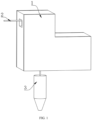
FIG. 1 is a schematic structural diagram of overall appearance of a wire feeding mechanism suitable for fused deposition AM of a flexible wire proposed by the present invention. -
FIG. 2 is an overall schematic structural diagram of inside of a wire feeding mechanism suitable for fused deposition AM of a flexible wire proposed by the present invention. -
FIG. 3 is a schematic structural diagram of splitting a limiting mechanism of a wire feeding mechanism suitable for fused deposition AM of a flexible wire proposed by the present invention. -
FIG. 4 is a schematic structural diagram of splitting a wire guide mechanism of a wire feeding mechanism suitable for fused deposition AM of a flexible wire proposed by the present invention. -
FIG. 5 is a schematic structural diagram of splitting a wire drawing mechanism of a wire feeding mechanism suitable for fused deposition AM of a flexible wire proposed by the present invention. - In the
figure: 1 , support housing; 2, wire; 3, melting nozzle; 4, hook; 5, wire drawing mechanism; 6, connecting rod; 7, limiting mechanism; 8, wire guide mechanism; 9, second connecting rod; 10, bracket; 11, connecting shaft; 12, roller; 13, clamp block; 14, second connecting shaft; 15, ball bearing; 16, second bracket; 17, pneumatic rod; 18, second roller; 19, soft bump; 20, third connecting rod; 21, limiting block; 22, rubber pad; 23, third roller; 24, gear; 25, motor; 26, second clamp block; 27, second gear; 28, third bracket; 29, clamp strip; 30, fourth bracket; 31, second pneumatic rod; 32, clamp slot; 33, top chute; 34, fifth bracket; 35, sliding block; 36, support plate; 37, connecting seat; 38, sixth bracket; 39, fourth roller; 40, third connecting shaft; 41, electric sliding block; 42, electric chute; and 43, support seat. - The present invention is further illustrated below in conjunction with the drawings and specific embodiments, and it should be understood that the following specific embodiments are merely used to illustrate the present invention and not to limit the scope of the present invention. It should be noted that the words "front", "back", "left", "right", "upper", and "lower" used in the following description refer to directions in the drawings, and the words "inner" and "outer" respectively refer to directions toward or away from the geometric center of a particular component.
- A wire feeding mechanism suitable for fused deposition AM of a flexible wire disclosed in the present invention is mainly applied to a scenario of 3D printing.
- Referring to
FIGS. 1 ,2 and5 , a wire feeding mechanism suitable for fused deposition AM of a flexible wire includes asupport housing 1. Amelting nozzle 3 is arranged at the lower end of thesupport housing 1, ahook 4 is connected to the inner wall of the top end of thesupport housing 1, a connectingrod 6 is connected to the inner wall of one side of thesupport housing 1, awire drawing mechanism 5 is connected to one end of the connectingrod 6, thewire drawing mechanism 5 is located below thehook 4, alimiting mechanism 7 and awire guide mechanism 8 are connected to the inner wall of one side of thesupport housing 1, thelimiting mechanism 7 is located below thewire drawing mechanism 5, thewire guide mechanism 8 is located below thelimiting mechanism 7, the wire drawing mechanism 50 includes asupport seat 43, thesupport seat 43 is connected to theconnecting rod 6, anelectric chute 42 is arranged in the inner wall of the top end of thesupport seat 43, an electric slidingblock 41 is movably connected to the inner wall of theelectric chute 42 in a clamped manner, asixth bracket 38 is connected to the outer wall of the top end of the electric slidingblock 41, a plurality of third connectingshafts 40 are arranged on the inner wall of thesixth bracket 38, afourth roller 39 is connected to the outer walls of the plurality of third connectingshafts 40 in a sleeving manner, awire 2 is arranged on thehook 4, and thewire 2 passes through thelimiting mechanism 7 and thewire guide mechanism 8 at the same time. - Referring to
FIG. 4 , in a preferred implementation, thewire guide mechanism 8 includes alimiting block 21, a third connectingrod 20 is arranged at both sides of the limitingblock 21, the third connectingrod 20 is connected to the inner wall of thesupport housing 1, thewire guide mechanism 8 includes athird roller 23, a plurality ofrubber pads 22 are arranged on the outer wall of thethird roller 23 at equal density, and thewire 2 is located between therubber pads 22 and thelimiting block 21. - Referring to
FIG. 4 , in a preferred implementation, agear 24 is connected to the outer wall of one side of thethird roller 23, asecond gear 27 is connected to the outer wall of thegear 24 in a clamped manner, asecond clamp block 26 is connected to the outer wall of one side of thesecond gear 27, and amotor 25 is connected to one end of thesecond clamp block 26. - Referring to
FIG. 4 , in a preferred implementation, afifth bracket 34 is movably connected to the inner wall of thesecond clamp block 26 in a clamped manner, a connectingseat 37 is arranged on the inner walls of two sides of thefifth bracket 34, the connectingseat 37 is connected to thegear 24 and thethird roller 23, respectively, athird bracket 28 is arranged on the outer wall of one side of thefifth bracket 34, thethird bracket 28 is connected to themotor 25, afourth bracket 30 is movably connected to the outer wall of thefifth bracket 34, a secondpneumatic rod 31 is arranged on the inner wall of one side of thefourth bracket 30, and the secondpneumatic rod 31 is connected to thefifth bracket 34 at the same time. The secondpneumatic rod 31 is arranged, and a telescopic length of the secondpneumatic rod 31 is controlled, so that the position between thelimiting block 21 and therubber pad 22 on thethird roller 23 can be further controlled. Accordingly, thewire guide mechanism 8 is applicable towires 2 of different models for use. Meanwhile, through the arrangedrubber pad 22, thewire 2 with the material being a flexible wire can be protected from damage during wire guide while thethird roller 23 is ensured to tightly contact thewire 2, thus avoiding thewire 2 from being deformed by extrusion of thethird roller 23. - Referring to
FIG. 4 , in a preferred implementation,clamp strips 29 are arranged on the outer walls of the two sides of thefifth bracket 34,clamp slots 32 are formed in the inner walls of the two sides of thefourth bracket 30, and thefifth bracket 34 is movably connected to thefourth bracket 30 by interconnecting theclamp strips 29 and theclamp slots 32 in a clamped manner. - Referring to
FIG. 4 , in a preferred implementation, asupport plate 36 is connected to the outer wall of one side of thefifth bracket 34, a slidingblock 35 is arranged at the top end of thesupport plate 36, atop chute 33 is connected to the top end of thefourth bracket 30, and thesliding block 35 is movably connected into thetop chute 33 in a clamped manner. Thesecond clamp block 26 is connected to the inner wall of thefifth bracket 34 in a clamped manner, so that the position of thesecond gear 27 is ensured, and thesecond gear 27 can be ensured to be perfectly clamped with thegear 24. Meanwhile, the slidingblock 35 is connected into thetop chute 33 in a clamped manner, and theclamp strips 29 on the two sides are connected into theclamp slots 32 in a clamped manner, so that three orientations of thethird roller 23 can all be limited, it can be guaranteed that thethird roller 23 is not loosened and displaced during long-time use, thethird roller 23 can be avoided from being separated from a clamping position with thelimiting block 21, and the service life of the wire feeding mechanism can be guaranteed. - Referring to
FIG. 3 , in a preferred implementation, the limitingmechanism 7 includes abracket 10 and asecond bracket 16, a second connectingrod 9 is connected to the outer wall of one side of thebracket 10, the second connectingrod 9 is connected to thesupport housing 1, a connectingshaft 11 is arranged on the inner wall of thebracket 10, and aroller 12 is connected to the outer wall of the connectingshaft 11 in a sleeving manner. - Referring to
FIG. 3 , in a preferred implementation,ball bearings 15 are arranged on the inner walls of two sides of thesecond bracket 16, aclamp block 13 is connected to the inner walls of theball bearings 15 in a clamped manner, a second connectingshaft 14 is connected to one side of theclamp block 13, asecond roller 18 is connected to the outer wall of the second connectingshaft 14 in a sleeving manner,soft bumps 19 are arranged on the outer wall of thesecond roller 18 at equal density, apneumatic rod 17 is connected to one side of thesecond bracket 16, and the other side of thepneumatic rod 17 is connected to thesupport housing 1. The limitingmechanism 7 is arranged and acts on the two sides of thewire 2, so that thewire 2 can accurately enter thewire guide mechanism 8, and thewire 2 can be avoided from dislocation to cause thewire guide mechanism 8 incapable of normally guiding the wire. Meanwhile, thesoft bumps 19 are arranged on the outer wall of thesecond roller 18 at equal density, so that when thewire 2 is limited and contacts thesoft bumps 19, thesecond roller 18 may be driven to rotate. Under the action of theball bearings 15, the friction subjected to by thesecond roller 18 during rotation can be reduced. In a rotating process of thesecond roller 18, thesoft bumps 19 can be intermittently separated from thewire 2, so that the surface ofwire 2 can be avoided from abrasion caused due to long-term contact with thewire 2. - Working principle: when in use, the
sixth bracket 38 is driven via theelectric sliding block 41 in thewire drawing mechanism 5 to move along theelectric chute 42 in thesupport seat 43. When the electric slidingblock 41 moves to a high position of theelectric chute 42, thefourth roller 39 just contacts the bottom end of thewire 2 on thehook 4, and the movement of thewire 2 may also drive thefourth roller 39 to move, thereby acting on a joint between thewire 2 and thehook 4 and reducing the risk ofwire 2 caking. Meanwhile, the circulating movement of the electric slidingblock 41 in theelectric chute 42 also plays a role of assisting thewire 2 to loosen the caking position. When the electric slidingblock 41 slides to the lower end of theelectric chute 42, the electric slidingblock 41 may be disconnected from thewire 2, thus avoiding a situation of knotting caused by torsion of thewire 2 driven by the circulating movement. - The technical means disclosed by the solution of the present invention are not limited to these disclosed in the above implementations and further include the technical solution formed by any combination of the above technical features.
Claims (8)
- A wire feeding mechanism suitable for fused deposition Additive Manufacturing (AM) of a flexible wire, comprising a support housing (1), wherein a melting nozzle (3) is arranged at the lower end of the support housing (1), a hook (4) is connected to the inner wall of the top end of the support housing (1), a connecting rod (6) is connected to the inner wall of one side of the support housing (1), a wire drawing mechanism (5) is connected to one end of the connecting rod (6), the wire drawing mechanism (5) is located below the hook (4), a limiting mechanism (7) and a wire guide mechanism (8) are connected to the inner wall of one side of the support housing (1), the limiting mechanism (7) is located below the wire drawing mechanism (5), the wire guide mechanism (8) is located below the limiting mechanism (7), the wire drawing mechanism (50) comprises a support seat (43), the support seat (43) is connected to the connecting rod (6), an electric chute (42) is arranged in the inner wall of the top end of the support seat (43), an electric sliding block (41) is movably connected to the inner wall of the electric chute (42) in a clamped manner, a sixth bracket (38) is connected to the outer wall of the top end of the electric sliding block (41), a plurality of third connecting shafts (40) are arranged on the inner wall of the sixth bracket (38), a fourth roller (39) is connected to the outer wall of each of the third connecting shafts (40) in a sleeving manner, a wire (2) is arranged on the hook (4), and the wire (2) passes through the limiting mechanism (7) and the wire guide mechanism (8) in sequence.
- The wire feeding mechanism suitable for fused deposition AM of a flexible wire according to claim 1, wherein the wire guide mechanism (8) comprises a limiting block (21), a third connecting rod (20) is arranged at both sides of the limiting block (21), the third connecting rod (20) is connected to the inner wall of the support housing (1), a third roller (23) is arranged aside the limiting block (21), a plurality of rubber pads (22) are arranged on the outer wall of the third roller (23) at equal density, and the wire (2) is located between the rubber pads (22) and the limiting block (21).
- The wire feeding mechanism suitable for fused deposition AM of a flexible wire according to claim 2, wherein a gear (24) is connected to the outer wall of one side of the third roller (23), a second gear (27) is connected to the outer wall of the gear (24) in a clamped manner, a second clamp block (26) is connected to the outer wall of one side of the second gear (27), and a motor (25) is connected to one end of the second clamp block (26).
- The wire feeding mechanism suitable for fused deposition AM of a flexible wire according to claim 3, wherein a fifth bracket (34) is movably connected to the inner wall of the second clamp block (26) in a clamped manner, a connecting seat (37) is arranged on the inner walls of two sides of the fifth bracket (34), the connecting seat (37) is connected to the gear (24) and the third roller (23), respectively, a third bracket (28) is arranged on the outer wall of one side of the fifth bracket (34), the third bracket (28) is connected to the motor (25), a fourth bracket (30) is movably connected to the outer wall of the fifth bracket (34), a second pneumatic rod (31) is arranged on the inner wall of one side of the fourth bracket (30), and the second pneumatic rod (31) is connected to the fifth bracket (34) at the same time.
- The wire feeding mechanism suitable for fused deposition AM of a flexible wire according to claim 4, wherein clamp strips (29) are arranged on the outer walls of the two sides of the fifth bracket (34), clamp slots (32) are formed in the inner walls of the two sides of the fourth bracket (30), and the fifth bracket (34) is movably connected to the fourth bracket (30) by interconnecting the clamp strips (29) and the clamp slots (32) in a clamped manner.
- The wire feeding mechanism suitable for fused deposition AM of a flexible wire according to claim 5, wherein a support plate (36) is connected to the outer wall of one side of the fifth bracket (34), a sliding block (35) is arranged at the top end of the support plate (36), a top chute (33) is connected to the top end of the fourth bracket (30), and the sliding block (35) is movably connected into the top chute (33) in a clamped manner.
- The wire feeding mechanism suitable for fused deposition AM of a flexible wire according to claim 1, wherein the limiting mechanism (7) comprises a bracket (10) and a second bracket (16), a second connecting rod (9) is connected to the outer wall of one side of the bracket (10), the second connecting rod (9) is connected to the support housing (1), a connecting shaft (11) is arranged on the inner wall of the bracket (10), and a roller (12) is connected to the outer wall of the connecting shaft (11) in a sleeving manner.
- The wire feeding mechanism suitable for fused deposition AM of a flexible wire according to claim 7, wherein ball bearings (15) are arranged on the inner walls of two sides of the second bracket (16), a clamp block (13) is connected to the inner walls of the ball bearings (15) in a clamped manner, a second connecting shaft (14) is connected to one side of the clamp block (13), a second roller (18) is connected to the outer wall of the second connecting shaft (14) in a sleeving manner, soft bumps (19) are arranged on the outer wall of the second roller (18) at equal density, a pneumatic rod (17) is connected to one side of the second bracket (16), and the other side of the pneumatic rod (17) is connected to the support housing (1).
Applications Claiming Priority (2)
| Application Number | Priority Date | Filing Date | Title |
|---|---|---|---|
| CN202211335743.5A CN116080075B (en) | 2022-10-28 | 2022-10-28 | A wire feeding mechanism suitable for fused deposition additive manufacturing of flexible wire materials |
| PCT/CN2023/077081 WO2024087421A1 (en) | 2022-10-28 | 2023-02-20 | Wire feeding mechanism suitable for fused deposition additive manufacturing of flexible wire |
Publications (3)
| Publication Number | Publication Date |
|---|---|
| EP4393682A1 true EP4393682A1 (en) | 2024-07-03 |
| EP4393682A4 EP4393682A4 (en) | 2024-11-27 |
| EP4393682B1 EP4393682B1 (en) | 2025-08-13 |
Family
ID=91370915
Family Applications (1)
| Application Number | Title | Priority Date | Filing Date |
|---|---|---|---|
| EP23866635.8A Active EP4393682B1 (en) | 2022-10-28 | 2023-02-20 | Wire feeding mechanism suitable for fused deposition additive manufacturing of flexible wire |
Country Status (1)
| Country | Link |
|---|---|
| EP (1) | EP4393682B1 (en) |
-
2023
- 2023-02-20 EP EP23866635.8A patent/EP4393682B1/en active Active
Also Published As
| Publication number | Publication date |
|---|---|
| EP4393682B1 (en) | 2025-08-13 |
| EP4393682A4 (en) | 2024-11-27 |
Similar Documents
| Publication | Publication Date | Title |
|---|---|---|
| CN106816624A (en) | Electrokinetic cell automatic rubberizing, bending, button retainer device | |
| CN114619570A (en) | Automatic discharge type gantry machine tool for graphite processing | |
| CN117415542B (en) | A battery positioning and processing device | |
| EP4393682A1 (en) | Wire feeding mechanism suitable for fused deposition additive manufacturing of flexible wire | |
| CN111545671A (en) | Electronic component pin equipment of bending | |
| US11926098B1 (en) | Wire feeding mechanism suitable for fused deposition Additive Manufacturing (AM) of flexible wire | |
| CN117001403B (en) | Swiss lathe unloading device and Swiss lathe | |
| CN120382119A (en) | Full-thread stud forming rolling mechanism based on end face treatment | |
| CN110757444A (en) | Workpiece conveying manipulator | |
| CN106938780B (en) | Hydro-cylinder plastic feeding mechanism | |
| CN209427825U (en) | A kind of Novel sleeve isolation clearance device | |
| CN115338776B (en) | Automatic change accessory processing grinding device | |
| CN218809472U (en) | Motor pastes electrically conductive sticky tape production line on line | |
| CN216873037U (en) | Servo automatic feeding and discharging power strip inserting device | |
| CN213054066U (en) | Trimming equipment is used in production of anode plate and negative plate | |
| CN205732426U (en) | A kind of lead set automatic roll equipment | |
| CN211638196U (en) | Short-circuit type manipulator for discharging workpieces of hydraulic upsetting machine | |
| CN211238789U (en) | Power connection terminal kludge | |
| CN212144278U (en) | Automatic continuous plate shearing control system of feeding | |
| CN202367345U (en) | a wire machine | |
| CN210379010U (en) | Ejector pin device for die bonder | |
| WO2024087421A1 (en) | Wire feeding mechanism suitable for fused deposition additive manufacturing of flexible wire | |
| CN210818368U (en) | Copper sheet assembly device | |
| CN113399729A (en) | Electronic connector upper clamping piece cutting mechanism, assembling device and method | |
| CN114310017A (en) | Welding machine for lithium battery pole piece and battery core body |
Legal Events
| Date | Code | Title | Description |
|---|---|---|---|
| STAA | Information on the status of an ep patent application or granted ep patent |
Free format text: STATUS: UNKNOWN |
|
| STAA | Information on the status of an ep patent application or granted ep patent |
Free format text: STATUS: THE INTERNATIONAL PUBLICATION HAS BEEN MADE |
|
| PUAI | Public reference made under article 153(3) epc to a published international application that has entered the european phase |
Free format text: ORIGINAL CODE: 0009012 |
|
| STAA | Information on the status of an ep patent application or granted ep patent |
Free format text: STATUS: REQUEST FOR EXAMINATION WAS MADE |
|
| 17P | Request for examination filed |
Effective date: 20240327 |
|
| AK | Designated contracting states |
Kind code of ref document: A1 Designated state(s): AL AT BE BG CH CY CZ DE DK EE ES FI FR GB GR HR HU IE IS IT LI LT LU LV MC ME MK MT NL NO PL PT RO RS SE SI SK SM TR |
|
| A4 | Supplementary search report drawn up and despatched |
Effective date: 20241024 |
|
| RIC1 | Information provided on ipc code assigned before grant |
Ipc: B33Y 40/00 20200101ALI20241018BHEP Ipc: B33Y 30/00 20150101ALI20241018BHEP Ipc: B29C 64/209 20170101ALI20241018BHEP Ipc: B29C 64/118 20170101ALI20241018BHEP Ipc: B29C 64/321 20170101AFI20241018BHEP |
|
| GRAP | Despatch of communication of intention to grant a patent |
Free format text: ORIGINAL CODE: EPIDOSNIGR1 |
|
| STAA | Information on the status of an ep patent application or granted ep patent |
Free format text: STATUS: GRANT OF PATENT IS INTENDED |
|
| RIC1 | Information provided on ipc code assigned before grant |
Ipc: B33Y 40/00 20200101ALI20250512BHEP Ipc: B33Y 30/00 20150101ALI20250512BHEP Ipc: B29C 64/209 20170101ALI20250512BHEP Ipc: B29C 64/118 20170101ALI20250512BHEP Ipc: B29C 64/321 20170101AFI20250512BHEP |
|
| GRAS | Grant fee paid |
Free format text: ORIGINAL CODE: EPIDOSNIGR3 |
|
| GRAA | (expected) grant |
Free format text: ORIGINAL CODE: 0009210 |
|
| STAA | Information on the status of an ep patent application or granted ep patent |
Free format text: STATUS: THE PATENT HAS BEEN GRANTED |
|
| DAV | Request for validation of the european patent (deleted) | ||
| DAX | Request for extension of the european patent (deleted) | ||
| INTG | Intention to grant announced |
Effective date: 20250617 |
|
| AK | Designated contracting states |
Kind code of ref document: B1 Designated state(s): AL AT BE BG CH CY CZ DE DK EE ES FI FR GB GR HR HU IE IS IT LI LT LU LV MC ME MK MT NL NO PL PT RO RS SE SI SK SM TR |
|
| REG | Reference to a national code |
Ref country code: GB Ref legal event code: FG4D |
|
| REG | Reference to a national code |
Ref country code: CH Ref legal event code: EP |
|
| REG | Reference to a national code |
Ref country code: DE Ref legal event code: R096 Ref document number: 602023005759 Country of ref document: DE |
|
| REG | Reference to a national code |
Ref country code: IE Ref legal event code: FG4D |
|
| REG | Reference to a national code |
Ref country code: NL Ref legal event code: MP Effective date: 20250813 |
|
| PG25 | Lapsed in a contracting state [announced via postgrant information from national office to epo] |
Ref country code: IS Free format text: LAPSE BECAUSE OF FAILURE TO SUBMIT A TRANSLATION OF THE DESCRIPTION OR TO PAY THE FEE WITHIN THE PRESCRIBED TIME-LIMIT Effective date: 20251213 |
|
| PG25 | Lapsed in a contracting state [announced via postgrant information from national office to epo] |
Ref country code: NO Free format text: LAPSE BECAUSE OF FAILURE TO SUBMIT A TRANSLATION OF THE DESCRIPTION OR TO PAY THE FEE WITHIN THE PRESCRIBED TIME-LIMIT Effective date: 20251113 |
|
| REG | Reference to a national code |
Ref country code: LT Ref legal event code: MG9D |
|
| PG25 | Lapsed in a contracting state [announced via postgrant information from national office to epo] |
Ref country code: PT Free format text: LAPSE BECAUSE OF FAILURE TO SUBMIT A TRANSLATION OF THE DESCRIPTION OR TO PAY THE FEE WITHIN THE PRESCRIBED TIME-LIMIT Effective date: 20251215 |
|
| PG25 | Lapsed in a contracting state [announced via postgrant information from national office to epo] |
Ref country code: FI Free format text: LAPSE BECAUSE OF FAILURE TO SUBMIT A TRANSLATION OF THE DESCRIPTION OR TO PAY THE FEE WITHIN THE PRESCRIBED TIME-LIMIT Effective date: 20250813 |
|
| PG25 | Lapsed in a contracting state [announced via postgrant information from national office to epo] |
Ref country code: HR Free format text: LAPSE BECAUSE OF FAILURE TO SUBMIT A TRANSLATION OF THE DESCRIPTION OR TO PAY THE FEE WITHIN THE PRESCRIBED TIME-LIMIT Effective date: 20250813 Ref country code: NL Free format text: LAPSE BECAUSE OF FAILURE TO SUBMIT A TRANSLATION OF THE DESCRIPTION OR TO PAY THE FEE WITHIN THE PRESCRIBED TIME-LIMIT Effective date: 20250813 |
|
| PG25 | Lapsed in a contracting state [announced via postgrant information from national office to epo] |
Ref country code: GR Free format text: LAPSE BECAUSE OF FAILURE TO SUBMIT A TRANSLATION OF THE DESCRIPTION OR TO PAY THE FEE WITHIN THE PRESCRIBED TIME-LIMIT Effective date: 20251114 |
|
| PG25 | Lapsed in a contracting state [announced via postgrant information from national office to epo] |
Ref country code: SE Free format text: LAPSE BECAUSE OF FAILURE TO SUBMIT A TRANSLATION OF THE DESCRIPTION OR TO PAY THE FEE WITHIN THE PRESCRIBED TIME-LIMIT Effective date: 20250813 |
|
| PG25 | Lapsed in a contracting state [announced via postgrant information from national office to epo] |
Ref country code: LV Free format text: LAPSE BECAUSE OF FAILURE TO SUBMIT A TRANSLATION OF THE DESCRIPTION OR TO PAY THE FEE WITHIN THE PRESCRIBED TIME-LIMIT Effective date: 20250813 |
|
| PG25 | Lapsed in a contracting state [announced via postgrant information from national office to epo] |
Ref country code: PL Free format text: LAPSE BECAUSE OF FAILURE TO SUBMIT A TRANSLATION OF THE DESCRIPTION OR TO PAY THE FEE WITHIN THE PRESCRIBED TIME-LIMIT Effective date: 20250813 Ref country code: BG Free format text: LAPSE BECAUSE OF FAILURE TO SUBMIT A TRANSLATION OF THE DESCRIPTION OR TO PAY THE FEE WITHIN THE PRESCRIBED TIME-LIMIT Effective date: 20250813 |
|
| PG25 | Lapsed in a contracting state [announced via postgrant information from national office to epo] |
Ref country code: RS Free format text: LAPSE BECAUSE OF FAILURE TO SUBMIT A TRANSLATION OF THE DESCRIPTION OR TO PAY THE FEE WITHIN THE PRESCRIBED TIME-LIMIT Effective date: 20251113 |
|
| PG25 | Lapsed in a contracting state [announced via postgrant information from national office to epo] |
Ref country code: ES Free format text: LAPSE BECAUSE OF FAILURE TO SUBMIT A TRANSLATION OF THE DESCRIPTION OR TO PAY THE FEE WITHIN THE PRESCRIBED TIME-LIMIT Effective date: 20250813 |
|
| REG | Reference to a national code |
Ref country code: AT Ref legal event code: MK05 Ref document number: 1824250 Country of ref document: AT Kind code of ref document: T Effective date: 20250813 |
|
| PG25 | Lapsed in a contracting state [announced via postgrant information from national office to epo] |
Ref country code: SM Free format text: LAPSE BECAUSE OF FAILURE TO SUBMIT A TRANSLATION OF THE DESCRIPTION OR TO PAY THE FEE WITHIN THE PRESCRIBED TIME-LIMIT Effective date: 20250813 |
|
| PG25 | Lapsed in a contracting state [announced via postgrant information from national office to epo] |
Ref country code: DK Free format text: LAPSE BECAUSE OF FAILURE TO SUBMIT A TRANSLATION OF THE DESCRIPTION OR TO PAY THE FEE WITHIN THE PRESCRIBED TIME-LIMIT Effective date: 20250813 |
|
| PGFP | Annual fee paid to national office [announced via postgrant information from national office to epo] |
Ref country code: DE Payment date: 20260206 Year of fee payment: 4 |
|
| PG25 | Lapsed in a contracting state [announced via postgrant information from national office to epo] |
Ref country code: AT Free format text: LAPSE BECAUSE OF FAILURE TO SUBMIT A TRANSLATION OF THE DESCRIPTION OR TO PAY THE FEE WITHIN THE PRESCRIBED TIME-LIMIT Effective date: 20250813 |
|
| PG25 | Lapsed in a contracting state [announced via postgrant information from national office to epo] |
Ref country code: IT Free format text: LAPSE BECAUSE OF FAILURE TO SUBMIT A TRANSLATION OF THE DESCRIPTION OR TO PAY THE FEE WITHIN THE PRESCRIBED TIME-LIMIT Effective date: 20250813 |
|
| PGFP | Annual fee paid to national office [announced via postgrant information from national office to epo] |
Ref country code: FR Payment date: 20260227 Year of fee payment: 4 |
|
| PG25 | Lapsed in a contracting state [announced via postgrant information from national office to epo] |
Ref country code: CZ Free format text: LAPSE BECAUSE OF FAILURE TO SUBMIT A TRANSLATION OF THE DESCRIPTION OR TO PAY THE FEE WITHIN THE PRESCRIBED TIME-LIMIT Effective date: 20250813 |
|
| PG25 | Lapsed in a contracting state [announced via postgrant information from national office to epo] |
Ref country code: EE Free format text: LAPSE BECAUSE OF FAILURE TO SUBMIT A TRANSLATION OF THE DESCRIPTION OR TO PAY THE FEE WITHIN THE PRESCRIBED TIME-LIMIT Effective date: 20250813 Ref country code: SK Free format text: LAPSE BECAUSE OF FAILURE TO SUBMIT A TRANSLATION OF THE DESCRIPTION OR TO PAY THE FEE WITHIN THE PRESCRIBED TIME-LIMIT Effective date: 20250813 |