EP4393645A1 - Grinding disk and substrate cleaning device - Google Patents
Grinding disk and substrate cleaning device Download PDFInfo
- Publication number
- EP4393645A1 EP4393645A1 EP21916650.1A EP21916650A EP4393645A1 EP 4393645 A1 EP4393645 A1 EP 4393645A1 EP 21916650 A EP21916650 A EP 21916650A EP 4393645 A1 EP4393645 A1 EP 4393645A1
- Authority
- EP
- European Patent Office
- Prior art keywords
- grinding
- thickness
- adaptive layer
- layer
- thickness self
- Prior art date
- Legal status (The legal status is an assumption and is not a legal conclusion. Google has not performed a legal analysis and makes no representation as to the accuracy of the status listed.)
- Granted
Links
Images


Classifications
-
- B—PERFORMING OPERATIONS; TRANSPORTING
- B24—GRINDING; POLISHING
- B24B—MACHINES, DEVICES, OR PROCESSES FOR GRINDING OR POLISHING; DRESSING OR CONDITIONING OF ABRADING SURFACES; FEEDING OF GRINDING, POLISHING, OR LAPPING AGENTS
- B24B37/00—Lapping machines or devices; Accessories
- B24B37/11—Lapping tools
-
- B—PERFORMING OPERATIONS; TRANSPORTING
- B24—GRINDING; POLISHING
- B24B—MACHINES, DEVICES, OR PROCESSES FOR GRINDING OR POLISHING; DRESSING OR CONDITIONING OF ABRADING SURFACES; FEEDING OF GRINDING, POLISHING, OR LAPPING AGENTS
- B24B7/00—Machines or devices designed for grinding plane surfaces on work, including polishing plane glass surfaces; Accessories therefor
- B24B7/20—Machines or devices designed for grinding plane surfaces on work, including polishing plane glass surfaces; Accessories therefor characterised by a special design with respect to properties of the material of non-metallic articles to be ground
- B24B7/22—Machines or devices designed for grinding plane surfaces on work, including polishing plane glass surfaces; Accessories therefor characterised by a special design with respect to properties of the material of non-metallic articles to be ground for grinding inorganic material, e.g. stone, ceramics, porcelain
- B24B7/228—Machines or devices designed for grinding plane surfaces on work, including polishing plane glass surfaces; Accessories therefor characterised by a special design with respect to properties of the material of non-metallic articles to be ground for grinding inorganic material, e.g. stone, ceramics, porcelain for grinding thin, brittle parts, e.g. semiconductors, wafers
-
- B—PERFORMING OPERATIONS; TRANSPORTING
- B08—CLEANING
- B08B—CLEANING IN GENERAL; PREVENTION OF FOULING IN GENERAL
- B08B1/00—Cleaning by methods involving the use of tools
- B08B1/10—Cleaning by methods involving the use of tools characterised by the type of cleaning tool
- B08B1/16—Rigid blades, e.g. scrapers; Flexible blades, e.g. wipers
-
- B—PERFORMING OPERATIONS; TRANSPORTING
- B24—GRINDING; POLISHING
- B24B—MACHINES, DEVICES, OR PROCESSES FOR GRINDING OR POLISHING; DRESSING OR CONDITIONING OF ABRADING SURFACES; FEEDING OF GRINDING, POLISHING, OR LAPPING AGENTS
- B24B27/00—Other grinding machines or devices
- B24B27/0092—Grinding attachments for lathes or the like
-
- B—PERFORMING OPERATIONS; TRANSPORTING
- B24—GRINDING; POLISHING
- B24B—MACHINES, DEVICES, OR PROCESSES FOR GRINDING OR POLISHING; DRESSING OR CONDITIONING OF ABRADING SURFACES; FEEDING OF GRINDING, POLISHING, OR LAPPING AGENTS
- B24B27/00—Other grinding machines or devices
- B24B27/033—Other grinding machines or devices for grinding a surface for cleaning purposes, e.g. for descaling or for grinding off flaws in the surface
-
- B—PERFORMING OPERATIONS; TRANSPORTING
- B24—GRINDING; POLISHING
- B24B—MACHINES, DEVICES, OR PROCESSES FOR GRINDING OR POLISHING; DRESSING OR CONDITIONING OF ABRADING SURFACES; FEEDING OF GRINDING, POLISHING, OR LAPPING AGENTS
- B24B37/00—Lapping machines or devices; Accessories
- B24B37/11—Lapping tools
- B24B37/12—Lapping plates for working plane surfaces
-
- B—PERFORMING OPERATIONS; TRANSPORTING
- B24—GRINDING; POLISHING
- B24B—MACHINES, DEVICES, OR PROCESSES FOR GRINDING OR POLISHING; DRESSING OR CONDITIONING OF ABRADING SURFACES; FEEDING OF GRINDING, POLISHING, OR LAPPING AGENTS
- B24B37/00—Lapping machines or devices; Accessories
- B24B37/11—Lapping tools
- B24B37/12—Lapping plates for working plane surfaces
- B24B37/14—Lapping plates for working plane surfaces characterised by the composition or properties of the plate materials
-
- B—PERFORMING OPERATIONS; TRANSPORTING
- B24—GRINDING; POLISHING
- B24B—MACHINES, DEVICES, OR PROCESSES FOR GRINDING OR POLISHING; DRESSING OR CONDITIONING OF ABRADING SURFACES; FEEDING OF GRINDING, POLISHING, OR LAPPING AGENTS
- B24B37/00—Lapping machines or devices; Accessories
- B24B37/11—Lapping tools
- B24B37/20—Lapping pads for working plane surfaces
- B24B37/22—Lapping pads for working plane surfaces characterised by a multi-layered structure
-
- B—PERFORMING OPERATIONS; TRANSPORTING
- B24—GRINDING; POLISHING
- B24B—MACHINES, DEVICES, OR PROCESSES FOR GRINDING OR POLISHING; DRESSING OR CONDITIONING OF ABRADING SURFACES; FEEDING OF GRINDING, POLISHING, OR LAPPING AGENTS
- B24B37/00—Lapping machines or devices; Accessories
- B24B37/11—Lapping tools
- B24B37/20—Lapping pads for working plane surfaces
- B24B37/24—Lapping pads for working plane surfaces characterised by the composition or properties of the pad materials
-
- B—PERFORMING OPERATIONS; TRANSPORTING
- B24—GRINDING; POLISHING
- B24B—MACHINES, DEVICES, OR PROCESSES FOR GRINDING OR POLISHING; DRESSING OR CONDITIONING OF ABRADING SURFACES; FEEDING OF GRINDING, POLISHING, OR LAPPING AGENTS
- B24B53/00—Devices or means for dressing or conditioning abrasive surfaces
- B24B53/007—Cleaning of grinding wheels
-
- B—PERFORMING OPERATIONS; TRANSPORTING
- B24—GRINDING; POLISHING
- B24D—TOOLS FOR GRINDING, BUFFING OR SHARPENING
- B24D13/00—Wheels having flexibly-acting working parts, e.g. buffing wheels; Mountings therefor
- B24D13/14—Wheels having flexibly-acting working parts, e.g. buffing wheels; Mountings therefor acting by the front face
- B24D13/147—Wheels having flexibly-acting working parts, e.g. buffing wheels; Mountings therefor acting by the front face comprising assemblies of felted or spongy material; comprising pads surrounded by a flexible material
-
- B—PERFORMING OPERATIONS; TRANSPORTING
- B24—GRINDING; POLISHING
- B24D—TOOLS FOR GRINDING, BUFFING OR SHARPENING
- B24D3/00—Physical features of abrasive bodies, or sheets, e.g. abrasive surfaces of special nature; Abrasive bodies or sheets characterised by their constituents
- B24D3/001—Physical features of abrasive bodies, or sheets, e.g. abrasive surfaces of special nature; Abrasive bodies or sheets characterised by their constituents the constituent being used as supporting member
- B24D3/002—Flexible supporting members, e.g. paper, woven, plastic materials
-
- B—PERFORMING OPERATIONS; TRANSPORTING
- B24—GRINDING; POLISHING
- B24D—TOOLS FOR GRINDING, BUFFING OR SHARPENING
- B24D9/00—Wheels or drums supporting in exchangeable arrangement a layer of flexible abrasive material, e.g. sandpaper
- B24D9/08—Circular back-plates for carrying flexible material
-
- Y—GENERAL TAGGING OF NEW TECHNOLOGICAL DEVELOPMENTS; GENERAL TAGGING OF CROSS-SECTIONAL TECHNOLOGIES SPANNING OVER SEVERAL SECTIONS OF THE IPC; TECHNICAL SUBJECTS COVERED BY FORMER USPC CROSS-REFERENCE ART COLLECTIONS [XRACs] AND DIGESTS
- Y02—TECHNOLOGIES OR APPLICATIONS FOR MITIGATION OR ADAPTATION AGAINST CLIMATE CHANGE
- Y02P—CLIMATE CHANGE MITIGATION TECHNOLOGIES IN THE PRODUCTION OR PROCESSING OF GOODS
- Y02P70/00—Climate change mitigation technologies in the production process for final industrial or consumer products
- Y02P70/10—Greenhouse gas [GHG] capture, material saving, heat recovery or other energy efficient measures, e.g. motor control, characterised by manufacturing processes, e.g. for rolling metal or metal working
Definitions
- the present application relates to a field of display technologies, especially to a grinding disc for cleaning a substrate included by a display device and a substrate cleaning device including the grinding disc.
- Laser lift off (LLO) technology has a wide range of applications because of its simple operation and high practicability, and can effectively separate the substrate and the organic material layer without damaging the substrate.
- the laser lift off (LLO) technology refers that during manufacturing a flexible display panel, when a hard substrate and a flexible substrate is separated by laser, the laser penetrates the hard substrate and is absorbed by a organic material of a laser active region of the flexible substrate, and a structure of the organic material of the laser active region is damaged by the laser such that the hard substrate and the flexible substrate are separated.
- a grinding and cleaning area is influenced seriously by a degree of parallel between a grinding disc and a product.
- an effective grinding area is only 30%, and long term grinding causes deviation such that adjustment each time spends long time and a stable effect cannot be kept for long time, which influences a production rate.
- the main solution adopted by mainstream equipment manufacturers is to add automatic optical monitoring at a discharge position of a cleaning machine to control dirt before entering s LLO equipment.
- the dirt exceeding the specification will be discharged, but this will reduce an input LLO product and seriously affect an utilization rate.
- a grinding disc wherein the grinding disc comprises:
- a thickness range of the grinding plate is 0.5 to 1 millimeter.
- a metal pad is disposed between the thickness self-adaptive layer and the grinding plate, a center of the metal pad coincides with a center of the grinding plate and a center of the thickness self-adaptive layer, and a diameter of the metal pad is less than a diameter of the grinding plate.
- a ratio of the diameter of the metal pad to the diameter of the grinding plate is between one-fifth to one-fourth.
- a thickness range of the metal pad is 0.2 to 0.3 millimeters.
- a material of the thickness self-adaptive layer is foam or foam pad.
- a water-proof material layer is disposed on a periphery of the thickness self-adaptive layer.
- a flange is disposed on a periphery of the grinding plate, and a height of the flange is less than a thickness of the thickness self-adaptive layer when a deformation amount of the thickness self-adaptive layer is maximum.
- the present application also relates to a substrate cleaning device.
- a substrate cleaning device comprises grinding head a grinding head and a grinding disc connected to the grinding head, and the grinding disc comprises:
- a thickness range of the thickness self-adaptive layer is 4 to 5 millimeters, and a hardness range of the thickness self-adaptive layer is 30HRC-40HRC.
- t a thickness range of the grinding plate is 0.5 to 1 millimeter.
- a metal pad is disposed between the thickness self-adaptive layer and the grinding plate, a center of the metal pad coincides with a center of the grinding plate and a center of the thickness self-adaptive layer, and a diameter of the metal pad is less than a diameter of the grinding plate.
- the grinding plate is a magnetic metal material, and the metal pad and the grinding plate are attached and fixed to each other magnetically.
- a ratio of the diameter of the metal pad to the diameter of the grinding plate is between one-fifth to one-fourth.
- a thickness range of the metal pad is 0.2 to 0.3 millimeters.
- the grinding head is detachably connected to the grinding disc.
- a substrate cleaning device 100 comprises: a grinding head 1 and a grinding disc 2 disposed at an end of the grinding head 1.
- the grinding disc 2 comprises a thickness self-adaptive layer 20 and a base layer 22 and a grinding plate 24 that are located on two opposite surfaces of the thickness self-adaptive layer 20.
- the grinding disc 2 is fixed to the grinding head 1 through the base layer 22. Therefore, a hardness of the base layer 22 is required to be excellent to prevent deformation.
- the thickness self-adaptive layer 20 has flexibility and can deform based on a pressure applied by the grinding disc 2 to a product to be cleaned 103 such that the grinding disc 2 completely fits a surface of the product to be cleaned 103.
- a thickness of the grinding plate 24 is less than a thickness of the thickness self-adaptive layer 20.
- An objective of such design is to make the grinding disc 2 to adapt for stretch and retraction variations of the foam.
- a thickness range of the grinding plate 24 is 0.5mm-1mm, and preferably is 0.5 millimeters, which can be adapted for a certain compression deformation of foam.
- the grinding plate 24 can be selected from materials of aluminum oxide, cerium oxide, and silicon oxide.
- a material of the grinding plate 24 is aluminum oxide.
- the grinding plate 24 manufactured by the above can fulfill grinding hardness requirements and prevention of dregs.
- a thickness range of the thickness self-adaptive layer 20 is 4 to 5 millimeters.
- a hardness range of the thickness self-adaptive layer 20 is 30HRC-40HRC.
- the hardness range of the thickness self-adaptive layer 20 is 35HRC.
- a structure of the grinding disc 4 provided by FIGs. 3 to 4 is basically the same as a structure of the grinding disc 2 provided by the first embodiment, and a difference of the grinding disc 4 in FIGs. 3 to 4 is that:
- a metal pad 26 is further disposed between the thickness self-adaptive layer 20 and the grinding plate 24.
- a center of the metal pad 26 coincides with a center of the grinding plate 24 and a center of the thickness self-adaptive layer 20, and a dimeter of the metal pad 26 is less than a diameter of the grinding plate 24.
- a ratio of the diameter of the metal pad 26 to the diameter of the grinding plate 24 is between one-fifth to one-fourth.
- a thickness range of the metal pad 26 is 0.2-0.3 millimeters.
- the diameter of the grinding plate is 13 centimeters, and the diameter of the metal pad is 3 centimeters .
- the grinding plate 24 is a magnetic metal material, the metal pad 26 and the grinding plate 24 are attached and fixed to each other magnetically. As such, contacting surfaces of the metal pad 26 and the grinding plate 24 completely fit each other.
- the metal pad 26 can be used to reinforced a strength of the grinding plate 24.
- positions of both can be fixed securely to prevent displacement of the metal pad 26 affecting the cleaning effect.
- a structure of the grinding disc 6 provided by FIG. 5 is basically the same as the structure of the grinding disc 2 provided by the first embodiment, and a difference of the grinding disc 6 in FIG. 5 is that: A flange 28 is formed on a periphery of the grinding plate 24, and a height of the flange 28 is less than the thickness of the thickness self-adaptive layer 20 when a deformation amount of the thickness self-adaptive layer 20 is maximum.
- the thickness self-adaptive layer 20 is disposed in an accommodation recess formed by the flange 28 and an upper surface of the grinding plate 24. In a preferred embodiment, a height range of the flange 28 is 1.5 to 2.5 millimeters.
- An objective of disposing the flange 28 is as follows: Because during the grinding and cleaning process, deionized water is sprayed on a surfacer of the substrate, and the flange 28 is utilized to prevent sewage such as the deionized water from entering the thickness self-adaptive layer 20 from a circumference surface of the thickness self-adaptive layer 20.
- the height of the flange 28 less than the thickness of the thickness self-adaptive layer 20 when the deformation amount of the thickness self-adaptive layer is maximum, is for not influencing a self-adaptive characteristic of the thickness self-adaptive layer 20 such that the thickness self-adaptive layer 20 can excellently fit the surface of the product to achieve a capability of completely cleaning the surface of the product.
- a structure of the grinding disc 7 provided by FIG. 6 is basically the same as the structure of the grinding disc 6 provided by FIG. 5 , and a difference of the grinding disc 7 in FIG. 6 is as follows: A metal pad 26 is fixed on the grinding plate 24 to increase an amount of intervening compression of the grinding disc 2 and also to increase a contact area between the grinding disc 6 and the product to improve cleaning effect.
Landscapes
- Engineering & Computer Science (AREA)
- Mechanical Engineering (AREA)
- Chemical & Material Sciences (AREA)
- Ceramic Engineering (AREA)
- Inorganic Chemistry (AREA)
- Manufacturing Of Magnetic Record Carriers (AREA)
- Constituent Portions Of Griding Lathes, Driving, Sensing And Control (AREA)
- Polishing Bodies And Polishing Tools (AREA)
- Finish Polishing, Edge Sharpening, And Grinding By Specific Grinding Devices (AREA)
Abstract
Description
- The present application relates to a field of display technologies, especially to a grinding disc for cleaning a substrate included by a display device and a substrate cleaning device including the grinding disc.
- Laser lift off (LLO) technology has a wide range of applications because of its simple operation and high practicability, and can effectively separate the substrate and the organic material layer without damaging the substrate. The laser lift off (LLO) technology refers that during manufacturing a flexible display panel, when a hard substrate and a flexible substrate is separated by laser, the laser penetrates the hard substrate and is absorbed by a organic material of a laser active region of the flexible substrate, and a structure of the organic material of the laser active region is damaged by the laser such that the hard substrate and the flexible substrate are separated.
- Pollution or defects are on a glass would affect the laser energy absorption of the flexible substrate under the glass to causes the flexible substrate and the hard substrate on this part to not be peeled off well, which causes damage to the flexible substrate and forms a defective product. Therefore, grinding and cleaning effect is before performing laser lift off to a substrate is very important. As discovered by research, a grinding and cleaning area is influenced seriously by a degree of parallel between a grinding disc and a product. Usually, under a circumstance of the degree of parallel between a grinding disc and a product to be cleaned not qualified, an effective grinding area is only 30%, and long term grinding causes deviation such that adjustment each time spends long time and a stable effect cannot be kept for long time, which influences a production rate. At present, the main solution adopted by mainstream equipment manufacturers is to add automatic optical monitoring at a discharge position of a cleaning machine to control dirt before entering s LLO equipment. The dirt exceeding the specification will be discharged, but this will reduce an input LLO product and seriously affect an utilization rate.
- To solve the above issue, technical solutions provided by the present application are as follows:
- A grinding disc, wherein the grinding disc comprises:
- a base layer;
- a thickness self-adaptive layer disposed on the base layer, wherein the thickness self-adaptive layer is configured to deform based on pressure; and
- a grinding plate disposed on a side of the thickness self-adaptive layer away from the base layer, wherein the grinding plate is adapted for contacting a product to grind and clean the product.
- In an embodiment, a thickness range of the thickness self-adaptive layer is 4 to 5 millimeters, and a hardness range of the thickness self-adaptive layer is 30HRC-40HRC.
- In an embodiment, a thickness range of the grinding plate is 0.5 to 1 millimeter.
- In an embodiment, a metal pad is disposed between the thickness self-adaptive layer and the grinding plate, a center of the metal pad coincides with a center of the grinding plate and a center of the thickness self-adaptive layer, and a diameter of the metal pad is less than a diameter of the grinding plate.
- In an embodiment, a ratio of the diameter of the metal pad to the diameter of the grinding plate is between one-fifth to one-fourth.
- In an embodiment, a thickness range of the metal pad is 0.2 to 0.3 millimeters.
- In an embodiment, a material of the thickness self-adaptive layer is foam or foam pad.
- In an embodiment, a water-proof material layer is disposed on a periphery of the thickness self-adaptive layer.
- In an embodiment, a flange is disposed on a periphery of the grinding plate, and a height of the flange is less than a thickness of the thickness self-adaptive layer when a deformation amount of the thickness self-adaptive layer is maximum.
- The present application also relates to a substrate cleaning device.
- A substrate cleaning device comprises grinding head a grinding head and a grinding disc connected to the grinding head, and the grinding disc comprises:
- a base layer;
- a thickness self-adaptive layer disposed on the base layer, wherein the thickness self-adaptive layer is configured to deform based on pressure; and
- a grinding plate disposed on a side of the thickness self-adaptive layer away from the base layer, wherein the grinding plate is adapted for contacting a product to grind and clean the product.
- In an embodiment, a thickness range of the thickness self-adaptive layer is 4 to 5 millimeters, and a hardness range of the thickness self-adaptive layer is 30HRC-40HRC.
- In an embodiment, t a thickness range of the grinding plate is 0.5 to 1 millimeter.
- In an embodiment, a metal pad is disposed between the thickness self-adaptive layer and the grinding plate, a center of the metal pad coincides with a center of the grinding plate and a center of the thickness self-adaptive layer, and a diameter of the metal pad is less than a diameter of the grinding plate.
- In an embodiment, the grinding plate is a magnetic metal material, and the metal pad and the grinding plate are attached and fixed to each other magnetically.
- In an embodiment, a ratio of the diameter of the metal pad to the diameter of the grinding plate is between one-fifth to one-fourth.
- In an embodiment, a thickness range of the metal pad is 0.2 to 0.3 millimeters.
- In an embodiment, a material of the thickness self-adaptive layer is foam or foam pad.
- In an embodiment, a water-proof material layer is disposed on a periphery of the thickness self-adaptive layer.
- In an embodiment, a flange is disposed on a periphery of the grinding plate, and a height of the flange is less than a thickness of the thickness self-adaptive layer when a deformation amount of the thickness self-adaptive layer is maximum.
- In an embodiment, the grinding head is detachably connected to the grinding disc.
- The grinding disc and the substrate cleaning device provided by the present application dispose a thickness self-adaptive layer on an end of a grinding plate away from a grinding surface to make the thickness self-adaptive layer able to deform based on a pressure applied by the grinding disc to a product to be cleaned such that the grinding disc can complete fit a surface of the product to be cleaned to increase a contact area between the grinding plate and the product to be cleaned, which overcomes blind spots of cleaning due to the non-parallel grinding plate and product, improves cleaning effect, and drastically enhances a product rate.
-
-
FIG. 1 is a schematic structural view of a usage scenario of a grinding disc provided by the embodiment of the present application; -
FIG. 2 is a schematic cross-sectional view the grinding disc of a first embodiment of the present application; -
FIG. 3 is a schematic cross-sectional view of the grinding disc of a second embodiment of the present application; -
FIG. 4 is a schematic exploded structural view of the grinding disc inFIG. 3 . -
FIG. 5 is a schematic cross-sectional view of the grinding disc of a third embodiment of the present application; -
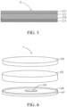
FIG. 6 is a schematic cross-sectional view of the grinding disc provided by a fourth embodiment of the present application; and -
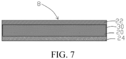
FIG. 7 is a schematic cross-sectional view of the grinding disc provided by a fifth embodiment of the present application. - The technical solution in the embodiment of the present application will be clearly and completely described below with reference to the accompanying drawings in the embodiments of the present application. Apparently, the described embodiments are merely some embodiments of the present application instead of all embodiments. According to the embodiments in the present application, all other embodiments obtained by those skilled in the art without making any creative effort shall fall within the protection scope of the present application.
- In the description of the present application, it should be understood that terminologies "longitudinal", "transverse", "length", "width", "thickness", "upper", "lower", "front", "rear", "left", "side", "vertical", "horizontal" for indicating relations of orientation or position are based on orientation or position of the accompanying drawings, are only for the purposes of facilitating description of the present application and simplifying the description instead of indicating or implying that the referred device or element must have a specific orientation or position, must to be structured and operated with the specific orientation or position. Therefore, they should not be understood as limitations to the present application. Furthermore, terminologies "first", "second" are only for the purposes of description, and cannot be understood as indication or implication of comparative importance or a number of technical features. Therefore, a feature limited with "first", "second" can expressly or implicitly include one or more features. In the description of the present application, a meaning of "a plurality of" is two or more, unless there is a clear and specific limitation otherwise.
- The present application may repeat reference numerals and/or reference letters in different examples. The repetition is for the purpose of simplification and clarity, and does not by itself indicate the relationship between the various embodiments and/or settings discussed.
- The display panel of the present application are described in detail in combination with specific embodiments as follows.
- With reference to
FIGs. 1 to 2 , asubstrate cleaning device 100 comprises: a grinding head 1 and agrinding disc 2 disposed at an end of the grinding head 1. Thegrinding disc 2 comprises a thickness self-adaptive layer 20 and abase layer 22 and a grindingplate 24 that are located on two opposite surfaces of the thickness self-adaptive layer 20. Thegrinding disc 2 is fixed to the grinding head 1 through thebase layer 22. Therefore, a hardness of thebase layer 22 is required to be excellent to prevent deformation. The thickness self-adaptive layer 20 has flexibility and can deform based on a pressure applied by the grindingdisc 2 to a product to be cleaned 103 such that thegrinding disc 2 completely fits a surface of the product to be cleaned 103. - The
grinding disc 2 is detachably fixed to the grinding head 1. For example, vacuum attachment, magnetic attachment or double-sided tap adhesion can be adopted. Preferably, vacuum attachment is used for fixing to prevent residue of glue remains when thegrinding disc 2 is removed and influence later cleaning effect. - In the present embodiment, thickness and material of the hard material layer has no specific requirement, any materials without deformation can be applied. For example, resin material, metal material, etc.
- A thickness of the grinding
plate 24 is less than a thickness of the thickness self-adaptive layer 20. An objective of such design is to make thegrinding disc 2 to adapt for stretch and retraction variations of the foam. In the present embodiment, a thickness range of the grindingplate 24 is 0.5mm-1mm, and preferably is 0.5 millimeters, which can be adapted for a certain compression deformation of foam. - The grinding
plate 24 can be selected from materials of aluminum oxide, cerium oxide, and silicon oxide. In the present embodiment, a material of the grindingplate 24 is aluminum oxide. The grindingplate 24 manufactured by the above can fulfill grinding hardness requirements and prevention of dregs. - In other embodiment, the grinding
plate 24 can also be selected from materials of substances with greater hardness and magnetic. - A thickness range of the thickness self-
adaptive layer 20 is 4 to 5 millimeters. A hardness range of the thickness self-adaptive layer 20 is 30HRC-40HRC. Preferably, the hardness range of the thickness self-adaptive layer 20 is 35HRC. The thickness self-adaptive layer 20 which is over hard would result in poor scalability to fail to reach self-adaptive requirements, and the thickness self-adaptive layer 20 which is over soft would result in excessive deformation of the grindingplate 24 to wear acarrier stage 101 for carrying a product. - The thickness self-
adaptive layer 20 is configured to deform based on pressure, and a material of the thickness self-adaptive layer 20 is foam, a foam pad, or a resilient element formed b a spring. Of course, other structure or material that can deform according to an external force and can restore from deformation after the external force is removed, with hardness of 30 to 40 degrees to achieve a thickness adjustment, can be applied. In the present embodiment, the thickness self-adaptive layer 20 is foam, for example, fiber foam, strip foam, or pure color foam. - In the present embodiment, the grinding
plate 24 and the thickness self-adaptive layer 20 are fixed to each other through super glue, and the thickness self-adaptive layer 20 and thebase layer 22 are fixed to each other through super glue. - In some of the embodiments, the
base layer 22, a diameter of the thickness self-adaptive layer 20 is the same as a diameter of of the grindingplate 24diameter, and the
grinding disc 2 is circular or rectangular. In the present embodiment, the grindingdisc 2 is circular. - The
substrate cleaning device 100 is configured to be disposed on thecarrier stage 101. A product to be cleaned 103 with a thickness of 0.7mm can have grinding parameters as follows: A driving end is activated such that a height H of the grindingplate 24 from thecarrier stage 101 is about 0.3 millimeters, and then a downward compression amount of the grinding disc 2 (a deformation amount of the thickness self-adaptive layer 20) is 0.2 to 0.4 millimeters, and a pressure of a grinding pneumatic cylinder is 0.16 to 0.2Mpa, a rotation speed of the grinding head is 150 to 250 r/s. After a final check, the grindingdisc 2 can completely contact the product and an effective cleaning area of thegrinding disc 2 can reach 100%, which drastically enhances a yield rate. - With reference to
FIGs. 3 to 4 , a structure of thegrinding disc 4 provided byFIGs. 3 to 4 is basically the same as a structure of thegrinding disc 2 provided by the first embodiment, and a difference of thegrinding disc 4 inFIGs. 3 to 4 is that: Ametal pad 26 is further disposed between the thickness self-adaptive layer 20 and the grindingplate 24. A center of themetal pad 26 coincides with a center of the grindingplate 24 and a center of the thickness self-adaptive layer 20, and a dimeter of themetal pad 26 is less than a diameter of the grindingplate 24. - An objective of disposing the
metal pad 26 is as follows: During a grinding process of a small size product such as a wafer, a size of thegrinding disc 2 is larger than a size of the product such that an edge of the grindingplate 24 receives a great force and results in a center of thegrinding disc 2 is slightly higher than a periphery of thegrinding disc 2 such that a substrate covered by the center portion cannot be completely grinded. Adding a layer of themetal pad 26 between thickness self-adaptive layer 20 and the grindingplate 24 would increase an amount of intervening compression of thegrinding disc 2 to enhance cleaning effect. - In the present embodiment, a ratio of the diameter of the
metal pad 26 to the diameter of the grindingplate 24 is between one-fifth to one-fourth. A thickness range of themetal pad 26 is 0.2-0.3 millimeters. - For example, In the present embodiment, the diameter of the grinding plate is 13 centimeters, and the diameter of the metal pad is 3 centimeters .
- In the present embodiment, the grinding
plate 24 is a magnetic metal material, themetal pad 26 and the grindingplate 24 are attached and fixed to each other magnetically. As such, contacting surfaces of themetal pad 26 and the grindingplate 24 completely fit each other. In one hand, themetal pad 26 can be used to reinforced a strength of the grindingplate 24. On the other hand, positions of both can be fixed securely to prevent displacement of themetal pad 26 affecting the cleaning effect. - With reference to
FIG. 5 , a structure of the grinding disc 6 provided byFIG. 5 is basically the same as the structure of thegrinding disc 2 provided by the first embodiment, and a difference of the grinding disc 6 inFIG. 5 is that: Aflange 28 is formed on a periphery of the grindingplate 24, and a height of theflange 28 is less than the thickness of the thickness self-adaptive layer 20 when a deformation amount of the thickness self-adaptive layer 20 is maximum. The thickness self-adaptive layer 20 is disposed in an accommodation recess formed by theflange 28 and an upper surface of the grindingplate 24. In a preferred embodiment, a height range of theflange 28 is 1.5 to 2.5 millimeters. - An objective of disposing the
flange 28 is as follows: Because during the grinding and cleaning process, deionized water is sprayed on a surfacer of the substrate, and theflange 28 is utilized to prevent sewage such as the deionized water from entering the thickness self-adaptive layer 20 from a circumference surface of the thickness self-adaptive layer 20. The height of theflange 28 less than the thickness of the thickness self-adaptive layer 20 when the deformation amount of the thickness self-adaptive layer is maximum, is for not influencing a self-adaptive characteristic of the thickness self-adaptive layer 20 such that the thickness self-adaptive layer 20 can excellently fit the surface of the product to achieve a capability of completely cleaning the surface of the product. - With reference to
FIG. 6 , a structure of thegrinding disc 7 provided byFIG. 6 is basically the same as the structure of the grinding disc 6 provided byFIG. 5 , and a difference of thegrinding disc 7 inFIG. 6 is as follows: Ametal pad 26 is fixed on the grindingplate 24 to increase an amount of intervening compression of thegrinding disc 2 and also to increase a contact area between the grinding disc 6 and the product to improve cleaning effect. - With reference to
FIG. 7 , a structure of the grinding disc 8 provided byFIG. 7 is basically the same as the structure of the structure of thegrinding disc 2 provided by the first embodiment, and a difference of the grinding disc 8 provided byFIG. 7 is as follows: A water-proof coating layer 30 is disposed on a circumference surface of the thickness self-adaptive layer 20, and the water-proof coating layer 30 is used to completely seal a small hole with of the circumference surface of the thickness self-adaptive layer 20. - An objective of disposing the water-proof coating layer 30 is as follows: Because during the grinding and cleaning process, deionized water is sprayed on the surface of the substrate, the water-proof coating layer 30 is utilized to prevent sewage such as deionized water from entering the thickness self-
adaptive layer 20 through the circumference surface of the thickness self-adaptive layer 20. - Of course, it can be understood that in the present embodiment, the
metal pad 26 can also be added between the thickness self-adaptive layer 20 and the grindingplate 24. - As described above, advantages of the present application are as follows: The
substrate cleaning device 100 provided by the present application disposes a thickness self-adaptive layer 20 on an end of a grindingplate 24 away from a grinding surface to make the thickness self-adaptive layer 20 able to deform based on a pressure applied by the grindingdisc 2 to a product to be cleaned 103 such that thegrinding disc 2 can complete fit a surface of the product to be cleaned 103 to increase a contact area between the grindingplate 24 and the product to be cleaned 103, which overcomes blind spots of cleaning due to thenon-parallel grinding plate 24 and product, improves cleaning effect, and drastically enhances a product rate. - For a condition that the size of the
grinding disc metal pad 26 is added between the thickness self-adaptive layer 20 and the grindingplate 24, which can increase an amount of intervening compression of thegrinding disc - Although the preferred embodiments of the present invention have been disclosed as above, the aforementioned preferred embodiments are not used to limit the present invention. The person of ordinary skill in the art may make various changes and modifications without departing from the spirit and scope of the present invention. Therefore, the scope of protection of the present invention is defined by the scope of the claims.
Claims (20)
- A grinding disc, wherein the grinding disc comprises:a base layer;a thickness self-adaptive layer disposed on the base layer, wherein the thickness self-adaptive layer is configured to deform based on pressure; anda grinding plate disposed on a side of the thickness self-adaptive layer away from the base layer, wherein the grinding plate is adapted for contacting a product to grind and clean the product.
- The grinding disc according to claim 1, wherein a thickness range of the thickness self-adaptive layer is 4 to 5 millimeters, and a hardness range of the thickness self-adaptive layer is 30HRC-40HRC.
- The grinding disc according to claim 1, wherein a thickness range of the grinding plate is 0.5 to 1 millimeter.
- The grinding disc according to claim 1, wherein a metal pad is disposed between the thickness self-adaptive layer and the grinding plate, a center of the metal pad coincides with a center of the grinding plate and a center of the thickness self-adaptive layer, and a diameter of the metal pad is less than a diameter of the grinding plate.
- The grinding disc according to claim 4, wherein a ratio of the diameter of the metal pad to the diameter of the grinding plate is between one-fifth to one-fourth.
- The grinding disc according to claim 4, wherein a thickness range of the metal pad is 0.2 to 0.3 millimeters.
- The grinding disc according to claim 1, wherein a material of the thickness self-adaptive layer is foam or foam pad.
- The grinding disc according to claim 1, wherein a water-proof material layer is disposed on a periphery of the thickness self-adaptive layer.
- The grinding disc according to claim 1, wherein a flange is disposed on a periphery of the grinding plate, and a height of the flange is less than a thickness of the thickness self-adaptive layer when a deformation amount of the thickness self-adaptive layer is maximum.
- A substrate cleaning device, comprising a grinding head and a grinding disc connected to the grinding head, wherein the grinding disc comprises:a base layer;a thickness self-adaptive layer disposed on the base layer, wherein the thickness self-adaptive layer is configured to deform based on pressure; anda grinding plate disposed on a side of the thickness self-adaptive layer away from the base layer, wherein the grinding plate is adapted for contacting a product to grind and clean the product.
- The substrate cleaning device according to claim 10, wherein a thickness range of the thickness self-adaptive layer is 4 to 5 millimeters, and a hardness range of the thickness self-adaptive layer is 30HRC-40HRC.
- The substrate cleaning device according to claim 10, wherein a thickness range of the grinding plate is 0.5 to 1 millimeter.
- The substrate cleaning device according to claim 10, wherein a metal pad is disposed between the thickness self-adaptive layer and the grinding plate, a center of the metal pad coincides with a center of the grinding plate and a center of the thickness self-adaptive layer, and a diameter of the metal pad is less than a diameter of the grinding plate.
- The substrate cleaning device according to claim 13, wherein the grinding plate is a magnetic metal material, and the metal pad and the grinding plate are attached and fixed to each other magnetically.
- The substrate cleaning device according to claim 13, wherein a ratio of the diameter of the metal pad to the diameter of the grinding plate is between one-fifth to one-fourth.
- The substrate cleaning device according to claim 13, wherein a thickness range of the metal pad is 0.2 to 0.3 millimeters.
- The substrate cleaning device according to claim 10, wherein a material of the thickness self-adaptive layer is foam or foam pad.
- The substrate cleaning device according to claim 10, wherein a water-proof material layer is disposed on a periphery of the thickness self-adaptive layer.
- The substrate cleaning device according to claim 10, wherein a flange is disposed on a periphery of the grinding plate, and a height of the flange is less than a thickness of the thickness self-adaptive layer when a deformation amount of the thickness self-adaptive layer is maximum.
- The substrate cleaning device according to claim 10, wherein the grinding head is detachably connected to the grinding disc.
Applications Claiming Priority (2)
| Application Number | Priority Date | Filing Date | Title |
|---|---|---|---|
| CN202110965606.9A CN113714928B (en) | 2021-08-23 | 2021-08-23 | Grinding disc and substrate cleaning device |
| PCT/CN2021/118207 WO2023024190A1 (en) | 2021-08-23 | 2021-09-14 | Grinding disk and substrate cleaning device |
Publications (3)
| Publication Number | Publication Date |
|---|---|
| EP4393645A1 true EP4393645A1 (en) | 2024-07-03 |
| EP4393645A4 EP4393645A4 (en) | 2025-07-09 |
| EP4393645B1 EP4393645B1 (en) | 2026-01-28 |
Family
ID=78677349
Family Applications (1)
| Application Number | Title | Priority Date | Filing Date |
|---|---|---|---|
| EP21916650.1A Active EP4393645B1 (en) | 2021-08-23 | 2021-09-14 | Grinding disk and substrate cleaning device |
Country Status (6)
| Country | Link |
|---|---|
| US (1) | US20240042572A1 (en) |
| EP (1) | EP4393645B1 (en) |
| JP (1) | JP7541079B2 (en) |
| KR (1) | KR102731423B1 (en) |
| CN (1) | CN113714928B (en) |
| WO (1) | WO2023024190A1 (en) |
Family Cites Families (23)
| Publication number | Priority date | Publication date | Assignee | Title |
|---|---|---|---|---|
| JPS56116155U (en) * | 1980-02-08 | 1981-09-05 | ||
| JPH0691545A (en) * | 1992-09-17 | 1994-04-05 | Toshiba Corp | Polishing tool |
| US7141146B2 (en) * | 2000-02-23 | 2006-11-28 | Asm Nutool, Inc. | Means to improve center to edge uniformity of electrochemical mechanical processing of workpiece surface |
| JP2004524676A (en) | 2000-12-27 | 2004-08-12 | ラム リサーチ コーポレーション | Method for manufacturing reinforced wafer polishing pad and apparatus mounting the pad |
| TW493486U (en) * | 2000-12-29 | 2002-07-01 | Basso Ind Corp | Improved structure of dust shielding ring of penumatic grinder |
| CN100467220C (en) * | 2006-12-01 | 2009-03-11 | 刘小辉 | Method for eliminating arc surface deformation of polished tiles and polishing machine suitable for the method |
| JP2008290207A (en) * | 2007-05-25 | 2008-12-04 | Mitsubishi Materials Techno Corp | Polishing machine |
| JP2010264567A (en) * | 2009-05-15 | 2010-11-25 | Mitsubishi Materials Corp | Pad conditioner |
| DE102009030298B4 (en) * | 2009-06-24 | 2012-07-12 | Siltronic Ag | Process for local polishing of a semiconductor wafer |
| KR20110008979U (en) * | 2010-03-15 | 2011-09-21 | 엠.씨.케이 (주) | Polishing pad |
| JP5789870B2 (en) * | 2011-09-14 | 2015-10-07 | 東邦エンジニアリング株式会社 | Auxiliary plate and polishing apparatus for polishing pad having anti-soaking structure |
| JP6295807B2 (en) * | 2014-04-28 | 2018-03-20 | 株式会社リコー | Polishing tool and polishing apparatus |
| MY186275A (en) * | 2016-08-23 | 2021-07-02 | Shinetsu Chemical Co | Method for producing substrate |
| TWM536130U (en) * | 2016-09-02 | 2017-02-01 | Chi-Tong Gong | Grinding pad structure with high grinding effect |
| CN107309785B (en) * | 2017-07-28 | 2019-03-19 | 义乌市台荣超硬制品有限公司 | A kind of Circular back-plate for carrying flexible abrasive material structure |
| JP6989361B2 (en) * | 2017-11-22 | 2022-01-05 | 日本特殊陶業株式会社 | Substrate adsorption member and its manufacturing method |
| CN207724096U (en) * | 2017-12-14 | 2018-08-14 | 东莞市亚马电子有限公司 | Cerium oxide grinding disc for cleaning and polishing |
| CN108161711A (en) * | 2017-12-28 | 2018-06-15 | 德淮半导体有限公司 | Grinding wafer device and grinding head |
| CN209256645U (en) * | 2018-02-26 | 2019-08-16 | 凯斯科技股份有限公司 | Substrate board treatment |
| CN208342544U (en) * | 2018-06-28 | 2019-01-08 | 河北思瑞恩新材料科技有限公司 | A kind of automatically cleaning buffering abrasive disk |
| CN208528802U (en) * | 2018-08-01 | 2019-02-22 | 成都市明峰光学仪器有限公司 | A kind of upper millstone device for wafer lapping machine |
| CN113070810A (en) * | 2020-01-03 | 2021-07-06 | 铨科光电材料股份有限公司 | Wafer polishing pad |
| CN111941155A (en) * | 2020-08-13 | 2020-11-17 | 蚌埠中光电科技有限公司 | Grinding pad processing method for eliminating grinding trace of glass surface |
-
2021
- 2021-08-23 CN CN202110965606.9A patent/CN113714928B/en active Active
- 2021-09-14 EP EP21916650.1A patent/EP4393645B1/en active Active
- 2021-09-14 JP JP2022515749A patent/JP7541079B2/en active Active
- 2021-09-14 WO PCT/CN2021/118207 patent/WO2023024190A1/en not_active Ceased
- 2021-09-14 KR KR1020227002666A patent/KR102731423B1/en active Active
- 2021-09-14 US US17/594,027 patent/US20240042572A1/en not_active Abandoned
Also Published As
| Publication number | Publication date |
|---|---|
| CN113714928A (en) | 2021-11-30 |
| JP7541079B2 (en) | 2024-08-27 |
| CN113714928B (en) | 2023-05-05 |
| KR102731423B1 (en) | 2024-11-19 |
| EP4393645A4 (en) | 2025-07-09 |
| KR20230031179A (en) | 2023-03-07 |
| JP2023542258A (en) | 2023-10-06 |
| US20240042572A1 (en) | 2024-02-08 |
| EP4393645B1 (en) | 2026-01-28 |
| WO2023024190A1 (en) | 2023-03-02 |
Similar Documents
| Publication | Publication Date | Title |
|---|---|---|
| KR101627897B1 (en) | Method for polishing a semiconductor wafer | |
| US6827638B2 (en) | Polishing device and method | |
| TWI403386B (en) | Abrasive pad and grinding device | |
| EP2898987A1 (en) | Grinding material product with concave-convex structure and preparation method thereof | |
| TWI614801B (en) | Wafer double-sided polishing method | |
| CN202725449U (en) | Photoresist spinner for silicon wafer | |
| CN202702052U (en) | Composite and elastic grinding and polishing disc with hierarchical structure | |
| US20240042572A1 (en) | Grinding disc and substrate cleaning device | |
| TW202302274A (en) | Static pressure plate of silicon wafer double-sided grinding device and silicon wafer double-sided grinding device | |
| TW201233537A (en) | Laminated structure and method for producing processed product | |
| CN109130454A (en) | A kind of the adhesive tape attaching method and screen printing screens of screen printing screens | |
| JP3749909B2 (en) | Method for polishing glass plate surface, glass substrate for flat panel display, and flat panel display | |
| US6712673B2 (en) | Polishing apparatus, polishing head and method | |
| EA050789B1 (en) | GRINDING WHEEL AND SUBSTRATE CLEANING DEVICE | |
| CN112091811A (en) | Carrier and method for manufacturing substrate using the same | |
| CN111941155A (en) | Grinding pad processing method for eliminating grinding trace of glass surface | |
| JP2005350350A (en) | Method for polishing glass plate surface, glass substrate for flat panel display, and flat panel display | |
| KR100931197B1 (en) | Head Assembly for Wafer Polishing Machine | |
| KR101334012B1 (en) | Manufacturing method of substrate for mask blank, and manufacturing method of mask blank and mask | |
| US11541505B2 (en) | Polishing pad, manufacturing method of polishing pad and polishing method | |
| WO2018116690A1 (en) | Single-wafer one-side polishing method for silicon wafer | |
| CN115056045B (en) | Wafer single-sided polishing device and method | |
| CN211073145U (en) | A kind of blue glass thickness dual-purpose polishing pad | |
| CN214351353U (en) | Glass sheet polishing equipment | |
| CN215947397U (en) | Ceramic hole plate for gold bump manufacturing sputtering machine |
Legal Events
| Date | Code | Title | Description |
|---|---|---|---|
| STAA | Information on the status of an ep patent application or granted ep patent |
Free format text: STATUS: UNKNOWN |
|
| STAA | Information on the status of an ep patent application or granted ep patent |
Free format text: STATUS: THE INTERNATIONAL PUBLICATION HAS BEEN MADE |
|
| PUAI | Public reference made under article 153(3) epc to a published international application that has entered the european phase |
Free format text: ORIGINAL CODE: 0009012 |
|
| STAA | Information on the status of an ep patent application or granted ep patent |
Free format text: STATUS: REQUEST FOR EXAMINATION WAS MADE |
|
| 17P | Request for examination filed |
Effective date: 20220714 |
|
| AK | Designated contracting states |
Kind code of ref document: A1 Designated state(s): AL AT BE BG CH CY CZ DE DK EE ES FI FR GB GR HR HU IE IS IT LI LT LU LV MC MK MT NL NO PL PT RO RS SE SI SK SM TR |
|
| DAV | Request for validation of the european patent (deleted) | ||
| DAX | Request for extension of the european patent (deleted) | ||
| REG | Reference to a national code |
Ref country code: DE Ref legal event code: R079 Free format text: PREVIOUS MAIN CLASS: B24B0037110000 Ipc: B24B0027033000 Ref country code: DE Ref legal event code: R079 Ref document number: 602021047381 Country of ref document: DE Free format text: PREVIOUS MAIN CLASS: B24B0037110000 Ipc: B24B0027033000 |
|
| A4 | Supplementary search report drawn up and despatched |
Effective date: 20250606 |
|
| RIC1 | Information provided on ipc code assigned before grant |
Ipc: B24D 3/00 20060101ALI20250602BHEP Ipc: B24B 37/24 20120101ALI20250602BHEP Ipc: B24B 7/22 20060101ALI20250602BHEP Ipc: B24B 27/033 20060101AFI20250602BHEP |
|
| REG | Reference to a national code |
Ref country code: DE Ref legal event code: R079 Free format text: PREVIOUS MAIN CLASS: B24B0027033000 Ipc: B24D0013140000 Ref country code: DE Ref legal event code: R079 Ref document number: 602021047381 Country of ref document: DE Free format text: PREVIOUS MAIN CLASS: B24B0027033000 Ipc: B24D0013140000 |
|
| GRAP | Despatch of communication of intention to grant a patent |
Free format text: ORIGINAL CODE: EPIDOSNIGR1 |
|
| STAA | Information on the status of an ep patent application or granted ep patent |
Free format text: STATUS: GRANT OF PATENT IS INTENDED |
|
| RIC1 | Information provided on ipc code assigned before grant |
Ipc: B24D 13/14 20060101AFI20251027BHEP |
|
| INTG | Intention to grant announced |
Effective date: 20251110 |
|
| GRAS | Grant fee paid |
Free format text: ORIGINAL CODE: EPIDOSNIGR3 |
|
| GRAA | (expected) grant |
Free format text: ORIGINAL CODE: 0009210 |
|
| STAA | Information on the status of an ep patent application or granted ep patent |
Free format text: STATUS: THE PATENT HAS BEEN GRANTED |
|
| AK | Designated contracting states |
Kind code of ref document: B1 Designated state(s): AL AT BE BG CH CY CZ DE DK EE ES FI FR GB GR HR HU IE IS IT LI LT LU LV MC MK MT NL NO PL PT RO RS SE SI SK SM TR |
|
| P01 | Opt-out of the competence of the unified patent court (upc) registered |
Free format text: CASE NUMBER: UPC_APP_0018457_4393645/2025 Effective date: 20251219 |
|
| REG | Reference to a national code |
Ref country code: CH Ref legal event code: F10 Free format text: ST27 STATUS EVENT CODE: U-0-0-F10-F00 (AS PROVIDED BY THE NATIONAL OFFICE) Effective date: 20260128 Ref country code: GB Ref legal event code: FG4D |
|
| REG | Reference to a national code |
Ref country code: DE Ref legal event code: R096 Ref document number: 602021047381 Country of ref document: DE |
|
| REG | Reference to a national code |
Ref country code: IE Ref legal event code: FG4D |