EP4392330B1 - Equipement spatial thermorégulé à soutien mécanique thermiquement isolant - Google Patents
Equipement spatial thermorégulé à soutien mécanique thermiquement isolant Download PDFInfo
- Publication number
- EP4392330B1 EP4392330B1 EP23729803.9A EP23729803A EP4392330B1 EP 4392330 B1 EP4392330 B1 EP 4392330B1 EP 23729803 A EP23729803 A EP 23729803A EP 4392330 B1 EP4392330 B1 EP 4392330B1
- Authority
- EP
- European Patent Office
- Prior art keywords
- interface
- mesh
- mechanical support
- equipment
- support structure
- Prior art date
- Legal status (The legal status is an assumption and is not a legal conclusion. Google has not performed a legal analysis and makes no representation as to the accuracy of the status listed.)
- Active
Links
Images




Classifications
-
- B—PERFORMING OPERATIONS; TRANSPORTING
- B64—AIRCRAFT; AVIATION; COSMONAUTICS
- B64G—COSMONAUTICS; VEHICLES OR EQUIPMENT THEREFOR
- B64G1/00—Cosmonautic vehicles
- B64G1/22—Parts of, or equipment specially adapted for fitting in or to, cosmonautic vehicles
- B64G1/66—Arrangements or adaptations of apparatus or instruments, not otherwise provided for
-
- B—PERFORMING OPERATIONS; TRANSPORTING
- B64—AIRCRAFT; AVIATION; COSMONAUTICS
- B64G—COSMONAUTICS; VEHICLES OR EQUIPMENT THEREFOR
- B64G1/00—Cosmonautic vehicles
- B64G1/22—Parts of, or equipment specially adapted for fitting in or to, cosmonautic vehicles
- B64G1/46—Arrangements or adaptations of devices for control of environment or living conditions
- B64G1/50—Arrangements or adaptations of devices for control of environment or living conditions for temperature control
-
- B—PERFORMING OPERATIONS; TRANSPORTING
- B64—AIRCRAFT; AVIATION; COSMONAUTICS
- B64G—COSMONAUTICS; VEHICLES OR EQUIPMENT THEREFOR
- B64G1/00—Cosmonautic vehicles
- B64G1/22—Parts of, or equipment specially adapted for fitting in or to, cosmonautic vehicles
- B64G1/52—Protection, safety or emergency devices; Survival aids
- B64G1/58—Thermal protection, e.g. heat shields
Definitions
- the present disclosure relates to an assembly comprising thermoregulated space equipment and one or more thermally insulating mechanical support structures.
- Spacecraft such as artificial satellites, probes, vessels, may include a payload comprising one or more items of equipment, such as optical instruments, telecommunications instruments, or sensors, and a platform on which the instruments are mounted, this platform in particular providing a mechanical support role.
- items of equipment such as optical instruments, telecommunications instruments, or sensors
- thermoregulated Some equipment, or some components of this equipment, must be thermoregulated to allow optimal operation. This is the case, for example, of a focal plane of an optical instrument, which may include detectors likely to experience an increase in temperature during image acquisition, this increase in temperature itself being able to disrupt the instrument and disrupt the quality of the images acquired.
- the support structure allowing to connect these equipments to the platform must satisfy both a requirement of high mechanical stiffness, to ensure a decoupling of the mechanical constraints that the platform could induce on the equipment, and on the other hand ensure a thermal insulation of the thermoregulated equipment with respect to the platform.
- the document CN 111 891 389 A discloses an assembly comprising thermoregulated space equipment and at least one mechanical support structure for the space equipment.
- This disclosure improves the situation.
- thermoregulated space equipment and at least one mechanical support structure comprising a first metal portion for interface with the equipment, secured to at least one second metal portion for interface with a space platform, said mechanical support structure further comprising at least one metal mesh forming a mechanical connection between said first and second interface portions, said mechanical support structure also comprising at least one block of mechanically rigid and thermally insulating material continuously and rigidly connecting said first and second interface portions and filling said metal mesh.
- the mesh comprises a three-dimensional arrangement of a plurality of rods connected together so as to form gaps therebetween.
- the assembly formed by the first interface portion, the second interface portion and the metal mesh is produced in a single block with at least one partition of the space equipment which extends by said first interface portion.
- the metal or metal alloy forming said mesh and said first and second interface portions on the one hand, and the block of thermally insulating material on the other hand have respective thermal expansion coefficients equal to at most 20%.
- the mesh and the first and second interface portions are formed from a titanium, aluminum and vanadium alloy or an iron and nickel alloy, for example composed of 64% iron and 36% nickel.
- the block of thermally insulating material is comprised of a ceramic or glass.
- the mechanical support structure defines a V-shaped foot where the tip of the V is extended by said first interface portion extended by two V-shaped metal meshes up to two second interface portions, the V-shaped meshes embedded at least partly in the block of thermally insulating material forming two mechanical connections between said first and second interface portions.
- the equipment is selected from an observation instrument and a cryostat.
- the proposed assembly comprises a mechanical support structure to meet requirements of high mechanical stiffness and thermal insulation of the equipment.
- the mechanical support structure comprises in this regard a block of thermally insulating material filling the interstices of a metal mesh.
- the metal mesh thus forms the core of the metal support structure, and makes it possible to define its shape.
- the assembly comprising the mesh and the interface portions can be produced by additive manufacturing, which makes it possible to produce a wide variety of shapes and dimensions. Furthermore, having a single-piece assembly comprising the mesh and the interface portions makes it possible to reduce the number of manipulations during assembly of the spacecraft.
- thermoregulated space equipment 10 may be, for example, an observation instrument, for example a telescope, comprising a thermoregulated component such as an optical detector or a focal plane.
- the space equipment may be any equipment subject to thermal regulation, for example a cryostat.
- thermoregulated space equipment 10 is embarked in a spacecraft comprising a support platform 20, being mounted on the support platform by means of at least one mechanical support structure 1.
- the spacecraft can for example be a satellite, a probe, a vessel, a space station, etc.
- the mechanical support structure 1 of the space equipment comprises at least a first interface portion 2 with the equipment 10, and at least a second interface portion 3 with the space platform 20.
- the two interface portions 2, 3 are made of metal or a metal alloy, for example titanium or a titanium-based alloy, such as for example an alloy based on titanium, aluminum and vanadium, or an iron and nickel alloy, for example an alloy consisting of 64% iron and 36% nickel known under the trade name Invar.
- the first and second interface portions 2, 3 are formed of the same metal or metal alloy.
- an interface portion 2,3 with the equipment or the space platform may comprise a plate comprising through holes allowing fixing by screws.
- an interface portion may be a part of a partition of the space equipment or a partition of the spacecraft carrying the equipment, said partition then being extended by the corresponding interface portion.
- the mechanical support structure 1 further comprises a metal mesh 4 establishing a mechanical connection between, on the one hand, the interface portion(s) 2 with the space equipment and, on the other hand, the interface portion(s) 3 with the platform.
- the metal mesh 4 may be made of the same metal or metal alloy as the interface portions 2, 3, and forms a mechanical connection between the first interface portion 2 and the second interface portion 3.
- the mesh 4 is advantageously made in one piece with the interface portions 2, 3, being devoid of a hinge.
- the single-piece assembly 9 is made in one piece with a partition of the space equipment.
- the mesh 4 comprises a three-dimensional arrangement of a set of rods 40 connected together so as to define between them interstices 41 which are also three-dimensional.
- These interstices 41 may have a geometric shape, for example be cubic, tetrahedral or hexahedral depending on the arrangement of the rods of the mesh, or else have a non-geometric and irregular shape.
- the dimension of the interstices of the mesh and the diameter of the rods may be variable depending on the size of the support structure, and the mechanical properties sought for this structure. For example, the length of an edge of a mesh cell may be between a few millimeters and a few centimeters.
- the shape of the mesh 4 can be variable depending on the number of interface portions 2,3 and the general geometry desired for the metal support structure.
- the mechanical support structure may comprise an interface portion 2 with the equipment 10 and an interface portion 3 with the space platform 20.
- the mesh 4 may extend in a substantially rectilinear manner between the two interface portions.
- the mechanical support structure 1 may comprise a single interface portion 2 with the equipment and two or three interface portions 3 with the space platform.
- the mesh can then have a general V or tripod shape comprising two - respectively three - rectilinear portions 4a, 4b, forming an angle between them, each rectilinear portion connecting together the interface portion 2 with the equipment and a respective interface portion 3a, 3b with the platform.
- the reverse configuration where the mechanical support structure comprises an interface portion 3 with the platform and two or more interfaces 2 with the equipment can also be envisaged.
- the structure can comprise several interface portions 2 with the equipment and several interface portions 3 with the platform and the mesh can have a cross shape.
- the mechanical support structure 1 of the space equipment also comprises a block 5 of mechanically rigid and thermally insulating material mechanically supporting the interface portions 2, 3 and filling the gaps in the mesh 4.
- the constituent material of the block is chosen to be able to be inserted into the metal mesh 4 in the powder state or in the liquid state to be able to be sintered or molded, as described in more detail below.
- the constituent material of the block is a ceramic, for example zirconia or glass, the latter being able for example to be of aluminate or silicate composition.
- the material is advantageously chosen to have a coefficient of thermal expansion close to that of the metal or metal alloy forming the single-piece assembly.
- the coefficients of thermal expansion of the cast material and of the material forming the single-piece assembly may be chosen to be equal to at most 20%, for example to at most 15%, or for example to at most 11%.
- the mechanical support structure(s) 1 can thus form the feet of a space equipment.
- the feet can be integrated into the space equipment or added.
- the feet integrated into the space equipment are for example made in the extension of a support wall or in the extension of a wall delimiting a closed space receiving a thermal regulation fluid.
- the example shown in the figure 1 is that of a structure comprising an interface portion with the equipment 10 and an interface portion with the platform 20, connected to each other by a linear mesh 4.
- the example shown in the figure 2 is that where the structure is a bipod comprising a portion 2 of interface with the equipment 10 and two portions 3a, 3b of interface with the platform.
- the mesh 4 connects the portion 2 with each portion 3a, 3b and has for this purpose a V shape comprising two rectilinear branches 4a, 4b joined at one end where they are integral with the portion 2, each branch being integral at its opposite end with a respective portion 3a, 3b.
- the block of material filling the mesh has the same shape.
- a thermoregulated space equipment 10 may comprise one or more mechanical support structures 1 obtained by the method described above, to connect it to the platform 20.
- the equipment may be supported by two mechanical support structures in the form of a bipod, as described above with reference to the figure 1 .
- a thermoregulated space equipment 10 may comprise a single mechanical support structure 1 in the form of a tripod comprising three legs connected together by one end formed by the portion 2 of interface with the equipment, the opposite ends of the three legs being formed by three respective portions of interface with the platform.
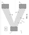
- Such a method comprises the provision 100 of a single-piece assembly 9 for defining the geometry of the mechanical support structure, an example of which is schematically shown in FIG. Figure 3a .
- This single-piece assembly comprises the first interface portion(s) 2 with the equipment 10, the second interface portion(s) 3 with the space platform 20, and the metal mesh 4 connecting said portions together.
- an interface portion may be a part of a partition of the space instrument or a partition of the spacecraft carrying the instrument, said partition then being extended by the corresponding interface portion.
- a first interface portion 2 with the instrument may be a part of a partition delimiting a cavity containing a material heat transfer medium providing thermal regulation of the instrument, such as a heat transfer structure with two-phase material, for example a heat pipe.
- the single-piece assembly 9 further comprises a mesh 4, also made of metal, which can be made of the same metal or metal alloy as the interface portions 2, 3, and forming a mechanical connection between the first interface portion 2 and the second interface portion 3.
- the mesh 4 is advantageously made in one piece with the interface portions 2, 3, being devoid of a hinge.
- the single-piece assembly 9 is made in one piece with a partition of the space instrument.
- the assembly comprising the interface portions 2, 3, and the metal mesh 4 forms a assembly 9 for defining the geometry of the mechanical support structure 1, because the geometry of the mesh, in particular its width and its depth between two interface portions, and the geometry and the relative positions of the interface portions, define the geometry of the structure obtained at the end of the process.
- This single-piece assembly 9 is advantageously made of a single metal part. It can be manufactured by additive manufacturing, for example during a preliminary step 90 of the process.
- the method then comprises the manufacture of the block 5 of mechanically rigid and thermally insulating material filling the interstices of the mesh 4.
- this step can be carried out by casting the constituent material of the molten block into the mesh, for example glass.
- the method then comprises a step 200 of casting the molten material into the metal mesh and against the first 2 and second 3 interface portions.
- the material in this case is chosen to have, in the molten state, a viscosity that is low enough to allow it to fill the interstices of the mesh and to form a mechanically rigid block once cooled.
- the size of the interstices of the mesh is also determined as a function of the material that is then cast in the molten state into the interstices of the mesh so as to fill these interstices, and of the technique used to carry out the casting.
- the cast material takes the form of a block 5 of mechanically rigid and thermally insulating material, resting against the interface portions and filling the mesh, that is to say at least partially filling the interstices of the mesh.
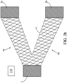
- Casting 200 may include, with reference to the figure 3b , a preliminary step 210 of positioning the single-piece assembly in a mold 6, the walls of which delimit the outline of the mechanical support structure to be produced, and more precisely the outlines of the block of material 5.
- the walls of the mold bear against the interface portions 2, 3 and extend around the outer outline of the mesh 4.
- the shape of the block of material 5 delimited by the mold corresponds to that of the mesh.
- the block of material also has a V shape with two rectilinear portions 5a, 5b connecting the interface portion 2 with each portion 3a, 3b respectively.
- the walls of the mold can however be spaced from the external contour of the mesh, for example by a distance less than or equal to the length of the edges of the mesh, which corresponds once the material has hardened to a circumferential portion around the mesh and devoid of rods of the mesh.
- the single-piece assembly 9, and where appropriate the mold in which it is placed for the purpose of casting the glass, are furthermore heated 220 in an oven, to a temperature lower than that of the melting of the glass, but preferably greater than or equal to the glass transition temperature of the glass, for example between 500 and 600°C, for example at 550°C.
- This heating step makes it possible to reduce the thermal shock between the glass and the single-piece assembly during casting and thus allow the glass to penetrate and fill all of the interstices of the mesh.
- the glass after synthesis and cooling, is preferably refined before being cast, that is to say it is heated 230 to be freed from the air bubbles that it may contain, and also to make it liquid in order to be cast.
- This step of refining and melting the glass can be carried out for example in another furnace at a temperature higher than 800°C, for example 1000°C or more.
- the actual pouring of the molten glass into the monobloc assembly can be carried out by gravity or by injection 240, after having removed the glass on the one hand, and the monobloc assembly on the other hand from their respective furnaces.
- This step is shown schematically in figure 3c .
- the structure comprising the monobloc assembly positioned in the mold and the glass filling the interstices of the mesh of the monobloc assembly are then replaced in an oven at the temperature of glass transition of the glass for mechanical annealing 250, allowing the stresses to be released.
- the duration of this annealing can be at least two hours.
- the process includes cooling the cast material 300 to obtain the rigid block.
- the structure is removed from the oven to gradually cool to room temperature.
- the mold can be before or after the temperature of the structure has reached room temperature.
- the structure obtained after removal of the mold is schematically shown in the 3d figure .
- the mechanical support structure 1 is obtained, exhibiting significant stiffness and enabling thermal insulation of the space equipment relative to the platform, due to the small relative surface area of the rods constituting the mesh relative to the block of thermally insulating material.
Landscapes
- Engineering & Computer Science (AREA)
- Aviation & Aerospace Engineering (AREA)
- Remote Sensing (AREA)
- General Health & Medical Sciences (AREA)
- Health & Medical Sciences (AREA)
- Emergency Medicine (AREA)
- Physics & Mathematics (AREA)
- Critical Care (AREA)
- Thermal Sciences (AREA)
- Life Sciences & Earth Sciences (AREA)
- Biodiversity & Conservation Biology (AREA)
- Environmental & Geological Engineering (AREA)
- Environmental Sciences (AREA)
- Toxicology (AREA)
- Thermal Insulation (AREA)
- Patch Boards (AREA)
- Casings For Electric Apparatus (AREA)
Description
- La présente divulgation concerne un ensemble comprenant un équipement spatial thermorégulé et une ou plusieurs structures de soutien mécanique thermiquement isolantes.
- Les engins spatiaux, tels que par exemple satellites artificiels, sondes, vaisseaux, peuvent comporter une charge utile comprenant un ou plusieurs équipements, comme des instruments optiques, des instruments de télécommunications, ou des capteurs, et une plate-forme sur laquelle sont montés les instruments, cette plate-forme assurant notamment un rôle de soutien mécanique.
- Certains équipements, ou certains composants de ces équipements, doivent être thermorégulés pour permettre un fonctionnement optimal. C'est le cas par exemple d'un plan focal d'instrument optique, pouvant comprendre des détecteurs susceptibles de subir un accroissement de température lors de l'acquisition d'images, cet accroissement de température pouvant lui-même dérégler l'instrument et perturber la qualité des images acquises.
- Pour ces équipements, la structure de soutien permettant de relier ces équipements à la plate-forme doit satisfaire à la fois une exigence de raideur mécanique élevée, pour assurer un découplage des contraintes mécaniques que pourrait induire la plate-forme sur l'équipement, et d'autre part assurer une isolation thermique de l'équipement thermorégulé par rapport à la plate-forme. On connaît notamment le brevet
FR3040777 - Ce type de technologie complexe est toutefois coûteux à fabriquer. Le document
CN 111 891 389 A divulgue un ensemble comprenant un équipement spatial thermorégulé et au moins une structure de soutien mécanique de l'équipement spatial. - La présente divulgation vient améliorer la situation.
- Il est proposé un ensemble comprenant un équipement spatial thermorégulé et au moins une structure de soutien mécanique comprenant une première portion métallique d'interface avec l'équipement, solidaire d'au moins une deuxième portion métallique d'interface avec une plateforme spatiale, ladite structure de soutien mécanique comprenant en outre au moins un maillage métallique formant une liaison mécanique entre lesdites première et deuxième portions d'interface, ladite structure de soutien mécanique comprenant également au moins un bloc de matériau mécaniquement rigide et thermiquement isolant reliant continûment et rigidement lesdites première et deuxième portions d'interface et comblant ledit maillage métallique.
- Dans des modes de réalisation, le maillage comprend un agencement en trois dimensions d'une pluralité de tiges reliées entre elles de façon à former entre elles des interstices.
- Dans des modes de réalisation, l'ensemble formé par la première portion d'interface, la deuxième portion d'interface et le maillage métallique est réalisé d'un seul bloc avec au moins une cloison de l'équipement spatial qui se prolonge par ladite première portion d'interface.
- Dans des modes de réalisation, le métal ou alliage métallique formant ledit maillage et lesdites première et deuxième portions d'interfaces d'une part, et le bloc de matériau thermiquement isolant d'autre part, présentent des coefficients de dilatation thermique respectifs égaux à au plus 20 % près.
- Dans des modes de réalisation, le maillage et les première et deuxième portions d'interfaces sont formés en alliage de titane, aluminium et vanadium ou en alliage de fer et nickel, par exemple composé à 64% de fer et 36% de nickel.
- Dans des modes de réalisation, le bloc de matériau thermiquement isolant est constitué par une céramique ou du verre.
- Dans des modes de réalisation, la structure de soutien mécanique définit un pied en V où la pointe du V est prolongée par ladite première portion d'interface prolongée par deux maillages métalliques en V jusqu'à deux deuxièmes portions d'interface, les maillages en V noyés au moins en partie dans le bloc de matériau thermiquement isolant formant deux liaisons mécaniques entre lesdites première et deuxièmes portions d'interface.
- Dans des modes de réalisation, l'équipement est choisi parmi un instrument d'observation et un cryostat.
- L'ensemble proposé comprend une structure de soutien mécanique permettant de satisfaire des exigences de raideur mécanique élevée et d'isolation thermique de l'équipement. La structure de soutien mécanique comprend à cet égard un bloc de matériau thermiquement isolant remplissant les interstices d'un maillage métallique. Le maillage métallique forme ainsi l'âme de la structure de soutien métallique, et permet de définir sa forme.
- Dans des modes de réalisation, l'ensemble comprenant le maillage et les portions d'interface peut être réalisé par fabrication additive, ce qui rend possible la réalisation d'une grande diversité de formes et de dimensions. Par ailleurs, le fait de disposer d'un ensemble monobloc incluant le maillage et les portions d'interface permet de diminuer le nombre de manipulation lors de l'assemblage de l'engin spatial.
- D'autres caractéristiques, détails et avantages apparaîtront à la lecture de la description détaillée ci-après, et à l'analyse des dessins annexés, sur lesquels :
-
Fig. 1
[Fig. 1 ] représente schématiquement un exemple de structure de soutien mécanique. -
Fig. 2
[Fig. 2 ] représente schématiquement un autre exemple de structure de soutien mécanique. -
Fig. 3a
[Fig. 3a ], représente schématiquement une étape de fourniture d'un ensemble monobloc d'un procédé de fabrication d'une structure de soutien mécanique. -
Fig. 3b
[Fig. 3b ] représente schématiquement une étape d'insertion du maillage de l'ensemble monobloc dans un moule lors d'un procédé de fabrication d'une structure de soutien mécanique. -
Fig. 3c
[Fig. 3c ] représente schématiquement une étape de coulage du matériau dans le maillage lors d'un procédé de fabrication d'une structure de soutien mécanique. -
Fig. 3d
[Fig. 3d ] représente schématiquement une étape de retrait de l'ensemble monobloc du moule et de refroidissement pour obtenir la structure de soutien mécanique. -
Fig. 4
[Fig. 4 ] représente schématiquement les principales étapes d'un procédé de fabrication d'une structure de soutien mécanique. -
Fig. 5
[Fig. 5 ] représente schématiquement un exemple d'application d'un dispositif de support comprenant des structures de soutien mécanique à un plan focal d'instrument spatial. - On va maintenant décrire des exemples d'un ensemble comprenant un équipement spatial 10 thermorégulé et une ou plusieurs structures de soutien mécanique 1. L'équipement spatial thermorégulé 10 peut être par exemple un instrument d'observation, par exemple un télescope, comprenant un composant thermorégulé tel qu'un détecteur optique ou un plan focal. Alternativement, l'équipement spatial peut être tout équipement faisant l'objet d'une régulation thermique, par exemple un cryostat.
- Cet équipement spatial thermorégulé 10 est embarqué dans un engin spatial comprenant une plateforme de support 20, en étant monté sur la plate-forme de support par l'intermédiaire d'au moins une structure de soutien mécanique 1. L'engin spatial peut par exemple être un satellite, une sonde, un vaisseau, une station spatiale, etc.
- La structure de soutien mécanique 1 de l'équipement spatial comprend au moins une première portion d'interface 2 avec l'équipement 10, et au moins une deuxième portion d'interface 3 avec la plate-forme spatiale 20. Les deux portions d'interface 2, 3 sont réalisées en métal ou en alliage métallique, par exemple du titane ou un alliage à base de titane, comme par exemple un alliage à base de titane, aluminium et vanadium, ou encore un alliage de fer et nickel, par exemple un alliage constitué à 64% de fer et 36% de nickel connu sous la dénomination commerciale Invar. Dans un mode de réalisation, les première et deuxième portions d'interface 2,3 sont formées du même métal ou alliage métallique.
- Dans un exemple de réalisation, une portion d'interface 2,3 avec l'équipement ou la plate-forme spatiale peut comprendre une platine comprenant des orifices traversants permettant une fixation par vis.
- Dans un exemple de réalisation, une portion d'interface peut être une partie d'une cloison de l'équipement spatial ou d'une cloison de l'engin spatial embarquant l'équipement, ladite cloison étant alors prolongée par la portion d'interface correspondante.
- La structure 1 de soutien mécanique comprend en outre un maillage métallique 4 établissant une liaison mécanique entre d'une part la ou les portions d'interface 2 avec l'équipement spatial et d'autre part la ou les portions d'interface 3 avec la plateforme. Le maillage métallique 4 peut être réalisé dans le même métal ou alliage métallique que les portions d'interface 2,3, et forme une liaison mécanique entre la première portion d'interface 2 et la deuxième portion d'interface 3. Le maillage 4 est avantageusement réalisé d'une seule pièce avec les portions d'interface 2,3, en étant dépourvu de charnière. Ainsi, dans un exemple de réalisation, l'ensemble monobloc 9 est réalisé d'une seule pièce avec une cloison de l'équipement spatial.
- Le maillage 4 comprend un agencement en trois dimensions d'un ensemble de tiges 40 reliées entre elles de façon à définir entre elles des interstices 41 également tridimensionnels. Ces interstices 41 peuvent présenter une forme géométrique, par exemple être cubiques, tétraédriques ou hexaédriques selon la disposition des tiges du maillage, ou encore présenter une forme non géométrique et irrégulière. La dimension des interstices du maillage et le diamètre des tiges peut être variable en fonction de la taille de la structure de support, et des propriétés mécaniques recherchées pour cette structure. Par exemple la longueur d'une arête d'une maille du maillage peut être comprise entre quelques millimètres et quelques centimètres.
- La forme du maillage 4 peut être variable en fonction du nombre de portions d'interface 2,3 et de la géométrie générale souhaitée pour la structure de soutien métallique. Dans un exemple illustré schématiquement sur la
figure 1 , la structure de soutien mécanique peut comprendre une portion d'interface 2 avec l'équipement 10 et une portion d'interface 3 avec la plate-forme spatiale 20. Dans ce cas, le maillage 4 peut s'étendre de façon sensiblement rectiligne entre les deux portions d'interface. En variante représentée sur lafigure 2 , la structure de soutien mécanique 1 peut comprendre une unique portion d'interface 2 avec l'équipement et deux ou trois portions d'interface 3 avec la plate-forme spatiale. Le maillage peut alors présenter une forme générale en V ou en trépied comprenant deux - respectivement trois - portions rectilignes 4a, 4b, formant un angle entre elles, chaque portion rectiligne reliant entre elles la portion d'interface 2 avec l'équipement et une portion d'interface 3a, 3b respective avec la plate-forme. La configuration inverse où la structure de soutien mécanique comprend une portion d'interface 3 avec la plate-forme et deux interfaces 2 ou plus avec l'équipement peut également être envisagée. Selon encore d'autres variantes, la structure peut comporter plusieurs portions d'interface 2 avec l'équipement et plusieurs portions d'interface 3 avec la plate-forme et le maillage peut présenter une forme de croix. - La structure de soutien mécanique 1 de l'équipement spatial comprend également un bloc 5 de matériau mécaniquement rigide et thermiquement isolant en appui mécanique contre les portions d'interface 2, 3 et comblant les interstices du maillage 4.
- Le matériau constitutif du bloc est choisi pour pouvoir être inséré dans le maillage métallique 4 à l'état de poudre ou à l'état liquide pour pouvoir être fritté ou moulé, comme décrit plus en détails ci-après. Dans des modes de réalisation, le matériau constitutif du bloc est une céramique, par exemple de la zircone ou du verre, ce dernier pouvant par exemple être à composition aluminate ou silicate.
- De plus, le matériau est avantageusement choisi pour présenter un coefficient de dilatation thermique proche de celui du métal ou de l'alliage métallique formant l'ensemble monobloc. Par exemple, mais non limitativement, les coefficients de dilatation thermique du matériau coulé et du matériau formant l'ensemble monobloc peuvent être choisis égaux à au plus 20%, par exemple à au plus 15% près, ou par exemple à au plus 11% près.
- La ou les structures de soutien mécanique 1 peut ainsi former les pieds d'un équipement spatial. Les pieds peuvent être intégrés à l'équipement spatial ou rapportés. Les pieds intégrés à l'équipement spatial sont par exemple réalisés dans le prolongement d'une paroi de support ou dans le prolongement d'une paroi délimitant un espace fermé recevant un fluide de régulation thermique.
- Deux exemples d'une telle structure de soutien mécanique 1 sont représentés sur la
figure 1 et lafigure 2 . - L'exemple représenté sur la
figure 1 est celui d'une structure comprenant une portion d'interface avec l'équipement 10 et une portion d'interface avec la plateforme 20, reliées entre elles par un maillage 4 linéaire. - L'exemple représenté sur la
figure 2 est celui où la structure est un bipode comprenant une portion 2 d'interface avec l'équipement 10 et deux portions 3a, 3b d'interface avec la plateforme. Le maillage 4 relie la portion 2 avec chaque portion 3a, 3b et présente à cet effet une forme en V comprenant deux branches 4a, 4b rectilignes unies à une extrémité où elles sont solidaires de la portion 2, chaque branche étant solidaire à son extrémité opposée d'une portion 3a, 3b respective. Le bloc de matériau comblant le maillage présente la même forme. - En référence à la
figure 5 , un équipement spatial thermorégulé 10 peut comprendre une ou plusieurs structures de soutien mécanique 1 obtenues par le procédé décrit ci-avant, pour le relier à la plateforme 20. Par exemple, l'équipement peut être supporté par deux structures de soutien mécanique sous forme de bipode, comme décrit ci-avant en référence à lafigure 1 . Selon un autre exemple, un équipement spatial thermorégulé 10 peut comprendre une unique structure de soutien mécanique 1 sous la forme de tripode comprenant trois pieds reliés entre eux par une extrémité formée par la portion 2 d'interface avec l'équipement, les extrémités opposées des trois pieds étant formées par trois portions respectives d'interface avec la plate-forme. - En référence aux
figures 3a à 3d et4 , on va décrire un exemple non limitatif de procédé de fabrication d'une structure de soutien mécanique 1 décrite ci-avant. Un tel procédé comprend la fourniture 100 d'un ensemble monobloc 9 de définition de la géométrie de la structure de soutien mécanique, dont un exemple est représenté schématiquement sur lafigure 3a . - Cet ensemble monobloc comprend la ou les première(s) portion(s) d'interface 2 avec l'équipement 10, la ou les deuxième(s) portion(s) d'interface 3 avec la plate-forme spatiale 20, et le maillage métallique 4 reliant entre elles lesdites portions.
- Dans un exemple de réalisation, une portion d'interface peut être une partie d'une cloison de l'instrument spatial ou d'une cloison de l'engin spatial embarquant l'instrument, ladite cloison étant alors prolongée par la portion d'interface correspondante. Par exemple, une première portion d'interface 2 avec l'instrument peut être une partie d'une cloison délimitant une cavité contenant un matériau caloporteur assurant une régulation thermique de l'instrument, comme par exemple une structure de transfert de chaleur a matériau diphasique, par exemple un caloduc.
- L'ensemble monobloc 9 comprend en outre un maillage également métallique 4, pouvant être réalisé dans le même métal ou alliage métallique que les portions d'interface 2,3, et formant une liaison mécanique entre la première portion d'interface 2 et la deuxième portion d'interface 3. Le maillage 4 est avantageusement réalisé d'une seule pièce avec les portions d'interface 2,3, en étant dépourvu de charnière. Ainsi, dans un exemple de réalisation, l'ensemble monobloc 9 est réalisé d'une seule pièce avec une cloison de l'instrument spatial.
- L'ensemble comprenant les portions d'interface 2, 3, et le maillage métallique 4 forme un ensemble 9 de définition de la géométrie de la structure de soutien mécanique 1, car la géométrie du maillage, en particulier sa largeur et sa profondeur entre deux portions d'interface, et la géométrie et les positions relatives des portions d'interface, définissent la géométrie de la structure obtenue à l'issue du procédé.
- Cet ensemble monobloc 9 est avantageusement d'une seule pièce métallique. Il peut être fabriqué par fabrication additive, par exemple lors d'une étape préliminaire 90 du procédé.
- Le procédé comprend ensuite la fabrication du bloc 5 de matériau mécaniquement rigide et thermiquement isolant remplissant les interstices du maillage 4.
- Dans un exemple de réalisation, cette étape peut être réalisée par coulage du matériau constitutif du bloc en fusion dans le maillage, par exemple du verre. Le procédé comprend alors une étape 200 de coulage du matériau en fusion dans le maillage métallique et contre les première(s) 2 et deuxième(s) 3 portions d'interface. Le matériau dans ce cas est choisi pour présenter, à l'état de fusion, une viscosité suffisamment faible pour lui permettre de remplir les interstices du maillage et pour former un bloc mécaniquement rigide une fois refroidi. La taille des interstices du maillage est également déterminée en fonction du matériau qui est ensuite coulé à l'état de fusion dans les interstices du maillage de façon à combler ces interstices, et de la technique utilisée pour procéder au coulage..
- Ainsi, après durcissement, le matériau coulé prend la forme d'un bloc 5 de matériau mécaniquement rigide et thermiquement isolant, en appui contre les portions d'interface et comblant le maillage, c'est-à-dire remplissant au moins en partie les interstices du maillage.
- Le coulage 200 peut comprendre, en référence à la
figure 3b , une étape préliminaire 210 de positionnement de l'ensemble monobloc dans un moule 6, dont les parois délimitent le contour de la structure de soutien mécanique à réaliser, et plus précisément les contours du bloc de matériau 5. Avantageusement, les parois du moule sont en appui contre les portions d'interface 2, 3 et s'étendent autour du contour extérieur du maillage 4. De fait, la forme du bloc de matériau 5 délimitée par le moule correspond à celle du maillage. Selon un exemple purement illustratif, et comme représenté sur lesfigures 3c et3d , si la structure à réaliser est un bipode, avec un maillage présentant une forme en V, le bloc de matériau présente également une forme en V avec deux portions rectilignes 5a, 5b reliant la portion d'interface 2 avec respectivement chaque portion 3a, 3b. Dans certains cas, les parois du moule peuvent cependant être espacées du contour extérieur du maillage, par exemple d'une distance inférieure ou égale à la longueur des arêtes du maillage, ce qui correspond une fois le matériau durci à une portion circonférentielle autour du maillage et dépourvue de tiges du maillage. - L'ensemble monobloc 9, et le cas échéant le moule dans lequel il est placé en vue du coulage du verre, sont par ailleurs chauffés 220 dans un four, à une température inférieure à celle de fusion du verre, mais de préférence supérieure ou égale à la température de transition vitreuse du verre, par exemple entre 500 et 600°C, par exemple à 550°C. Cette étape de chauffage permet de réduire le choc thermique entre le verre et l'ensemble monobloc lors du coulage et ainsi permettre que le verre pénètre et comble l'ensemble des interstices du maillage.
- Par ailleurs, le verre, après synthèse et refroidissement, est de préférence affiné avant d'être coulé, c'est-à-dire qu'il est chauffé 230 pour être débarrassé des bulles d'air qu'il peut contenir, et également pour le rendre liquide afin d'être coulé. Cette étape d'affinage et de fusion du verre peut être réalisée par exemple dans un autre four à une température supérieure à 800°C, par exemple de 1000°C ou plus.
- Le coulage proprement dit du verre en fusion dans l'ensemble monobloc peut être réalisé par gravité ou par injection 240, après avoir sorti le verre d'une part, et l'ensemble monobloc d'autre part de leurs fours respectifs. Cette étape est représentée schématiquement en
figure 3c . La structure comprenant l'ensemble monobloc positionné dans le moule et le verre comblant les interstices du maillage de l'ensemble monobloc sont ensuite replacés dans un four à la température de transition vitreuse du verre pour un recuit mécanique 250, permettant de relâcher les contraintes. La durée de ce recuit peut être d'au moins deux heures. - Puis le procédé comprend le refroidissement du matériau coulé 300 pour obtenir le bloc rigide. Pour cela, la structure est sortie du four pour refroidir progressivement à température ambiante. Le moule peut être avant ou après que la température de la structure a atteint la température ambiante. La structure obtenue après retrait du moule est représentée schématiquement sur la
figure 3d . - Une fois le matériau coulé durci, la structure de soutien mécanique 1 est obtenue, présentant une raideur importante et permettant d'assurer l'isolation thermique de l'équipement spatial par rapport à la plate-forme, du fait de la faible surface relative des tiges constitutives du maillage par rapport au bloc de matériau thermiquement isolant.
Claims (7)
- Ensemble comprenant un équipement spatial (10) thermorégulé et au moins une structure de soutien mécanique (1) de l'équipement spatial (10), la structure (1) comprenant une première portion (2) métallique d'interface avec l'équipement (10), solidaire d'au moins une deuxième portion (3) métallique d'interface avec une plateforme spatiale (20), ladite structure de soutien mécanique comprenant en outre au moins un maillage métallique (4) formant une liaison mécanique entre lesdites première et deuxième portions (2,3) d'interface, caractérisé en ce que ladite structure de soutien mécanique (1) comprend également au moins un bloc de matériau (5) mécaniquement rigide et thermiquement isolant reliant continûment et rigidement lesdites première et deuxième portions (2, 3) d'interface et comblant ledit maillage métallique.
- Ensemble selon la revendication 1, dans lequel ledit maillage (4) comprend un agencement en trois dimensions d'une pluralité de tiges (40) reliées entre elles de façon à former entre elles des interstices (41).
- Ensemble selon la revendication 1 ou 2, dans lequel l'ensemble formé par la première portion (2) d'interface, la deuxième portion (3) d'interface et le maillage métallique (4) est réalisé d'un seul bloc avec au moins une cloison de l'équipement spatial (10) qui se prolonge par ladite première portion d'interface (2).
- Ensemble selon l'une des revendications précédentes, où ledit maillage (4) et lesdites première (2) et deuxième (3) portions d'interfaces sont formés en alliage de titane, aluminium et vanadium ou en alliage de fer et nickel, par exemple composé à 64% de fer et 36% de nickel.
- Ensemble selon l'une des revendications précédentes, dans lequel le bloc de matériau mécaniquement rigide et thermiquement isolant (4) est constitué par une céramique ou du verre.
- Ensemble selon l'une des revendications précédente, dans lequel ladite structure de soutien mécanique (1) définit un pied en V où la pointe du V est prolongée par ladite première portion (2a) d'interface prolongée par deux maillages (5a, 5b) métalliques en V jusqu'à deux deuxièmes portions (3a, 3b) d'interface, les maillages en V noyés au moins en partie dans le bloc de matériau mécaniquement rigide et thermiquement isolant formant deux liaisons mécaniques entre lesdites première et deuxièmes portions d'interface.
- Ensemble selon l'une des revendications précédentes, l'équipement étant choisi parmi un instrument d'observation et un cryostat.
Applications Claiming Priority (2)
| Application Number | Priority Date | Filing Date | Title |
|---|---|---|---|
| FR2204638A FR3135451A1 (fr) | 2022-05-16 | 2022-05-16 | Equipement spatial thermorégulé à soutien mécanique thermiquement isolant |
| PCT/FR2023/050680 WO2023222966A1 (fr) | 2022-05-16 | 2023-05-12 | Equipement spatial thermorégulé à soutien mécanique thermiquement isolant |
Publications (2)
| Publication Number | Publication Date |
|---|---|
| EP4392330A1 EP4392330A1 (fr) | 2024-07-03 |
| EP4392330B1 true EP4392330B1 (fr) | 2024-12-18 |
Family
ID=82942758
Family Applications (1)
| Application Number | Title | Priority Date | Filing Date |
|---|---|---|---|
| EP23729803.9A Active EP4392330B1 (fr) | 2022-05-16 | 2023-05-12 | Equipement spatial thermorégulé à soutien mécanique thermiquement isolant |
Country Status (3)
| Country | Link |
|---|---|
| EP (1) | EP4392330B1 (fr) |
| FR (1) | FR3135451A1 (fr) |
| WO (1) | WO2023222966A1 (fr) |
Family Cites Families (8)
| Publication number | Priority date | Publication date | Assignee | Title |
|---|---|---|---|---|
| CN103241391B (zh) * | 2013-04-25 | 2016-03-16 | 上海卫星工程研究所 | 用于火星着陆器热控制的隔热组件及其制备方法 |
| FR3040777B1 (fr) | 2015-09-04 | 2019-04-19 | Thales | Ensemble de detection optique comportant un detecteur optique a controle thermique ameliore, instrument d'observation et satellite comportant un tel ensemble de detection optique |
| CN105667837A (zh) * | 2015-09-15 | 2016-06-15 | 大连理工大学 | 一种含流道的金字塔微桁架夹芯板式承载与热防护一体化结构 |
| US10913232B2 (en) * | 2016-08-30 | 2021-02-09 | Quest Thermal Group LLC | Cellular load-responsive multilayer insulation |
| CN110356591B (zh) * | 2019-08-15 | 2021-07-16 | 中国科学院长春光学精密机械与物理研究所 | 一种隔热垫 |
| CN111891389A (zh) * | 2020-08-05 | 2020-11-06 | 上海卫星工程研究所 | 一种3d打印钛合金隔热垫 |
| CN113562202B (zh) * | 2021-08-24 | 2022-07-29 | 北京理工大学 | 基于相变材料的多层防隔热承载一体化点阵热防护系统 |
| CN114084382A (zh) * | 2021-11-25 | 2022-02-25 | 北京微纳星空科技有限公司 | 一种柔性支架及空间遥感相机 |
-
2022
- 2022-05-16 FR FR2204638A patent/FR3135451A1/fr not_active Ceased
-
2023
- 2023-05-12 EP EP23729803.9A patent/EP4392330B1/fr active Active
- 2023-05-12 WO PCT/FR2023/050680 patent/WO2023222966A1/fr not_active Ceased
Also Published As
| Publication number | Publication date |
|---|---|
| WO2023222966A1 (fr) | 2023-11-23 |
| FR3135451A1 (fr) | 2023-11-17 |
| EP4392330A1 (fr) | 2024-07-03 |
Similar Documents
| Publication | Publication Date | Title |
|---|---|---|
| EP2714303B1 (fr) | Procede de fabrication d'une mousse. metallique munie de conduits et mousse metallique ainsi obtenue | |
| CA2509486C (fr) | Procede de fabrication d'un carter de stator de turbine | |
| EP3208200B1 (fr) | Structure monobloc pour panneau de satellite | |
| EP2983849B9 (fr) | Moule de fonderie monocristalline | |
| FR3041889A1 (fr) | Procede de fabrication additive comprenant une etape de pressage isostatique a chaud | |
| WO2023222966A1 (fr) | Equipement spatial thermorégulé à soutien mécanique thermiquement isolant | |
| EP0486396A1 (fr) | Procédé de brasure d'un élément transversalement à une paroi, ensemble de jonction permettant sa mise en oeuvre, boîtier pour composant électronique | |
| CA3123337C (fr) | Procede de fixation d'un equipement dissipatif, mur de vehicule spatial et vehicule spatial | |
| FR2955274A1 (fr) | Procede de moulage en moule perdu et installation pour la mise en œuvre de ce procede | |
| EP3833854B1 (fr) | Carter interne de turbomachine à isolation thermique améliorée | |
| EP3475012B1 (fr) | Four de refroidissement par solidification dirigée et procédé de refroidissement utilisant un tel four | |
| WO2013014369A1 (fr) | Procede d'assemblage d'une coque titane et d'une coque alliage resistant au feu titane | |
| EP0290323B1 (fr) | Four à gradient destiné à la solidification orientée, notamment par la méthode de Bridgman | |
| FR3139741A1 (fr) | Grappe de modeles realises en cire et moule pour la fabrication par moulage a cire perdue d’une pluralite d’elements de turbomachine | |
| EP2487020B1 (fr) | Procédé de raccordement de joints d'étanchéité | |
| FR3148288A1 (fr) | Four et procede de chauffage ou de prechauffage pour une analyse par tomographie | |
| WO2024110735A1 (fr) | Procédé de formation d'une pièce par insertion d'un alliage métallique à l'état solide dans une grappe | |
| FR3079021A1 (fr) | Dispositif de conduction thermique et systeme de dissipation de chaleur associe | |
| FR3145974A1 (fr) | Procédé de fabrication d’échangeur de chaleur par projection dynamique à froid et échangeur de chaleur associé | |
| FR3116313A1 (fr) | Ressort élastique à spires, système d’amortissement et procédé de fabrication associés | |
| FR3065660B1 (fr) | Ensemble pour la fabrication d'une aube de turbomachine | |
| FR3141247A1 (fr) | Procede de fabrication de plusieurs eprouvettes bi-materiaux | |
| FR3108539A1 (fr) | Procede de solidification dirigee pour alliages metalliques et modele en materiau eliminable pour le procede | |
| WO2019122111A1 (fr) | Creuset pour solidification dirigee | |
| EP4399152A1 (fr) | Cryostat pour un composant spatial |
Legal Events
| Date | Code | Title | Description |
|---|---|---|---|
| STAA | Information on the status of an ep patent application or granted ep patent |
Free format text: STATUS: UNKNOWN |
|
| STAA | Information on the status of an ep patent application or granted ep patent |
Free format text: STATUS: THE INTERNATIONAL PUBLICATION HAS BEEN MADE |
|
| PUAI | Public reference made under article 153(3) epc to a published international application that has entered the european phase |
Free format text: ORIGINAL CODE: 0009012 |
|
| STAA | Information on the status of an ep patent application or granted ep patent |
Free format text: STATUS: REQUEST FOR EXAMINATION WAS MADE |
|
| 17P | Request for examination filed |
Effective date: 20240325 |
|
| AK | Designated contracting states |
Kind code of ref document: A1 Designated state(s): AL AT BE BG CH CY CZ DE DK EE ES FI FR GB GR HR HU IE IS IT LI LT LU LV MC ME MK MT NL NO PL PT RO RS SE SI SK SM TR |
|
| GRAP | Despatch of communication of intention to grant a patent |
Free format text: ORIGINAL CODE: EPIDOSNIGR1 |
|
| STAA | Information on the status of an ep patent application or granted ep patent |
Free format text: STATUS: GRANT OF PATENT IS INTENDED |
|
| DAV | Request for validation of the european patent (deleted) | ||
| DAX | Request for extension of the european patent (deleted) | ||
| INTG | Intention to grant announced |
Effective date: 20240726 |
|
| GRAS | Grant fee paid |
Free format text: ORIGINAL CODE: EPIDOSNIGR3 |
|
| GRAA | (expected) grant |
Free format text: ORIGINAL CODE: 0009210 |
|
| STAA | Information on the status of an ep patent application or granted ep patent |
Free format text: STATUS: THE PATENT HAS BEEN GRANTED |
|
| AK | Designated contracting states |
Kind code of ref document: B1 Designated state(s): AL AT BE BG CH CY CZ DE DK EE ES FI FR GB GR HR HU IE IS IT LI LT LU LV MC ME MK MT NL NO PL PT RO RS SE SI SK SM TR |
|
| REG | Reference to a national code |
Ref country code: CH Ref legal event code: EP |
|
| REG | Reference to a national code |
Ref country code: DE Ref legal event code: R096 Ref document number: 602023001419 Country of ref document: DE |
|
| REG | Reference to a national code |
Ref country code: IE Ref legal event code: FG4D Free format text: LANGUAGE OF EP DOCUMENT: FRENCH |
|
| REG | Reference to a national code |
Ref country code: LT Ref legal event code: MG9D |
|
| PG25 | Lapsed in a contracting state [announced via postgrant information from national office to epo] |
Ref country code: HR Free format text: LAPSE BECAUSE OF FAILURE TO SUBMIT A TRANSLATION OF THE DESCRIPTION OR TO PAY THE FEE WITHIN THE PRESCRIBED TIME-LIMIT Effective date: 20241218 |
|
| PG25 | Lapsed in a contracting state [announced via postgrant information from national office to epo] |
Ref country code: FI Free format text: LAPSE BECAUSE OF FAILURE TO SUBMIT A TRANSLATION OF THE DESCRIPTION OR TO PAY THE FEE WITHIN THE PRESCRIBED TIME-LIMIT Effective date: 20241218 |
|
| PG25 | Lapsed in a contracting state [announced via postgrant information from national office to epo] |
Ref country code: BG Free format text: LAPSE BECAUSE OF FAILURE TO SUBMIT A TRANSLATION OF THE DESCRIPTION OR TO PAY THE FEE WITHIN THE PRESCRIBED TIME-LIMIT Effective date: 20241218 |
|
| PG25 | Lapsed in a contracting state [announced via postgrant information from national office to epo] |
Ref country code: NO Free format text: LAPSE BECAUSE OF FAILURE TO SUBMIT A TRANSLATION OF THE DESCRIPTION OR TO PAY THE FEE WITHIN THE PRESCRIBED TIME-LIMIT Effective date: 20250318 |
|
| REG | Reference to a national code |
Ref country code: NL Ref legal event code: MP Effective date: 20241218 |
|
| PG25 | Lapsed in a contracting state [announced via postgrant information from national office to epo] |
Ref country code: LV Free format text: LAPSE BECAUSE OF FAILURE TO SUBMIT A TRANSLATION OF THE DESCRIPTION OR TO PAY THE FEE WITHIN THE PRESCRIBED TIME-LIMIT Effective date: 20241218 Ref country code: GR Free format text: LAPSE BECAUSE OF FAILURE TO SUBMIT A TRANSLATION OF THE DESCRIPTION OR TO PAY THE FEE WITHIN THE PRESCRIBED TIME-LIMIT Effective date: 20250319 |
|
| PG25 | Lapsed in a contracting state [announced via postgrant information from national office to epo] |
Ref country code: RS Free format text: LAPSE BECAUSE OF FAILURE TO SUBMIT A TRANSLATION OF THE DESCRIPTION OR TO PAY THE FEE WITHIN THE PRESCRIBED TIME-LIMIT Effective date: 20250318 |
|
| PG25 | Lapsed in a contracting state [announced via postgrant information from national office to epo] |
Ref country code: NL Free format text: LAPSE BECAUSE OF FAILURE TO SUBMIT A TRANSLATION OF THE DESCRIPTION OR TO PAY THE FEE WITHIN THE PRESCRIBED TIME-LIMIT Effective date: 20241218 |
|
| REG | Reference to a national code |
Ref country code: AT Ref legal event code: MK05 Ref document number: 1752084 Country of ref document: AT Kind code of ref document: T Effective date: 20241218 |
|
| PG25 | Lapsed in a contracting state [announced via postgrant information from national office to epo] |
Ref country code: SM Free format text: LAPSE BECAUSE OF FAILURE TO SUBMIT A TRANSLATION OF THE DESCRIPTION OR TO PAY THE FEE WITHIN THE PRESCRIBED TIME-LIMIT Effective date: 20241218 |
|
| PG25 | Lapsed in a contracting state [announced via postgrant information from national office to epo] |
Ref country code: PL Free format text: LAPSE BECAUSE OF FAILURE TO SUBMIT A TRANSLATION OF THE DESCRIPTION OR TO PAY THE FEE WITHIN THE PRESCRIBED TIME-LIMIT Effective date: 20241218 |
|
| PG25 | Lapsed in a contracting state [announced via postgrant information from national office to epo] |
Ref country code: ES Free format text: LAPSE BECAUSE OF FAILURE TO SUBMIT A TRANSLATION OF THE DESCRIPTION OR TO PAY THE FEE WITHIN THE PRESCRIBED TIME-LIMIT Effective date: 20241218 |
|
| PG25 | Lapsed in a contracting state [announced via postgrant information from national office to epo] |
Ref country code: IS Free format text: LAPSE BECAUSE OF FAILURE TO SUBMIT A TRANSLATION OF THE DESCRIPTION OR TO PAY THE FEE WITHIN THE PRESCRIBED TIME-LIMIT Effective date: 20250418 |
|
| PG25 | Lapsed in a contracting state [announced via postgrant information from national office to epo] |
Ref country code: PT Free format text: LAPSE BECAUSE OF FAILURE TO SUBMIT A TRANSLATION OF THE DESCRIPTION OR TO PAY THE FEE WITHIN THE PRESCRIBED TIME-LIMIT Effective date: 20250421 |
|
| PG25 | Lapsed in a contracting state [announced via postgrant information from national office to epo] |
Ref country code: EE Free format text: LAPSE BECAUSE OF FAILURE TO SUBMIT A TRANSLATION OF THE DESCRIPTION OR TO PAY THE FEE WITHIN THE PRESCRIBED TIME-LIMIT Effective date: 20241218 |
|
| PGFP | Annual fee paid to national office [announced via postgrant information from national office to epo] |
Ref country code: FR Payment date: 20250422 Year of fee payment: 3 |
|
| PG25 | Lapsed in a contracting state [announced via postgrant information from national office to epo] |
Ref country code: AT Free format text: LAPSE BECAUSE OF FAILURE TO SUBMIT A TRANSLATION OF THE DESCRIPTION OR TO PAY THE FEE WITHIN THE PRESCRIBED TIME-LIMIT Effective date: 20241218 Ref country code: RO Free format text: LAPSE BECAUSE OF FAILURE TO SUBMIT A TRANSLATION OF THE DESCRIPTION OR TO PAY THE FEE WITHIN THE PRESCRIBED TIME-LIMIT Effective date: 20241218 |
|
| PG25 | Lapsed in a contracting state [announced via postgrant information from national office to epo] |
Ref country code: SK Free format text: LAPSE BECAUSE OF FAILURE TO SUBMIT A TRANSLATION OF THE DESCRIPTION OR TO PAY THE FEE WITHIN THE PRESCRIBED TIME-LIMIT Effective date: 20241218 |
|
| PG25 | Lapsed in a contracting state [announced via postgrant information from national office to epo] |
Ref country code: CZ Free format text: LAPSE BECAUSE OF FAILURE TO SUBMIT A TRANSLATION OF THE DESCRIPTION OR TO PAY THE FEE WITHIN THE PRESCRIBED TIME-LIMIT Effective date: 20241218 |
|
| PG25 | Lapsed in a contracting state [announced via postgrant information from national office to epo] |
Ref country code: IT Free format text: LAPSE BECAUSE OF FAILURE TO SUBMIT A TRANSLATION OF THE DESCRIPTION OR TO PAY THE FEE WITHIN THE PRESCRIBED TIME-LIMIT Effective date: 20241218 |
|
| PG25 | Lapsed in a contracting state [announced via postgrant information from national office to epo] |
Ref country code: SE Free format text: LAPSE BECAUSE OF FAILURE TO SUBMIT A TRANSLATION OF THE DESCRIPTION OR TO PAY THE FEE WITHIN THE PRESCRIBED TIME-LIMIT Effective date: 20241218 |
|
| REG | Reference to a national code |
Ref country code: DE Ref legal event code: R097 Ref document number: 602023001419 Country of ref document: DE |
|
| PG25 | Lapsed in a contracting state [announced via postgrant information from national office to epo] |
Ref country code: DK Free format text: LAPSE BECAUSE OF FAILURE TO SUBMIT A TRANSLATION OF THE DESCRIPTION OR TO PAY THE FEE WITHIN THE PRESCRIBED TIME-LIMIT Effective date: 20241218 |
|
| PLBE | No opposition filed within time limit |
Free format text: ORIGINAL CODE: 0009261 |
|
| STAA | Information on the status of an ep patent application or granted ep patent |
Free format text: STATUS: NO OPPOSITION FILED WITHIN TIME LIMIT |
|
| 26N | No opposition filed |
Effective date: 20250919 |
|
| REG | Reference to a national code |
Ref country code: DE Ref legal event code: R119 Ref document number: 602023001419 Country of ref document: DE |
|
| PG25 | Lapsed in a contracting state [announced via postgrant information from national office to epo] |
Ref country code: LU Free format text: LAPSE BECAUSE OF NON-PAYMENT OF DUE FEES Effective date: 20250512 |
|
| REG | Reference to a national code |
Ref country code: BE Ref legal event code: MM Effective date: 20250531 |
|
| PG25 | Lapsed in a contracting state [announced via postgrant information from national office to epo] |
Ref country code: MC Free format text: LAPSE BECAUSE OF FAILURE TO SUBMIT A TRANSLATION OF THE DESCRIPTION OR TO PAY THE FEE WITHIN THE PRESCRIBED TIME-LIMIT Effective date: 20241218 |
|
| PG25 | Lapsed in a contracting state [announced via postgrant information from national office to epo] |
Ref country code: DE Free format text: LAPSE BECAUSE OF NON-PAYMENT OF DUE FEES Effective date: 20251202 Ref country code: IE Free format text: LAPSE BECAUSE OF NON-PAYMENT OF DUE FEES Effective date: 20250512 |
|
| PG25 | Lapsed in a contracting state [announced via postgrant information from national office to epo] |
Ref country code: BE Free format text: LAPSE BECAUSE OF NON-PAYMENT OF DUE FEES Effective date: 20250531 |