EP4391745A1 - Electric device and battery pack system - Google Patents
Electric device and battery pack system Download PDFInfo
- Publication number
- EP4391745A1 EP4391745A1 EP23207522.6A EP23207522A EP4391745A1 EP 4391745 A1 EP4391745 A1 EP 4391745A1 EP 23207522 A EP23207522 A EP 23207522A EP 4391745 A1 EP4391745 A1 EP 4391745A1
- Authority
- EP
- European Patent Office
- Prior art keywords
- electric device
- electric
- bus bar
- housing
- heat transfer
- Prior art date
- Legal status (The legal status is an assumption and is not a legal conclusion. Google has not performed a legal analysis and makes no representation as to the accuracy of the status listed.)
- Pending
Links
Images



Classifications
-
- H—ELECTRICITY
- H01—ELECTRIC ELEMENTS
- H01M—PROCESSES OR MEANS, e.g. BATTERIES, FOR THE DIRECT CONVERSION OF CHEMICAL ENERGY INTO ELECTRICAL ENERGY
- H01M10/00—Secondary cells; Manufacture thereof
- H01M10/60—Heating or cooling; Temperature control
- H01M10/61—Types of temperature control
- H01M10/613—Cooling or keeping cold
-
- H—ELECTRICITY
- H05—ELECTRIC TECHNIQUES NOT OTHERWISE PROVIDED FOR
- H05K—PRINTED CIRCUITS; CASINGS OR CONSTRUCTIONAL DETAILS OF ELECTRIC APPARATUS; MANUFACTURE OF ASSEMBLAGES OF ELECTRICAL COMPONENTS
- H05K7/00—Constructional details common to different types of electric apparatus
- H05K7/14—Mounting supporting structure in casing or on frame or rack
- H05K7/1422—Printed circuit boards receptacles, e.g. stacked structures, electronic circuit modules or box like frames
- H05K7/1427—Housings
- H05K7/1432—Housings specially adapted for power drive units or power converters
- H05K7/14329—Housings specially adapted for power drive units or power converters specially adapted for the configuration of power bus bars
-
- B—PERFORMING OPERATIONS; TRANSPORTING
- B60—VEHICLES IN GENERAL
- B60R—VEHICLES, VEHICLE FITTINGS, OR VEHICLE PARTS, NOT OTHERWISE PROVIDED FOR
- B60R16/00—Electric or fluid circuits specially adapted for vehicles and not otherwise provided for; Arrangement of elements of electric or fluid circuits specially adapted for vehicles and not otherwise provided for
- B60R16/02—Electric or fluid circuits specially adapted for vehicles and not otherwise provided for; Arrangement of elements of electric or fluid circuits specially adapted for vehicles and not otherwise provided for electric constitutive elements
- B60R16/023—Electric or fluid circuits specially adapted for vehicles and not otherwise provided for; Arrangement of elements of electric or fluid circuits specially adapted for vehicles and not otherwise provided for electric constitutive elements for transmission of signals between vehicle parts or subsystems
- B60R16/0238—Electrical distribution centers
-
- H—ELECTRICITY
- H01—ELECTRIC ELEMENTS
- H01M—PROCESSES OR MEANS, e.g. BATTERIES, FOR THE DIRECT CONVERSION OF CHEMICAL ENERGY INTO ELECTRICAL ENERGY
- H01M10/00—Secondary cells; Manufacture thereof
- H01M10/60—Heating or cooling; Temperature control
- H01M10/62—Heating or cooling; Temperature control specially adapted for specific applications
- H01M10/625—Vehicles
-
- H—ELECTRICITY
- H01—ELECTRIC ELEMENTS
- H01M—PROCESSES OR MEANS, e.g. BATTERIES, FOR THE DIRECT CONVERSION OF CHEMICAL ENERGY INTO ELECTRICAL ENERGY
- H01M10/00—Secondary cells; Manufacture thereof
- H01M10/60—Heating or cooling; Temperature control
- H01M10/64—Heating or cooling; Temperature control characterised by the shape of the cells
- H01M10/647—Prismatic or flat cells, e.g. pouch cells
-
- H—ELECTRICITY
- H01—ELECTRIC ELEMENTS
- H01M—PROCESSES OR MEANS, e.g. BATTERIES, FOR THE DIRECT CONVERSION OF CHEMICAL ENERGY INTO ELECTRICAL ENERGY
- H01M10/00—Secondary cells; Manufacture thereof
- H01M10/60—Heating or cooling; Temperature control
- H01M10/65—Means for temperature control structurally associated with the cells
- H01M10/653—Means for temperature control structurally associated with the cells characterised by electrically insulating or thermally conductive materials
-
- H—ELECTRICITY
- H01—ELECTRIC ELEMENTS
- H01M—PROCESSES OR MEANS, e.g. BATTERIES, FOR THE DIRECT CONVERSION OF CHEMICAL ENERGY INTO ELECTRICAL ENERGY
- H01M10/00—Secondary cells; Manufacture thereof
- H01M10/60—Heating or cooling; Temperature control
- H01M10/65—Means for temperature control structurally associated with the cells
- H01M10/655—Solid structures for heat exchange or heat conduction
-
- H—ELECTRICITY
- H01—ELECTRIC ELEMENTS
- H01M—PROCESSES OR MEANS, e.g. BATTERIES, FOR THE DIRECT CONVERSION OF CHEMICAL ENERGY INTO ELECTRICAL ENERGY
- H01M10/00—Secondary cells; Manufacture thereof
- H01M10/60—Heating or cooling; Temperature control
- H01M10/65—Means for temperature control structurally associated with the cells
- H01M10/655—Solid structures for heat exchange or heat conduction
- H01M10/6551—Surfaces specially adapted for heat dissipation or radiation, e.g. fins or coatings
-
- H—ELECTRICITY
- H01—ELECTRIC ELEMENTS
- H01M—PROCESSES OR MEANS, e.g. BATTERIES, FOR THE DIRECT CONVERSION OF CHEMICAL ENERGY INTO ELECTRICAL ENERGY
- H01M10/00—Secondary cells; Manufacture thereof
- H01M10/60—Heating or cooling; Temperature control
- H01M10/65—Means for temperature control structurally associated with the cells
- H01M10/655—Solid structures for heat exchange or heat conduction
- H01M10/6553—Terminals or leads
-
- H—ELECTRICITY
- H01—ELECTRIC ELEMENTS
- H01M—PROCESSES OR MEANS, e.g. BATTERIES, FOR THE DIRECT CONVERSION OF CHEMICAL ENERGY INTO ELECTRICAL ENERGY
- H01M10/00—Secondary cells; Manufacture thereof
- H01M10/60—Heating or cooling; Temperature control
- H01M10/65—Means for temperature control structurally associated with the cells
- H01M10/655—Solid structures for heat exchange or heat conduction
- H01M10/6556—Solid parts with flow channel passages or pipes for heat exchange
-
- H—ELECTRICITY
- H01—ELECTRIC ELEMENTS
- H01M—PROCESSES OR MEANS, e.g. BATTERIES, FOR THE DIRECT CONVERSION OF CHEMICAL ENERGY INTO ELECTRICAL ENERGY
- H01M50/00—Constructional details or processes of manufacture of the non-active parts of electrochemical cells other than fuel cells, e.g. hybrid cells
- H01M50/20—Mountings; Secondary casings or frames; Racks, modules or packs; Suspension devices; Shock absorbers; Transport or carrying devices; Holders
- H01M50/204—Racks, modules or packs for multiple batteries or multiple cells
- H01M50/207—Racks, modules or packs for multiple batteries or multiple cells characterised by their shape
- H01M50/209—Racks, modules or packs for multiple batteries or multiple cells characterised by their shape adapted for prismatic or rectangular cells
-
- H—ELECTRICITY
- H01—ELECTRIC ELEMENTS
- H01M—PROCESSES OR MEANS, e.g. BATTERIES, FOR THE DIRECT CONVERSION OF CHEMICAL ENERGY INTO ELECTRICAL ENERGY
- H01M50/00—Constructional details or processes of manufacture of the non-active parts of electrochemical cells other than fuel cells, e.g. hybrid cells
- H01M50/50—Current conducting connections for cells or batteries
- H01M50/502—Interconnectors for connecting terminals of adjacent batteries; Interconnectors for connecting cells outside a battery casing
- H01M50/507—Interconnectors for connecting terminals of adjacent batteries; Interconnectors for connecting cells outside a battery casing comprising an arrangement of two or more busbars within a container structure, e.g. busbar modules
-
- H—ELECTRICITY
- H01—ELECTRIC ELEMENTS
- H01M—PROCESSES OR MEANS, e.g. BATTERIES, FOR THE DIRECT CONVERSION OF CHEMICAL ENERGY INTO ELECTRICAL ENERGY
- H01M50/00—Constructional details or processes of manufacture of the non-active parts of electrochemical cells other than fuel cells, e.g. hybrid cells
- H01M50/50—Current conducting connections for cells or batteries
- H01M50/502—Interconnectors for connecting terminals of adjacent batteries; Interconnectors for connecting cells outside a battery casing
- H01M50/521—Interconnectors for connecting terminals of adjacent batteries; Interconnectors for connecting cells outside a battery casing characterised by the material
- H01M50/522—Inorganic material
-
- H—ELECTRICITY
- H01—ELECTRIC ELEMENTS
- H01M—PROCESSES OR MEANS, e.g. BATTERIES, FOR THE DIRECT CONVERSION OF CHEMICAL ENERGY INTO ELECTRICAL ENERGY
- H01M50/00—Constructional details or processes of manufacture of the non-active parts of electrochemical cells other than fuel cells, e.g. hybrid cells
- H01M50/50—Current conducting connections for cells or batteries
- H01M50/572—Means for preventing undesired use or discharge
- H01M50/574—Devices or arrangements for the interruption of current
- H01M50/583—Devices or arrangements for the interruption of current in response to current, e.g. fuses
-
- H—ELECTRICITY
- H05—ELECTRIC TECHNIQUES NOT OTHERWISE PROVIDED FOR
- H05K—PRINTED CIRCUITS; CASINGS OR CONSTRUCTIONAL DETAILS OF ELECTRIC APPARATUS; MANUFACTURE OF ASSEMBLAGES OF ELECTRICAL COMPONENTS
- H05K7/00—Constructional details common to different types of electric apparatus
- H05K7/02—Arrangements of circuit components or wiring on supporting structure
- H05K7/026—Multiple connections subassemblies
-
- H—ELECTRICITY
- H05—ELECTRIC TECHNIQUES NOT OTHERWISE PROVIDED FOR
- H05K—PRINTED CIRCUITS; CASINGS OR CONSTRUCTIONAL DETAILS OF ELECTRIC APPARATUS; MANUFACTURE OF ASSEMBLAGES OF ELECTRICAL COMPONENTS
- H05K7/00—Constructional details common to different types of electric apparatus
- H05K7/20—Modifications to facilitate cooling, ventilating, or heating
- H05K7/2089—Modifications to facilitate cooling, ventilating, or heating for power electronics, e.g. for inverters for controlling motor
- H05K7/209—Heat transfer by conduction from internal heat source to heat radiating structure
-
- H—ELECTRICITY
- H01—ELECTRIC ELEMENTS
- H01M—PROCESSES OR MEANS, e.g. BATTERIES, FOR THE DIRECT CONVERSION OF CHEMICAL ENERGY INTO ELECTRICAL ENERGY
- H01M2200/00—Safety devices for primary or secondary batteries
- H01M2200/10—Temperature sensitive devices
- H01M2200/103—Fuse
-
- Y—GENERAL TAGGING OF NEW TECHNOLOGICAL DEVELOPMENTS; GENERAL TAGGING OF CROSS-SECTIONAL TECHNOLOGIES SPANNING OVER SEVERAL SECTIONS OF THE IPC; TECHNICAL SUBJECTS COVERED BY FORMER USPC CROSS-REFERENCE ART COLLECTIONS [XRACs] AND DIGESTS
- Y02—TECHNOLOGIES OR APPLICATIONS FOR MITIGATION OR ADAPTATION AGAINST CLIMATE CHANGE
- Y02E—REDUCTION OF GREENHOUSE GAS [GHG] EMISSIONS, RELATED TO ENERGY GENERATION, TRANSMISSION OR DISTRIBUTION
- Y02E60/00—Enabling technologies; Technologies with a potential or indirect contribution to GHG emissions mitigation
- Y02E60/10—Energy storage using batteries
Definitions
- the present technology relates to an electric device and a battery pack system.
- the conventional heat radiation structure is not necessarily sufficient from the viewpoint of cooling to deal with a large amount of generated heat.
- the present technology provides the following electric device and battery pack system.
- the terms “comprise”, “include”, and “have” are open-end terms. That is, when a certain configuration is included, a configuration other than the foregoing configuration may or may not be included.
- battery is not limited to a lithium ion battery, and may include other batteries such as a nickel-metal hydride battery and a sodium ion battery.
- the term "battery cell” is not necessarily limited to a prismatic battery cell and may include a cell having another shape, such as a cylindrical battery cell, a pouch battery cell, or a blade battery cell.
- the “battery cell” can be mounted on vehicles such as a hybrid electric vehicle (HEV), a plug-in hybrid electric vehicle (PHEV), and a battery electric vehicle (BEV). It should be noted that the use of the “battery cell” is not limited to the use in a vehicle.
- Fig. 1 is a diagram showing a configuration of a battery pack system including battery packs 100 and an electric pack 200 (electric device). As shown in Fig. 1 , in the battery pack system, battery packs 100 and electric pack 200 are electrically connected via a charging/discharging line 10 and a signal line 20. The battery pack system can be connected to a vehicle via an interface 300. A current for charging and discharging battery pack 100 flows in charging/discharging line 10. A control signal flows in signal line 20.
- the plurality of battery packs 100 are electrically connected in series via charging/discharging line 10.
- a plurality of battery cells are electrically connected in series.
- Electric pack 200 is electrically connected to each battery pack 100 via signal line 20. Electric pack 200 can control charging and discharging of battery pack 100. The number and manner of connection of battery packs 100 and electric packs 200 can be appropriately changed. Further, electric pack 200 may be provided in battery pack 100.
- Electric pack 200 has connectors 211 on the positive electrode side and connectors 212 on the negative electrode side.
- connectors 211, 212 connectors 211A, 211B are each connected to a load on the vehicle side via interface 300, whereas connectors 211B, 212B are each connected to charging/discharging line 10.
- Electric pack 200 further has connectors 213. Of connectors 213, a connector 213A is connected to a device on the vehicle side via interface 300, whereas a connector 213B is connected to signal line 20 on the system side.
- Fig. 2 is a perspective view showing a battery cell 1 included in battery pack 100.
- battery cell 1 has a prismatic shape.
- the shape of the battery cell included in battery pack 100 is not limited to the prismatic shape.
- Electrode terminals 110 are formed on housing 120. Electrode terminals 110 have a positive electrode terminal 111 and a negative electrode terminal 112 arranged side by side along an X axis direction (second direction) orthogonal to a Y axis direction (first direction). Positive electrode terminal 111 and negative electrode terminal 112 are provided to be separated from each other in the X axis direction.
- Housing 120 has a rectangular parallelepiped shape and forms an external appearance of battery cell 1.
- Housing 120 includes: a case body 120A that accommodates an electrode assembly (not shown) and an electrolyte solution (not shown); and a sealing plate 120B that seals an opening of case body 120A. Sealing plate 120B is joined to case body 120A by welding.
- Housing 120 has an upper surface 121, a lower surface 122, a first side surface 123, a second side surface 124, and two third side surfaces 125.
- Upper surface 121 is a flat surface orthogonal to a Z axis direction (third direction) orthogonal to the Y axis direction and the X axis direction. Electrode terminals 110 are disposed on upper surface 121. Lower surface 122 faces upper surface 121 along the Z axis direction.
- Each of first side surface 123 and second side surface 124 is constituted of a flat surface orthogonal to the Y axis direction.
- Each of first side surface 123 and second side surface 124 has the largest area among the areas of the plurality of side surfaces of housing 120.
- Each of first side surface 123 and second side surface 124 has a rectangular shape when viewed in the Y axis direction.
- Each of first side surface 123 and second side surface 124 has a rectangular shape in which the X axis direction corresponds to the long-side direction and the Z axis direction corresponds to the shortside direction when viewed in the Y axis direction.
- a plurality of battery cells 1 are stacked such that first side surfaces 123 of battery cells 1, 1 adjacent to each other in the Y direction face each other and second side surfaces 124 of battery cells 1, 1 adjacent to each other in the Y axis direction face each other.
- positive electrode terminals 111 and negative electrode terminals 112 are alternately arranged in the Y axis direction in which the plurality of battery cells 1 are stacked.
- Gas-discharge valve 130 is provided in upper surface 121.
- gas-discharge valve 130 discharges the gas to outside of housing 120.
- Each of battery packs 100 shown in Fig. 1 is formed by accommodating a plurality of battery cells 1 in a pack case.
- Battery pack 100 may be such that the side surface portion of the pack case directly supports the stack of battery cells 1 (Cell-to-Pack structure), or may be such that a battery module including the plurality of battery cells 1 is accommodated in the pack case (Cell-Module-Pack structure).
- electric pack 200 includes a case member 200A and a cooling plate 200B. Cooling plate 200B can constitute a bottom surface of case member 200A. Connectors 211A, 211B, 212A, 212B, 213A, 213B and a service plug 280 are provided on side surfaces of case member 200A. Electric components are accommodated in an inner space of case member 200A.
- Fig. 5 is a perspective view showing an configuration of electric pack 200
- Fig. 6 is a diagram showing an arrangement inside case member 200A of electric pack 200.
- electric pack 200 includes a control board 220, fuse elements 230, main relays 240, current sensors 250, a pre-charging resistor 260, and a pre-charging relay 270.
- Fuse elements 230, main relays 240, current sensors 250, pre-charging resistor 260, and pre-charging relay 270 are electric components accommodated in the inner space of case member 200A, and are connected to the outside of electric pack 200 via connectors 211A, 211B, 212A, 212B.
- Control board 220 is also an electric component accommodated in the inner space of case member 200A, and is connected to the outside of electric pack 200 via connectors 213A, 213B.
- Other electric components not shown in Figs. 5 and 6 may be accommodated in case member 200A.
- fuse elements 230 are electrically connected to connector 212A, main relays 240, pre-charging relay 270, and service plug 280 via bus bars 290.
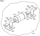
- Fig. 7 is a diagram showing a mounted structure of fuse element 230 (electric component). As shown in Fig. 7 , fuse element 230 is provided to be separated from housing 201A composed of a metal and constituting a portion of case member 200A. It should be noted that the mounted structure of fuse element 230 will be illustratively described below; however, the electric component according to the present technology is not limited to fuse element 230, and the same mounted structure can be also applied to other electric components such as main relay 240 (relay element), for example.
- main relay 240 relay element
- Fuse element 230 has a terminal 231A (first terminal) and a terminal 231B (second terminal).
- a bus bar 290A (first bus bar) is connected to terminal 231A, and a bus bar 290B (second bus bar) is connected to terminal 231B.
- Bus bars 290A, 290B respectively include: first portions 291A, 291B each connected to fuse element 230; second portions 292A, 292B provided at positions close to housing 201A with respect to first portions 291A, 291B; and third portions 293A, 293B provided at positions away from housing 201A with respect to second portions 292A, 292B.
- the heights (separation heights) of first portions 291A, 291B from housing 201A may be substantially the same as or different from the heights (separation heights) of third portions 293A, 293B from housing 201A.
- first portions 291A, 291B, second portions 292A, 292B, and third portions 293A, 293B of bus bars 290A, 290B can be formed by performing a bending process onto a plate-shaped member composed of a metal. It should be noted that a bus bar constituted only of first portions 291A, 291B and second portions 292A, 292B may be formed without forming third portions 293A, 293B.
- Heat transfer member 200D (heat transfer portion) having an insulating property and a thermal conductivity higher than that of air is provided.
- Heat transfer member 200D is preferably composed of a material having thermal conductivity and dielectric strength each having a value equal to or more than a certain value.
- heat transfer member 200D preferably has a thermal conductivity of about 1.0 W/m ⁇ K or more.
- heat transfer member 200D is constituted of a sheet-shaped member having elasticity and including an acrylic-based resin (thermally conductive acrylic-based heat-radiation material). More specifically, heat transfer member 200D may be formed using 6500H provided by 3M Company.
- heat transfer member 200D is not limited to the one described above, and heat transfer member 200D may be composed of a gel-like material, for example.
- electric pack 200 heat generated in fuse element 230 is transferred from fuse element 230 to housing 201A composed of a metal via bus bars 290A, 290B and heat transfer members 200D, thereby efficiently radiating the heat.
- the electric component such as fuse element 230 can be efficiently cooled.
- the above-described mounted structure can be obtained only by processing bus bars 290A, 290B and installing heat transfer member 200D, the structure of electric pack 200 is suppressed from being complicated.
- Fig. 8 is an enlarged cross sectional view showing a modification of the structure around heat transfer member 200D.
- cooling plate 200B having a coolant path 201B and housing 201A overlap with each other.
- a gap filler 200C (filling material) having a thermal conduction property is provided in a clearance formed between housing 201A and cooling plate 200B.
- Heat transfer member 200D is provided at a position overlapping with the clearance in which gap filler 200C is provided.
- Gap filler 200C may be in the form of a paste or may be in the form of a sheet obtained by curing the paste. Gap filler 200C preferably has a thermal conductivity comparable to or higher than that of heat transfer member 200D.
- the heat generated in fuse element 230 is transferred from fuse element 230 to housing 201A via bus bar 290A and heat transfer member 200D, and is further transferred to cooling plate 200B having coolant path 201B via gap filler 200C.
- efficiency of cooling of fuse element 230 can be further improved.
Landscapes
- Chemical & Material Sciences (AREA)
- Chemical Kinetics & Catalysis (AREA)
- Electrochemistry (AREA)
- General Chemical & Material Sciences (AREA)
- Engineering & Computer Science (AREA)
- Manufacturing & Machinery (AREA)
- Microelectronics & Electronic Packaging (AREA)
- Inorganic Chemistry (AREA)
- Mechanical Engineering (AREA)
- Physics & Mathematics (AREA)
- Thermal Sciences (AREA)
- Battery Mounting, Suspending (AREA)
- Secondary Cells (AREA)
- Connection Of Batteries Or Terminals (AREA)
- Aviation & Aerospace Engineering (AREA)
Applications Claiming Priority (1)
| Application Number | Priority Date | Filing Date | Title |
|---|---|---|---|
| JP2022205360A JP7724763B2 (ja) | 2022-12-22 | 2022-12-22 | 電気機器および電池パックシステム |
Publications (1)
| Publication Number | Publication Date |
|---|---|
| EP4391745A1 true EP4391745A1 (en) | 2024-06-26 |
Family
ID=88689373
Family Applications (1)
| Application Number | Title | Priority Date | Filing Date |
|---|---|---|---|
| EP23207522.6A Pending EP4391745A1 (en) | 2022-12-22 | 2023-11-02 | Electric device and battery pack system |
Country Status (5)
| Country | Link |
|---|---|
| US (1) | US20240213571A1 (https=) |
| EP (1) | EP4391745A1 (https=) |
| JP (1) | JP7724763B2 (https=) |
| KR (1) | KR20240100265A (https=) |
| CN (1) | CN118248982A (https=) |
Citations (5)
| Publication number | Priority date | Publication date | Assignee | Title |
|---|---|---|---|---|
| JPH058947U (ja) | 1991-07-15 | 1993-02-05 | オムロン株式会社 | 固体継電器 |
| JP2000125448A (ja) | 1998-10-14 | 2000-04-28 | Yazaki Corp | 電気接続箱 |
| US20190318892A1 (en) * | 2016-12-05 | 2019-10-17 | Toyota Jidosha Kabushiki Kaisha | Relay unit |
| WO2021230077A1 (ja) * | 2020-05-13 | 2021-11-18 | 株式会社オートネットワーク技術研究所 | 回路ユニット |
| EP3993141A1 (en) * | 2019-08-12 | 2022-05-04 | LG Energy Solution, Ltd. | Busbar having excellent insulation and heat dissipation performance and battery module comprising same |
Family Cites Families (5)
| Publication number | Priority date | Publication date | Assignee | Title |
|---|---|---|---|---|
| JP5825264B2 (ja) | 2011-01-21 | 2015-12-02 | 株式会社Gsユアサ | 電池システム |
| JP6081128B2 (ja) | 2012-10-10 | 2017-02-15 | 三洋電機株式会社 | 電源装置及びこれを備える車両並びに蓄電装置 |
| JP5714077B2 (ja) | 2013-10-25 | 2015-05-07 | 三菱電機株式会社 | 接続導体の冷却装置及びそれを用いた電力変換装置 |
| JP6295901B2 (ja) | 2014-09-24 | 2018-03-20 | トヨタ自動車株式会社 | 蓄電装置 |
| JP6826331B1 (ja) | 2019-07-15 | 2021-02-03 | 株式会社オートネットワーク技術研究所 | 回路構成体 |
-
2022
- 2022-12-22 JP JP2022205360A patent/JP7724763B2/ja active Active
-
2023
- 2023-11-02 EP EP23207522.6A patent/EP4391745A1/en active Pending
- 2023-12-05 CN CN202311660477.8A patent/CN118248982A/zh active Pending
- 2023-12-19 KR KR1020230185461A patent/KR20240100265A/ko active Pending
- 2023-12-20 US US18/391,163 patent/US20240213571A1/en active Pending
Patent Citations (5)
| Publication number | Priority date | Publication date | Assignee | Title |
|---|---|---|---|---|
| JPH058947U (ja) | 1991-07-15 | 1993-02-05 | オムロン株式会社 | 固体継電器 |
| JP2000125448A (ja) | 1998-10-14 | 2000-04-28 | Yazaki Corp | 電気接続箱 |
| US20190318892A1 (en) * | 2016-12-05 | 2019-10-17 | Toyota Jidosha Kabushiki Kaisha | Relay unit |
| EP3993141A1 (en) * | 2019-08-12 | 2022-05-04 | LG Energy Solution, Ltd. | Busbar having excellent insulation and heat dissipation performance and battery module comprising same |
| WO2021230077A1 (ja) * | 2020-05-13 | 2021-11-18 | 株式会社オートネットワーク技術研究所 | 回路ユニット |
Also Published As
| Publication number | Publication date |
|---|---|
| JP7724763B2 (ja) | 2025-08-18 |
| JP2024089864A (ja) | 2024-07-04 |
| US20240213571A1 (en) | 2024-06-27 |
| CN118248982A (zh) | 2024-06-25 |
| KR20240100265A (ko) | 2024-07-01 |
Similar Documents
| Publication | Publication Date | Title |
|---|---|---|
| EP4148876B1 (en) | Battery, electrical device, and method and device for preparing battery | |
| CN114128020B (zh) | 电池模块和包括该电池模块的电池组 | |
| CN113300037B (zh) | 电池、用电设备及电池的制造方法 | |
| CN214625290U (zh) | 电池组及包括该电池组的装置 | |
| CN116097517B (zh) | 电池、用电设备和电池的制备方法 | |
| US12525667B2 (en) | Battery module | |
| KR20230027234A (ko) | 전지 셀, 전지, 전기 장치, 및 전지 셀의 제조 장치 및 방법 | |
| EP4266464A1 (en) | Battery, electric device, and method and device for preparing battery | |
| EP4224595A1 (en) | Battery pack | |
| CN219040669U (zh) | 电池以及用电装置 | |
| US20230253684A1 (en) | Battery pack | |
| KR20130113145A (ko) | 안전성이 향상된 단위모듈 어셈블리 및 이를 포함하는 전지모듈 | |
| CN116134669B (zh) | 电池、用电设备、制备电池的方法和设备 | |
| EP4391745A1 (en) | Electric device and battery pack system | |
| US20250118843A1 (en) | Battery pack | |
| JP2023535774A (ja) | 電池モジュールおよびそれを含む電池パック | |
| EP4333157A1 (en) | Battery module | |
| US20240014503A1 (en) | Battery module | |
| CN120109338A (zh) | 汇流条支架组件、包括其的电池模组及其制造方法 | |
| EP4258437B1 (en) | Battery and electric device | |
| KR20190112579A (ko) | 전압 편차 감소를 위한 센싱 버스바 | |
| US20250118854A1 (en) | Battery pack | |
| US20240291093A1 (en) | Battery pack and method of manufacturing same | |
| US20240291096A1 (en) | Battery pack | |
| EP4661203A1 (en) | Battery pack and vehicle including same |
Legal Events
| Date | Code | Title | Description |
|---|---|---|---|
| PUAI | Public reference made under article 153(3) epc to a published international application that has entered the european phase |
Free format text: ORIGINAL CODE: 0009012 |
|
| STAA | Information on the status of an ep patent application or granted ep patent |
Free format text: STATUS: REQUEST FOR EXAMINATION WAS MADE |
|
| 17P | Request for examination filed |
Effective date: 20231102 |
|
| AK | Designated contracting states |
Kind code of ref document: A1 Designated state(s): AL AT BE BG CH CY CZ DE DK EE ES FI FR GB GR HR HU IE IS IT LI LT LU LV MC ME MK MT NL NO PL PT RO RS SE SI SK SM TR |