EP4391237A1 - Kabelverbinder - Google Patents
Kabelverbinder Download PDFInfo
- Publication number
- EP4391237A1 EP4391237A1 EP23193836.6A EP23193836A EP4391237A1 EP 4391237 A1 EP4391237 A1 EP 4391237A1 EP 23193836 A EP23193836 A EP 23193836A EP 4391237 A1 EP4391237 A1 EP 4391237A1
- Authority
- EP
- European Patent Office
- Prior art keywords
- shielding element
- metal shielding
- front ring
- main body
- cable
- Prior art date
- Legal status (The legal status is an assumption and is not a legal conclusion. Google has not performed a legal analysis and makes no representation as to the accuracy of the status listed.)
- Pending
Links
Images


Classifications
-
- H—ELECTRICITY
- H01—ELECTRIC ELEMENTS
- H01R—ELECTRICALLY-CONDUCTIVE CONNECTIONS; STRUCTURAL ASSOCIATIONS OF A PLURALITY OF MUTUALLY-INSULATED ELECTRICAL CONNECTING ELEMENTS; COUPLING DEVICES; CURRENT COLLECTORS
- H01R9/00—Structural associations of a plurality of mutually-insulated electrical connecting elements, e.g. terminal strips or terminal blocks; Terminals or binding posts mounted upon a base or in a case; Bases therefor
- H01R9/03—Connectors arranged to contact a plurality of the conductors of a multiconductor cable, e.g. tapping connections
- H01R9/05—Connectors arranged to contact a plurality of the conductors of a multiconductor cable, e.g. tapping connections for coaxial cables
- H01R9/0524—Connection to outer conductor by action of a clamping member, e.g. screw fastening means
-
- H—ELECTRICITY
- H01—ELECTRIC ELEMENTS
- H01R—ELECTRICALLY-CONDUCTIVE CONNECTIONS; STRUCTURAL ASSOCIATIONS OF A PLURALITY OF MUTUALLY-INSULATED ELECTRICAL CONNECTING ELEMENTS; COUPLING DEVICES; CURRENT COLLECTORS
- H01R13/00—Details of coupling devices of the kinds covered by groups H01R12/70 or H01R24/00 - H01R33/00
- H01R13/648—Protective earth or shield arrangements on coupling devices, e.g. anti-static shielding
- H01R13/658—High frequency shielding arrangements, e.g. against EMI [Electro-Magnetic Interference] or EMP [Electro-Magnetic Pulse]
- H01R13/6581—Shield structure
- H01R13/6582—Shield structure with resilient means for engaging mating connector
-
- H—ELECTRICITY
- H01—ELECTRIC ELEMENTS
- H01R—ELECTRICALLY-CONDUCTIVE CONNECTIONS; STRUCTURAL ASSOCIATIONS OF A PLURALITY OF MUTUALLY-INSULATED ELECTRICAL CONNECTING ELEMENTS; COUPLING DEVICES; CURRENT COLLECTORS
- H01R13/00—Details of coupling devices of the kinds covered by groups H01R12/70 or H01R24/00 - H01R33/00
- H01R13/648—Protective earth or shield arrangements on coupling devices, e.g. anti-static shielding
- H01R13/658—High frequency shielding arrangements, e.g. against EMI [Electro-Magnetic Interference] or EMP [Electro-Magnetic Pulse]
- H01R13/6591—Specific features or arrangements of connection of shield to conductive members
- H01R13/6592—Specific features or arrangements of connection of shield to conductive members the conductive member being a shielded cable
-
- H—ELECTRICITY
- H01—ELECTRIC ELEMENTS
- H01R—ELECTRICALLY-CONDUCTIVE CONNECTIONS; STRUCTURAL ASSOCIATIONS OF A PLURALITY OF MUTUALLY-INSULATED ELECTRICAL CONNECTING ELEMENTS; COUPLING DEVICES; CURRENT COLLECTORS
- H01R2103/00—Two poles
-
- H—ELECTRICITY
- H01—ELECTRIC ELEMENTS
- H01R—ELECTRICALLY-CONDUCTIVE CONNECTIONS; STRUCTURAL ASSOCIATIONS OF A PLURALITY OF MUTUALLY-INSULATED ELECTRICAL CONNECTING ELEMENTS; COUPLING DEVICES; CURRENT COLLECTORS
- H01R24/00—Two-part coupling devices, or either of their cooperating parts, characterised by their overall structure
- H01R24/38—Two-part coupling devices, or either of their cooperating parts, characterised by their overall structure having concentrically or coaxially arranged contacts
- H01R24/40—Two-part coupling devices, or either of their cooperating parts, characterised by their overall structure having concentrically or coaxially arranged contacts specially adapted for high frequency
Definitions
- the present invention is related to an electrical connector, more particularly to a cable connector.
- a conventional cable connector includes an outer housing 6, a supporting sleeve 7, and a cable 8.
- the outer housing 6 includes a first housing 60 and a second housing 61 mounted around the first housing 60.
- the first housing 60 includes a sleeve portion 601 and an indentation ring portion 602 adjacent to the second housing 61 and concavely formed.
- the cable 8 includes an outer insulation jacket, an outer conductor 80, an insulation layer 81, and an inner conductor 82 arranged in coaxial from outside to inside.
- the inner conductor 82, the insulation layer 81, and the outer conductor 80 are exposed from a front section of the cable 8 in sequence.
- the supporting sleeve 7 is mounted around the exposed outer conductor 80.
- the outer conductor 80 is folded outward and backward along an outside of the supporting sleeve 7 since the outer conductor 80 is longer than the supporting sleeve 7.
- the supporting sleeve 7 and the folded outer conductor 80 are mounted in the sleeve portion 601 of the first housing 60 together.
- the exposed insulation layer 81 and the inner conductor 82 mounted therein are clamped by the indentation ring portion 602.
- the first housing 60 and the second housing 61 are combined to form the outer housing 6 of the conventional cable connector. Therefore, the two-piece first and second housings 60 and 61 need to be manufactured separately and then assembled as the outer housing 6 by an additional step thereafter to complete the conventional cable connector. Thus, after the conventional cable connector has been plugged and unplugged many times, the first and second housings 60 and 61 may separate from each other to become invalid. Furthermore, the outer conductor 80 needs to be folded outward and backward along the outside of the supporting sleeve 7 to be firmly fastened in the sleeve portion 601 of the first housing 60.
- the indentation ring portion 602 is required to be formed on the first housing 60 to further clamp the exposed insulation layer 81 and the inner conductor 82 mounted therein. Therefore, the assembling steps and the manufacturing process of the conventional cable connector are complicated and the conventional cable connector needs to be improved.
- An objective of the present invention is to provide a cable connector.
- the cable connector includes:
- the cable connector of the present invention mainly applies the metal housing integrally formed.
- the first inner metal shielding element is mainly accommodated in the main body of the sleeve portion of the metal housing.
- the outer surface of the first inner metal shielding element is abutted against the inner surface of the main body.
- the outer conductor of the cable is firmly fastened in the metal housing by being clamped by the first inner metal shielding element. Therefore, the cable is fastened in the metal housing in which the outer conductor does not need to be folded outward and backward along an outside of the first inner metal shielding element.
- the first inner metal shielding element may shield electromagnetic interference.
- the metal housing is integrally formed.
- the metal housing does not separate to become invalid. Moreover, a structure for fastening the cable does not need to be additionally formed on the metal housing. Accordingly, the assembling steps and the manufacturing process of the cable connector in accordance with the present invention is effectively simplified and the efficiency in high-frequency signal transmission of the cable connector is enhanced.
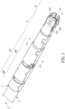
- a first embodiment of the cable connector of the present invention includes a metal housing 1, a receptacle 2, a cable 3, and a first inner metal shielding element 4 and may include an optional second inner metal shielding element 5.
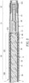
- the receptacle 2, a front section of the cable 3, and the first and second inner metal shielding elements 4 and 5 are accommodated in the metal housing 1 together.
- the metal housing 1 includes a sleeve portion 10, an intermediary portion 11, and a plug portion 12 formed integrally from rear to front.
- the metal housing 1 is cylindrical.
- a length of the sleeve portion 10 may be greater than a length of the intermediary portion 11 and a length of the plug portion 12 and the length of the intermediary portion 11 is greater than the length of the plug end 12 but are not limited thereto.
- the sleeve portion 10 of the metal housing 1 includes an end portion 100 and a main body 101.
- the main body 101 is formed between the intermediary portion 11 and the end portion 100.
- the main body 101 has a single outer diameter.
- the plug portion 12 includes three elongated notches 121 arranged in annular, three contacting elastic elements 122 arranged in annular, and three contacting bumps 123.
- Each elongated notch 121 is formed through the plug portion 12 from front to rear.
- Each contacting elastic element 122 is formed between two of the elongated notches 121.
- a front segment of each contacting elastic element 122 has a protruding part slightly protruding outward.
- Each contacting bump 123 is formed on the protruding part of each contacting elastic element 122.
- Each contacting bump 123 is outer than an outer side of a rear segment of the corresponding contacting elastic element 122.
- the corresponding two elongated notches 121 are arranged between 120 degrees.
- the corresponding two contacting bumps 123 of the contacting elastic elements 122 are also arranged between 120 degrees but are not limited thereto.
- a shrinking part 13 is further concavely formed on a boundary of the intermediary portion 11 and the main body 101 of the sleeve portion 10.
- the receptacle 2 is accommodated in the intermediary portion 11 and the plug portion 12 of the metal housing 1.
- the receptacle 2 includes a front end, a rear end, and an inner conductor terminal 20.
- the front end corresponds to the front segment of the contacting elastic element 122.
- the rear end corresponds to the shrinking part 13.
- the inner conductor terminal 20 is mounted through the receptacle 2 from front to rear.
- the inner conductor terminal 20 may be a hollow terminal but is not limited thereto.
- the receptacle 2 may further include an accommodating channel 21 formed through the first receptacle 2 from front to rear.
- the inner conductor terminal 20 is mounted through and accommodated in the accommodating channel 21.
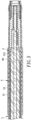
- the cable 3 includes an outer insulation jacket 30, an outer conductor 3 1 (such as a metal weaving net), a metal foil 34(such as an aluminum foil), an insulation layer 32, and an inner conductor 33.
- the inner conductor 33, the insulation layer 32, the metal foil 34, the outer conductor 31, and the outer insulation jacket 30 are exposed from front to rear of the cable 3 in sequence.
- the outer conductor 31 and the metal foil 34 protrude from the outer insulation jacket 30.
- a distal end of the outer conductor 31 is flush with a distal end of the metal foil 34.
- a first front ring segment 321 of the insulation layer 32 protrudes from the metal foil 34.
- the inner conductor 33 protrudes from the first front ring segment 321 of the insulation layer 32.
- the front section of the cable 3 is mounted through the sleeve portion 10 of the metal housing 1.
- the outer insulation jacket 30 is mounted in the end portion 100 of the sleeve portion 10 and an outer surface of the outer insulation jacket 30 is abutted against an inner surface of the end portion 100.
- the outer conductor 31 and the first front ring segment 321 of the insulation layer 32 are located in the main body 101 of the sleeve end 10. A distance is defined between the first front ring segment 321 and the inner surface of the main body 101.
- the first front ring segment 321 of the insulation layer 32 may be further close to the shrinking part 13. Therefore, a lateral distance is defined between the outer conductor 31 and the shrinking part 13 of the metal housing 1.
- the inner conductor 33 is located in the intermediary portion 11 and mounted through the receptacle 2 to be connected to the inner conductor terminal 20.
- the first inner metal shielding element 4 may be a cylindrical sleeve, is accommodated in the main body 101 of the sleeve portion 10, and is mounted around the outer conductor 31 of the cable 3.
- the first inner metal shielding element 4 is located between the outer conductor 31 and the main body 101 of the sleeve end 10 to clamp the outer conductor 31 with the insulation layer 32.
- An outer surface of the first inner metal shielding element 4 is abutted against the inner surface of the main body 101 and an inner surface of the first inner metal shielding element 4 is abutted against and firmly contacts with an outer surface of the outer conductor 31.
- the outer conductor 31 of the cable 3 is firmly fastened by the first inner metal shielding element 4 in the main body 101 of the sleeve portion 10.
- the cable 3 is firmly fastened in the metal housing 1.
- a thickness of the first inner metal shielding element 4 matches a thickness of the outer insulation jacket 30 of the cable 3.
- the first inner metal shielding element 4 has a front ring portion 40 corresponding to the lateral distance defined between the outer conductor 31 and the shrinking part 13.
- the front ring portion 40 is formed along the inner surface of the main body 101 and is close to the shrinking part 13.
- the front ring portion 40 is located between the first front ring segment 321 and the main body 101 and is formed around the first front ring segment 321. A gap is defined between the front ring portion 40 and the first front ring segment 321.
- the metal housing 1, the first inner metal shielding element 4, and the outer conductor 31 of the cable 3 are electrically connected.
- the outer conductor 31 is connected to the ground to conduct the external electromagnetic interference and the noise away from the cable connector.
- the second inner metal shielding element 5 is mounted in the gap defined between the front ring portion 40 and the first front ring segment 321 of the insulation layer 32.
- the first and second inner metal shielding elements 4 and 5 are integrally formed.
- the second inner metal shielding element 5 may be formed by integrally bending the front ring portion 40 inward along the inner surface of the first inner metal shielding element 4 at the shrinking part 13.
- a plurality of bumps 50 are formed on an outer surface of the second inner metal shielding element 5. The bumps 50 are abutted against the inner surface of the first inner metal shielding element 4.
- the second inner metal shielding element 5 may include four bumps 50 but is not limited thereto.
- a sum of a thickness of the front ring portion 40 of the first inner metal shielding element 4 and a thickness of the second inner metal shielding element 5 matches a distance defined between an outer surface of the first front ring segment 321 of the insulation layer 32 and an outer surface of the outer insulation jacket 30 of the cable 3.
- the first front ring segment 321 of the insulation layer 32 may be firmly fastened in the main body 101 of the sleeve portion 10 by being clamped between the front ring portion 40 of the first inner metal shielding element 4 and the second inner metal shielding element 5.
- the cable 3 may be firmly fastened in the metal housing 1.
- the second inner metal shielding element 5 is electrically connected to the first inner metal shielding element 4, the outer conductor 31 of the cable 3, and the metal housing 1. Therefore, the second inner metal shielding element 5 may shield and conduct away the electromagnetic interference at the first front ring segment 321 of the insulation layer 32 to reinforce the shielding ability instead of the absent outer conductor 31.
- a second embodiment of the cable connector is shown and similar to the cable connector shown in Fig. 3 .
- a first inner metal shielding elements 4 and a second inner metal shielding elements 5 are two individual sleeves.
- the second inner metal shielding element 5 is first mounted around the first front ring segment 321 of the insulation layer 32.
- the first inner metal shielding element 4 is then mounted around the outer conductor 31 and the second inner metal shielding element 5.
- the front ring portion 40 of the first inner metal shielding element 4 and the second inner metal shielding element 5 may be integrally formed.
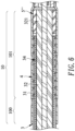
- a third embodiment of the cable connector is shown and similar to the cable connector shown in Fig. 3 .
- a distal end of a first inner metal shielding element 4 is flush with a distal end of the outer conductor 31 and the distal end of the metal foil 34.
- a gap is defined between the main body 101 of the sleeve portion 10 and the first front ring segment 321 of the insulation layer 32. Since the distal end of the first inner metal shielding element 4 is flush with the distal end of the outer conductor 31 and the distal end of the metal foil 34, the gap shown in Fig. 6 is greater than the gap shown in Fig. 3 .
- a second inner metal shielding element 5" is mounted in the gap defined between the main body 101 of the sleeve portion 10 and the first front ring segment 321 of the insulation layer 32.
- a thickness of the second inner metal shielding element 5" shown in Fig. 6 is greater than the second inner metal shielding element 5 shown in Fig. 3 .
- the thickness of the second inner metal shielding element 5" matches the distance defined between the outer surface of the first front ring segment 321 of the insulation layer 32 and the outer surface of the outer insulation jacket 30 of the cable 3.
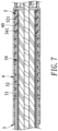
- a fourth embodiment and a fifth embodiment of the cable connector are shown and similar to the cable connector as shown in Figs. 3 and 5 .
- a second front ring segment 341 of the metal foil 34 of the cable 3 protrudes from the outer conductor 31.
- the second front ring segment 341 of the metal foil 34 extends along the first front ring segment 321 of the insulation layer 32.
- a distal end of the second front ring segment 341 is flush with a distal end of the first front ring segment 321.
- a gap is defined between the front ring portion 40 of the first inner metal shielding element 4 and the second ring segment 341 of the metal foil 34.
- a second inner metal shielding element 5 is mounted in the gap defined between the front ring portion 40 of the first inner metal shielding element 4 and the second ring segment 341 of the metal foil 34.
- the second inner metal shielding element 5 may include four bumps 50 shown in Fig. 4 but is not limited thereto.
- a sum of a thickness of the front ring portion 40 of the first inner metal shielding element 4 and a thickness of the second inner metal shielding element 5 matches a distance defined between an outer surface of the second front ring segment 341 of the metal foil 34 and an outer surface of the outer insulation jacket 30 of the cable 3.
- a sixth embodiment of the cable connector is shown and similar to the cable connector shown in Fig. 6 .
- the distal end of the first inner metal shielding element 4 is flush with the distal end of the outer conductor 31 of the cable 3.
- a gap is defined between the main body 101 of the sleeve portion 10 and the second front ring segment 341 of the metal foil 34.
- a size of the gap defined between the main body 101 and the front ring segment 341 is between a size of the gap defined between the front ring portion 40 and the first front ring segment 321 shown in Fig. 3 and a size of the gap defined between the main body 101 and the first front ring segment 321 shown in Fig. 6 .
- a second inner metal shielding element 5a is mounted in the gap defined between the main body 101 of the sleeve portion 10 and the second front ring segment 341 of the metal foil 34. Therefore, a thickness of the second inner metal shielding element 5a is between a thickness of the second inner metal shielding element 5 shown in Figs. 3 and a thickness of the second inner metal shielding element 5" shown in Fig. 6 . In one embodiment, the thickness of the second inner metal shielding element 5a matches the distance defined between the outer surface of the second front ring segment 341 of the metal foil 34 and the outer surface of the outer insulation jacket 30 of the cable 3.
- the cable connector of the present invention applies the metal housing integrally formed.
- the first inner metal shielding element is accommodated in the main body of the sleeve portion of the metal housing.
- the outer surface of the first inner metal shielding element is abutted against the inner surface of the main body.
- the outer conductor of the cable is firmly fastened in the metal housing by being clamped by the first inner metal shielding element. Therefore, the cable is fastened in the metal housing in which the outer conductor does not need to be folded outward and backward along an outside of the first inner metal shielding element.
- the second inner metal shielding element may be mounted around the different portions of the insulation layer exposed from the front section of the cable.
- the metal housing and/or the first inner metal shielding element may firmly clamp the different portions of the insulation layer with the second inner metal shielding element.
- An indented structure for fastening the front ring segment is not required to be formed on the metal housing. Accordingly, even if the cable connector has been plugged and unplugged many times, the metal housing does not separate to become invalid.
- the insulation layer exposed from the front section of the cable may be firmly clamped by the metal housing, the first inner metal shielding element, and/or the second inner metal shielding element.
- a structure for fastening the cable does not need to be additionally formed on the metal housing.
- the outer conductor and the first and second inner metal shielding elements may shield the electromagnetic interference and conduct the electromagnetic interference to the ground. Accordingly, the assembling steps and the manufacturing process of the cable connector in accordance with the present invention is effectively simplified and the efficiency in high-frequency signal transmission of the cable connector is enhanced.
Landscapes
- Details Of Connecting Devices For Male And Female Coupling (AREA)
- Coupling Device And Connection With Printed Circuit (AREA)
Applications Claiming Priority (1)
| Application Number | Priority Date | Filing Date | Title |
|---|---|---|---|
| TW111149817A TWI844211B (zh) | 2022-12-23 | 2022-12-23 | 纜線連接器 |
Publications (1)
| Publication Number | Publication Date |
|---|---|
| EP4391237A1 true EP4391237A1 (de) | 2024-06-26 |
Family
ID=87863066
Family Applications (1)
| Application Number | Title | Priority Date | Filing Date |
|---|---|---|---|
| EP23193836.6A Pending EP4391237A1 (de) | 2022-12-23 | 2023-08-29 | Kabelverbinder |
Country Status (2)
| Country | Link |
|---|---|
| EP (1) | EP4391237A1 (de) |
| TW (1) | TWI844211B (de) |
Cited By (1)
| Publication number | Priority date | Publication date | Assignee | Title |
|---|---|---|---|---|
| JP2025023280A (ja) * | 2022-02-07 | 2025-02-14 | 株式会社オートネットワーク技術研究所 | コネクタ |
Citations (2)
| Publication number | Priority date | Publication date | Assignee | Title |
|---|---|---|---|---|
| US20170271784A1 (en) * | 2016-03-17 | 2017-09-21 | Te Connectivity Germany Gmbh | Electrical Connection Device, A Method of Manufacturing an Electrical Cable and A Manufactured Electrical Coaxial Cable |
| US20220029364A1 (en) * | 2020-07-24 | 2022-01-27 | Te Connectivity Germany Gmbh | Electrical Ferrule, Electrical Connecting Device and Electrical Connector |
Family Cites Families (3)
| Publication number | Priority date | Publication date | Assignee | Title |
|---|---|---|---|---|
| JP3738388B2 (ja) * | 2002-04-24 | 2006-01-25 | 株式会社オートネットワーク技術研究所 | 同軸コネクタ |
| TWM384434U (en) * | 2010-02-10 | 2010-07-11 | Poni Tek Co Ltd | RF connector and its positioning sleeve |
| JP6734767B2 (ja) * | 2016-11-30 | 2020-08-05 | 日本航空電子工業株式会社 | コネクタ |
-
2022
- 2022-12-23 TW TW111149817A patent/TWI844211B/zh active
-
2023
- 2023-08-29 EP EP23193836.6A patent/EP4391237A1/de active Pending
Patent Citations (2)
| Publication number | Priority date | Publication date | Assignee | Title |
|---|---|---|---|---|
| US20170271784A1 (en) * | 2016-03-17 | 2017-09-21 | Te Connectivity Germany Gmbh | Electrical Connection Device, A Method of Manufacturing an Electrical Cable and A Manufactured Electrical Coaxial Cable |
| US20220029364A1 (en) * | 2020-07-24 | 2022-01-27 | Te Connectivity Germany Gmbh | Electrical Ferrule, Electrical Connecting Device and Electrical Connector |
Cited By (1)
| Publication number | Priority date | Publication date | Assignee | Title |
|---|---|---|---|---|
| JP2025023280A (ja) * | 2022-02-07 | 2025-02-14 | 株式会社オートネットワーク技術研究所 | コネクタ |
Also Published As
| Publication number | Publication date |
|---|---|
| TW202427871A (zh) | 2024-07-01 |
| TWI844211B (zh) | 2024-06-01 |
Similar Documents
| Publication | Publication Date | Title |
|---|---|---|
| US6468110B2 (en) | Shielded-cable connector improved in transmission characteristics | |
| US20020037669A1 (en) | Electronic signal plug connector | |
| US6753475B2 (en) | Shielding terminal for coaxial cable | |
| JPS6329952B2 (de) | ||
| US20180375232A1 (en) | Cable connector assembly | |
| CN112821099B (zh) | 连接装置及电线连接结构 | |
| US10424880B2 (en) | Shield connector and method for connecting same | |
| EP4391237A1 (de) | Kabelverbinder | |
| CN110829127A (zh) | 同轴连接器 | |
| CN113196580B (zh) | 端子模块及连接器 | |
| TWI669867B (zh) | Coaxial connector | |
| JP7357913B2 (ja) | 同軸コネクタ | |
| JP2006024499A (ja) | 同軸ケーブル用コネクタ | |
| JP3281597B2 (ja) | シールド電線の端末処理構造 | |
| JP7128511B2 (ja) | シールドコネクタ | |
| JP2026503775A (ja) | 角度付きコネクタ | |
| JP2008123913A (ja) | 内導体端子及び同軸コネクタ | |
| JP2021099931A (ja) | シールドコネクタ | |
| CN114175414B (zh) | 连接器及连接器装置 | |
| US6619988B2 (en) | Connector assembly | |
| US12620749B2 (en) | Cable connector and metal housing thereof | |
| US20240145980A1 (en) | Cable connector and metal housing thereof | |
| CN118263702A (zh) | 电缆连接器 | |
| JP3693973B2 (ja) | L字プラグとその組み立て方法 | |
| JP2009238465A (ja) | シールド電線付きコネクタ |
Legal Events
| Date | Code | Title | Description |
|---|---|---|---|
| PUAI | Public reference made under article 153(3) epc to a published international application that has entered the european phase |
Free format text: ORIGINAL CODE: 0009012 |
|
| STAA | Information on the status of an ep patent application or granted ep patent |
Free format text: STATUS: THE APPLICATION HAS BEEN PUBLISHED |
|
| AK | Designated contracting states |
Kind code of ref document: A1 Designated state(s): AL AT BE BG CH CY CZ DE DK EE ES FI FR GB GR HR HU IE IS IT LI LT LU LV MC ME MK MT NL NO PL PT RO RS SE SI SK SM TR |
|
| STAA | Information on the status of an ep patent application or granted ep patent |
Free format text: STATUS: REQUEST FOR EXAMINATION WAS MADE |
|
| 17P | Request for examination filed |
Effective date: 20241011 |
|
| RBV | Designated contracting states (corrected) |
Designated state(s): AL AT BE BG CH CY CZ DE DK EE ES FI FR GB GR HR HU IE IS IT LI LT LU LV MC ME MK MT NL NO PL PT RO RS SE SI SK SM TR |
|
| GRAP | Despatch of communication of intention to grant a patent |
Free format text: ORIGINAL CODE: EPIDOSNIGR1 |
|
| STAA | Information on the status of an ep patent application or granted ep patent |
Free format text: STATUS: GRANT OF PATENT IS INTENDED |
|
| RIC1 | Information provided on ipc code assigned before grant |
Ipc: H01R 9/05 20060101AFI20260121BHEP Ipc: H01R 13/6582 20110101ALI20260121BHEP Ipc: H01R 13/6592 20110101ALI20260121BHEP Ipc: H01R 24/40 20110101ALN20260121BHEP |
|
| RIC1 | Information provided on ipc code assigned before grant |
Ipc: H01R 9/05 20060101AFI20260129BHEP Ipc: H01R 13/6582 20110101ALI20260129BHEP Ipc: H01R 13/6592 20110101ALI20260129BHEP Ipc: H01R 24/40 20110101ALN20260129BHEP |
|
| INTG | Intention to grant announced |
Effective date: 20260223 |
|
| RIC1 | Information provided on ipc code assigned before grant |
Ipc: H01R 9/05 20060101AFI20260216BHEP Ipc: H01R 13/6582 20110101ALI20260216BHEP Ipc: H01R 13/6592 20110101ALI20260216BHEP Ipc: H01R 24/40 20110101ALN20260216BHEP |
|
| GRAS | Grant fee paid |
Free format text: ORIGINAL CODE: EPIDOSNIGR3 |
|
| GRAA | (expected) grant |
Free format text: ORIGINAL CODE: 0009210 |
|
| STAA | Information on the status of an ep patent application or granted ep patent |
Free format text: STATUS: THE PATENT HAS BEEN GRANTED |