EP4390600A1 - Transport system, automated guided vehicle, and method for controlling automated guided vehicle - Google Patents
Transport system, automated guided vehicle, and method for controlling automated guided vehicle Download PDFInfo
- Publication number
- EP4390600A1 EP4390600A1 EP22895157.0A EP22895157A EP4390600A1 EP 4390600 A1 EP4390600 A1 EP 4390600A1 EP 22895157 A EP22895157 A EP 22895157A EP 4390600 A1 EP4390600 A1 EP 4390600A1
- Authority
- EP
- European Patent Office
- Prior art keywords
- automated guided
- guided vehicle
- transported object
- lifting platform
- station
- Prior art date
- Legal status (The legal status is an assumption and is not a legal conclusion. Google has not performed a legal analysis and makes no representation as to the accuracy of the status listed.)
- Pending
Links
Images







Classifications
-
- B—PERFORMING OPERATIONS; TRANSPORTING
- B66—HOISTING; LIFTING; HAULING
- B66F—HOISTING, LIFTING, HAULING OR PUSHING, NOT OTHERWISE PROVIDED FOR, e.g. DEVICES WHICH APPLY A LIFTING OR PUSHING FORCE DIRECTLY TO THE SURFACE OF A LOAD
- B66F9/00—Devices for lifting or lowering bulky or heavy goods for loading or unloading purposes
- B66F9/06—Devices for lifting or lowering bulky or heavy goods for loading or unloading purposes movable, with their loads, on wheels or the like, e.g. fork-lift trucks
- B66F9/063—Automatically guided
-
- G—PHYSICS
- G05—CONTROLLING; REGULATING
- G05D—SYSTEMS FOR CONTROLLING OR REGULATING NON-ELECTRIC VARIABLES
- G05D1/00—Control of position, course, altitude or attitude of land, water, air or space vehicles, e.g. using automatic pilots
- G05D1/20—Control system inputs
- G05D1/22—Command input arrangements
- G05D1/221—Remote-control arrangements
- G05D1/225—Remote-control arrangements operated by off-board computers
-
- G—PHYSICS
- G05—CONTROLLING; REGULATING
- G05D—SYSTEMS FOR CONTROLLING OR REGULATING NON-ELECTRIC VARIABLES
- G05D1/00—Control of position, course, altitude or attitude of land, water, air or space vehicles, e.g. using automatic pilots
- G05D1/60—Intended control result
- G05D1/646—Following a predefined trajectory, e.g. a line marked on the floor or a flight path
-
- G—PHYSICS
- G05—CONTROLLING; REGULATING
- G05D—SYSTEMS FOR CONTROLLING OR REGULATING NON-ELECTRIC VARIABLES
- G05D1/00—Control of position, course, altitude or attitude of land, water, air or space vehicles, e.g. using automatic pilots
- G05D1/60—Intended control result
- G05D1/656—Interaction with payloads or external entities
- G05D1/667—Delivering or retrieving payloads
-
- G—PHYSICS
- G05—CONTROLLING; REGULATING
- G05D—SYSTEMS FOR CONTROLLING OR REGULATING NON-ELECTRIC VARIABLES
- G05D1/00—Control of position, course, altitude or attitude of land, water, air or space vehicles, e.g. using automatic pilots
- G05D1/60—Intended control result
- G05D1/69—Coordinated control of the position or course of two or more vehicles
- G05D1/698—Control allocation
- G05D1/6987—Control allocation by centralised control off-board any of the vehicles
-
- G—PHYSICS
- G05—CONTROLLING; REGULATING
- G05D—SYSTEMS FOR CONTROLLING OR REGULATING NON-ELECTRIC VARIABLES
- G05D2105/00—Specific applications of the controlled vehicles
- G05D2105/20—Specific applications of the controlled vehicles for transportation
- G05D2105/28—Specific applications of the controlled vehicles for transportation of freight
-
- G—PHYSICS
- G05—CONTROLLING; REGULATING
- G05D—SYSTEMS FOR CONTROLLING OR REGULATING NON-ELECTRIC VARIABLES
- G05D2107/00—Specific environments of the controlled vehicles
- G05D2107/70—Industrial sites, e.g. warehouses or factories
-
- G—PHYSICS
- G05—CONTROLLING; REGULATING
- G05D—SYSTEMS FOR CONTROLLING OR REGULATING NON-ELECTRIC VARIABLES
- G05D2109/00—Types of controlled vehicles
- G05D2109/10—Land vehicles
Definitions
- An aspect of the present invention relates to a transport system, an automated guided vehicle, and a method for controlling the automated guided vehicle.
- Patent Literature 1 discloses a system including an unmanned vehicle configured to get under a wagon truck (transported object) to lift up the wagon truck, the system configured to transport the wagon truck by the unmanned vehicle to a destination instructed from the outside.
- Patent Literature 1 Japanese Unexamined Patent Publication No. H9-185413
- a transported object having a long shape in plan view may be transported while being placed on the lifting platform of the automated guided vehicle in some cases.
- the transported object is placed on the lifting platform so that a longitudinal direction of the transported object coincides with a width direction of the passage, a problem may be caused such that a large part of the passage is blocked and traffic tends to be hindered.
- An object of an aspect of the present invention is to provide a transport system, an automated guided vehicle, and a method for controlling the automated guided vehicle with which the automated guided vehicle that is transporting the transported object can be prevented from hindering traffic.
- a transport system includes: a transported object having a long shape in plan view; a station at which the transported object is disposed; and an automated guided vehicle including a lifting platform on which the transported object is placed, the automated guided vehicle being configured to self-travel along a predetermined traveling route.
- the automated guided vehicle has a total length of a vehicle body shorter than a dimension in a longitudinal direction of the transported object in plan view, and a vehicle body width shorter than a dimension in a lateral direction of the transported object in plan view, and performs a first traveling direction change operation of changing a traveling direction of the automated guided vehicle so that the traveling direction of the automated guided vehicle is in parallel with the longitudinal direction of the transported object in a state of being under a lower part of the transported object.
- the longitudinal direction of the transported object transported by the automated guided vehicle can be caused to be in parallel with the traveling direction of the automated guided vehicle (hereinafter, also simply referred to as a "traveling direction") by the first traveling direction change operation.
- a traveling direction of the automated guided vehicle hereinafter, also simply referred to as a "traveling direction”
- the automated guided vehicle that is transporting the transported object can be prevented from hindering traffic.
- the first traveling direction change operation may be performed during a period from when the automated guided vehicle enters the station from the predetermined traveling route until the automated guided vehicle returns to the predetermined traveling route from the station.
- the first traveling direction change operation has been already performed and the longitudinal direction of the transported object is in parallel with the traveling direction, so that the automated guided vehicle can be securely prevented from hindering traffic.
- the predetermined traveling route may be a route that is planned every time the automated guided vehicle performs automatic traveling on a route from the present location to a destination, or may be a route that is planned by a user of the automated guided vehicle or the transport system to be continuously used thereafter.
- the automated guided vehicle may perform an entry operation of entering the lower part of the transported object from one side or the other side in the lateral direction. Due to this, the automated guided vehicle can smoothly enter the lower part of the transported object.
- the automated guided vehicle in the case of carrying out the transported object from the station, may perform the entry operation of entering the lower part of the transported object disposed at the station, perform the first traveling direction change operation, make connection with the transported object by raising the lifting platform and placing the transported object on the lifting platform, and come out from the station together with the transported object.
- the transported object transported by the automated guided vehicle while the longitudinal direction of the transported object transported by the automated guided vehicle is caused to be in parallel with the traveling direction, the transported object can be easily carried out from the station around which no obstacle is present.
- the automated guided vehicle in the case of carrying out the transported object from the station, may perform the entry operation of entering the lower part of the transported object disposed at the station, make connection with the transported object by raising the lifting platform and placing the transported object on the lifting platform, come out from the station together with the transported object, disconnect the transported object by lowering the lifting platform and taking down the transported object from the lifting platform, perform the first traveling direction change operation, and make connection with the transported object by raising the lifting platform and placing the transported object on the lifting platform.
- the transported object transported by the automated guided vehicle while the longitudinal direction of the transported object transported by the automated guided vehicle is caused to be in parallel with the traveling direction, the transported object can be easily carried out from the station around which an obstacle is present.
- a spin turn may be performed to pivot the automated guided vehicle at a present place in the first traveling direction change operation.
- the traveling direction of the automated guided vehicle can be caused to be in parallel with the longitudinal direction of the transported object by using the spin turn.
- the automated guided vehicle may perform a second traveling direction change operation of changing the traveling direction of the automated guided vehicle so that the traveling direction of the automated guided vehicle is in parallel with the lateral direction of the transported object in a state of being under the lower part of the transported object. Due to this, the automated guided vehicle can easily carry the transported object into stations of various aspects by using the second traveling direction change operation.
- the automated guided vehicle may perform a coming-out operation of coming out from one side or the other side in the lateral direction of the lower part of the transported object. Due to this, the automated guided vehicle can smoothly come out from the lower part of the transported object.
- the automated guided vehicle in the case of the automated guided vehicle connected to the transported object by placing the transported object on the lifting platform so that the traveling direction of the automated guided vehicle is in parallel with the longitudinal direction of the transported object, in the case that such an automated guided vehicle carries the transported object into the station, the automated guided vehicle may enter the station together with the transported object, disconnect the transported object by lowering the lifting platform and taking down the transported object from the lifting platform, perform the second traveling direction change operation, and perform the coming-out operation to come out from the station.
- the transported object can be easily carried into the station around which no obstacle is present.
- the automated guided vehicle in the case of the automated guided vehicle connected to the transported object by placing the transported object on the lifting platform so that the traveling direction of the automated guided vehicle is in parallel with the longitudinal direction of the transported object, in the case that such an automated guided vehicle carries the transported object into the station, the automated guided vehicle may disconnect the transported object by lowering the lifting platform and taking down the transported object from the lifting platform, perform the second traveling direction change operation, make connection with the transported object by raising the lifting platform and placing the transported object on the lifting platform, enter the station together with the transported object, disconnect the transported object by lowering the lifting platform and taking down the transported object from the lifting platform, and perform the coming-out operation to come out from the station.
- the transported object transported object transported by the automated guided vehicle while the longitudinal direction of the transported object transported by the automated guided vehicle is caused to be in parallel with the traveling direction, the transported object can be easily carried into the station around which an obstacle is present.
- a spin turn may be performed to pivot the automated guided vehicle at a present place in the second traveling direction change operation.
- the traveling direction of the automated guided vehicle can be caused to be in parallel with the lateral direction of the transported object by using the spin turn.
- the transported object may be a cart configured to carry articles.
- the effect described above can be exhibited in the system in which the cart is transported by the automated guided vehicle.
- the automated guided vehicle is an automated guided vehicle including a lifting platform on which a transported object having a long shape in plan view is placed, the automated guided vehicle being configured to self-travel along a predetermined traveling route.
- the automated guided vehicle has a total length of a vehicle body shorter than a dimension in a longitudinal direction of the transported object in plan view, and a vehicle body width shorter than a dimension in a lateral direction of the transported object in plan view, and performs a first traveling direction change operation of changing a traveling direction of the automated guided vehicle so that the traveling direction of the automated guided vehicle is in parallel with the longitudinal direction of the transported object in a state of being under a lower part of the transported object.
- the longitudinal direction of the transported object to be transported can be caused to be in parallel with the traveling direction by the first traveling direction change operation.
- the automated guided vehicle that is transporting the transported object can be prevented from hindering traffic.
- a method for controlling the automated guided vehicle is a method for controlling an operation of an automated guided vehicle including a lifting platform on which a transported object having a long shape in plan view is placed, the automated guided vehicle being configured to self-travel along a predetermined traveling route, in which the automated guided vehicle has a total length of a vehicle body shorter than a dimension in a longitudinal direction of the transported object in plan view, and a vehicle body width shorter than a dimension in a lateral direction of the transported object in plan view, and the method includes a first traveling direction change step of changing a traveling direction of the automated guided vehicle so that the traveling direction of the automated guided vehicle is in parallel with the longitudinal direction of the transported object in a state in which the automated guided vehicle is under a lower part of the transported object.
- the longitudinal direction of the transported object transported by the automated guided vehicle can be caused to be in parallel with the traveling direction at the first traveling direction change step.
- the automated guided vehicle that is transporting the transported object can be prevented from hindering traffic.
- FIG. 1 is a schematic configuration diagram illustrating a transport system 1 according to the embodiment.
- the transport system 1 is a system that is installed inside a building such as a hospital, for example, and achieves automatic transportation of a cart (transported object) 10 among a plurality of departments D.
- the transport system 1 includes a plurality of carts 10, a plurality of stations 20, a plurality of automated guided vehicles 30, a system controller 40, a plurality of access points 50, and a plurality of operation terminals 60.
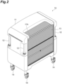
- FIG. 2 is a perspective view illustrating the cart 10 in FIG. 1 .
- FIG. 3 is a bottom view illustrating the cart 10 in FIG. 1 .
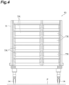
- FIG. 4 is a front view illustrating an example of an internal structure of the cart 10 in FIG. 1 .
- the cart 10 is a truck configured to house articles.
- the cart 10 is a cart unit having a rectangular shape in plan view (when viewed from an upper side).
- the cart 10 is a rectangular dedicated cart configured to carry articles.
- a longitudinal direction of the cart 10 may be simply referred to as a "longitudinal direction”
- a lateral direction of the cart 10 may be simply referred to as a "lateral direction” in some cases.
- the cart 10 has an external shape of a rectangular parallelepiped shape having a width of 800 mm, a length of 900 mm, and a height of 1400 mm.
- the cart 10 can also be used as a hand truck.
- the number of the carts 10 used in the transport system 1 is not particularly limited, and may be 100 to 1000, for example.
- Examples of an article housed in the cart 10 include a specimen, an injection, a sterilizer (a sterilizing container, a recovery container, and the like), and a medical care material (a Medical Engineering (ME) appliance and the like).
- ME Medical Engineering
- the cart 10 includes a housing 11, grips 12, a shutter 13, and casters 14.
- the housing 11 has an external shape of a rectangular box shape.
- An opening 11h is disposed on one side of the housing 11 in the lateral direction.
- An inner part of the housing 11 can be accessed via the opening 11h.
- a plurality of tray receiving hooks configured to hook and support an edge of a tray TR in which an article is put are disposed at appropriate positions.
- a placing board on which an article is placed may be disposed at an appropriate position.
- a plurality of recessed parts 11x with which locating pins 32a (described later) of the automated guided vehicle 30 are engaged are disposed on a bottom surface of the housing 11.
- the recessed parts 11x are disposed at four apex positions (90° rotationally symmetric positions) of a square constituted of sides along the longitudinal direction and the lateral direction on the bottom surface of the housing 11.
- the grip 12 is a portion gripped by a user, for example.
- the grip 12 is a stick-shaped member extending in the upper and lower direction.
- the grips 12 are disposed at positions close to an upper side of a center part in the upper and lower direction at four corners of the housing 11.
- the shutter 13 is disposed to be able to block the opening 11h of the housing 11.
- a vertical shutter is used, in which slats constituted of long and narrow plate members continuously arranged in a bellows shape are housed in an upper part.
- the shutter 13 is caused to be in a closed state by pulling down the slats from an upper side to a lower side, and caused to be in an opened state by lifting up the slats from the lower side to the upper side.
- the casters 14 are disposed at four corners of a lower surface of the housing 11.
- the casters 14 are configured to rotate 360° about an axis along the upper and lower direction.
- a flexible caster is used as the caster 14, for example.
- FIG. 5 is a perspective view illustrating the station 20 in FIG. 1 .
- the station 20 is an area in which the cart 10 is disposed.
- the station 20 is partitioned by a position marker 21 on a floor F.
- the station 20 has a rectangular shape corresponding to the cart 10 in plan view.
- One cart 10 can be disposed at the station 20.
- a plurality of the stations 20 are disposed in one department D (refer to FIG. 1 ), for example.
- the number of the stations 20 disposed in the transport system 1 is not particularly limited.
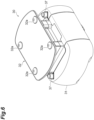
- FIG. 6 is a perspective view illustrating the automated guided vehicle 30 in FIG. 1 .
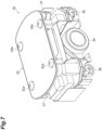
- FIG. 7 is a perspective view illustrating a state in which a cover 31 of the automated guided vehicle 30 in FIG. 1 is removed.
- FIG. 8 is a block diagram illustrating a configuration of the automated guided vehicle 30 in FIG. 1 .
- FIG. 9 is a perspective view illustrating the cart 10 in the case of being transported by the automated guided vehicle 30 in FIG. 1 .
- the automated guided vehicle 30 is a transport vehicle configured to self-travel on the floor F along a predetermined traveling route.
- the automated guided vehicle 30 automatically transports the cart 10 among the stations 20.
- the predetermined traveling route is a route set in advance, and extends to pass through between the departments D.
- the predetermined traveling route is set to be close to the stations 20, for example.
- the automated guided vehicle 30 employs a two-wheel speed difference system as a driving mechanism.
- the automated guided vehicle 30 is configured to be able to perform forward movement, backward movement, a left or right turn, and a spin turn (pivot at the present place).
- the automated guided vehicle 30 has an external shape of a rectangular shape in plan view.
- the automated guided vehicle 30 has an external shape of a rectangular parallelepiped shape having a width of 500 mm, a length of 700 mm, and a height of 320 mm.
- the number of the automated guided vehicles 30 used in the transport system 1 is not particularly limited, and may be 50, for example.
- the traveling direction of the automated guided vehicle 30 may be simply referred to as a "traveling direction" in some cases.
- a direction orthogonal to both of the traveling direction and the upper and lower direction is assumed to be a "right and left direction" in the following description.
- the automated guided vehicle 30 includes a lifting platform 32, an electric cylinder 33, a driving wheel 34, a motor 35, a driven wheel 36, a laser range finder 37, a transport vehicle controller 38, and a communication part 39.
- the lifting platform 32 is a member on which the cart 10 is placed, being configured to be able to be raised or lowered.
- the lifting platform 32 has a plate shape the thickness direction of which is the upper and lower direction.
- the lifting platform 32 is disposed on an upper part of the automated guided vehicle 30.
- the locating pins 32a projecting upward are disposed on an upper surface of the lifting platform 32.
- the locating pin 32a is a projecting part to be engaged with the recessed part 11x on the bottom surface of the cart 10 placed on the lifting platform 32.
- An upper part of the locating pin 32a has a tapered shape tapering toward the upper side.
- the locating pins 32a are disposed at four apex positions (90° rotationally symmetric positions) of a square constituted of sides along the traveling direction and the right and left direction on the upper surface of the lifting platform 32.
- the lifting platform 32 lifts up the cart 10 from below at the time of being raised, and takes down the cart 10 onto the floor F at the time of being lowered.
- the electric cylinder 33 is a driving source configured to raise and lower the lifting platform 32.
- the electric cylinder 33 is connected to the transport vehicle controller 38, and an operation thereof is controlled by the transport vehicle controller 38.
- the driving wheel 34 is a wheel configured to drive the automated guided vehicle 30.
- a pair of the driving wheels 34 is disposed at both end parts in the right and left direction at the center of the automated guided vehicle 30 in the traveling direction.
- the motor 35 is disposed for each driving wheel 34. That is, a pair of the motors 35 is respectively connected to the pair of driving wheels 34, and the pair of motors 35 independently drives the pair of driving wheels 34.
- the motor 35 is connected to the transport vehicle controller 38, and an operation thereof is controlled by the transport vehicle controller 38. For example, by rotationally driving the pair of driving wheels 34 at a constant speed in directions different from each other by the pair of motors 35, a spin turn of the automated guided vehicle 30 is enabled.
- the driven wheel 36 is a wheel configured not to perform driving, and is a wheel configured to be rotated in response to driving of the driving wheel 34.
- Two pairs of the driven wheels 36 are disposed.
- the pair of driving wheels 34 is disposed at both end parts in the right and left direction on one side in the longitudinal direction of the automated guided vehicle 30 in the traveling direction
- the pair of driving wheels 34 is disposed at both end parts in the right and left direction on the other side in the longitudinal direction of the automated guided vehicle 30 in the traveling direction.
- the driven wheel 36 is configured to rotate 360° about the axis along an upper and lower direction, for example.
- the laser range finder 37 is a sensor configured to detect a surrounding environment of the automated guided vehicle 30.
- Laser range finders 37 are disposed on one side and the other side of the automated guided vehicle 30 in the traveling direction. A pair of the laser range finders 37 cooperates with each other to acquire shape data around 360° of the automated guided vehicle 30.
- the laser range finder 37 is not particularly limited, and various sensors can be used as long as the surrounding environment of the automated guided vehicle 30 can be detected.
- the laser range finder 37 is connected to the transport vehicle controller 38, and outputs a detection result thereof to the transport vehicle controller 38.
- the transport vehicle controller 38 collectively controls the automated guided vehicle 30.
- the transport vehicle controller 38 is a computer including a central processing unit (CPU), a read only memory (ROM), a random access memory (RAM), and the like.
- the transport vehicle controller 38 can be configured, for example, as software such that a computer program stored in the ROM is loaded into the RAM to be executed by the CPU.
- the transport vehicle controller 38 may be configured as hardware such as an electronic circuit.
- the transport vehicle controller 38 may be configured with a single device, or may be configured with a plurality of devices. If it is configured with a plurality of devices, they are connected via a communication network such as the Internet or an intranet to logically construct a single transport vehicle controller 38.
- the transport vehicle controller 38 executes traveling control and loading/unloading control for transporting the cart 10 from the station 20 as a transport source to the station 20 as a transport destination based on a transport command received via the communication part 39 from the system controller 40.
- a Simultaneous Localization and Mapping (SLAM) technique is used as a guidance system.
- SLAM Simultaneous Localization and Mapping
- self-position estimation is performed by checking a created environment map against surrounding shape data acquired by the laser range finder 37.
- a difference in self-position estimation from a recognized self-position is received as a correction value, and traveling of the automated guided vehicle 30 is controlled along a traveling route from the self-position reflecting the correction value to a target position.
- the loading/unloading control by raising and lowering the lifting platform 32, loading on the automated guided vehicle 30 and unloading from the automated guided vehicle 30 are performed.
- the communication part 39 is an appliance configured to perform wireless communication with the outside of the automated guided vehicle 30.
- the communication part 39 communicates with the system controller 40 via the access point 50.
- the communication part 39 may include a wireless LAN antenna, for example.
- the electric cylinder 33, the driving wheels 34, the motors 35, the driven wheels 36, the laser range finders 37, the transport vehicle controller 38, and the communication part 39 are covered and protected by the cover 31 (refer to FIG. 6 ).
- the automated guided vehicle 30 gets under the lower part of the cart 10 (between the cart 10 and the floor F) while raising the lifting platform 32 in this state to place the cart 10 on the lifting platform 32 to be lifted up.
- the automated guided vehicle 30 travels in a state of lifting up the cart 10 from below by the lifting platform 32 (state in which the casters 14 are separated from the floor F), and the cart 10 is transported accordingly.
- the automated guided vehicle 30 causes the cart 10 to be grounded on the floor F and takes down the cart 10 from the lifting platform 32.
- the system controller 40 collectively controls the transport system 1.
- the system controller 40 is a computer including a CPU, a ROM, and a RAM.
- the system controller 40 can be configured, for example, as software such that a computer program stored in the ROM is loaded into the RAM to be executed by the CPU.
- the system controller 40 may be configured as hardware such as an electronic circuit.
- the system controller 40 may be configured with a single device or a plurality of devices. In the case of being configured with a plurality of devices, they are connected via a communication network such as the Internet or an intranet to logically construct a single system controller 40.
- the system controller 40 generates a transport command for causing the automated guided vehicle 30 to transport the cart 10 based on an input (transport request) from a host controller (not illustrated) or the operation terminal 60.
- the system controller 40 is installed in a server room, for example.
- the transport command includes a traveling route along which the automated guided vehicle 30 travels. Transport patterns of the transport command include normal transport, circuit transport, and composite transport.
- the normal transport is transport of loading the cart 10 on the automated guided vehicle 30 at the station 20 as a transport source, and unloading the cart 10 from the automated guided vehicle 30 at the station 20 as a transport destination.
- the circuit transport is transport of loading the cart 10 on the automated guided vehicle 30 at the station 20 as a transport source, going around the stations 20 while the cart 10 is loaded thereon, and returning to the station 20 as a transport source thereafter. In the circuit transport, the transport source coincides with the transport destination.
- the composite transport is transport of loading the cart 10 on the automated guided vehicle 30 at the station 20 as a transport source in a first department, moving to a second department, unloading the cart 10 at the station 20 as a transport destination in the second department, loading the cart 10 on the automated guided vehicle 30 at the other station 20 in the second department, returning to the first department, and unloading the cart 10 at the station 20 as a transport destination in the first department.
- the cart 10 may be unloaded at the station 20 as a transport destination in a department other than the first department and the second department.
- the system controller 40 selects an optimum one of the automated guided vehicles 30 using a plurality of conditions, and assigns the transport command to the selected automated guided vehicle 30.
- the conditions for selecting the automated guided vehicle 30 include, for example, the fact that a residual amount of a battery of the automated guided vehicle 30 is equal to or larger than a predetermined value, the fact that a distance from the station 20 as a transport source is the shortest, the fact that the automated guided vehicle 30 is not currently transporting another cart 10, and the like.
- the access point 50 is a relay appliance configured to perform wireless communication between the system controller 40 and the automated guided vehicle 30, and wireless communication between the system controller 40 and the operation terminal 60.
- a frequency band of 2.4 GHz or 5 GHz is used by the access point 50.
- the access point 50 is connected in a wired manner to the system controller 40 via a cable CB.
- the number of the access points 50 installed in the transport system 1 is not particularly limited.
- the access point 50 is disposed on an overhead surface or a wall surface.
- the operation terminal 60 is a terminal configured to receive an input from an operator.
- the operation terminal 60 includes a touch panel. Via the operation terminal 60, the cart 10 as a transport target is input, the station 20 as a transport source is input, and the station 20 as a transport destination is input, for example.
- the operation terminal 60 is installed for each department.
- a portable terminal such as a tablet terminal is used.
- the automated guided vehicle 30 has a total length of a vehicle body shorter than a dimension in the longitudinal direction of the cart 10 in plan view, and a vehicle body width shorter than a dimension in the lateral direction of the cart 10 in plan view.
- a size in the longitudinal direction of the automated guided vehicle 30 is smaller than a size in the longitudinal direction of the cart 10
- a size in the lateral direction of the automated guided vehicle 30 is smaller than a size in the lateral direction of the cart 10.
- the first traveling direction change operation is an operation of changing the traveling direction so that the traveling direction is in parallel with the longitudinal direction of the cart 10 in a state in which the automated guided vehicle 30 gets under the lower part of the cart 10.
- the second traveling direction change operation is an operation of changing the traveling direction so that the traveling direction is in parallel with the lateral direction of the cart 10 in a state in which the automated guided vehicle 30 gets under the lower part of the cart 10.
- control is performed by the transport vehicle controller 38 so that directions of rotational driving of the pair of motors 35 are caused to be opposite to each other, and the pair of driving wheels 34 is rotated at a constant speed in rotational directions opposite to each other. Due to this, a spin turn is performed such that the automated guided vehicle 30 is pivoted at the present place without forward movement and backward movement.
- the automated guided vehicle 30 may be pivoted by 90°.
- a positional relation between a reflector (not illustrated) disposed on the cart 10 and the automated guided vehicle 30 may be grasped based on a detection result of the laser range finder 37, and the automated guided vehicle 30 may be pivoted by an angle with which the traveling direction becomes in parallel with the longitudinal direction or the lateral direction of the cart 10 based on the positional relation.
- the entry operation is an operation in which the automated guided vehicle 30 enters the lower part of the cart 10 from one side or the other side in the lateral direction of the cart 10 to get under the lower part of the cart 10.
- the entry operation is an operation in which the automated guided vehicle 30 enters the lower part of the cart 10 from a long side of the cart 10 to get under the lower part of the cart 10.
- the coming-out operation is an operation in which the automated guided vehicle 30 being under the lower part of the cart 10 comes out from one side or the other side in the lateral direction of the lower part of the cart 10.
- the coming-out operation is an operation in which the automated guided vehicle 30 being under the lower part of the cart 10 comes out from the long side of the lower part of the cart 10 to the outside of the lower part of the cart 10.
- the automated guided vehicle 30 performs an operation described below at the time of carrying out the cart 10 from the station 20.
- the station 20 as a transport source has a configuration in which one side and the other side in the longitudinal direction of the station 20 are blocked by obstacles B, and the automated guided vehicle 30 cannot enter from the longitudinal direction.
- Whether the obstacle B is present around the station 20 can be determined, for example, based on information about each station 20, which is stored in advance in the system controller 40 (the same applies to the following description).
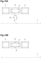
- driving of each of the pair of motors 35 is controlled by the transport vehicle controller 38, and the automated guided vehicle 30 travels from a predetermined traveling route 2 toward the station 20.
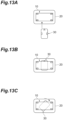
- driving of each of the pair of motors 35 is controlled by the transport vehicle controller 38, and the automated guided vehicle 30 performs the entry operation to enter the lower part of the cart 10 disposed at the station 20.
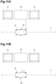
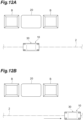
- driving of the electric cylinder 33 is controlled by the transport vehicle controller 38 to raise the lifting platform 32, and the automated guided vehicle 30 places the cart 10 on the lifting platform 32 to lift it up. Due to this, the automated guided vehicle 30 is connected to the cart 10 again. As illustrated in FIG. 12(b) , driving of each of the pair of motors 35 is then controlled by the transport vehicle controller 38, and the automated guided vehicle 30 travels toward the transport destination along the predetermined traveling route 2 together with the connected cart 10.
- the automated guided vehicle 30 performs an operation described below at the time of carrying out the cart 10 from the station 20.
- the station 20 as a transport source has a configuration in which one side and the other side in the longitudinal direction of the station 20 are not blocked, and the automated guided vehicle 30 can enter from the longitudinal direction.
- driving of each of the pair of motors 35 is controlled by the transport vehicle controller 38, and the automated guided vehicle 30 travels toward the station 20.
- driving of each of the pair of motors 35 is controlled by the transport vehicle controller 38, and the automated guided vehicle 30 performs the entry operation to enter the lower part of the cart 10 disposed at the station 20.
- driving of the electric cylinder 33 is controlled by the transport vehicle controller 38 to raise the lifting platform 32, and the automated guided vehicle 30 places the cart 10 on the lifting platform 32 to lift it up. Due to this, the automated guided vehicle 30 is connected to the cart 10.
- driving of each of the pair of motors 35 is controlled by the transport vehicle controller 38, and the automated guided vehicle 30 travels in the longitudinal direction of the station 20 together with the connected cart 10 to come out from the station 20.
- Driving of each of the pair of motors 35 is then controlled by the transport vehicle controller 38, and the automated guided vehicle 30 travels toward the transport destination together with the connected cart 10. Thereafter, the cart 10 and the automated guided vehicle 30 travel while smoothly changing orientations thereof along the predetermined traveling route 2.
- the automated guided vehicle 30 performs an operation described below at the time of carrying the cart 10 into the station 20.
- the station 20 as a transport source has a configuration in which one side and the other side in the longitudinal direction of the station 20 are blocked by the obstacles B, and the automated guided vehicle 30 cannot enter from the longitudinal direction.
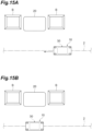
- the automated guided vehicle 30 travels along the predetermined traveling route 2 together with the cart 10 connected to the automated guided vehicle 30, and stops at a position close to the station 20 as illustrated in FIG. 15(b) .
- the cart 10 is transported so that the longitudinal direction thereof is in parallel with the traveling direction.
- a stop position of the automated guided vehicle 30 is not particularly limited, but is a position where a line connecting the center of the station 20 with the center of the cart 10 is orthogonal to the predetermined traveling route 2.
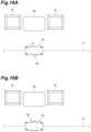
- driving of the electric cylinder 33 is controlled by the transport vehicle controller 38 to raise the lifting platform 32, and the automated guided vehicle 30 places the cart 10 on the lifting platform 32 to lift it up. Due to this, the automated guided vehicle 30 is connected to the cart 10 again. Thereafter, as illustrated in FIG. 17(a) , driving of each of the pair of motors 35 is controlled by the transport vehicle controller 38, and the automated guided vehicle 30 travels toward the station 20 along the lateral direction of the station 20 together with the connected cart 10 to enter the station 20.
- driving of the electric cylinder 33 is controlled by the transport vehicle controller 38 to lower the lifting platform 32, and the automated guided vehicle 30 takes down the cart 10 from the lifting platform 32 to the floor F in the station 20. Due to this, the automated guided vehicle 30 is disconnected from the cart 10, and the cart 10 is completely carried into the station 20. Subsequently, as illustrated in FIG. 17(b) , driving of each of the pair of motors 35 is controlled by the transport vehicle controller 38, and the automated guided vehicle 30 performs the coming-out operation to come out from the lower side of the cart 10 and the station 20. Thereafter, for example, another command is assigned to the automated guided vehicle 30 by the system controller 40.
- the automated guided vehicle 30 performs an operation described below at the time of carrying out the cart 10 from the station 20.
- the station 20 as a transport destination has a configuration in which one side and the other side in the longitudinal direction of the station 20 are not blocked, and the automated guided vehicle 30 can enter from the longitudinal direction.
- driving of each of the pair of motors 35 is controlled by the transport vehicle controller 38, and the automated guided vehicle 30 travels from the predetermined traveling route 2 toward the station 20 while smoothly changing the orientation thereof together with the cart 10 connected to the automated guided vehicle 30 to enter the station 20 in parallel therewith as illustrated in FIG. 18(b) .
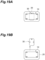
- driving of the electric cylinder 33 is controlled by the transport vehicle controller 38 to lower the lifting platform 32, and the automated guided vehicle 30 takes down the cart 10 from the lifting platform 32 to the floor F. Due to this, the automated guided vehicle 30 is disconnected from the cart 10.
- the longitudinal direction of the cart 10 transported by the automated guided vehicle 30 can be caused to be in parallel with the traveling direction by the first traveling direction change operation.
- a length of the cart 10 in a width direction of the passage can be reduced.
- the automated guided vehicle 30 that is transporting the cart 10 can be prevented from hindering traffic.
- the automated guided vehicle 30 performs the entry operation of entering the lower part of the cart 10 from one side or the other side in the lateral direction. Due to this, the automated guided vehicle 30 can smoothly enter the lower part of the cart 10.
- the automated guided vehicle 30 performs the entry operation of entering the lower part of the cart 10 disposed at the station 20, performs the first traveling direction change operation, makes connection with the cart 10 by raising the lifting platform 32 and placing the cart 10 on the lifting platform 32, and comes out from the station 20 together with the cart 10.
- the cart 10 can be easily carried out from the station 20 around which no obstacle is present.
- the automated guided vehicle 30 performs the entry operation of entering the lower part of the cart 10 disposed at the station 20, makes connection with the cart 10 by raising the lifting platform 32 and placing the cart 10 on the lifting platform 32, comes out from the station 20 together with the cart 10, disconnects the cart 10 by lowering the lifting platform 32 and taking down the cart 10 from the lifting platform 32, performs the first traveling direction change operation, and makes connection with the cart 10 by raising the lifting platform 32 and placing the cart 10 on the lifting platform 32.
- the automated guided vehicle 30 can change a holding manner for the transported cart 10.
- the cart 10 can be easily carried out from the station 20 around which the obstacle B is present.
- the station 20 is not limited to a station in which one side or the other side in the longitudinal direction is opened, so that a degree of freedom of a disposition place of the station 20 can be enhanced.
- the automated guided vehicle 30 performs the second traveling direction change operation of changing the traveling direction of the automated guided vehicle 30 so that the traveling direction of the automated guided vehicle 30 is in parallel with the lateral direction of the cart 10 in a state of being under the lower part of the cart 10. Due to this, the automated guided vehicle 30 can easily carry the cart 10 into the station 20 of various aspects by using the second traveling direction change operation.
- the automated guided vehicle 30 performs the coming-out operation of coming out from one side or the other side in the lateral direction of the lower part of the cart 10. Due to this, the automated guided vehicle 30 can smoothly come out from the lower part of the cart 10.
- the automated guided vehicle 30 In the transport system 1, in the case of the automated guided vehicle 30 connected to the cart 10 by placing the cart 10 on the lifting platform 32 so that the traveling direction of the automated guided vehicle 30 is in parallel with the longitudinal direction of the cart 10, such an automated guided vehicle 30 carries the cart 10 into the station 20 around which the obstacle B is not present, the automated guided vehicle 30 enters the station 20 together with the cart 10, disconnects the cart 10 by lowering the lifting platform 32 and taking down the cart 10 from the lifting platform 32, performs the second traveling direction change operation, and performs the coming-out operation to come out from the station 20.
- the cart 10 in the transport system 1, while the longitudinal direction of the cart 10 transported by the automated guided vehicle 30 is caused to be in parallel with the traveling direction, the cart 10 can be easily carried into the station 20 around which the obstacle B is not present.
- the automated guided vehicle 30 may disconnect the cart 10 by lowering the lifting platform 32 and taking down the cart 10 from the lifting platform 32, perform the second traveling direction change operation, make connection with the cart 10 by raising the lifting platform 32 and placing the cart 10 on the lifting platform 32, enter the station 20 together with the cart 10, disconnect the cart 10 by lowering the lifting platform 32 and taking down the cart 10 from the lifting platform 32, and perform the coming-out operation to come out from the station 20.
- the automated guided vehicle 30 can change a holding manner for the transported cart 10. While the longitudinal direction of the cart 10 transported by the automated guided vehicle 30 is caused to be in parallel with the traveling direction, the cart 10 can be easily carried into the station 20 around which the obstacle B is present.
- the station 20 is not limited to a station in which one side or the other side in the lateral direction is opened, so that a degree of freedom of a disposition place of the station 20 can be enhanced.
- the transport system 1 performs a spin turn of pivoting the automated guided vehicle 30 at the present place.
- the traveling direction of the automated guided vehicle 30 can be caused to be in parallel with the longitudinal direction of the cart 10 by using the spin turn.
- the transport system 1 performs a spin turn of pivoting the automated guided vehicle 30 at the present place.
- the traveling direction of the automated guided vehicle 30 can be caused to be in parallel with the lateral direction of the cart 10 by using the spin turn.
- the transported object is the cart 10. The effect described above can be exhibited in the transport system 1 in which the cart 10 is transported by the automated guided vehicle 30.
- the automated guided vehicle 30 can cause the longitudinal direction of the transported cart 10 to be in parallel with the traveling direction by the first traveling direction change operation.
- a length of the cart 10 in a width direction of the passage can be reduced.
- the automated guided vehicle 30 that is transporting the cart 10 can be prevented from hindering traffic.
- the longitudinal direction of the cart 10 transported by the automated guided vehicle 30 can be caused to be in parallel with the traveling direction at the first traveling direction change step.
- a length of the cart 10 in a width direction of the passage can be reduced.
- the automated guided vehicle 30 that is transporting the cart 10 can be prevented from hindering traffic.
- the automated guided vehicle 30 and the cart 10 can be positioned and sliding in the lateral direction can be suppressed.
- the locating pins 32a and the recessed parts 11x are disposed at symmetric positions in a forward and backward direction and a left and right direction (90° rotationally symmetric positions), so that they can be engaged with each other all times in the case of the automated guided vehicle 30 being oriented in any of the forward and backward direction and the left and right direction of the cart 10.
- the first traveling direction change operation is performed on the predetermined traveling route 2, but the embodiment is not limited thereto.
- the first traveling direction change operation may be performed during a period from when the automated guided vehicle 30 enters the station 20 from the predetermined traveling route 2 until the automated guided vehicle 30 returns to the predetermined traveling route 2 from the station 20.
- the automated guided vehicle 30 may perform the first traveling direction change operation at a position between the station 20 and the predetermined traveling route 2, and return to the predetermined traveling route 2 together with the connected cart 10 to travel along the predetermined traveling route 2 toward the transport destination thereafter.
- the automated guided vehicle 30 after the automated guided vehicle 30 enters the station 20 and returns to the predetermined traveling route 2, the first traveling direction change operation has been already performed and the longitudinal direction of the cart 10 is in parallel with the traveling direction, so that the automated guided vehicle 30 can be securely prevented from hindering traffic on the predetermined traveling route 2.
- the cart 10 is provided as the transported object.
- the transported object is not particularly limited, and may be various objects.
- the transport system 1 is applied to automatic transportation of the cart 10 among the departments D, but a field to which an aspect of the present invention is applied is not particularly limited. An aspect of the present invention can be applied to various fields.
- a transport system including:
- An automated guided vehicle including a lifting platform on which a transported object having a long shape in plan view is placed, the automated guided vehicle being configured to self-travel along a predetermined traveling route, wherein the automated guided vehicle
- a method for controlling an operation of an automated guided vehicle including a lifting platform on which a transported object having a long shape in plan view is placed, the automated guided vehicle being configured to self-travel along a predetermined traveling route, wherein
Landscapes
- Engineering & Computer Science (AREA)
- Automation & Control Theory (AREA)
- Remote Sensing (AREA)
- Physics & Mathematics (AREA)
- General Physics & Mathematics (AREA)
- Aviation & Aerospace Engineering (AREA)
- Radar, Positioning & Navigation (AREA)
- Structural Engineering (AREA)
- Transportation (AREA)
- Civil Engineering (AREA)
- Life Sciences & Earth Sciences (AREA)
- Geology (AREA)
- Mechanical Engineering (AREA)
- Control Of Position, Course, Altitude, Or Attitude Of Moving Bodies (AREA)
- Platform Screen Doors And Railroad Systems (AREA)
Abstract

Description
- An aspect of the present invention relates to a transport system, an automated guided vehicle, and a method for controlling the automated guided vehicle.
- There is known a transport system including: a transported object; a station at which the transported object is disposed; and an automated guided vehicle including a lifting platform on which the transported object is placed, the automated guided vehicle being configured to self-travel along a predetermined traveling route. As this type of technique, for example, Patent Literature 1 discloses a system including an unmanned vehicle configured to get under a wagon truck (transported object) to lift up the wagon truck, the system configured to transport the wagon truck by the unmanned vehicle to a destination instructed from the outside.
- [Patent Literature 1]
Japanese Unexamined Patent Publication No. H9-185413 - In the transport system as described above, a transported object having a long shape in plan view may be transported while being placed on the lifting platform of the automated guided vehicle in some cases. In this case, for example, in the case of the automated guided vehicle traveling through a narrow passage, if the transported object is placed on the lifting platform so that a longitudinal direction of the transported object coincides with a width direction of the passage, a problem may be caused such that a large part of the passage is blocked and traffic tends to be hindered.
- An object of an aspect of the present invention is to provide a transport system, an automated guided vehicle, and a method for controlling the automated guided vehicle with which the automated guided vehicle that is transporting the transported object can be prevented from hindering traffic.
- A transport system according to an aspect of the present invention includes: a transported object having a long shape in plan view; a station at which the transported object is disposed; and an automated guided vehicle including a lifting platform on which the transported object is placed, the automated guided vehicle being configured to self-travel along a predetermined traveling route. The automated guided vehicle has a total length of a vehicle body shorter than a dimension in a longitudinal direction of the transported object in plan view, and a vehicle body width shorter than a dimension in a lateral direction of the transported object in plan view, and performs a first traveling direction change operation of changing a traveling direction of the automated guided vehicle so that the traveling direction of the automated guided vehicle is in parallel with the longitudinal direction of the transported object in a state of being under a lower part of the transported object.
- In this transport system, the longitudinal direction of the transported object transported by the automated guided vehicle can be caused to be in parallel with the traveling direction of the automated guided vehicle (hereinafter, also simply referred to as a "traveling direction") by the first traveling direction change operation. Thus, for example, even in the case of the automated guided vehicle traveling in a narrow passage, a length of the transported object in a width direction of the passage can be reduced. As a result, the automated guided vehicle that is transporting the transported object can be prevented from hindering traffic.
- In the transport system according to an aspect of the present invention, the first traveling direction change operation may be performed during a period from when the automated guided vehicle enters the station from the predetermined traveling route until the automated guided vehicle returns to the predetermined traveling route from the station. In this case, after the automated guided vehicle enters the station and returns to the predetermined traveling route, the first traveling direction change operation has been already performed and the longitudinal direction of the transported object is in parallel with the traveling direction, so that the automated guided vehicle can be securely prevented from hindering traffic. Herein, the predetermined traveling route may be a route that is planned every time the automated guided vehicle performs automatic traveling on a route from the present location to a destination, or may be a route that is planned by a user of the automated guided vehicle or the transport system to be continuously used thereafter.
- In the transport system according to an aspect of the present invention, the automated guided vehicle may perform an entry operation of entering the lower part of the transported object from one side or the other side in the lateral direction. Due to this, the automated guided vehicle can smoothly enter the lower part of the transported object.
- In the transport system according to an aspect of the present invention, in the case of carrying out the transported object from the station, the automated guided vehicle may perform the entry operation of entering the lower part of the transported object disposed at the station, perform the first traveling direction change operation, make connection with the transported object by raising the lifting platform and placing the transported object on the lifting platform, and come out from the station together with the transported object. In this case, while the longitudinal direction of the transported object transported by the automated guided vehicle is caused to be in parallel with the traveling direction, the transported object can be easily carried out from the station around which no obstacle is present.
- In the transport system according to an aspect of the present invention, in the case of carrying out the transported object from the station, the automated guided vehicle may perform the entry operation of entering the lower part of the transported object disposed at the station, make connection with the transported object by raising the lifting platform and placing the transported object on the lifting platform, come out from the station together with the transported object, disconnect the transported object by lowering the lifting platform and taking down the transported object from the lifting platform, perform the first traveling direction change operation, and make connection with the transported object by raising the lifting platform and placing the transported object on the lifting platform. In this case, while the longitudinal direction of the transported object transported by the automated guided vehicle is caused to be in parallel with the traveling direction, the transported object can be easily carried out from the station around which an obstacle is present.
- In the transport system according to an aspect of the present invention, a spin turn may be performed to pivot the automated guided vehicle at a present place in the first traveling direction change operation. In this case, the traveling direction of the automated guided vehicle can be caused to be in parallel with the longitudinal direction of the transported object by using the spin turn.
- In the transport system according to an aspect of the present invention, the automated guided vehicle may perform a second traveling direction change operation of changing the traveling direction of the automated guided vehicle so that the traveling direction of the automated guided vehicle is in parallel with the lateral direction of the transported object in a state of being under the lower part of the transported object. Due to this, the automated guided vehicle can easily carry the transported object into stations of various aspects by using the second traveling direction change operation.
- In the transport system according to an aspect of the present invention, the automated guided vehicle may perform a coming-out operation of coming out from one side or the other side in the lateral direction of the lower part of the transported object. Due to this, the automated guided vehicle can smoothly come out from the lower part of the transported object.
- In the transport system according to an aspect of the present invention, in the case of the automated guided vehicle connected to the transported object by placing the transported object on the lifting platform so that the traveling direction of the automated guided vehicle is in parallel with the longitudinal direction of the transported object, in the case that such an automated guided vehicle carries the transported object into the station, the automated guided vehicle may enter the station together with the transported object, disconnect the transported object by lowering the lifting platform and taking down the transported object from the lifting platform, perform the second traveling direction change operation, and perform the coming-out operation to come out from the station. In this case, while the longitudinal direction of the transported object transported by the automated guided vehicle is caused to be in parallel with the traveling direction, the transported object can be easily carried into the station around which no obstacle is present.
- In the transport system according to an aspect of the present invention, in the case of the automated guided vehicle connected to the transported object by placing the transported object on the lifting platform so that the traveling direction of the automated guided vehicle is in parallel with the longitudinal direction of the transported object, in the case that such an automated guided vehicle carries the transported object into the station, the automated guided vehicle may disconnect the transported object by lowering the lifting platform and taking down the transported object from the lifting platform, perform the second traveling direction change operation, make connection with the transported object by raising the lifting platform and placing the transported object on the lifting platform, enter the station together with the transported object, disconnect the transported object by lowering the lifting platform and taking down the transported object from the lifting platform, and perform the coming-out operation to come out from the station. In this case, while the longitudinal direction of the transported object transported by the automated guided vehicle is caused to be in parallel with the traveling direction, the transported object can be easily carried into the station around which an obstacle is present.
- In the transport system according to an aspect of the present invention, a spin turn may be performed to pivot the automated guided vehicle at a present place in the second traveling direction change operation. In this case, the traveling direction of the automated guided vehicle can be caused to be in parallel with the lateral direction of the transported object by using the spin turn.
- In the transport system according to an aspect of the present invention, the transported object may be a cart configured to carry articles. In this case, the effect described above can be exhibited in the system in which the cart is transported by the automated guided vehicle.
- The automated guided vehicle according to an aspect of the present invention is an automated guided vehicle including a lifting platform on which a transported object having a long shape in plan view is placed, the automated guided vehicle being configured to self-travel along a predetermined traveling route. The automated guided vehicle has a total length of a vehicle body shorter than a dimension in a longitudinal direction of the transported object in plan view, and a vehicle body width shorter than a dimension in a lateral direction of the transported object in plan view, and performs a first traveling direction change operation of changing a traveling direction of the automated guided vehicle so that the traveling direction of the automated guided vehicle is in parallel with the longitudinal direction of the transported object in a state of being under a lower part of the transported object.
- With this automated guided vehicle, the longitudinal direction of the transported object to be transported can be caused to be in parallel with the traveling direction by the first traveling direction change operation. The automated guided vehicle that is transporting the transported object can be prevented from hindering traffic.
- A method for controlling the automated guided vehicle according to an aspect of the present invention is a method for controlling an operation of an automated guided vehicle including a lifting platform on which a transported object having a long shape in plan view is placed, the automated guided vehicle being configured to self-travel along a predetermined traveling route, in which the automated guided vehicle has a total length of a vehicle body shorter than a dimension in a longitudinal direction of the transported object in plan view, and a vehicle body width shorter than a dimension in a lateral direction of the transported object in plan view, and the method includes a first traveling direction change step of changing a traveling direction of the automated guided vehicle so that the traveling direction of the automated guided vehicle is in parallel with the longitudinal direction of the transported object in a state in which the automated guided vehicle is under a lower part of the transported object.
- In this method for controlling the automated guided vehicle, the longitudinal direction of the transported object transported by the automated guided vehicle can be caused to be in parallel with the traveling direction at the first traveling direction change step. The automated guided vehicle that is transporting the transported object can be prevented from hindering traffic.
- According to an aspect of the present invention, it is possible to provide a transport system, an automated guided vehicle, and a method for controlling the automated guided vehicle with which the automated guided vehicle that is transporting a transported object can be prevented from hindering traffic.
-
- [
FIG. 1] FIG. 1 is a schematic configuration diagram illustrating a transport system according to an embodiment. - [
FIG. 2] FIG. 2 is a perspective view illustrating a cart inFIG. 1 . - [
FIG. 3] FIG. 3 is a bottom view illustrating the cart inFIG. 1 . - [
FIG. 4] FIG. 4 is a front view illustrating an example of an internal structure of the cart inFIG. 1 . - [
FIG. 5] FIG. 5 is a perspective view illustrating a station inFIG. 1 . - [
FIG. 6] FIG. 6 is a perspective view illustrating an automated guided vehicle inFIG. 1 . - [
FIG. 7] FIG. 7 is a perspective view illustrating a state in which a cover of the automated guided vehicle inFIG. 1 is removed. - [
FIG. 8] FIG. 8 is a block diagram illustrating a configuration of the automated guided vehicle inFIG. 1 . - [
FIG. 9] FIG. 9 is a perspective view illustrating the cart in the case of being transported by the automated guided vehicle inFIG. 1 . - [
FIG. 10] FIG. 10(a) is a schematic bird's-eye view for explaining an operation example of the automated guided vehicle at the time of carrying out the cart from the station.FIG. 10(b) is a schematic bird's-eye view illustrating a continuation ofFIG. 10(a) . - [
FIG. 11] FIG. 11(a) is a schematic bird's-eye view illustrating a continuation ofFIG. 10(b) .FIG. 11(b) is a schematic bird's-eye view illustrating a continuation ofFIG. 11(a) . - [
FIG. 12] FIG. 12(a) is a schematic bird's-eye view illustrating a continuation ofFIG. 11(b) .FIG. 12(b) is a schematic bird's-eye view illustrating a continuation ofFIG. 12(a) . - [
FIG. 13] FIG. 13(a) is a schematic bird's-eye view for explaining another operation example of the automated guided vehicle at the time of carrying out the cart from the station.FIG. 13(b) is a schematic bird's-eye view illustrating a continuation ofFIG. 13(a). FIG. 13(c) is a schematic bird's-eye view illustrating a continuation ofFIG. 13(b) . - [
FIG. 14] FIG. 14(a) is a schematic bird's-eye view illustrating a continuation ofFIG. 13(c) .FIG. 14(b) is a schematic bird's-eye view illustrating a continuation ofFIG. 14(a) . - [
FIG. 15] FIG. 15(a) is a schematic bird's-eye view for explaining an operation example of the automated guided vehicle at the time of carrying the cart into the station.FIG. 15(b) is a schematic bird's-eye view illustrating a continuation ofFIG. 15(a) . - [
FIG. 16] FIG. 16(a) is a schematic bird's-eye view illustrating a continuation ofFIG. 15(b) .FIG. 16(b) is a schematic bird's-eye view illustrating a continuation ofFIG. 16(a) . - [
FIG. 17] FIG. 17(a) is a schematic bird's-eye view illustrating a continuation ofFIG. 16(b) .FIG. 17(b) is a schematic bird's-eye view illustrating a continuation ofFIG. 17(a) . - [
FIG. 18] FIG. 18(a) is a schematic bird's-eye view for explaining another operation example of the automated guided vehicle at the time of carrying the cart into the station.FIG. 18(b) is a schematic bird's-eye view illustrating a continuation ofFIG. 18(a). FIG. 18(c) is a schematic bird's-eye view illustrating a continuation ofFIG. 18(b) . - [
FIG. 19] FIG. 19(a) is a schematic bird's-eye view illustrating a continuation ofFIG. 18(c) .FIG. 19(b) is a schematic bird's-eye view illustrating a continuation ofFIG. 19(a) . - An embodiment will now be described with reference to the drawings. In description of the drawings, like elements are designated by like reference signs, and duplicate description is omitted. The words "upper" and "lower" correspond to an upper and lower direction in a vertical direction.
-
FIG. 1 is a schematic configuration diagram illustrating a transport system 1 according to the embodiment. As illustrated inFIG. 1 , the transport system 1 is a system that is installed inside a building such as a hospital, for example, and achieves automatic transportation of a cart (transported object) 10 among a plurality of departments D. The transport system 1 includes a plurality ofcarts 10, a plurality ofstations 20, a plurality of automated guidedvehicles 30, asystem controller 40, a plurality ofaccess points 50, and a plurality ofoperation terminals 60. -
FIG. 2 is a perspective view illustrating thecart 10 inFIG. 1 .FIG. 3 is a bottom view illustrating thecart 10 inFIG. 1 .FIG. 4 is a front view illustrating an example of an internal structure of thecart 10 inFIG. 1 . As illustrated inFIG. 2 andFIG. 4 , thecart 10 is a truck configured to house articles. Thecart 10 is a cart unit having a rectangular shape in plan view (when viewed from an upper side). In other words, thecart 10 is a rectangular dedicated cart configured to carry articles. Hereinafter, a longitudinal direction of thecart 10 may be simply referred to as a "longitudinal direction", and a lateral direction of thecart 10 may be simply referred to as a "lateral direction" in some cases. - For example, the
cart 10 has an external shape of a rectangular parallelepiped shape having a width of 800 mm, a length of 900 mm, and a height of 1400 mm. Thecart 10 can also be used as a hand truck. The number of thecarts 10 used in the transport system 1 is not particularly limited, and may be 100 to 1000, for example. Examples of an article housed in thecart 10 include a specimen, an injection, a sterilizer (a sterilizing container, a recovery container, and the like), and a medical care material (a Medical Engineering (ME) appliance and the like). - The
cart 10 includes ahousing 11, grips 12, ashutter 13, andcasters 14. Thehousing 11 has an external shape of a rectangular box shape. Anopening 11h is disposed on one side of thehousing 11 in the lateral direction. An inner part of thehousing 11 can be accessed via theopening 11h. Inside thehousing 11, for example, a plurality of tray receiving hooks configured to hook and support an edge of a tray TR in which an article is put are disposed at appropriate positions. Inside thehousing 11, a placing board on which an article is placed may be disposed at an appropriate position. As illustrated inFIG. 3 , on a bottom surface of thehousing 11, a plurality of recessedparts 11x with which locating pins 32a (described later) of the automated guidedvehicle 30 are engaged are disposed. The recessedparts 11x are disposed at four apex positions (90° rotationally symmetric positions) of a square constituted of sides along the longitudinal direction and the lateral direction on the bottom surface of thehousing 11. - As illustrated in
FIG. 2 , thegrip 12 is a portion gripped by a user, for example. Thegrip 12 is a stick-shaped member extending in the upper and lower direction. Thegrips 12 are disposed at positions close to an upper side of a center part in the upper and lower direction at four corners of thehousing 11. Theshutter 13 is disposed to be able to block theopening 11h of thehousing 11. As theshutter 13, for example, a vertical shutter is used, in which slats constituted of long and narrow plate members continuously arranged in a bellows shape are housed in an upper part. Theshutter 13 is caused to be in a closed state by pulling down the slats from an upper side to a lower side, and caused to be in an opened state by lifting up the slats from the lower side to the upper side. Thecasters 14 are disposed at four corners of a lower surface of thehousing 11. Thecasters 14 are configured to rotate 360° about an axis along the upper and lower direction. As thecaster 14, for example, a flexible caster is used. -
FIG. 5 is a perspective view illustrating thestation 20 inFIG. 1 . As illustrated inFIG. 5 , thestation 20 is an area in which thecart 10 is disposed. Thestation 20 is partitioned by aposition marker 21 on a floor F. Thestation 20 has a rectangular shape corresponding to thecart 10 in plan view. Onecart 10 can be disposed at thestation 20. A plurality of thestations 20 are disposed in one department D (refer toFIG. 1 ), for example. The number of thestations 20 disposed in the transport system 1 is not particularly limited. -
FIG. 6 is a perspective view illustrating the automated guidedvehicle 30 inFIG. 1 .FIG. 7 is a perspective view illustrating a state in which acover 31 of the automated guidedvehicle 30 inFIG. 1 is removed.FIG. 8 is a block diagram illustrating a configuration of the automated guidedvehicle 30 inFIG. 1 .FIG. 9 is a perspective view illustrating thecart 10 in the case of being transported by the automated guidedvehicle 30 inFIG. 1 . As illustrated inFIG. 6 , the automated guidedvehicle 30 is a transport vehicle configured to self-travel on the floor F along a predetermined traveling route. The automated guidedvehicle 30 automatically transports thecart 10 among thestations 20. The predetermined traveling route is a route set in advance, and extends to pass through between the departments D. The predetermined traveling route is set to be close to thestations 20, for example. - The automated guided
vehicle 30 employs a two-wheel speed difference system as a driving mechanism. The automated guidedvehicle 30 is configured to be able to perform forward movement, backward movement, a left or right turn, and a spin turn (pivot at the present place). The automated guidedvehicle 30 has an external shape of a rectangular shape in plan view. For example, the automated guidedvehicle 30 has an external shape of a rectangular parallelepiped shape having a width of 500 mm, a length of 700 mm, and a height of 320 mm. The number of the automated guidedvehicles 30 used in the transport system 1 is not particularly limited, and may be 50, for example. Hereinafter, the traveling direction of the automated guidedvehicle 30 may be simply referred to as a "traveling direction" in some cases. A direction orthogonal to both of the traveling direction and the upper and lower direction is assumed to be a "right and left direction" in the following description. - As illustrated in
FIG. 7 andFIG. 8 , the automated guidedvehicle 30 includes alifting platform 32, anelectric cylinder 33, adriving wheel 34, amotor 35, a drivenwheel 36, alaser range finder 37, atransport vehicle controller 38, and acommunication part 39. - The
lifting platform 32 is a member on which thecart 10 is placed, being configured to be able to be raised or lowered. Thelifting platform 32 has a plate shape the thickness direction of which is the upper and lower direction. Thelifting platform 32 is disposed on an upper part of the automated guidedvehicle 30. The locating pins 32a projecting upward are disposed on an upper surface of thelifting platform 32. The locatingpin 32a is a projecting part to be engaged with the recessedpart 11x on the bottom surface of thecart 10 placed on thelifting platform 32. An upper part of the locatingpin 32a has a tapered shape tapering toward the upper side. The locating pins 32a are disposed at four apex positions (90° rotationally symmetric positions) of a square constituted of sides along the traveling direction and the right and left direction on the upper surface of thelifting platform 32. Thelifting platform 32 lifts up thecart 10 from below at the time of being raised, and takes down thecart 10 onto the floor F at the time of being lowered. Theelectric cylinder 33 is a driving source configured to raise and lower thelifting platform 32. Theelectric cylinder 33 is connected to thetransport vehicle controller 38, and an operation thereof is controlled by thetransport vehicle controller 38. - The
driving wheel 34 is a wheel configured to drive the automated guidedvehicle 30. A pair of the drivingwheels 34 is disposed at both end parts in the right and left direction at the center of the automated guidedvehicle 30 in the traveling direction. Themotor 35 is disposed for eachdriving wheel 34. That is, a pair of themotors 35 is respectively connected to the pair of drivingwheels 34, and the pair ofmotors 35 independently drives the pair of drivingwheels 34. Themotor 35 is connected to thetransport vehicle controller 38, and an operation thereof is controlled by thetransport vehicle controller 38. For example, by rotationally driving the pair of drivingwheels 34 at a constant speed in directions different from each other by the pair ofmotors 35, a spin turn of the automated guidedvehicle 30 is enabled. - The driven
wheel 36 is a wheel configured not to perform driving, and is a wheel configured to be rotated in response to driving of thedriving wheel 34. Two pairs of the drivenwheels 36 are disposed. Specifically, the pair of drivingwheels 34 is disposed at both end parts in the right and left direction on one side in the longitudinal direction of the automated guidedvehicle 30 in the traveling direction, and the pair of drivingwheels 34 is disposed at both end parts in the right and left direction on the other side in the longitudinal direction of the automated guidedvehicle 30 in the traveling direction. The drivenwheel 36 is configured to rotate 360° about the axis along an upper and lower direction, for example. - The
laser range finder 37 is a sensor configured to detect a surrounding environment of the automated guidedvehicle 30.Laser range finders 37 are disposed on one side and the other side of the automated guidedvehicle 30 in the traveling direction. A pair of thelaser range finders 37 cooperates with each other to acquire shape data around 360° of the automated guidedvehicle 30. Thelaser range finder 37 is not particularly limited, and various sensors can be used as long as the surrounding environment of the automated guidedvehicle 30 can be detected. Thelaser range finder 37 is connected to thetransport vehicle controller 38, and outputs a detection result thereof to thetransport vehicle controller 38. - The
transport vehicle controller 38 collectively controls the automated guidedvehicle 30. Thetransport vehicle controller 38 is a computer including a central processing unit (CPU), a read only memory (ROM), a random access memory (RAM), and the like. Thetransport vehicle controller 38 can be configured, for example, as software such that a computer program stored in the ROM is loaded into the RAM to be executed by the CPU. Thetransport vehicle controller 38 may be configured as hardware such as an electronic circuit. Thetransport vehicle controller 38 may be configured with a single device, or may be configured with a plurality of devices. If it is configured with a plurality of devices, they are connected via a communication network such as the Internet or an intranet to logically construct a singletransport vehicle controller 38. - The
transport vehicle controller 38 executes traveling control and loading/unloading control for transporting thecart 10 from thestation 20 as a transport source to thestation 20 as a transport destination based on a transport command received via thecommunication part 39 from thesystem controller 40. In the traveling control, a Simultaneous Localization and Mapping (SLAM) technique is used as a guidance system. In the traveling control, self-position estimation is performed by checking a created environment map against surrounding shape data acquired by thelaser range finder 37. In the traveling control, a difference in self-position estimation from a recognized self-position is received as a correction value, and traveling of the automated guidedvehicle 30 is controlled along a traveling route from the self-position reflecting the correction value to a target position. In the loading/unloading control, by raising and lowering thelifting platform 32, loading on the automated guidedvehicle 30 and unloading from the automated guidedvehicle 30 are performed. - The
communication part 39 is an appliance configured to perform wireless communication with the outside of the automated guidedvehicle 30. Thecommunication part 39 communicates with thesystem controller 40 via theaccess point 50. Thecommunication part 39 may include a wireless LAN antenna, for example. In the automated guidedvehicle 30, theelectric cylinder 33, the drivingwheels 34, themotors 35, the drivenwheels 36, thelaser range finders 37, thetransport vehicle controller 38, and thecommunication part 39 are covered and protected by the cover 31 (refer toFIG. 6 ). - As illustrated in
FIG. 9 , the automated guidedvehicle 30 as described above gets under the lower part of the cart 10 (between thecart 10 and the floor F) while raising thelifting platform 32 in this state to place thecart 10 on thelifting platform 32 to be lifted up. The automated guidedvehicle 30 travels in a state of lifting up thecart 10 from below by the lifting platform 32 (state in which thecasters 14 are separated from the floor F), and thecart 10 is transported accordingly. On the other hand, by lowering thelifting platform 32 on which thecart 10 is placed, the automated guidedvehicle 30 causes thecart 10 to be grounded on the floor F and takes down thecart 10 from thelifting platform 32. - Returning to
FIG. 1 , thesystem controller 40 collectively controls the transport system 1. Thesystem controller 40 is a computer including a CPU, a ROM, and a RAM. Thesystem controller 40 can be configured, for example, as software such that a computer program stored in the ROM is loaded into the RAM to be executed by the CPU. Thesystem controller 40 may be configured as hardware such as an electronic circuit. Thesystem controller 40 may be configured with a single device or a plurality of devices. In the case of being configured with a plurality of devices, they are connected via a communication network such as the Internet or an intranet to logically construct asingle system controller 40. - The
system controller 40 generates a transport command for causing the automated guidedvehicle 30 to transport thecart 10 based on an input (transport request) from a host controller (not illustrated) or theoperation terminal 60. Thesystem controller 40 is installed in a server room, for example. The transport command includes a traveling route along which the automated guidedvehicle 30 travels. Transport patterns of the transport command include normal transport, circuit transport, and composite transport. - The normal transport is transport of loading the
cart 10 on the automated guidedvehicle 30 at thestation 20 as a transport source, and unloading thecart 10 from the automated guidedvehicle 30 at thestation 20 as a transport destination. The circuit transport is transport of loading thecart 10 on the automated guidedvehicle 30 at thestation 20 as a transport source, going around thestations 20 while thecart 10 is loaded thereon, and returning to thestation 20 as a transport source thereafter. In the circuit transport, the transport source coincides with the transport destination. The composite transport is transport of loading thecart 10 on the automated guidedvehicle 30 at thestation 20 as a transport source in a first department, moving to a second department, unloading thecart 10 at thestation 20 as a transport destination in the second department, loading thecart 10 on the automated guidedvehicle 30 at theother station 20 in the second department, returning to the first department, and unloading thecart 10 at thestation 20 as a transport destination in the first department. In the composite transport, after loading is performed on the automated guidedvehicle 30 in the second department, thecart 10 may be unloaded at thestation 20 as a transport destination in a department other than the first department and the second department. - The
system controller 40 selects an optimum one of the automated guidedvehicles 30 using a plurality of conditions, and assigns the transport command to the selected automated guidedvehicle 30. The conditions for selecting the automated guidedvehicle 30 include, for example, the fact that a residual amount of a battery of the automated guidedvehicle 30 is equal to or larger than a predetermined value, the fact that a distance from thestation 20 as a transport source is the shortest, the fact that the automated guidedvehicle 30 is not currently transporting anothercart 10, and the like. - The
access point 50 is a relay appliance configured to perform wireless communication between thesystem controller 40 and the automated guidedvehicle 30, and wireless communication between thesystem controller 40 and theoperation terminal 60. For example, a frequency band of 2.4 GHz or 5 GHz is used by theaccess point 50. Theaccess point 50 is connected in a wired manner to thesystem controller 40 via a cable CB. The number of the access points 50 installed in the transport system 1 is not particularly limited. Theaccess point 50 is disposed on an overhead surface or a wall surface. - The
operation terminal 60 is a terminal configured to receive an input from an operator. Theoperation terminal 60 includes a touch panel. Via theoperation terminal 60, thecart 10 as a transport target is input, thestation 20 as a transport source is input, and thestation 20 as a transport destination is input, for example. Theoperation terminal 60 is installed for each department. As theoperation terminal 60, a portable terminal such as a tablet terminal is used. - In the transport system 1 according to the present embodiment, the automated guided
vehicle 30 has a total length of a vehicle body shorter than a dimension in the longitudinal direction of thecart 10 in plan view, and a vehicle body width shorter than a dimension in the lateral direction of thecart 10 in plan view. In other words, a size in the longitudinal direction of the automated guidedvehicle 30 is smaller than a size in the longitudinal direction of thecart 10, and a size in the lateral direction of the automated guidedvehicle 30 is smaller than a size in the lateral direction of thecart 10. By controlling driving of each of the pair ofmotors 35 by thetransport vehicle controller 38, the automated guidedvehicle 30 performs a first traveling direction change operation, a second traveling direction change operation, an entry operation, and a coming-out operation. - The first traveling direction change operation is an operation of changing the traveling direction so that the traveling direction is in parallel with the longitudinal direction of the
cart 10 in a state in which the automated guidedvehicle 30 gets under the lower part of thecart 10. The second traveling direction change operation is an operation of changing the traveling direction so that the traveling direction is in parallel with the lateral direction of thecart 10 in a state in which the automated guidedvehicle 30 gets under the lower part of thecart 10. In the first traveling direction change operation and the second traveling direction change operation, for example, control is performed by thetransport vehicle controller 38 so that directions of rotational driving of the pair ofmotors 35 are caused to be opposite to each other, and the pair of drivingwheels 34 is rotated at a constant speed in rotational directions opposite to each other. Due to this, a spin turn is performed such that the automated guidedvehicle 30 is pivoted at the present place without forward movement and backward movement. - In the spin turn, for example, the automated guided
vehicle 30 may be pivoted by 90°. In the spin turn, for example, a positional relation between a reflector (not illustrated) disposed on thecart 10 and the automated guidedvehicle 30 may be grasped based on a detection result of thelaser range finder 37, and the automated guidedvehicle 30 may be pivoted by an angle with which the traveling direction becomes in parallel with the longitudinal direction or the lateral direction of thecart 10 based on the positional relation. - The entry operation is an operation in which the automated guided
vehicle 30 enters the lower part of thecart 10 from one side or the other side in the lateral direction of thecart 10 to get under the lower part of thecart 10. In other words, the entry operation is an operation in which the automated guidedvehicle 30 enters the lower part of thecart 10 from a long side of thecart 10 to get under the lower part of thecart 10. The coming-out operation is an operation in which the automated guidedvehicle 30 being under the lower part of thecart 10 comes out from one side or the other side in the lateral direction of the lower part of thecart 10. In other words, the coming-out operation is an operation in which the automated guidedvehicle 30 being under the lower part of thecart 10 comes out from the long side of the lower part of thecart 10 to the outside of the lower part of thecart 10. - In the transport system 1 according to the present embodiment, in a case in which the transport command is assigned to the automated guided
vehicle 30 and an obstacle B is present around thestation 20 as a transport source of the transport command, the automated guidedvehicle 30 performs an operation described below at the time of carrying out thecart 10 from thestation 20. Herein, thestation 20 as a transport source has a configuration in which one side and the other side in the longitudinal direction of thestation 20 are blocked by obstacles B, and the automated guidedvehicle 30 cannot enter from the longitudinal direction. Whether the obstacle B is present around thestation 20 can be determined, for example, based on information about eachstation 20, which is stored in advance in the system controller 40 (the same applies to the following description). - First, as illustrated in
FIG. 10(a) , driving of each of the pair ofmotors 35 is controlled by thetransport vehicle controller 38, and the automated guidedvehicle 30 travels from a predetermined travelingroute 2 toward thestation 20. Thereafter, as illustrated inFIG. 10(b) , driving of each of the pair ofmotors 35 is controlled by thetransport vehicle controller 38, and the automated guidedvehicle 30 performs the entry operation to enter the lower part of thecart 10 disposed at thestation 20. - Subsequently, driving of the
electric cylinder 33 is controlled by thetransport vehicle controller 38 to raise thelifting platform 32, and the automated guidedvehicle 30 places thecart 10 on thelifting platform 32 to lift it up. Due to this, the automated guidedvehicle 30 is connected to thecart 10. At this point, the longitudinal direction of thecart 10 is orthogonal to the longitudinal direction (traveling direction) of the automated guidedvehicle 30, and a front end and a rear end of the automated guidedvehicle 30 protrude from thecart 10 in plan view. Thereafter, as illustrated inFIG. 11(a) , driving of each of the pair ofmotors 35 is controlled by thetransport vehicle controller 38, the automated guidedvehicle 30 travels along the lateral direction of thestation 20 together with the liftedcart 10 to be separated from thestation 20, and comes out from thestation 20 to the predetermined travelingroute 2. - Subsequently, driving of the
electric cylinder 33 is controlled by thetransport vehicle controller 38 to lower thelifting platform 32, and the automated guidedvehicle 30 takes down thecart 10 from thelifting platform 32 to the floor F. Due to this, the automated guidedvehicle 30 is disconnected from thecart 10. Thereafter, as illustrated inFIG. 11(b) , driving of each of the pair ofmotors 35 is controlled by thetransport vehicle controller 38, and the automated guidedvehicle 30 performs the first traveling direction change operation. Due to this, the automated guidedvehicle 30 performs a spin turn in a state in which the automated guidedvehicle 30 is being under the lower part of thecart 10, and the traveling direction is changed to be in parallel with the longitudinal direction of the cart 10 (first traveling direction change step). At this point, as illustrated inFIG. 12(a) , the automated guidedvehicle 30 is encompassed (completely hidden) by thecart 10 in plan view. - Subsequently, driving of the
electric cylinder 33 is controlled by thetransport vehicle controller 38 to raise thelifting platform 32, and the automated guidedvehicle 30 places thecart 10 on thelifting platform 32 to lift it up. Due to this, the automated guidedvehicle 30 is connected to thecart 10 again. As illustrated inFIG. 12(b) , driving of each of the pair ofmotors 35 is then controlled by thetransport vehicle controller 38, and the automated guidedvehicle 30 travels toward the transport destination along the predetermined travelingroute 2 together with the connectedcart 10. - In the transport system 1 according to the present embodiment, in a case in which the transport command is assigned to the automated guided
vehicle 30 and the obstacle B is not present around thestation 20 as a transport source of the transport command, the automated guidedvehicle 30 performs an operation described below at the time of carrying out thecart 10 from thestation 20. Herein, thestation 20 as a transport source has a configuration in which one side and the other side in the longitudinal direction of thestation 20 are not blocked, and the automated guidedvehicle 30 can enter from the longitudinal direction. - First, as illustrated in
FIG. 13(a) , driving of each of the pair ofmotors 35 is controlled by thetransport vehicle controller 38, and the automated guidedvehicle 30 travels toward thestation 20. Thereafter, as illustrated inFIG. 13(b) , driving of each of the pair ofmotors 35 is controlled by thetransport vehicle controller 38, and the automated guidedvehicle 30 performs the entry operation to enter the lower part of thecart 10 disposed at thestation 20. - Subsequently, as illustrated in
FIG. 13(c) , driving of each of the pair ofmotors 35 is controlled by thetransport vehicle controller 38, and the automated guidedvehicle 30 performs the first traveling direction change operation. Due to this, the automated guidedvehicle 30 performs a spin turn in a state in which the automated guidedvehicle 30 is being under the lower part of thecart 10, and the traveling direction is changed to be in parallel with the longitudinal direction of the cart 10 (first traveling direction change step). At this point, as illustrated inFIG. 14(a) , the automated guidedvehicle 30 is encompassed by thecart 10 in plan view. - Subsequently, driving of the
electric cylinder 33 is controlled by thetransport vehicle controller 38 to raise thelifting platform 32, and the automated guidedvehicle 30 places thecart 10 on thelifting platform 32 to lift it up. Due to this, the automated guidedvehicle 30 is connected to thecart 10. Thereafter, as illustrated inFIG. 14(b) , driving of each of the pair ofmotors 35 is controlled by thetransport vehicle controller 38, and the automated guidedvehicle 30 travels in the longitudinal direction of thestation 20 together with the connectedcart 10 to come out from thestation 20. Driving of each of the pair ofmotors 35 is then controlled by thetransport vehicle controller 38, and the automated guidedvehicle 30 travels toward the transport destination together with the connectedcart 10. Thereafter, thecart 10 and the automated guidedvehicle 30 travel while smoothly changing orientations thereof along the predetermined travelingroute 2. - In the transport system 1 according to the present embodiment, in a case in which the transport command is assigned to the automated guided
vehicle 30 and the obstacle B is present around thestation 20 as a transport destination of the transport command, the automated guidedvehicle 30 performs an operation described below at the time of carrying thecart 10 into thestation 20. Herein, thestation 20 as a transport source has a configuration in which one side and the other side in the longitudinal direction of thestation 20 are blocked by the obstacles B, and the automated guidedvehicle 30 cannot enter from the longitudinal direction. - First, as illustrated in
FIG. 15(a) , the automated guidedvehicle 30 travels along the predetermined travelingroute 2 together with thecart 10 connected to the automated guidedvehicle 30, and stops at a position close to thestation 20 as illustrated inFIG. 15(b) . At this point, thecart 10 is transported so that the longitudinal direction thereof is in parallel with the traveling direction. A stop position of the automated guidedvehicle 30 is not particularly limited, but is a position where a line connecting the center of thestation 20 with the center of thecart 10 is orthogonal to the predetermined travelingroute 2. - Subsequently, driving of the
electric cylinder 33 is controlled by thetransport vehicle controller 38 to lower thelifting platform 32, and the automated guidedvehicle 30 takes down thecart 10 from thelifting platform 32 to the floor F. Due to this, the automated guidedvehicle 30 is disconnected from thecart 10. Thereafter, as illustrated inFIG. 16(a) , driving of each of the pair ofmotors 35 is controlled by thetransport vehicle controller 38, and the automated guidedvehicle 30 performs the second traveling direction change operation. Due to this, as illustrated inFIG. 16(b) , the automated guidedvehicle 30 performs a spin turn in a state in which the automated guidedvehicle 30 is being under the lower part of thecart 10, and the traveling direction is changed to be in parallel with the lateral direction of the cart 10 (second traveling direction change step). At this point, the front end and the rear end of the automated guidedvehicle 30 protrude from thecart 10 in plan view. - Subsequently, driving of the
electric cylinder 33 is controlled by thetransport vehicle controller 38 to raise thelifting platform 32, and the automated guidedvehicle 30 places thecart 10 on thelifting platform 32 to lift it up. Due to this, the automated guidedvehicle 30 is connected to thecart 10 again. Thereafter, as illustrated inFIG. 17(a) , driving of each of the pair ofmotors 35 is controlled by thetransport vehicle controller 38, and the automated guidedvehicle 30 travels toward thestation 20 along the lateral direction of thestation 20 together with the connectedcart 10 to enter thestation 20. - Subsequently, driving of the
electric cylinder 33 is controlled by thetransport vehicle controller 38 to lower thelifting platform 32, and the automated guidedvehicle 30 takes down thecart 10 from thelifting platform 32 to the floor F in thestation 20. Due to this, the automated guidedvehicle 30 is disconnected from thecart 10, and thecart 10 is completely carried into thestation 20. Subsequently, as illustrated inFIG. 17(b) , driving of each of the pair ofmotors 35 is controlled by thetransport vehicle controller 38, and the automated guidedvehicle 30 performs the coming-out operation to come out from the lower side of thecart 10 and thestation 20. Thereafter, for example, another command is assigned to the automated guidedvehicle 30 by thesystem controller 40. - In the transport system 1 according to the present embodiment, in a case in which the transport command is assigned to the automated guided
vehicle 30 and the obstacle B is not present around thestation 20 as a transport destination of the transport command, the automated guidedvehicle 30 performs an operation described below at the time of carrying out thecart 10 from thestation 20. Herein, thestation 20 as a transport destination has a configuration in which one side and the other side in the longitudinal direction of thestation 20 are not blocked, and the automated guidedvehicle 30 can enter from the longitudinal direction. - First, as illustrated in
FIG. 18(a) , driving of each of the pair ofmotors 35 is controlled by thetransport vehicle controller 38, and the automated guidedvehicle 30 travels from the predetermined travelingroute 2 toward thestation 20 while smoothly changing the orientation thereof together with thecart 10 connected to the automated guidedvehicle 30 to enter thestation 20 in parallel therewith as illustrated inFIG. 18(b) . Thereafter, driving of theelectric cylinder 33 is controlled by thetransport vehicle controller 38 to lower thelifting platform 32, and the automated guidedvehicle 30 takes down thecart 10 from thelifting platform 32 to the floor F. Due to this, the automated guidedvehicle 30 is disconnected from thecart 10. - Subsequently, as illustrated in
FIG. 18(c) , driving of each of the pair ofmotors 35 is controlled by thetransport vehicle controller 38, and the automated guidedvehicle 30 performs the second traveling direction change operation. Due to this, as illustrated inFIG. 19(a) , the automated guidedvehicle 30 performs a spin turn in a state in which the automated guidedvehicle 30 is being under the lower part of thecart 10, and the traveling direction is changed to be in parallel with the lateral direction of the cart 10 (second traveling direction change step). Subsequently, as illustrated inFIG. 19(b) , driving of each of the pair ofmotors 35 is controlled by thetransport vehicle controller 38, and the automated guidedvehicle 30 performs the coming-out operation to come out from the lower side of thecart 10 and thestation 20. Thereafter, for example, another command is assigned to the automated guidedvehicle 30 by thesystem controller 40. - As described above, in the transport system 1, the longitudinal direction of the
cart 10 transported by the automated guidedvehicle 30 can be caused to be in parallel with the traveling direction by the first traveling direction change operation. Thus, for example, even in the case of the automated guidedvehicle 30 traveling in a narrow passage, a length of thecart 10 in a width direction of the passage can be reduced. As a result, the automated guidedvehicle 30 that is transporting thecart 10 can be prevented from hindering traffic. - In the transport system 1, the automated guided
vehicle 30 performs the entry operation of entering the lower part of thecart 10 from one side or the other side in the lateral direction. Due to this, the automated guidedvehicle 30 can smoothly enter the lower part of thecart 10. - In the transport system 1, in the case of carrying out the
cart 10 from thestation 20 around which the obstacle B is not present, the automated guidedvehicle 30 performs the entry operation of entering the lower part of thecart 10 disposed at thestation 20, performs the first traveling direction change operation, makes connection with thecart 10 by raising thelifting platform 32 and placing thecart 10 on thelifting platform 32, and comes out from thestation 20 together with thecart 10. In this case, in the transport system 1, while the longitudinal direction of thecart 10 transported by the automated guidedvehicle 30 is caused to be in parallel with the traveling direction, thecart 10 can be easily carried out from thestation 20 around which no obstacle is present. - In the transport system 1, in the case of carrying out the
cart 10 from thestation 20 around which the obstacle B is present, the automated guidedvehicle 30 performs the entry operation of entering the lower part of thecart 10 disposed at thestation 20, makes connection with thecart 10 by raising thelifting platform 32 and placing thecart 10 on thelifting platform 32, comes out from thestation 20 together with thecart 10, disconnects thecart 10 by lowering thelifting platform 32 and taking down thecart 10 from thelifting platform 32, performs the first traveling direction change operation, and makes connection with thecart 10 by raising thelifting platform 32 and placing thecart 10 on thelifting platform 32. In this case, in the transport system 1, at the time of carrying out thecart 10 from thestation 20, the automated guidedvehicle 30 can change a holding manner for the transportedcart 10. While the longitudinal direction of thecart 10 transported by the automated guidedvehicle 30 is caused to be in parallel with the traveling direction, thecart 10 can be easily carried out from thestation 20 around which the obstacle B is present. Thestation 20 is not limited to a station in which one side or the other side in the longitudinal direction is opened, so that a degree of freedom of a disposition place of thestation 20 can be enhanced. - In the transport system 1, the automated guided
vehicle 30 performs the second traveling direction change operation of changing the traveling direction of the automated guidedvehicle 30 so that the traveling direction of the automated guidedvehicle 30 is in parallel with the lateral direction of thecart 10 in a state of being under the lower part of thecart 10. Due to this, the automated guidedvehicle 30 can easily carry thecart 10 into thestation 20 of various aspects by using the second traveling direction change operation. - In the transport system 1, the automated guided
vehicle 30 performs the coming-out operation of coming out from one side or the other side in the lateral direction of the lower part of thecart 10. Due to this, the automated guidedvehicle 30 can smoothly come out from the lower part of thecart 10. - In the transport system 1, in the case of the automated guided
vehicle 30 connected to thecart 10 by placing thecart 10 on thelifting platform 32 so that the traveling direction of the automated guidedvehicle 30 is in parallel with the longitudinal direction of thecart 10, such an automated guidedvehicle 30 carries thecart 10 into thestation 20 around which the obstacle B is not present, the automated guidedvehicle 30 enters thestation 20 together with thecart 10, disconnects thecart 10 by lowering thelifting platform 32 and taking down thecart 10 from thelifting platform 32, performs the second traveling direction change operation, and performs the coming-out operation to come out from thestation 20. In this case, in the transport system 1, while the longitudinal direction of thecart 10 transported by the automated guidedvehicle 30 is caused to be in parallel with the traveling direction, thecart 10 can be easily carried into thestation 20 around which the obstacle B is not present. - In the transport system 1, in the case of the automated guided
vehicle 30 connected to thecart 10 by placing thecart 10 on thelifting platform 32 so that the traveling direction of the automated guidedvehicle 30 is in parallel with the longitudinal direction of thecart 10, such an automated guidedvehicle 30 carries thecart 10 into thestation 20 around which the obstacle B is present, the automated guidedvehicle 30 may disconnect thecart 10 by lowering thelifting platform 32 and taking down thecart 10 from thelifting platform 32, perform the second traveling direction change operation, make connection with thecart 10 by raising thelifting platform 32 and placing thecart 10 on thelifting platform 32, enter thestation 20 together with thecart 10, disconnect thecart 10 by lowering thelifting platform 32 and taking down thecart 10 from thelifting platform 32, and perform the coming-out operation to come out from thestation 20. In this case, in the transport system 1, at the time of carrying thecart 10 into thestation 20, the automated guidedvehicle 30 can change a holding manner for the transportedcart 10. While the longitudinal direction of thecart 10 transported by the automated guidedvehicle 30 is caused to be in parallel with the traveling direction, thecart 10 can be easily carried into thestation 20 around which the obstacle B is present. Thestation 20 is not limited to a station in which one side or the other side in the lateral direction is opened, so that a degree of freedom of a disposition place of thestation 20 can be enhanced. - In the first traveling direction change operation, the transport system 1 performs a spin turn of pivoting the automated guided
vehicle 30 at the present place. In this case, the traveling direction of the automated guidedvehicle 30 can be caused to be in parallel with the longitudinal direction of thecart 10 by using the spin turn. In the second traveling direction change operation, the transport system 1 performs a spin turn of pivoting the automated guidedvehicle 30 at the present place. In this case, the traveling direction of the automated guidedvehicle 30 can be caused to be in parallel with the lateral direction of thecart 10 by using the spin turn. In the transport system 1, the transported object is thecart 10. The effect described above can be exhibited in the transport system 1 in which thecart 10 is transported by the automated guidedvehicle 30. - The automated guided
vehicle 30 can cause the longitudinal direction of the transportedcart 10 to be in parallel with the traveling direction by the first traveling direction change operation. Thus, for example, even in the case of the automated guidedvehicle 30 traveling in a narrow passage, a length of thecart 10 in a width direction of the passage can be reduced. As a result, the automated guidedvehicle 30 that is transporting thecart 10 can be prevented from hindering traffic. - In the method for controlling the automated guided
vehicle 30, the longitudinal direction of thecart 10 transported by the automated guidedvehicle 30 can be caused to be in parallel with the traveling direction at the first traveling direction change step. Thus, for example, even in the case of the automated guidedvehicle 30 traveling in a narrow passage, a length of thecart 10 in a width direction of the passage can be reduced. As a result, the automated guidedvehicle 30 that is transporting thecart 10 can be prevented from hindering traffic. - In a state in which the
cart 10 is placed on thelifting platform 32 of the automated guidedvehicle 30, in the case of the locating pins 32a of the automated guidedvehicle 30 being engaged with the recessedparts 11x of thecart 10, the automated guidedvehicle 30 and thecart 10 can be positioned and sliding in the lateral direction can be suppressed. The locating pins 32a and the recessedparts 11x are disposed at symmetric positions in a forward and backward direction and a left and right direction (90° rotationally symmetric positions), so that they can be engaged with each other all times in the case of the automated guidedvehicle 30 being oriented in any of the forward and backward direction and the left and right direction of thecart 10. - Although the embodiment has been described above, an aspect of the present invention is not limited to the embodiment, and various modifications may be made within the scope not departing from the gist of the invention.
- In the embodiment described above, the first traveling direction change operation is performed on the predetermined traveling
route 2, but the embodiment is not limited thereto. The first traveling direction change operation may be performed during a period from when the automated guidedvehicle 30 enters thestation 20 from the predetermined travelingroute 2 until the automated guidedvehicle 30 returns to the predetermined travelingroute 2 from thestation 20. For example, the automated guidedvehicle 30 may perform the first traveling direction change operation at a position between thestation 20 and the predetermined travelingroute 2, and return to the predetermined travelingroute 2 together with the connectedcart 10 to travel along the predetermined travelingroute 2 toward the transport destination thereafter. In this case, after the automated guidedvehicle 30 enters thestation 20 and returns to the predetermined travelingroute 2, the first traveling direction change operation has been already performed and the longitudinal direction of thecart 10 is in parallel with the traveling direction, so that the automated guidedvehicle 30 can be securely prevented from hindering traffic on the predetermined travelingroute 2. - In the embodiment described above, the
cart 10 is provided as the transported object. However, the transported object is not particularly limited, and may be various objects. In the embodiment described above, the transport system 1 is applied to automatic transportation of thecart 10 among the departments D, but a field to which an aspect of the present invention is applied is not particularly limited. An aspect of the present invention can be applied to various fields. - The materials and shapes of the respective configurations in the embodiment and the modifications above are not limited to those described above, and various materials and shapes can be used. Each configuration in the embodiment or the modifications above may be optionally applied to each configuration in other embodiments or modifications. Some of the respective configurations in the embodiment or the modifications above may be omitted as appropriate within the scope not departing from the gist of an aspect of the present invention.
- The following describes structural elements of an aspect of the present invention.
- A transport system including:
- a transported object having a long shape in plan view;
- a station at which the transported object is disposed; and
- an automated guided vehicle including a lifting platform on which the transported object is placed, the automated guided vehicle being configured to self-travel along a predetermined traveling route, wherein
- the automated guided vehicle
- has a total length of a vehicle body shorter than a dimension in a longitudinal direction of the transported object in plan view, and a vehicle body width shorter than a dimension in a lateral direction of the transported object in plan view, and
- performs a first traveling direction change operation of changing a traveling direction of the automated guided vehicle so that the traveling direction of the automated guided vehicle is in parallel with the longitudinal direction of the transported object in a state of being under a lower part of the transported object.
- The transport system according to Invention 1, wherein the first traveling direction change operation is performed during a period from when the automated guided vehicle enters the station from the predetermined traveling route until the automated guided vehicle returns to the predetermined traveling route from the station.
- The transport system according to
Invention 1 or 2, wherein the automated guided vehicle performs an entry operation of entering the lower part of the transported object from one side or the other side in the lateral direction. - The transport system according to Invention 3, wherein, in the case of carrying out the transported object from the station, the automated guided vehicle
- performs the entry operation of entering the lower part of the transported object disposed at the station,
- performs the first traveling direction change operation,
- makes connection with the transported object by raising the lifting platform and placing the transported object on the lifting platform, and
- comes out from the station together with the transported object.
- The transport system according to Invention 3, wherein, in the case of carrying out the transported object from the station, the automated guided vehicle
- performs the entry operation of entering the lower part of the transported object disposed at the station,
- makes connection with the transported object by raising the lifting platform and placing the transported object on the lifting platform,
- comes out from the station together with the transported object,
- disconnects the transported object by lowering the lifting platform and taking down the transported object from the lifting platform,
- performs the first traveling direction change operation, and
- makes connection with the transported object by raising the lifting platform and placing the transported object on the lifting platform.
- The transport system according to any one of Inventions 1 to 5, wherein a spin turn is performed to pivot the automated guided vehicle at a present place in the first traveling direction change operation.
- The transport system according to any one of Inventions 1 to 6, wherein the automated guided vehicle performs a second traveling direction change operation of changing the traveling direction of the automated guided vehicle so that the traveling direction of the automated guided vehicle is in parallel with the lateral direction of the transported object in a state of being under the lower part of the transported object.
- The transport system according to Invention 7, wherein the automated guided vehicle performs a coming-out operation of coming out from one side or the other side in the lateral direction of the lower part of the transported object.
- The transport system according to Invention 8, wherein, in the case of the automated guided vehicle connected to the transported object by placing the transported object on the lifting platform so that the traveling direction of the automated guided vehicle is in parallel with the longitudinal direction of the transported object, the automated guided vehicle carries the transported object into the station, and the automated guided vehicle
- enters the station together with the transported object, disconnects the transported object by lowering the lifting platform and taking down the transported object from the lifting platform,
- performs the second traveling direction change operation, and
- performs the coming-out operation to come out from the station.
- The transport system according to Invention 8, wherein, in the case of the automated guided vehicle connected to the transported object by placing the transported object on the lifting platform so that the traveling direction of the automated guided vehicle is in parallel with the longitudinal direction of the transported object, the automated guided vehicle carries the transported object into the station, and the automated guided vehicle
- disconnects the transported object by lowering the lifting platform and taking down the transported object from the lifting platform,
- performs the second traveling direction change operation,
- makes connection with the transported object by raising the lifting platform and placing the transported object on the lifting platform,
- enters the station together with the transported object,
- disconnects the transported object by lowering the lifting platform and taking down the transported object from the lifting platform, and
- performs the coming-out operation to come out from the station.
- The transport system according to any one of Inventions 7 to 10, wherein a spin turn is performed to pivot the automated guided vehicle at a present place in the second traveling direction change operation.
- The transport system according to any one of Inventions 1 to 11, wherein the transported object is a cart configured to carry articles.
- An automated guided vehicle including a lifting platform on which a transported object having a long shape in plan view is placed, the automated guided vehicle being configured to self-travel along a predetermined traveling route, wherein
the automated guided vehicle - has a total length of a vehicle body shorter than a dimension in a longitudinal direction of the transported object in plan view, and a vehicle body width shorter than a dimension in a lateral direction of the transported object in plan view, and
- performs a first traveling direction change operation of changing a traveling direction of the automated guided vehicle so that the traveling direction of the automated guided vehicle is in parallel with the longitudinal direction of the transported object in a state of being under a lower part of the transported object.
- A method for controlling an operation of an automated guided vehicle including a lifting platform on which a transported object having a long shape in plan view is placed, the automated guided vehicle being configured to self-travel along a predetermined traveling route, wherein
- the automated guided vehicle has a total length of a vehicle body shorter than a dimension in a longitudinal direction of the transported object in plan view, and a vehicle body width shorter than a dimension in a lateral direction of the transported object in plan view, and
- the method includes a first traveling direction change step of changing a traveling direction of the automated guided vehicle so that the traveling direction of the automated guided vehicle is in parallel with the longitudinal direction of the transported object in a state in which the automated guided vehicle is under a lower part of the transported object.
-
- 1
- TRANSPORT SYSTEM
- 2
- PREDETERMINED TRAVELING ROUTE
- 10
- CART (TRANSPORTED OBJECT)
- 20
- STATION
- 30
- AUTOMATED GUIDED VEHICLE
- 32
- LIFTING PLATFORM
Claims (14)
- A transport system comprising:a transported object having a long shape in plan view;a station at which the transported object is disposed; andan automated guided vehicle including a lifting platform on which the transported object is placed, the automated guided vehicle being configured to self-travel along a predetermined traveling route, whereinthe automated guided vehiclehas a total length of a vehicle body shorter than a dimension in a longitudinal direction of the transported object in plan view, and a vehicle body width shorter than a dimension in a lateral direction of the transported object in plan view, andperforms a first traveling direction change operation of changing a traveling direction of the automated guided vehicle so that the traveling direction of the automated guided vehicle is in parallel with the longitudinal direction of the transported object in a state of being under a lower part of the transported object.
- The transport system according to claim 1, wherein the first traveling direction change operation is performed during a period from when the automated guided vehicle enters the station from the predetermined traveling route until the automated guided vehicle returns to the predetermined traveling route from the station.
- The transport system according to claim 1 or 2, wherein the automated guided vehicle performs an entry operation of entering the lower part of the transported object from one side or the other side in the lateral direction.
- The transport system according to claim 3, wherein, in the case of carrying out the transported object from the station, the automated guided vehicleperforms the entry operation of entering the lower part of the transported object disposed at the station,performs the first traveling direction change operation,makes connection with the transported object by raising the lifting platform and placing the transported object on the lifting platform, andcomes out from the station together with the transported object.
- The transport system according to claim 3, wherein, in the case of carrying out the transported object from the station, the automated guided vehicleperforms the entry operation of entering the lower part of the transported object disposed at the station,makes connection with the transported object by raising the lifting platform and placing the transported object on the lifting platform,comes out from the station together with the transported object,disconnects the transported object by lowering the lifting platform and taking down the transported object from the lifting platform,performs the first traveling direction change operation, andmakes connection with the transported object by raising the lifting platform and placing the transported object on the lifting platform.
- The transport system according to claim 1 or 2, wherein a spin turn is performed to pivot the automated guided vehicle at a present place in the first traveling direction change operation.
- The transport system according to claim 1 or 2, wherein the automated guided vehicle performs a second traveling direction change operation of changing the traveling direction of the automated guided vehicle so that the traveling direction of the automated guided vehicle is in parallel with the lateral direction of the transported object in a state of being under the lower part of the transported object.
- The transport system according to claim 7, wherein the automated guided vehicle performs a coming-out operation of coming out from one side or the other side in the lateral direction of the lower part of the transported object.
- The transport system according to claim 8, wherein, in the case of the automated guided vehicle connected to the transported object by placing the transported object on the lifting platform so that the traveling direction of the automated guided vehicle is in parallel with the longitudinal direction of the transported object, the automated guided vehicle carries the transported object into the station, and the automated guided vehicleenters the station together with the transported object, disconnects the transported object by lowering the lifting platform and taking down the transported object from the lifting platform,performs the second traveling direction change operation, andperforms the coming-out operation to come out from the station.
- The transport system according to claim 8, wherein, in the case of the automated guided vehicle connected to the transported object by placing the transported object on the lifting platform so that the traveling direction of the automated guided vehicle is in parallel with the longitudinal direction of the transported object, the automated guided vehicle carries the transported object into the station, and the automated guided vehicledisconnects the transported object by lowering the lifting platform and taking down the transported object from the lifting platform,performs the second traveling direction change operation,makes connection with the transported object by raising the lifting platform and placing the transported object on the lifting platform,enters the station together with the transported object,disconnects the transported object by lowering the lifting platform and taking down the transported object from the lifting platform, andperforms the coming-out operation to come out from the station.
- The transport system according to claim 7, wherein a spin turn is performed to pivot the automated guided vehicle at a present place in the second traveling direction change operation.
- The transport system according to claim 1 or 2, wherein the transported object is a cart configured to carry articles.
- An automated guided vehicle comprising a lifting platform on which a transported object having a long shape in plan view is placed, the automated guided vehicle being configured to self-travel along a predetermined traveling route, wherein
the automated guided vehiclehas a total length of a vehicle body shorter than a dimension in a longitudinal direction of the transported object in plan view, and a vehicle body width shorter than a dimension in a lateral direction of the transported object in plan view, andperforms a first traveling direction change operation of changing a traveling direction of the automated guided vehicle so that the traveling direction of the automated guided vehicle is in parallel with the longitudinal direction of the transported object in a state of being under a lower part of the transported object. - A method for controlling an operation of an automated guided vehicle including a lifting platform on which a transported object having a long shape in plan view is placed, the automated guided vehicle being configured to self-travel along a predetermined traveling route, whereinthe automated guided vehicle has a total length of a vehicle body shorter than a dimension in a longitudinal direction of the transported object in plan view, and a vehicle body width shorter than a dimension in a lateral direction of the transported object in plan view, andthe method comprises a first traveling direction change step of changing a traveling direction of the automated guided vehicle so that the traveling direction of the automated guided vehicle is in parallel with the longitudinal direction of the transported object in a state in which the automated guided vehicle is under a lower part of the transported object.
Applications Claiming Priority (2)
| Application Number | Priority Date | Filing Date | Title |
|---|---|---|---|
| JP2021188601 | 2021-11-19 | ||
| PCT/JP2022/028119 WO2023089868A1 (en) | 2021-11-19 | 2022-07-19 | Transport system, automated guided vehicle, and method for controlling automated guided vehicle |
Publications (2)
| Publication Number | Publication Date |
|---|---|
| EP4390600A1 true EP4390600A1 (en) | 2024-06-26 |
| EP4390600A4 EP4390600A4 (en) | 2025-05-14 |
Family
ID=86396614
Family Applications (1)
| Application Number | Title | Priority Date | Filing Date |
|---|---|---|---|
| EP22895157.0A Pending EP4390600A4 (en) | 2021-11-19 | 2022-07-19 | Transport system, automated guided vehicle, and method for controlling automated guided vehicle |
Country Status (4)
| Country | Link |
|---|---|
| EP (1) | EP4390600A4 (en) |
| JP (1) | JP7540608B2 (en) |
| CN (1) | CN117651921A (en) |
| WO (1) | WO2023089868A1 (en) |
Families Citing this family (1)
| Publication number | Priority date | Publication date | Assignee | Title |
|---|---|---|---|---|
| JP2025071476A (en) * | 2023-10-23 | 2025-05-08 | 住友重機械工業株式会社 | Truck unit, assembly method for truck unit |
Family Cites Families (12)
| Publication number | Priority date | Publication date | Assignee | Title |
|---|---|---|---|---|
| JPH07251666A (en) * | 1994-03-16 | 1995-10-03 | Nobuhito Masuoka | Transport carriage |
| JP3724030B2 (en) | 1995-12-28 | 2005-12-07 | 神鋼電機株式会社 | Wagon cart equipment |
| JPH1039926A (en) * | 1996-07-26 | 1998-02-13 | Mazda Motor Corp | Moving vehicle and its driving device |
| JP3226818B2 (en) * | 1997-01-08 | 2001-11-05 | 株式会社クボタ | Guidance control device for mobile vehicles |
| KR101090403B1 (en) * | 2010-04-28 | 2011-12-06 | (주)대성에스이 | Unmanned Transfer System |
| CN107922113B (en) * | 2015-08-14 | 2019-08-27 | 村田机械株式会社 | Conveyor system |
| JP7141813B2 (en) | 2017-04-26 | 2022-09-26 | シャープ株式会社 | Automatic running device |
| JP6930436B2 (en) | 2018-01-18 | 2021-09-01 | 中西金属工業株式会社 | Travel control method for automatic guided vehicles |
| JP7135416B2 (en) * | 2018-05-09 | 2022-09-13 | 中西金属工業株式会社 | Rotation Angle Control Method in Spin Turn of Automated Guided Vehicle |
| KR102148577B1 (en) * | 2018-12-18 | 2020-08-26 | 주식회사 신영 | Turntable synchronization and position correction system of automated guided vehicle |
| JP7255401B2 (en) * | 2019-07-18 | 2023-04-11 | 村田機械株式会社 | carrier |
| JP7548713B2 (en) * | 2020-03-16 | 2024-09-10 | 住友ナコ フォ-クリフト株式会社 | TRANSPORT SYSTEM, CONTROL PROGRAM, AND RECORDING MEDIUM ON WHICH THE CONTROL PROGRAM IS RECORDED |
-
2022
- 2022-07-19 WO PCT/JP2022/028119 patent/WO2023089868A1/en not_active Ceased
- 2022-07-19 CN CN202280049162.7A patent/CN117651921A/en active Pending
- 2022-07-19 JP JP2023562125A patent/JP7540608B2/en active Active
- 2022-07-19 EP EP22895157.0A patent/EP4390600A4/en active Pending
Also Published As
| Publication number | Publication date |
|---|---|
| TW202328843A (en) | 2023-07-16 |
| CN117651921A (en) | 2024-03-05 |
| JP7540608B2 (en) | 2024-08-27 |
| EP4390600A4 (en) | 2025-05-14 |
| WO2023089868A1 (en) | 2023-05-25 |
| JPWO2023089868A1 (en) | 2023-05-25 |
Similar Documents
| Publication | Publication Date | Title |
|---|---|---|
| US12515342B2 (en) | Adaptive mobile robot behavior based on payload | |
| US11926045B2 (en) | Battery pack for a mobile robot | |
| US11642999B2 (en) | Delivery vehicle with unloading arm | |
| JP7081881B2 (en) | Mobiles and mobile systems | |
| US20040093650A1 (en) | Robot system | |
| JP2020104986A (en) | Article shipping method, program and article shipping system | |
| US7082350B2 (en) | Robot system | |
| US10119272B1 (en) | Interference frames | |
| WO2019152272A1 (en) | Systems and methods for the transport and storage of autonomous ground vehicles | |
| KR20240083052A (en) | Guide tag-based logistics transportation system and its operating method for precise positioning of mobile robots | |
| JP2019163138A (en) | Conveying method of work-piece using moving body, computer program, and moving body | |
| JP7565499B2 (en) | MOBILE BODY AND MOBILE BODY CONTROL METHOD | |
| JP7540608B2 (en) | Transport system, automated guided vehicle, and method for controlling the automated guided vehicle | |
| EP4206847A1 (en) | Control method for mobile object, mobile object, and computer-readable storage medium | |
| US12572881B2 (en) | Control device, delivery system, control method, and display plate | |
| US12602063B2 (en) | Load handling system and load handling method | |
| TWI919023B (en) | Handling systems, automated guided vehicles (AGVs), and control methods for AGVs | |
| JP4314780B2 (en) | Automated guided vehicle system | |
| JP7750050B2 (en) | Transport System | |
| JP7468494B2 (en) | Transport system, automated guided vehicle, and method for controlling automated guided vehicle | |
| CN117470214A (en) | Navigation alignment system and method for material handling vehicles | |
| JP7634236B2 (en) | Sorting operation support method, program, transport control system, and transport system | |
| EP4400453B1 (en) | Automatic movement device and delivery system | |
| EP4407398A1 (en) | Delivery system, delivery method, and automatic transfer device | |
| JP2025155544A (en) | Mobile object route generation system, route generation method, and program |
Legal Events
| Date | Code | Title | Description |
|---|---|---|---|
| STAA | Information on the status of an ep patent application or granted ep patent |
Free format text: STATUS: THE INTERNATIONAL PUBLICATION HAS BEEN MADE |
|
| PUAI | Public reference made under article 153(3) epc to a published international application that has entered the european phase |
Free format text: ORIGINAL CODE: 0009012 |
|
| STAA | Information on the status of an ep patent application or granted ep patent |
Free format text: STATUS: REQUEST FOR EXAMINATION WAS MADE |
|
| 17P | Request for examination filed |
Effective date: 20240318 |
|
| AK | Designated contracting states |
Kind code of ref document: A1 Designated state(s): AL AT BE BG CH CY CZ DE DK EE ES FI FR GB GR HR HU IE IS IT LI LT LU LV MC MK MT NL NO PL PT RO RS SE SI SK SM TR |
|
| DAV | Request for validation of the european patent (deleted) | ||
| DAX | Request for extension of the european patent (deleted) | ||
| REG | Reference to a national code |
Ref country code: DE Ref legal event code: R079 Free format text: PREVIOUS MAIN CLASS: G05D0001020000 Ipc: G05D0001225000 |
|
| A4 | Supplementary search report drawn up and despatched |
Effective date: 20250410 |
|
| RIC1 | Information provided on ipc code assigned before grant |
Ipc: B66F 9/06 20060101ALI20250407BHEP Ipc: G05D 109/10 20240101ALI20250407BHEP Ipc: G05D 107/70 20240101ALI20250407BHEP Ipc: G05D 105/28 20240101ALI20250407BHEP Ipc: G05D 1/698 20240101ALI20250407BHEP Ipc: G05D 1/667 20240101ALI20250407BHEP Ipc: G05D 1/646 20240101ALI20250407BHEP Ipc: G05D 1/225 20240101AFI20250407BHEP |
|
| STAA | Information on the status of an ep patent application or granted ep patent |
Free format text: STATUS: EXAMINATION IS IN PROGRESS |
|
| 17Q | First examination report despatched |
Effective date: 20251030 |