EP4390491A1 - Justage-vorrichtung und justage-verfahren - Google Patents
Justage-vorrichtung und justage-verfahren Download PDFInfo
- Publication number
- EP4390491A1 EP4390491A1 EP23208652.0A EP23208652A EP4390491A1 EP 4390491 A1 EP4390491 A1 EP 4390491A1 EP 23208652 A EP23208652 A EP 23208652A EP 4390491 A1 EP4390491 A1 EP 4390491A1
- Authority
- EP
- European Patent Office
- Prior art keywords
- optical element
- optics carrier
- receiving unit
- light
- light emitting
- Prior art date
- Legal status (The legal status is an assumption and is not a legal conclusion. Google has not performed a legal analysis and makes no representation as to the accuracy of the status listed.)
- Granted
Links
Images


Classifications
-
- G—PHYSICS
- G02—OPTICS
- G02B—OPTICAL ELEMENTS, SYSTEMS OR APPARATUS
- G02B27/00—Optical systems or apparatus not provided for by any of the groups G02B1/00 - G02B26/00, G02B30/00
- G02B27/62—Optical apparatus specially adapted for adjusting optical elements during the assembly of optical systems
-
- G—PHYSICS
- G02—OPTICS
- G02B—OPTICAL ELEMENTS, SYSTEMS OR APPARATUS
- G02B7/00—Mountings, adjusting means, or light-tight connections, for optical elements
- G02B7/02—Mountings, adjusting means, or light-tight connections, for optical elements for lenses
- G02B7/023—Mountings, adjusting means, or light-tight connections, for optical elements for lenses permitting adjustment
-
- G—PHYSICS
- G02—OPTICS
- G02B—OPTICAL ELEMENTS, SYSTEMS OR APPARATUS
- G02B7/00—Mountings, adjusting means, or light-tight connections, for optical elements
- G02B7/02—Mountings, adjusting means, or light-tight connections, for optical elements for lenses
- G02B7/025—Mountings, adjusting means, or light-tight connections, for optical elements for lenses using glue
-
- G—PHYSICS
- G01—MEASURING; TESTING
- G01S—RADIO DIRECTION-FINDING; RADIO NAVIGATION; DETERMINING DISTANCE OR VELOCITY BY USE OF RADIO WAVES; LOCATING OR PRESENCE-DETECTING BY USE OF THE REFLECTION OR RERADIATION OF RADIO WAVES; ANALOGOUS ARRANGEMENTS USING OTHER WAVES
- G01S7/00—Details of systems according to groups G01S13/00, G01S15/00, G01S17/00
- G01S7/48—Details of systems according to groups G01S13/00, G01S15/00, G01S17/00 of systems according to group G01S17/00
- G01S7/481—Constructional features, e.g. arrangements of optical elements
- G01S7/4817—Constructional features, e.g. arrangements of optical elements relating to scanning
Definitions
- the invention relates to an adjustment device for adjusting an optical element to a light transmitting or receiving unit of an optoelectronic sensor according to claim 1 and an adjustment method according to claim 9.
- An optoelectronic sensor such as a code reader, is used in many areas of everyday life to read information data from an image object, where the image object can be in the form of a one-dimensional or two-dimensional bar code.
- the optoelectronic sensor has a light emitting and receiving unit that is arranged on an electronic card.
- the light emitting unit is used to illuminate a reading area of the sensor, in particular to expose the image object, and the light receiving unit is used to receive light remitted by the image object in order to generate signals from the received light to determine the information data of the image object.
- an optical element preferably in the form of a lens, is assigned to the light transmitting and/or receiving unit, which is mounted in an optics carrier and fastened to the optics carrier, in particular glued or screwed.
- the optics carrier with the optical element is arranged in a fixed position in a defined position relative to the light transmitting or receiving unit. The accuracy of the positioning of the optical element in the optics carrier in relation to the light transmitting or receiving unit plays a central role in the performance of the sensor.
- the optical element must be adjusted in relation to the light emitting or receiving unit.
- an optimum operating position of the optical element within the optics carrier relative to the light emitting or receiving unit is determined based on an optimum for a suitable measurement parameter, such as the sharpness of a laser spot or a received signal level, and the optical element to be adjusted is positioned and secured in this operating position.
- the attachment is preferably carried out using UV light self-curing adhesive.
- An adjusted fixation of the optical element in three dimensions represents a problem that is difficult to solve, for example due to distortion of the adhesive during curing.
- the degrees of freedom of the optical element can be reduced during adjustment or the adjustment can be divided into different components.
- the optical element is fixed in a plane using a gripper, for example, and moved into the operating position in the direction of a degree of freedom perpendicular to the plane using a high-precision travel axis.
- the gripping of the gripper can already result in mechanical overdetermination, so that play-free holding is not guaranteed.
- a stable, completely force-free fixation of the optical element to be adjusted is difficult or even impossible to achieve.
- Dividing the degrees of freedom between different components is complex and a certain tolerance is unavoidable, which can result in inaccuracy in the adjustment of the optical element.
- the adjustment device for adjusting an optical element relative to a light-emitting or light-receiving unit of an optoelectronic sensor wherein the optical element is mounted in a cylindrical optics carrier and the light-emitting or light-receiving unit is arranged on an electronic card of the sensor, is designed such that the optics carrier can be arranged in a fixed position in a defined position relative to the light-emitting or light-receiving unit, and that compressed air can be introduced into the optics carrier in order to fix the optical element provided in the optics carrier in the direction of a first and a second degree of freedom within the optics carrier transversely to a longitudinal axis and in order to be able to move the optical element in the direction of the longitudinal axis into a defined operating position without contact, wherein the optical element can be moved along the longitudinal axis of the optics carrier towards the light-emitting or light-receiving unit or away from the light-emitting or light-receiving unit, so that
- the optical element is fixed in a stable and play-free manner in the direction of two degrees of freedom without mechanical over-determination by the adjustment device, while at the same time being movable in the direction of a third degree of freedom perpendicular to the other two degrees of freedom.
- the optical element preferably comprises a lens.
- both the collimation of the light emitting or receiving unit and the angle alignment can advantageously be carried out simultaneously.
- the compressed air supplied must be regulated accordingly.
- At least two grooves are provided on an inner wall of the optics carrier, which extend parallel to the longitudinal axis of the optics carrier and are designed to guide the compressed air.
- the grooves on the inner wall are advantageously arranged at equal or unequal distances, in particular angular distances, from one another. This enables a wide range of uses for the adjustment device, since the grooves can be planned and provided during the manufacture of the optics carrier, so that different sensor types, in particular with different optical elements, can be adjusted using the adjustment device.
- the advantage is that the optical element can be easily centered inside the optics carrier, provided that the open sides of the grooves have the same dimensions, so that the air pressure in the grooves exerts equal forces on the optical element in each groove. If the grooves are arranged at unequal distances from one another on the inner wall of the optics carrier, the air pressure can exert a targeted lateral force on the optical element in order to use a point on the inner wall of the optics carrier as a stop for the optical element on the optics carrier during adjustment. Any distortion of the position of the optical element can be reduced by such a stop.
- At least one recess is provided along a groove, which has a larger cross-sectional area and thus a larger area of attack for the air pressure than the groove.
- a greater pressure force is exerted on an outer surface of the optical element than along the groove.
- the recess has a defined length and a defined width, so that a predefined size of the pressure force at the location of the recess can be easily planned and formed.
- the defined length and width of the recess can be designed depending on a circumference of the optical element.
- the adjustment device is designed such that the compressed air can be fed into the optics carrier between an end of the optics carrier facing the electronics card and the electronics card, or the compressed air can be fed into the optics carrier through the electronics card by means of openings provided in the electronics card.
- optical element can be adjusted along the longitudinal axis of the optics carrier while simultaneously being fixed transversely to it in the direction of the other relevant degrees of freedom.
- the optical element is moved within the optics carrier along the longitudinal axis of the optics carrier toward the light emitting or light receiving unit or away from the light emitting or light receiving unit.
- the optical element is attached to the optics carrier in the operating position by means of adhesive.
- the compressed air is advantageously switched off after the attachment of the optical element is completed. In other words, the compressed air is supplied until, for example, the adhesive has completely hardened.
- the compressed air is preferably adjusted according to a deviation of the position of the optical element from the defined operating position if the deviation is detected when the optical element is being attached. This allows the fixation of the optical element to be adjusted depending on the curing of the adhesive by adjusting the supplied compressed air. In addition, distortion caused by the adhesive is counteracted.
- FIG. 1A shows a schematic representation of a preferred embodiment of an adjustment device 1 according to the invention, in which a cylindrical optics carrier 2 is arranged in a fixed position in a defined position relative to a light emitting unit 4 of an optoelectronic sensor S.
- the light emitting unit 4 of the sensor S is positioned next to an associated light receiving unit 5, wherein the light emitting unit 4 or light receiving unit 5 is arranged on an electronic card 6 of the sensor S.
- An optical element 3 which preferably comprises an optical lens, is mounted in the cylindrical optics carrier 2, wherein the optical element 3 can be adjusted relative to the light emitting unit 4 by means of the adjustment device 1 according to the invention.
- the adjustment device 1 is designed in such a way that compressed air DI - as shown by the dashed arrows - can be introduced into the optics carrier 2.
- the compressed air DI can be fed into the optics carrier 2 in particular between an end of the optics carrier 2 facing the electronics card 6 and the electronics card 6, wherein the compressed air DI is guided through compressed air lines (not shown).
- the optical element 3 Since the optical element 3 is not pressed into the optics carrier 2, it can still move to a certain extent in the direction of a first degree of freedom x and a second degree of freedom y within the optics carrier 2 transverse to the longitudinal axis L before it is glued.
- the first degree of freedom x is shown as the x-axis, which is perpendicular to the Figure 1 and points out of the page plane.
- the second degree of freedom y is shown as the y-axis, which runs parallel to the electronic board 6 and lies in the page plane.
- the compressed air DI is now also used to hold the optical element 3 transversely to the longitudinal direction L.
- the optics carrier 2 has a plurality of grooves 8 on an inner wall 7, which extend parallel to the longitudinal axis L of the optics carrier 2 and through which the introduced compressed air DI is guided.
- a small part of the compressed air DI will also pass through the space between the optical element 3 and the optics carrier 2, this part should be negligible compared to the portion of the compressed air DI that flows through the grooves 8. Due to the pressure of the air in the grooves 8, lateral pressure forces F act on the optical element 3 on each open side of a groove 8.
- the grooves 8 are preferably arranged at the same angular distance from each other and have the same dimensions, i.e. the same dimensioned open sides.
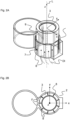
- the equally spaced arrangement of the grooves 8 to each other is evident from the Figure 2B which shows a plan view of the preferred embodiment of the optics carrier 2 with the optical element 3 of the Figure 2A
- a portion of the compressed air DI introduced flows through the grooves 8 on an outer side 9 of the optical element 3 along the longitudinal axis L in the direction of the z-axis.
- the compressed air DI flowing in the grooves 8 causes radially inward directed Compressive forces F, which are shown schematically as black arrows.
- the introduced compressed air DI can move the optical element 3 in the direction of a third degree of freedom, represented as the z-axis, into the operating position of the optical element 3, wherein the operating position can preferably be determined by monitoring a change in a light point of the light emitting unit 4 during the contactless movement of the optical element 3 and the optical element 3 is in the operating position when the light point of the light emitting unit 4 is optimally adjusted.
- the optical element 3 is thus adjusted relative to the light emitting unit 4 and can be attached to the optics carrier 2 in the operating position.
- the z-axis is coaxial with the longitudinal axis L of the optics carrier 2.
- the compressed air DI introduced during fastening in particular during curing of an adhesive, can be regulated in such a way that a distortion caused by the curing of the adhesive is compensated, so that the optical element 3 is adjusted at all times and the light point of the light emitting unit 4 remains optimally adjusted.
- FIG. 1B shows schematically a further preferred embodiment of the adjustment device 1 according to the invention, wherein the same components as in the Figure 1A have the same reference symbols.
- the roles of the light transmitting unit 4 and the light receiving unit 5 are swapped and the optics carrier 2 is now arranged in a fixed position in the defined position relative to the light receiving unit 5.
- the optical element 3 is held for adjustment within the optics carrier 2 in the direction of the first and second degrees of freedom x and y by the introduced compressed air DI and can be moved without contact in the direction of the third degree of freedom z.
- the optical element 3 is movable toward or away from the light receiving unit 5 so that an optimal incidence of a received light on the light receiving unit 5 can be adjusted.
- the compressed air DI can be fed through the electronics card 6 into the optics carrier 2 by means of openings 6a provided in the electronics card 6. This makes it easy to regulate the compressed air DI introduced.
- FIG. 2A a three-dimensional representation of a preferred embodiment of the optics carrier 2 with the optical element 3 of the adjustment device 1 according to the invention is shown, wherein the optics carrier 2 has nine grooves 8 arranged at the same angular distance from one another on the inner wall 7 of the optics carrier 2.
- Figure 3A shows a three-dimensional representation of a further preferred embodiment of the optics carrier 2 with the optical element 3 of the adjustment device 1 according to the invention, wherein in comparison to the embodiment of the Figure 2A a number of grooves 8 provided on the inner wall 7 of the optics carrier 2 is reduced.
- three grooves 8 are provided, arranged at equal distances from each other.
- at least one recess 10 is provided, which - as in the Figure 3C shown - has a larger cross-sectional area A1 than a cross-sectional area A2 of the groove 8.
- the recess 10 has a larger contact surface for the introduced compressed air DI than the groove 8, so that a larger pressure force F results.
- the recess 10 preferably has a defined length I and a defined width b, so that in particular the inwardly open side has a desired size and thus offers a defined area of contact for the compressed air DI on the optical element 3, whereby the pressure force F on the optical element 3 is set to a certain extent via the geometry of the recess 10. As a result, the optical element 3 is exposed to stronger lateral pressure forces F at the position where the recess 10 is provided than in other areas of the groove 8 above or below the recess 10.
- the length I and the width b of the recess 10 can be designed depending on a circumference of the optical element 3.
- the pressure force F on the optical element 3 can be designed as required by adapting the geometry of the recess 10.
- the grooves 8 can be arranged at an unequal angular distance from one another, so that the optical element 3 experiences a resultant force that is different from zero transversely to the longitudinal direction and is therefore not held centrally in relation to the optics carrier 2, but rather strikes a point on the inner wall 7 of the optics carrier 2 at the side.
- the corresponding point on the inner wall 7 of the optics carrier 2 serves as a mechanical stop for the optical element 3 when it is adjusted relative to the light emitting unit 4 or light receiving unit 5.
- the optical element 3 is mounted in the cylindrical optics carrier 2 and the light emitting 4 and light receiving unit 5 on the electronic board 6 of the sensor S. With the adjustment method according to the invention, the optical element 3 - as shown in the Figure 1A shown - relative to the light emitting unit 4 or - as in the Figure 1 B shown - relative to the light receiving unit 5.
- the optics carrier 2 is first placed in a fixed position relative to the light emitting unit 4 or light receiving unit 5.
- the optical element 3 is then introduced into the optics carrier 3.
- compressed air DI is introduced into the optics carrier 2.
- the compressed air DI can be introduced into the optics carrier 2 between the end of the optics carrier 2 facing the electronics card 6 and the electronics card 6 or through the electronics card 6 into the optics carrier 2 by means of openings 6a provided in the electronics card 6.
- the compressed air DI flows into a free space within the optics carrier 2, which is delimited by the optical element 3, the inner wall 7 of the optics carrier 2 and the electronics card 6.
- the optical element 3 is fixed by the compressed air DI in the direction of the first and second degrees of freedom x and y within the optics carrier 2 transversely to the longitudinal axis L of the optics carrier 2.
- the compressed air DI is controlled in such a way that the optical element 3 is moved contactlessly in the direction of the longitudinal axis L into the operating position and is aligned with respect to the light emitting unit 4 or light receiving unit 5.
- the optical element 3 is moved within the optics carrier 2 along the longitudinal axis L of the optics carrier 3 toward the light emitting unit 4 or light receiving unit 5 or away from the light emitting unit 4 or light receiving unit 5.
- an optimal light point of the light emitting unit 4 or an optimal light incidence on the light receiving unit 5 is preferably monitored during the movement of the optical element 3.
- the optical element 3 is fixed in the operating position in which the light point of the light emitting unit 4 or the light incidence on the light receiving unit 5 is optimal, so that the optical element 3 is aligned with respect to the light emitting unit 4 or light receiving unit 5.
- the optical element 3 is preferably attached to the optics carrier 2 in the operating position by means of adhesive, in particular UV light self-curing adhesive.
- the compressed air DI is advantageously switched off after the attachment of the optical element 3 is completed.
Landscapes
- Physics & Mathematics (AREA)
- General Physics & Mathematics (AREA)
- Optics & Photonics (AREA)
- Switches Operated By Changes In Physical Conditions (AREA)
- Geophysics And Detection Of Objects (AREA)
- Moving Of The Head For Recording And Reproducing By Optical Means (AREA)
Abstract
Description
- Die Erfindung betrifft eine Justage-Vorrichtung zum Justieren eines optischen Elements zu einer Lichtsende- oder Lichtempfangseinheit eines optoelektronischen Sensors gemäß dem Anspruch 1 und ein Justage-Verfahren gemäß dem Anspruch 9.
- Ein optoelektronischer Sensor, wie beispielsweise ein Codelesegerät, wird in vielen Bereichen des Alltags eingesetzt, um Informationsdaten aus einem Bildobjekt auszulesen, wobei das Bildobjekt in Form eines eindimensionalen oder zweidimensionalen Strichcodes ausgebildet sein kann. Hierzu weist der optoelektronische Sensor eine Lichtsende- und Lichtempfangseinheit auf, die auf einer Elektronikkarte angeordnet ist. Die Lichtsendeeinheit dient zum Beleuchten eines Lesebereichs des Sensors, um insbesondere das Bildobjekt zu belichten, und die Lichtempfangseinheit dient zum Empfangen von von dem Bildobjekt remittierten Licht, um aus dem empfangenen Licht Signale zum Ermitteln der Informationsdaten des Bildobjekts zu erzeugen.
- Zur Verbesserung der Sende- bzw. Empfangsleistung wird der Lichtsende- und/oder Lichtempfangseinheit ein optisches Element, vorzugsweise in Form einer Linse, zugeordnet, das in einem Optikträger gelagert und mit dem Optikträger befestigt ist, insbesondere verklebt oder verschraubt. Hierzu wird der Optikträger mit dem optischen Element ortsfest in einer definierten Position relativ zu der Lichtsende- bzw. Lichtempfangseinheit angeordnet. Eine Genauigkeit der Positionierung des optischen Elements in dem Optikträger in Bezug zu der Lichtsende- bzw. Lichtempfangseinheit spielt hierbei eine zentrale Rolle für die Leistungsfähigkeit des Sensors.
- Hierzu muss das optische Element in Bezug zu der Lichtsende- bzw. Lichtempfangseinheit justiert werden. Bei einer Justage wird anhand eines Optimums für einen geeigneten Messparameter, wie beispielsweise eine Schärfe eines Laserspots oder eines Empfangssignalpegels, eine optimale Betriebsposition des optischen Elements innerhalb des Optikträgers gegenüber der Lichtsende- bzw. Lichtempfangseinheit ermittelt und das zu justierende optische Element in dieser Betriebsposition positioniert und befestigt. Das Befestigen erfolgt vorzugsweise durch UV-Licht selbsthärtenden Kleber.
- Eine justierte Fixierung des optischen Elements in drei Dimensionen stellt, zum Beispiel aufgrund eines Verzugs des Klebstoffs beim Aushärten, ein aufwändig zu lösendes Problem dar. Um das Problem zu lösen, können Freiheitsgrade des optischen Elements bei der Justage reduziert oder die Justage auf verschiedene Komponenten aufgeteilt werden.
- Zu einer Reduzierung der Freiheitsgrade wird beispielsweise das optische Element mittels eines Greifers in einer Ebene fixiert und in Richtung eines zu der Ebene senkrecht stehenden Freiheitsgrads mittels einer hochgenauen Verfahrachse in die Betriebsposition verfahren. Es kann durch das Greifen des Greifers jedoch bereits eine mechanische Überbestimmung vorliegen, so dass ein spielfreies Halten nicht gewährleistet ist. Eine stabile, völlig kräftefreie Fixierung des zu justierenden optischen Elements ist nur schwer oder gar nicht zu realisieren.
- Eine Aufteilung der Freiheitsgrade auf verschiedene Komponenten ist aufwändig und eine gewisse Toleranz unvermeidbar, so dass sich eine Ungenauigkeit der Justage des optischen Elements ergeben kann.
- Es ist daher eine Aufgabe der Erfindung, eine Justage-Vorrichtung zum Justieren eines optischen Elements relativ zu einer Lichtsende- oder Lichtempfangseinheit eines optoelektronischen Sensors bereitzustellen, die eine einfache und präzise Justage des optischen Elements gewährleistet.
- Die Aufgabe wird erfindungsgemäß durch eine Justage-Vorrichtung mit den Merkmalen des Anspruchs 1 gelöst.
- Hierbei ist die Justage-Vorrichtung zum Justieren eines optischen Elements relativ zu einer Lichtsende- oder Lichtempfangseinheit eines optoelektronischen Sensors, wobei das optische Element in einem zylindrischen Optikträger gelagert ist und die Lichtsende- bzw. Lichtempfangseinheit auf einer Elektronikkarte des Sensors angeordnet ist, derart ausgebildet, dass der Optikträger ortsfest in einer definierten Position relativ zu der Lichtsende- bzw. Lichtempfangseinheit anordenbar ist, und dass Druckluft in den Optikträger einleitbar ist, um das in dem Optikträger vorgesehene optische Element in Richtung eines ersten und eines zweiten Freiheitsgrads innerhalb des Optikträgers quer zu einer Längsachse zu fixieren und um das optische Element in Richtung der Längsachse in eine definierte Betriebsposition berührungslos bewegen zu können, wobei das optische Element entlang der Längsachse des Optikträgers zu der Lichtsende- bzw. Lichtempfangseinheit hin oder von der Lichtsende- bzw. Lichtempfangseinheit weg bewegbar ist, so dass das optische Element gegenüber der Lichtsende- bzw. Lichtempfangseinheit in die definierte Betriebsposition ausrichtbar und in der Betriebsposition befestigbar ist, in der das optische Element gegenüber der Lichtsende- bzw. Lichtempfangseinheit justiert ist.
- Hieraus ergibt sich der technische Vorteil, dass das optische Element ohne eine mechanische Überbestimmung durch die Justage-Vorrichtung in Richtung von zwei Freiheitsgraden stabil und spielfrei fixiert ist, bei gleichzeitiger Bewegbarkeit in Richtung eines zu den beiden anderen Freiheitsgraden senkrechten dritten Freiheitsgrads. Hierbei umfasst das optische Element vorzugsweise eine Linse.
- Durch das berührungslose Bewegen des optischen Elements kann somit vorteilhafterweise sowohl die Kollimation der Lichtsende- bzw. Lichtempfangseinheit als auch die Winkelausrichtung gleichzeitig ausgeführt werden. Ein entsprechendes Regeln der zugeführten Druckluft ist auszuführen.
- Gemäß einem bevorzugten Ausführungsbeispiel sind an einer Innenwand des Optikträgers zumindest zwei Nuten vorgesehen, die sich parallel zu der Längsachse des Optikträgers erstrecken und zum Leiten der Druckluft ausgebildet sind. Vorteilhafterweise sind die Nuten an der Innenwand in gleichen oder ungleichen Abständen, insbesondere Winkelabständen, zueinander angeordnet. Damit ist ein vielfältiger Einsatz der Justage-Vorrichtung möglich, da die Nuten bei der Herstellung des Optikträgers eingeplant und vorgesehen werden können, so dass unterschiedliche Sensortypen, insbesondere mit unterschiedlichen optischen Elementen, mit der Justage-Vorrichtung justiert werden können.
- Bei einer Anordnung der Nuten in gleichen Abständen zueinander ergibt sich der Vorteil, dass das optische Element im Innern des Optikträgers einfach zentriert werden kann, wobei vorausgesetzt wird, dass die offenen Seiten der Nuten gleich große Dimensionen haben, so dass der in den Nuten herrschende Luftdruck je Nut gleich große Kräfte auf das optische Element ausübt. Wenn die Nuten wiederum in ungleichen Abständen zueinander an der Innenwand des Optikträgers vorgesehen sind, kann auf das optische Element durch den Luftdruck eine gezielte seitliche Kraft ausgeübt werden, um eine Stelle der Innenwand des Optikträgers als Anschlag für das optische Element an den Optikträger bei der Justage zu nutzen. Ein Verzug der Position des optischen Elements kann durch einen solchen Anschlag reduziert werden.
- Ferner ist gemäß einem weiteren bevorzugten Ausführungsbeispiel entlang einer Nut zumindest eine Ausnehmung vorgesehen, die eine größere Querschnittfläche und damit größere Angriffsfläche für den Luftdruck als die Nut aufweist. Daraus ergibt sich der Vorteil, dass sich im Bereich der Ausnehmung aufgrund der größeren Angriffsfläche eine größere Druckkraft auf eine Außenfläche des optischen Elements als entlang der Nut ergibt. Dadurch kann eine stärkere Fixierung des optischen Elements an der Stelle der Ausnehmung erzielt werden. Vorteilhafterweise weist die Ausnehmung eine definierte Länge und eine definierte Breite auf, so dass eine vordefinierte Größe der Druckkraft an der Stelle der Ausnehmung einfach geplant und ausgebildet werden kann. Insbesondere sind die definierte Länge und Breite der Ausnehmung in Abhängigkeit zu einem Umfang des optischen Elements auslegbar.
- Gemäß einem weiteren bevorzugten Ausführungsbeispiel ist die Justage-Vorrichtung derart ausgebildet, dass die Druckluft zwischen einem der Elektronikkarte zugewandten Ende des Optikträgers und der Elektronikkarte in den Optikträger zuführbar ist, oder die Druckluft ist mittels in der Elektronikkarte vorgesehenen Öffnungen durch die Elektronikkarte in den Optikträger zuführbar.
- Es ist ferner eine Aufgabe der vorliegenden Erfindung, ein Justage-Verfahren zum Justieren eines optischen Elements relativ zu einer Lichtsende- oder Lichtempfangseinheit eines optoelektronischen Sensors bereitzustellen, mit dem eine präzise und spielfreie Justage des optischen Elements einfach ausgeführt werden kann.
- Die Aufgabe wird erfindungsgemäß durch ein Verfahren mit den Merkmalen des Anspruchs 9 gelöst.
- Hierbei umfasst das Justage-Verfahren, wobei das optische Element in einem zylindrischen Optikträger gelagert ist und die Lichtsende- bzw. Lichtempfangseinheit auf einer Elektronikkarte des Sensors angeordnet ist, die Schritte:
- Platzieren des Optikträgers ortsfest in einer definierten Position relativ zu der Lichtsende- bzw. Lichtempfangseinheit,
- Einführen des optischen Elements in den Optikträger,
- Zuführen von Druckluft in den Optikträger, um das optische Element in Richtung eines ersten und eines zweiten Freiheitsgrads innerhalb des Optikträgers quer zu einer Längsachse des Optikträgers zu fixieren,
- Regeln der zugeführten Druckluft, um das optische Element berührungslos in Richtung der Längsachse in einer definierten Betriebsposition zu bewegen und gegenüber der Lichtsende- bzw. Lichtempfangseinheit auszurichten, und
- Befestigen des optischen Elements in der Betriebsposition, in der das optische Element gegenüber der Lichtsende- bzw. Lichtempfangseinheit justiert ist.
- Hierdurch ergibt sich der technische Vorteil, dass das optische Element entlang der Längsachse des Optikträgers bei gleichzeitiger Fixierung quer dazu in Richtung der anderen relevanten Freiheitsgrade justierbar ist.
- Vorzugsweise wird das optische Element innerhalb des Optikträgers entlang der Längsachse des Optikträgers zu der Lichtsende- bzw. Lichtempfangseinheit hin oder von der Lichtsende- bzw. Lichtempfangseinheit wegbewegt.
- Insbesondere wird das optische Element mittels Klebstoff an dem Optikträger in der Betriebsposition befestigt. Vorteilhafterweise wird die Druckluft abgeschaltet, nachdem das Befestigen des optischen Elements vollendet ist. Mit anderen Worten, die Druckluft wird so lange zugeführt, bis zum Beispiel der Klebstoff vollständig ausgehärtet ist.
- Ferner wird vorzugsweise die Druckluft entsprechend einer Abweichung der Position des optischen Elements von der definierten Betriebsposition nachgeregelt, wenn beim Befestigen des optischen Elements die Abweichung erfasst wird. Hierdurch kann durch die Nachregelung der zugeführten Druckluft die Fixierung des optischen Elements in Abhängigkeit einer Aushärtung des Klebstoffs eingestellt werden. Zusätzlich wird einem Verzug durch den Klebstoff entgegengewirkt.
- Die Erfindung wird nachstehend auch hinsichtlich weiterer Merkmale und Vorteile beispielhaft anhand von Ausführungsformen und unter Bezug auf die beigefügte Zeichnung näher erläutert. Die Abbildungen der Zeichnung zeigen in:
- Fig. 1A
- eine schematische Darstellung eines bevorzugten Ausführungsbeispiels einer erfindungsgemäßen Justage-Vorrichtung mit Hauptkomponenten eines optoelektronischen Sensors,
- Fig. 1B
- eine schematische Darstellung eines weiteren bevorzugten Ausführungsbeispiels der erfindungsgemäßen Justage-Vorrichtung,
- Fig. 2A
- eine dreidimensionale Darstellung eines bevorzugten Ausführungsbeispiels eines Optikträgers mit einem optischen Element der erfindungsgemäßen Justage-Vorrichtung,
- Fig. 2B
- eine Draufsicht auf das bevorzugte Ausführungsbeispiel des Optikträgers der
Figur 2A , - Fig. 3A
- eine dreidimensionale Darstellung eines weiteren bevorzugten Ausführungsbeispiels eines Optikträgers mit einem optischen Element der erfindungsgemäßen Justage-Vorrichtung,
- Fig. 3B
- eine Draufsicht auf das bevorzugte Ausführungsbeispiel des Optikträgers der
Figur 3A , und - Fig. 3C
- einen Ausschnitt einer Detailschnittansicht des bevorzugten Ausführungsbeispiels des Optikträgers der
Figur 3A . -
Figur 1A zeigt eine schematische Darstellung eines bevorzugten Ausführungsbeispiels einer erfindungsgemäßen Justage-Vorrichtung 1, bei der ein zylindrischer Optikträger 2 ortsfest in einer definierten Position relativ zu einer Lichtsendeeinheit 4 eines optoelektronischen Sensors S angeordnet ist. Die Lichtsendeeinheit 4 des Sensors S ist neben einer zugehörigen Lichtempfangseinheit 5 positioniert, wobei die Lichtsende- 4 bzw. Lichtempfangseinheit 5 auf einer Elektronikkarte 6 des Sensors S angeordnet ist. - In dem zylindrischen Optikträger 2 ist ein optisches Element 3 gelagert, das vorzugsweise eine optische Linse umfasst, wobei mittels der erfindungsgemäßen Justage-Vorrichtung 1 das optische Element 3 relativ zu der Lichtsendeeinheit 4 justierbar ist.
- Hierbei ist die Justage-Vorrichtung 1 derart ausgebildet, dass Druckluft DI - wie durch die gestrichelten Pfeile dargestellt - in den Optikträger 2 einleitbar ist. Die Druckluft DI ist insbesondere zwischen einem der Elektronikkarte 6 zugewandten Ende des Optikträgers 2 und der Elektronikkarte 6 in den Optikträger 2 zuführbar, wobei die Druckluft DI durch nicht dargestellte Druckluftleitungen geleitet ist.
- Hierdurch ist ein berührungsloses Bewegen des in dem Optikträger 2 vorgesehenen optischen Elements 3 entlang einer Längsachse L des Optikträgers 2 - gemäß dem dargestellten Doppelpfeil - möglich, denn bei aufrechtstehendem Optikträger 2 wirkt auf das optische Element 3 einerseits die Schwerkraft und andererseits eine dem entgegengerichtete Druckkraft, die durch den Luftdruck erzeugt ist. Durch die Justierung und Balance dieser beiden Kräfte kann das optische Element 3 in die gewünschte Betriebsposition entlang der Längsachse L gebracht und gehalten werden. In dieser Betriebsposition, in der das optische Element 3 gegenüber der Lichtsendeeinheit 4 justiert ist, kann es festgemacht werden, beispielsweise durch Kleben.
- Da das optische Element 3 in den Optikträger 2 nicht eingepresst ist, kann es sich, bevor es verklebt wird, noch in Richtung eines ersten Freiheitsgrads x und eines zweiten Freiheitsgrads y innerhalb des Optikträgers 2 quer zu der Längsachse L zu einem gewissen Grade bewegen. Der erste Freiheitsgrad x ist als x-Achse dargestellt, die senkrecht zu der
Figur 1 steht und aus der Blattebene herauszeigt. Der zweite Freiheitsgrad y ist als y-Achse dargestellt, die parallel zu der Elektronikkarte 6 verläuft und in der Blattebene liegt. - Die Druckluft DI wird nun auch dazu genutzt, das optische Element 3 quer zur Längsrichtung L zu halten. Dazu weist der Optikträger 2 an einer Innenwand 7 eine Mehrzahl an Nuten 8 auf, die sich parallel zu der Längsachse L des Optikträgers 2 erstrecken und durch die die eingeleitete Druckluft DI geführt ist. Zwar wird auch ein kleiner Teil der Druckluft DI durch den Zwischenraum zwischen optischem Element 3 und Optikträger 2 treten, dieser Teil soll allerdings vernachlässigbar gegenüber dem Anteil der Druckluft DI sein, der durch die Nuten 8 strömt. Durch den Druck der Luft in den Nuten 8 wirken an jeder offenen Seite einer Nut 8 seitliche Druckkräfte F auf das optische Element 3.
- Im ersten Ausführungsbeispiel sind die Nuten 8 vorzugsweise in einem gleichen Winkelabstand voneinander angeordnet und haben gleiche Dimensionen, also gleich dimensionierte offene Seiten. Die gleich beabstandete Anordnung der Nuten 8 zueinander ist aus der
Figur 2B ersichtlich, die eine Draufsicht auf das bevorzugte Ausführungsbeispiel des Optikträgers 2 mit dem optischen Element 3 derFigur 2A darstellt. Durch die Nuten 8 strömt ein Teil der eingeleiteten Druckluft DI an einer Außenseite 9 des optischen Elements 3 entlang der Längsachse L in Richtung der z-Achse. Die in den Nuten 8 strömende Druckluft DI bewirkt radial nach innen gerichtete Druckkräfte F, die schematisch als schwarze Pfeile dargestellt sind. Diese Druckkräfte F halten das optische Element 3 mittig im Optikträger 2, so dass das optische Element 3 in Richtung des ersten und des zweiten Freiheitsgrads x und y bzw. in Richtung der x- und y-Achse quer zu dem dritten Freiheitsgrad z bzw. der z-Achse fixiert ist. Das optische Element 3 ist innerhalb des Optikträgers 2 dann noch entlang der Längsachse des Optikträgers 2 in Richtung des dritten Freiheitgrads z wie oben beschrieben bewegbar, so dass die Justage des optischen Elements 3 stabil und präzise ohne mechanische Überbestimmung durchgeführt werden kann. - Die eingeleitete Druckluft DI kann, wie oben beschrieben, das optische Element 3 in Richtung eines als z-Achse dargestellten, dritten Freiheitsgrads in die Betriebsposition des optischen Elements 3 bewegen, wobei die Betriebsposition vorzugsweise dadurch bestimmbar ist, dass eine Änderung eines Lichtpunkts der Lichtsendeeinheit 4 während dem berührungslosen Bewegen des optischen Elements 3 überwacht wird und das optische Element 3 sich in der Betriebsposition befindet, wenn der Lichtpunkt der Lichtsendeeinheit 4 optimal eingestellt ist. Damit ist das optische Element 3 gegenüber der Lichtsendeeinheit 4 justiert und kann in der Betriebsposition an dem Optikträger 2 befestigt werden. Die z-Achse ist koaxial zu der Längsachse L des Optikträgers 2.
- Vorteilhafterweise ist die eingeleitete Druckluft DI während des Befestigens, insbesondere eines Aushärtens eines Klebers, derart regelbar, dass ein Verzug durch das Aushärten des Klebers ausgeglichen wird, so dass das optische Element 3 zu jedem Zeitpunkt justiert und der Lichtpunkt der Lichtsendeeinheit 4 optimal eingestellt bleibt.
- Die
Figur 1B zeigt schematisch ein weiteres bevorzugtes Ausführungsbeispiel der erfindungsgemäßen Justage-Vorrichtung 1, wobei gleiche Komponenten wie in derFigur 1A die gleichen Bezugszeichen aufweisen. - In diesem Ausführungsbeispiel sind die Rollen von Lichtsendeeinheit 4 und Lichtempfangseinheit 5 vertauscht und der Optikträger 2 ist ortsfest in der definierten Position jetzt relativ zu der Lichtempfangseinheit 5 angeordnet. Wie zuvor ist mittels der eingeleiteten Druckluft DI das optische Element 3 zur Justage innerhalb des Optikträgers 2 in Richtung des ersten und des zweiten Freiheitsgrads x und y gehalten und berührungslos in Richtung des dritten Freiheitsgrads z bewegbar.
- Das heißt, das optische Element 3 ist zu der Lichtempfangseinheit 5 hin oder von der Lichtempfangseinheit 5 weg bewegbar, so dass ein optimaler Lichteinfall eines empfangenen Lichts auf die Lichtempfangseinheit 5 eingestellt werden kann.
- Vorteilhafterweise ist bei diesem Ausführungsbeispiel die Druckluft DI mittels in der Elektronikkarte 6 vorgesehenen Öffnungen 6a durch die Elektronikkarte 6 in den Optikträger 2 zuführbar. Hierdurch kann eine Regelung der eingeleiteten Druckluft DI einfach ausgeführt werden.
- In der
Figur 2A ist eine dreidimensionale Darstellung eines bevorzugten Ausführungsbeispiels des Optikträgers 2 mit dem optischen Element 3 der erfindungsgemäßen Justage-Vorrichtung 1 gezeigt, wobei der Optikträger 2 neun in gleichem Winkelabstand zueinander angeordneten Nuten 8 an der Innenwand 7 des Optikträgers 2 aufweist. -
Figur 3A zeigt eine dreidimensionale Darstellung eines weiteren bevorzugten Ausführungsbeispiels des Optikträgers 2 mit dem optischen Element 3 der erfindungsgemäßen Justage-Vorrichtung 1, wobei im Vergleich zu dem Ausführungsbeispiel derFigur 2A eine Anzahl der an der Innenwand 7 des Optikträgers 2 vorgesehenen Nuten 8 reduziert ist. - Bei dem Ausführungsbeispiel sind drei zueinander gleich beabstandet angeordnete Nuten 8 vorgesehen. Entlang jeder Nut 8 ist zumindest eine Ausnehmung 10 vorgesehen, die - wie in der
Figur 3C dargestellt - eine größere Querschnittfläche A1 als eine Querschnittfläche A2 der Nut 8 aufweist. Dadurch hat die Ausnehmung 10 eine größere Angriffsfläche für die eingeleitete Druckluft DI als die Nut 8, so dass sich eine größere Druckkraft F ergibt. - Hierbei weist die Ausnehmung 10 vorzugsweise eine definierte Länge I und eine definierte Breite b auf, so dass insbesondere die nach innen offene Seite eine gewünschte Größe hat und damit eine definierte Angriffsfläche der Druckluft DI an das optische Element 3 bietet, womit zu einem gewissen Grad die Druckkraft F an das optische Element 3 über die Geometrie der Ausnehmung 10 eingestellt ist. Dadurch ist das optische Element 3 an der Position, wo die Ausnehmung 10 vorgesehen ist, stärkeren seitlichen Druckkräften F ausgesetzt als in anderen Bereichen der Nut 8 ober- oder unterhalb der Ausnehmung 10.
- Insbesondere sind die Länge I und die Breite b der Ausnehmung 10 in Abhängigkeit zu einem Umfang des optischen Elements 3 auslegbar. Hierdurch kann je nach Bedarf die Druckkraft F auf das optische Element 3 durch Anpassung der Geometrie der Ausnehmung 10 ausgelegt werden.
- In den
Figuren 2A, 2B ,3A und 3B ist eine Anordnung der Nuten 8 dargestellt, bei der die Nuten 8 gleichverteilt über den Umfang sind, also in einem gleichen Winkelabstand zueinander an der Innenwand 7 des Optikträgers 2 angeordnet sind. - Gemäß einem nicht dargestellten Ausführungsbeispiel der Justage-Vorrichtung 1 können die Nuten 8 in einem ungleichen Winkelabstand zueinander angeordnet sein, so dass das optische Element 3 quer zur Längsrichtung eine von Null verschiedene resultierende Kraft erfährt und damit nicht mittig in Bezug zu dem Optikträger 2 gehalten ist, sondern zur Seite hin an eine Stelle der Innenwand 7 des Optikträgers 2 anschlägt. Das heißt, die entsprechende Stelle an der Innenwand 7 des Optikträgers 2 dient als mechanischer Anschlag für das optische Element 3 bei dessen Justage gegenüber der Lichtsende- 4 bzw. Lichtempfangseinheit 5.
- Nachfolgend wird das erfindungsgemäße Justage-Verfahren zum Justieren des optischen Elements 3 zu der Lichtsende- 4 oder Lichtempfangseinheit 5 des optoelektronischen Sensors S beschrieben.
- Wie bereits erwähnt, ist das optische Element 3 in dem zylindrischen Optikträger 2 gelagert und die Lichtsende- 4 und Lichtempfangseinheit 5 auf der Elektronikkarte 6 des Sensors S angeordnet. Mit dem erfindungsgemäßen Justage-Verfahren kann das optische Element 3 - wie in der
Figur 1A dargestellt - relativ zu der Lichtsendeeinheit 4 oder - wie in derFigur 1 B dargestellt - relativ zu der Lichtempfangseinheit 5 justiert werden. - Bei dem Justage-Verfahren wird zuerst der Optikträger 2 ortsfest in einer definierten Position relativ zu der Lichtsende- 4 bzw. Lichtempfangseinheit 5 platziert. Das optische Element 3 wird dann in den Optikträger 3 eingeführt.
- Wenn das optische Element 3 in den Optikträger 2 eingeführt ist, wird Druckluft DI in den Optikträger 2 eingeleitet. Hierbei kann die Druckluft DI zwischen dem der Elektronikkarte 6 zugewandten Ende des Optikträgers 2 und der Elektronikkarte 6 oder mittels in der Elektronikkarte 6 vorgesehenen Öffnungen 6a durch die Elektronikkarte 6 in den Optikträger 2 eingeleitet werden. Die Druckluft DI strömt in einen Freiraum innerhalb des Optikträgers 2, der von dem optischen Element 3, der Innenwand 7 des Optikträgers 2 und der Elektronikkarte 6 begrenzt ist.
- Das optische Element 3 wird durch die Druckluft DI in Richtung des ersten und des zweiten Freiheitsgrads x und y innerhalb des Optikträgers 2 quer zu der Längsachse L des Optikträgers 2 fixiert.
- Die Druckluft DI wird derart geregelt, dass das optische Element 3 berührungslos in Richtung der Längsachse L in die Betriebsposition bewegt und gegenüber der Lichtsende- 4 bzw. Lichtempfangseinheit 5 ausgerichtet wird. Insbesondere wird das optische Element 3 innerhalb des Optikträgers 2 entlang der Längsachse L des Optikträgers 3 zu der Lichtsende- 4 bzw. Lichtempfangseinheit 5 hin oder von der Lichtsende- 4 bzw. Lichtempfangseinheit 5 weg bewegt. Hierbei wird vorzugsweise während dem Bewegen des optischen Elements 3 auf einen optimalen Lichtpunkt der Lichtsendeeinheit 4 bzw. auf einen optimalen Lichteinfall auf die Lichtempfangseinheit 5 überwacht.
- Das optische Element 3 wird in der Betriebsposition befestigt, in welcher der Lichtpunkt der Lichtsendeeinheit 4 bzw. der Lichteinfall auf die Lichtempfangseinheit 5 optimal ist, so dass das optische Element 3 gegenüber der Lichtsende- 4 bzw. Lichtempfangseinheit 5 justiert ist. Vorzugsweise wird das optische Element 3 mittels Klebstoff, insbesondere UV-Licht selbsthärtenden Klebstoff, an dem Optikträger 2 in der Betriebsposition befestigt. Die Druckluft DI wird vorteilhafterweise dann abgeschaltet, nachdem das Befestigen des optischen Elements 3 vollendet ist.
- Zusätzlich wird während des Aushärtens des Klebstoffs auf eine Änderung des Lichtpunkts der Lichtsendeeinheit 4 bzw. des Lichteinfalls auf die Lichtempfangseinheit 5 überwacht und durch gezielte Regelung der Druckluft DI der Änderung entgegengewirkt, so dass ein Verzug verhindert wird und das optische Element 3 gegenüber der Lichtsendeeinheit 4 bzw. der Lichtempfangseinheit 5 zu jedem Zeitpunkt justiert bleibt.
-
- 1
- Justage-Vorrichtung
- 2
- Optikträger
- 3
- optisches Element
- 4
- Lichtsendeeinheit
- 5
- Lichtempfangseinheit
- 6
- Elektronikkarte
- 6a
- Öffnungen
- 7
- Innenwand des Optikträgers
- 8
- Nut
- 9
- Außenseite des optischen Elements
- 10
- Ausnehmung
- A1
- Querschnittfläche der Ausnehmung
- A2
- Querschnittfläche der Nut
- b
- Breite der Ausnehmung
- DI
- Druckluft
- F
- Druckkraft
- I
- Länge der Ausnehmung
- L
- Längsachse
- x
- erster Freiheitsgrad
- y
- zweiter Freiheitsgrad
- z
- dritter Freiheitsgrad
Claims (12)
- Justage-Vorrichtung (1) zum Justieren eines optischen Elements (3) relativ zu einer Lichtsende- (4) oder Lichtempfangseinheit (5) eines optoelektronischen Sensors (S), wobei das optische Element (3) in einem zylindrischen Optikträger (2) gelagert ist und die Lichtsende- (4) bzw. Lichtempfangseinheit (5) auf einer Elektronikkarte (6) des Sensors (S) angeordnet ist, undwobei die Justage-Vorrichtung (1) derart ausgebildet ist, dass der Optikträger (2) ortsfest in einer definierten Position relativ zu der Lichtsende- (4) bzw. Lichtempfangseinheit (5) anordenbar ist, unddass Druckluft (DI) in den Optikträger (2) einleitbar ist, um das in dem Optikträger (2) vorgesehene optische Element (3) in Richtung eines ersten und eines zweiten Freiheitsgrads (x und y) innerhalb des Optikträgers (2) quer zu einer Längsachse (L) zu fixieren und um das optische Element (3) in Richtung der Längsachse (L) in eine definierte Betriebsposition berührungslos zu bewegen,wobei das optische Element (3) entlang der Längsachse (L) des Optikträgers (2) zu der Lichtsende- (4) bzw. Lichtempfangseinheit (5) hin oder von der Lichtsende- (4) bzw. Lichtempfangseinheit (5) weg bewegbar ist, so dass das optische Element (3) gegenüber der Lichtsende- (4) bzw. Lichtempfangseinheit (5) in die definierte Betriebsposition ausrichtbar und in der Betriebsposition befestigbar ist, in der das optische Element (3) gegenüber der Lichtsende- (4) bzw. Lichtempfangseinheit (5) justiert ist.
- Justage-Vorrichtung (1) nach Anspruch 1, wobei das optische Element (3) eine Linse umfasst.
- Justage-Vorrichtung (1) nach Anspruch 1 oder 2, wobei an einer Innenwand (7) des Optikträgers (2) zumindest zwei Nuten (8) vorgesehen sind, die sich parallel zu der Längsachse (L) des Optikträgers (2) erstrecken und zum Leiten der Druckluft (DI) ausgebildet sind.
- Justage-Vorrichtung (1) nach Anspruch 3, wobei die Nuten (8) an der Innenwand (7) in gleichen oder ungleichen Abständen zueinander angeordnet sind.
- Justage-Vorrichtung (1) nach Anspruch 3 oder 4, wobei entlang einer Nut (8) zumindest eine Ausnehmung (10) vorgesehen ist, die eine größere Querschnittfläche (A1) als eine Querschnittfläche (A2) der Nut (8) aufweist.
- Justage-Vorrichtung (1) nach Anspruch 5, wobei die Ausnehmung (10) eine definierte Länge (I) und eine definierte Breite (b) aufweist.
- Justage-Vorrichtung (1) nach Anspruch 6, wobei die definierte Länge (I) und Breite (b) der Ausnehmung (10) in Abhängigkeit zu einem Umfang des optischen Elements (3) auslegbar sind.
- Justage-Vorrichtung (1) nach einem der vorhergehenden Ansprüche 1 bis 7, wobei die Justage-Vorrichtung (1) derart ausgebildet ist, dass die Druckluft (DI) zwischen einem der Elektronikkarte (6) zugewandten Ende des Optikträgers (2) und der Elektronikkarte (6) in den Optikträger (2) zuführbar ist oder die Druckluft (DI) mittels in der Elektronikkarte (6) vorgesehenen Öffnungen (6a) durch die Elektronikkarte (6) in den Optikträger (2) zuführbar ist.
- Justage-Verfahren zum Justieren eines optischen Elements (3) relativ zu einer Lichtsende- (4) oder Lichtempfangseinheit (5) eines optoelektronischen Sensors (S), wobei das optische Element (3) in einem zylindrischen Optikträger (2) gelagert ist und die Lichtsende- (4) bzw. Lichtempfangseinheit (5) auf einer Elektronikkarte (6) des Sensors (S) angeordnet ist, umfassend die Schritte:Platzieren des Optikträgers (2) ortsfest in einer definierten Position relativ zu der Lichtsende- (4) bzw. Lichtempfangseinheit (5),Einführen des optischen Elements (3) in den Optikträger (2),Zuführen von Druckluft (DI) in den Optikträger (3), um das optische Element (3) in Richtung eines ersten und eines zweiten Freiheitsgrads (x und y) innerhalb des Optikträgers (2) quer zu einer Längsachse (L) des Optikträgers (2) zu fixieren,Regeln der zugeführten Druckluft (DI), um das optische Element (3) berührungslos in Richtung der Längsachse (L) in eine definierte Betriebsposition zu bewegen und gegenüber der Lichtsende- (4) bzw. Lichtempfangseinheit (5) auszurichten, undBefestigen des optischen Elements (3) in der Betriebsposition, in der das optische Element (3) gegenüber der Lichtsende- (4) bzw. Lichtempfangseinheit (5) justiert ist.
- Justage-Verfahren nach Anspruch 9, wobei das optische Element (3) mittels Klebstoff an dem Optikträger (2) in der Betriebsposition befestigt wird.
- Justage-Verfahren nach Anspruch 9 oder 10, wobei die Druckluft (DI) abgeschaltet wird, nachdem das Befestigen des optischen Elements (3) vollendet ist.
- Justage-Verfahren nach einem der vorhergehenden Ansprüche 9 bis 11, wobei die Druckluft (DI) entsprechend einer Abweichung der Position des optischen Elements von der definierten Betriebsposition nachgeregelt wird, wenn beim Befestigen des optischen Elements (3) die Abweichung erfasst wird.
Applications Claiming Priority (1)
| Application Number | Priority Date | Filing Date | Title |
|---|---|---|---|
| DE102022134544.0A DE102022134544B3 (de) | 2022-12-22 | 2022-12-22 | Justage-Vorrichtung und Justage-Verfahren |
Publications (2)
| Publication Number | Publication Date |
|---|---|
| EP4390491A1 true EP4390491A1 (de) | 2024-06-26 |
| EP4390491B1 EP4390491B1 (de) | 2025-01-29 |
Family
ID=88306916
Family Applications (1)
| Application Number | Title | Priority Date | Filing Date |
|---|---|---|---|
| EP23208652.0A Active EP4390491B1 (de) | 2022-12-22 | 2023-11-08 | Justage-vorrichtung und justage-verfahren |
Country Status (2)
| Country | Link |
|---|---|
| EP (1) | EP4390491B1 (de) |
| DE (1) | DE102022134544B3 (de) |
Citations (3)
| Publication number | Priority date | Publication date | Assignee | Title |
|---|---|---|---|---|
| DE102005046154A1 (de) * | 2005-09-27 | 2007-03-29 | Siemens Ag | Messvorrichtung und Messsystem zum Inspizieren einer Oberfläche eines Substrates |
| DE102007047109A1 (de) * | 2007-10-01 | 2009-04-09 | Carl Zeiss Smt Ag | Optisches System, insbesondere Projektionsobjektiv der Mikrolithographie |
| EP2370189B1 (de) * | 2008-11-14 | 2013-08-28 | Fraunhofer-Gesellschaft zur Förderung der angewandten Forschung e.V. | Transport eines objekts über eine oberfläche |
Family Cites Families (3)
| Publication number | Priority date | Publication date | Assignee | Title |
|---|---|---|---|---|
| NL161265C (nl) | 1974-02-15 | 1980-01-15 | Philips Nv | Werkwijze voor het centreren van een lens in een vatting. |
| DE3930629A1 (de) | 1989-09-13 | 1991-03-14 | Siemens Ag | Vorrichtung zum parallelen ausrichten der auflageflaechen zweier bauteile und verfahren zum betrieb der vorrichtung |
| DE102009024870A1 (de) | 2008-06-10 | 2009-12-31 | Carl Zeiss Smt Ag | Optische Einrichtung mit einstellbarer Kraftwirkung auf ein optisches Modul |
-
2022
- 2022-12-22 DE DE102022134544.0A patent/DE102022134544B3/de active Active
-
2023
- 2023-11-08 EP EP23208652.0A patent/EP4390491B1/de active Active
Patent Citations (3)
| Publication number | Priority date | Publication date | Assignee | Title |
|---|---|---|---|---|
| DE102005046154A1 (de) * | 2005-09-27 | 2007-03-29 | Siemens Ag | Messvorrichtung und Messsystem zum Inspizieren einer Oberfläche eines Substrates |
| DE102007047109A1 (de) * | 2007-10-01 | 2009-04-09 | Carl Zeiss Smt Ag | Optisches System, insbesondere Projektionsobjektiv der Mikrolithographie |
| EP2370189B1 (de) * | 2008-11-14 | 2013-08-28 | Fraunhofer-Gesellschaft zur Förderung der angewandten Forschung e.V. | Transport eines objekts über eine oberfläche |
Also Published As
| Publication number | Publication date |
|---|---|
| DE102022134544B3 (de) | 2023-11-02 |
| EP4390491B1 (de) | 2025-01-29 |
Similar Documents
| Publication | Publication Date | Title |
|---|---|---|
| DE69420915T2 (de) | Kopplungsstruktur zwischen optischem Halbleiter und optischem Wellenleiter, und Kopplungsverfahren | |
| EP2093537B1 (de) | Verfahren und Vorrichtung zur Ermittlung einer Ausrichtung von zwei drehbar gelagerten Maschinenteilen | |
| DE112014000956T5 (de) | Bildsensor-Einheit und Verfahren zum Herstellen einer Bildsensor-Einheit | |
| DE102014205523A1 (de) | Positioniereinrichtung in Portalbauweise | |
| WO2012013818A1 (de) | Verfahren und vorrichtung zum kalibrieren einer laserbearbeitungsmaschine unter verwendung eines laserlicht-sensors | |
| EP0990931A2 (de) | Anordnung zur Justage optischer Komponenten | |
| EP2855930B1 (de) | Verfahren zur installation von sensoren in rotorblättern und installationsvorrichtung | |
| DE19725720A1 (de) | Optischer Isolator und Wellenlängenmuliplexer-Modul mit integriertem optischen Isolator | |
| EP2037230A1 (de) | Längenmesseinrichtung | |
| DE2741413A1 (de) | Zweiachsige fuehlervorrichtung zur steuerung von einrichtungen zum kopieren von schablonen fuer werkzeugmaschinen | |
| EP4390491B1 (de) | Justage-vorrichtung und justage-verfahren | |
| DE102020119011A1 (de) | Optischer Drehübertrager, Verfahren zur Herstellung, Prüfverfahren und Verwendung | |
| EP4030147A1 (de) | Längenmesseinrichtung | |
| DE3833275A1 (de) | Justier- und messeinrichtung fuer loesbare steckverbindungen von lichtwellenleitern | |
| EP0092504A2 (de) | Faseroptische Messanordnung mit einem Geber und einer Messelektronik zur Lagemessung | |
| DE102023119914A1 (de) | Einrichtung zur Bewegung einer Optik und Laserbearbeitungsvorrichtung | |
| DE69205483T2 (de) | Optischer Fühler mit der Fähigkeit zum Liefern einer Information, die dem Oberflächenzustand entspricht. | |
| DE102004028191B4 (de) | Verfahren und Vorrichtung zur quantitativen Erfassung der Lage der optischen Achse eines optoelektronischen Sensorsystems | |
| DE102017107282A1 (de) | Kartesische Positioniervorrichtung und Laserbearbeitungskopf mit derselben | |
| DE102023004317A1 (de) | Vorrichtung und Verfahren zur Kalibrierung einer Scanebene eines Laserscanners | |
| EP2052369A2 (de) | Sensor und vorrichtung zur prüfung von blattgut und verfahren zur sensor-vorjustage | |
| DE102022124609A1 (de) | Linsenfassung, Laservorrichtung, Verfahren zum Herstellen einer monolithischen Linsenfassung, Verfahren zum Herstellen einer Linsenfassung | |
| EP1726913A1 (de) | Sensor und Sensorsystem zur optischen Erfassung von Objekten, Bestückkopf, Verfahren zur Bestimmung der Höhensposition eines Bauelements | |
| DE102013111255B3 (de) | Optisches Modul und Verfahren zur Herstellung eines optoelektronischen Sensors | |
| DE102025117745A1 (de) | Optische sonde, optische sondenaufstellung und sondensystem |
Legal Events
| Date | Code | Title | Description |
|---|---|---|---|
| PUAI | Public reference made under article 153(3) epc to a published international application that has entered the european phase |
Free format text: ORIGINAL CODE: 0009012 |
|
| STAA | Information on the status of an ep patent application or granted ep patent |
Free format text: STATUS: THE APPLICATION HAS BEEN PUBLISHED |
|
| AK | Designated contracting states |
Kind code of ref document: A1 Designated state(s): AL AT BE BG CH CY CZ DE DK EE ES FI FR GB GR HR HU IE IS IT LI LT LU LV MC ME MK MT NL NO PL PT RO RS SE SI SK SM TR |
|
| STAA | Information on the status of an ep patent application or granted ep patent |
Free format text: STATUS: REQUEST FOR EXAMINATION WAS MADE |
|
| 17P | Request for examination filed |
Effective date: 20240729 |
|
| RBV | Designated contracting states (corrected) |
Designated state(s): AL AT BE BG CH CY CZ DE DK EE ES FI FR GB GR HR HU IE IS IT LI LT LU LV MC ME MK MT NL NO PL PT RO RS SE SI SK SM TR |
|
| GRAP | Despatch of communication of intention to grant a patent |
Free format text: ORIGINAL CODE: EPIDOSNIGR1 |
|
| STAA | Information on the status of an ep patent application or granted ep patent |
Free format text: STATUS: GRANT OF PATENT IS INTENDED |
|
| INTG | Intention to grant announced |
Effective date: 20241030 |
|
| GRAS | Grant fee paid |
Free format text: ORIGINAL CODE: EPIDOSNIGR3 |
|
| GRAA | (expected) grant |
Free format text: ORIGINAL CODE: 0009210 |
|
| STAA | Information on the status of an ep patent application or granted ep patent |
Free format text: STATUS: THE PATENT HAS BEEN GRANTED |
|
| AK | Designated contracting states |
Kind code of ref document: B1 Designated state(s): AL AT BE BG CH CY CZ DE DK EE ES FI FR GB GR HR HU IE IS IT LI LT LU LV MC ME MK MT NL NO PL PT RO RS SE SI SK SM TR |
|
| REG | Reference to a national code |
Ref country code: GB Ref legal event code: FG4D Free format text: NOT ENGLISH |
|
| REG | Reference to a national code |
Ref country code: CH Ref legal event code: EP |
|
| REG | Reference to a national code |
Ref country code: DE Ref legal event code: R096 Ref document number: 502023000533 Country of ref document: DE |
|
| REG | Reference to a national code |
Ref country code: IE Ref legal event code: FG4D Free format text: LANGUAGE OF EP DOCUMENT: GERMAN |
|
| REG | Reference to a national code |
Ref country code: NL Ref legal event code: MP Effective date: 20250129 |
|
| PG25 | Lapsed in a contracting state [announced via postgrant information from national office to epo] |
Ref country code: NL Free format text: LAPSE BECAUSE OF FAILURE TO SUBMIT A TRANSLATION OF THE DESCRIPTION OR TO PAY THE FEE WITHIN THE PRESCRIBED TIME-LIMIT Effective date: 20250129 |
|
| PG25 | Lapsed in a contracting state [announced via postgrant information from national office to epo] |
Ref country code: RS Free format text: LAPSE BECAUSE OF FAILURE TO SUBMIT A TRANSLATION OF THE DESCRIPTION OR TO PAY THE FEE WITHIN THE PRESCRIBED TIME-LIMIT Effective date: 20250429 |
|
| PG25 | Lapsed in a contracting state [announced via postgrant information from national office to epo] |
Ref country code: FI Free format text: LAPSE BECAUSE OF FAILURE TO SUBMIT A TRANSLATION OF THE DESCRIPTION OR TO PAY THE FEE WITHIN THE PRESCRIBED TIME-LIMIT Effective date: 20250129 |
|
| PG25 | Lapsed in a contracting state [announced via postgrant information from national office to epo] |
Ref country code: PL Free format text: LAPSE BECAUSE OF FAILURE TO SUBMIT A TRANSLATION OF THE DESCRIPTION OR TO PAY THE FEE WITHIN THE PRESCRIBED TIME-LIMIT Effective date: 20250129 |
|
| PG25 | Lapsed in a contracting state [announced via postgrant information from national office to epo] |
Ref country code: ES Free format text: LAPSE BECAUSE OF FAILURE TO SUBMIT A TRANSLATION OF THE DESCRIPTION OR TO PAY THE FEE WITHIN THE PRESCRIBED TIME-LIMIT Effective date: 20250129 |
|
| REG | Reference to a national code |
Ref country code: LT Ref legal event code: MG9D |
|
| PG25 | Lapsed in a contracting state [announced via postgrant information from national office to epo] |
Ref country code: IS Free format text: LAPSE BECAUSE OF FAILURE TO SUBMIT A TRANSLATION OF THE DESCRIPTION OR TO PAY THE FEE WITHIN THE PRESCRIBED TIME-LIMIT Effective date: 20250529 Ref country code: NO Free format text: LAPSE BECAUSE OF FAILURE TO SUBMIT A TRANSLATION OF THE DESCRIPTION OR TO PAY THE FEE WITHIN THE PRESCRIBED TIME-LIMIT Effective date: 20250429 |
|
| PG25 | Lapsed in a contracting state [announced via postgrant information from national office to epo] |
Ref country code: HR Free format text: LAPSE BECAUSE OF FAILURE TO SUBMIT A TRANSLATION OF THE DESCRIPTION OR TO PAY THE FEE WITHIN THE PRESCRIBED TIME-LIMIT Effective date: 20250129 |
|
| PG25 | Lapsed in a contracting state [announced via postgrant information from national office to epo] |
Ref country code: PT Free format text: LAPSE BECAUSE OF FAILURE TO SUBMIT A TRANSLATION OF THE DESCRIPTION OR TO PAY THE FEE WITHIN THE PRESCRIBED TIME-LIMIT Effective date: 20250529 Ref country code: LV Free format text: LAPSE BECAUSE OF FAILURE TO SUBMIT A TRANSLATION OF THE DESCRIPTION OR TO PAY THE FEE WITHIN THE PRESCRIBED TIME-LIMIT Effective date: 20250129 |
|
| PG25 | Lapsed in a contracting state [announced via postgrant information from national office to epo] |
Ref country code: BG Free format text: LAPSE BECAUSE OF FAILURE TO SUBMIT A TRANSLATION OF THE DESCRIPTION OR TO PAY THE FEE WITHIN THE PRESCRIBED TIME-LIMIT Effective date: 20250129 Ref country code: GR Free format text: LAPSE BECAUSE OF FAILURE TO SUBMIT A TRANSLATION OF THE DESCRIPTION OR TO PAY THE FEE WITHIN THE PRESCRIBED TIME-LIMIT Effective date: 20250430 |
|
| PG25 | Lapsed in a contracting state [announced via postgrant information from national office to epo] |
Ref country code: SE Free format text: LAPSE BECAUSE OF FAILURE TO SUBMIT A TRANSLATION OF THE DESCRIPTION OR TO PAY THE FEE WITHIN THE PRESCRIBED TIME-LIMIT Effective date: 20250129 |
|
| PG25 | Lapsed in a contracting state [announced via postgrant information from national office to epo] |
Ref country code: SM Free format text: LAPSE BECAUSE OF FAILURE TO SUBMIT A TRANSLATION OF THE DESCRIPTION OR TO PAY THE FEE WITHIN THE PRESCRIBED TIME-LIMIT Effective date: 20250129 |
|
| PG25 | Lapsed in a contracting state [announced via postgrant information from national office to epo] |
Ref country code: DK Free format text: LAPSE BECAUSE OF FAILURE TO SUBMIT A TRANSLATION OF THE DESCRIPTION OR TO PAY THE FEE WITHIN THE PRESCRIBED TIME-LIMIT Effective date: 20250129 |
|
| PG25 | Lapsed in a contracting state [announced via postgrant information from national office to epo] |
Ref country code: IT Free format text: LAPSE BECAUSE OF FAILURE TO SUBMIT A TRANSLATION OF THE DESCRIPTION OR TO PAY THE FEE WITHIN THE PRESCRIBED TIME-LIMIT Effective date: 20250129 |
|
| PG25 | Lapsed in a contracting state [announced via postgrant information from national office to epo] |
Ref country code: EE Free format text: LAPSE BECAUSE OF FAILURE TO SUBMIT A TRANSLATION OF THE DESCRIPTION OR TO PAY THE FEE WITHIN THE PRESCRIBED TIME-LIMIT Effective date: 20250129 Ref country code: CZ Free format text: LAPSE BECAUSE OF FAILURE TO SUBMIT A TRANSLATION OF THE DESCRIPTION OR TO PAY THE FEE WITHIN THE PRESCRIBED TIME-LIMIT Effective date: 20250129 |
|
| PG25 | Lapsed in a contracting state [announced via postgrant information from national office to epo] |
Ref country code: RO Free format text: LAPSE BECAUSE OF FAILURE TO SUBMIT A TRANSLATION OF THE DESCRIPTION OR TO PAY THE FEE WITHIN THE PRESCRIBED TIME-LIMIT Effective date: 20250129 |
|
| PG25 | Lapsed in a contracting state [announced via postgrant information from national office to epo] |
Ref country code: SK Free format text: LAPSE BECAUSE OF FAILURE TO SUBMIT A TRANSLATION OF THE DESCRIPTION OR TO PAY THE FEE WITHIN THE PRESCRIBED TIME-LIMIT Effective date: 20250129 |
|
| REG | Reference to a national code |
Ref country code: DE Ref legal event code: R097 Ref document number: 502023000533 Country of ref document: DE |
|
| PLBE | No opposition filed within time limit |
Free format text: ORIGINAL CODE: 0009261 |
|
| STAA | Information on the status of an ep patent application or granted ep patent |
Free format text: STATUS: NO OPPOSITION FILED WITHIN TIME LIMIT |
|
| 26N | No opposition filed |
Effective date: 20251030 |
|
| PGFP | Annual fee paid to national office [announced via postgrant information from national office to epo] |
Ref country code: DE Payment date: 20251118 Year of fee payment: 3 |
|
| PGFP | Annual fee paid to national office [announced via postgrant information from national office to epo] |
Ref country code: AT Payment date: 20260113 Year of fee payment: 3 |