EP4390415B1 - Verfahren zum testen einer lithium-ionen-sekundärbatterie und verfahren zur herstellung einer lithium-ionen-sekundärbatterie damit - Google Patents
Verfahren zum testen einer lithium-ionen-sekundärbatterie und verfahren zur herstellung einer lithium-ionen-sekundärbatterie damit Download PDFInfo
- Publication number
- EP4390415B1 EP4390415B1 EP23209318.7A EP23209318A EP4390415B1 EP 4390415 B1 EP4390415 B1 EP 4390415B1 EP 23209318 A EP23209318 A EP 23209318A EP 4390415 B1 EP4390415 B1 EP 4390415B1
- Authority
- EP
- European Patent Office
- Prior art keywords
- lithium
- ion secondary
- secondary battery
- battery
- leakage current
- Prior art date
- Legal status (The legal status is an assumption and is not a legal conclusion. Google has not performed a legal analysis and makes no representation as to the accuracy of the status listed.)
- Active
Links
Images


Classifications
-
- G—PHYSICS
- G01—MEASURING; TESTING
- G01R—MEASURING ELECTRIC VARIABLES; MEASURING MAGNETIC VARIABLES
- G01R19/00—Arrangements for measuring currents or voltages or for indicating presence or sign thereof
- G01R19/165—Indicating that current or voltage is either above or below a predetermined value or within or outside a predetermined range of values
- G01R19/16533—Indicating that current or voltage is either above or below a predetermined value or within or outside a predetermined range of values characterised by the application
- G01R19/16538—Indicating that current or voltage is either above or below a predetermined value or within or outside a predetermined range of values characterised by the application in AC or DC supplies
- G01R19/16542—Indicating that current or voltage is either above or below a predetermined value or within or outside a predetermined range of values characterised by the application in AC or DC supplies for batteries
-
- G—PHYSICS
- G01—MEASURING; TESTING
- G01R—MEASURING ELECTRIC VARIABLES; MEASURING MAGNETIC VARIABLES
- G01R31/00—Arrangements for testing electric properties; Arrangements for locating electric faults; Arrangements for electrical testing characterised by what is being tested not provided for elsewhere
- G01R31/36—Arrangements for testing, measuring or monitoring the electrical condition of accumulators or electric batteries, e.g. capacity or state of charge [SoC]
- G01R31/378—Arrangements for testing, measuring or monitoring the electrical condition of accumulators or electric batteries, e.g. capacity or state of charge [SoC] specially adapted for the type of battery or accumulator
-
- G—PHYSICS
- G01—MEASURING; TESTING
- G01R—MEASURING ELECTRIC VARIABLES; MEASURING MAGNETIC VARIABLES
- G01R31/00—Arrangements for testing electric properties; Arrangements for locating electric faults; Arrangements for electrical testing characterised by what is being tested not provided for elsewhere
- G01R31/36—Arrangements for testing, measuring or monitoring the electrical condition of accumulators or electric batteries, e.g. capacity or state of charge [SoC]
- G01R31/382—Arrangements for monitoring battery or accumulator variables, e.g. SoC
- G01R31/3842—Arrangements for monitoring battery or accumulator variables, e.g. SoC combining voltage and current measurements
-
- G—PHYSICS
- G01—MEASURING; TESTING
- G01R—MEASURING ELECTRIC VARIABLES; MEASURING MAGNETIC VARIABLES
- G01R31/00—Arrangements for testing electric properties; Arrangements for locating electric faults; Arrangements for electrical testing characterised by what is being tested not provided for elsewhere
- G01R31/36—Arrangements for testing, measuring or monitoring the electrical condition of accumulators or electric batteries, e.g. capacity or state of charge [SoC]
- G01R31/385—Arrangements for measuring battery or accumulator variables
- G01R31/386—Arrangements for measuring battery or accumulator variables using test-loads
-
- G—PHYSICS
- G01—MEASURING; TESTING
- G01R—MEASURING ELECTRIC VARIABLES; MEASURING MAGNETIC VARIABLES
- G01R31/00—Arrangements for testing electric properties; Arrangements for locating electric faults; Arrangements for electrical testing characterised by what is being tested not provided for elsewhere
- G01R31/36—Arrangements for testing, measuring or monitoring the electrical condition of accumulators or electric batteries, e.g. capacity or state of charge [SoC]
- G01R31/385—Arrangements for measuring battery or accumulator variables
- G01R31/3865—Arrangements for measuring battery or accumulator variables related to manufacture, e.g. testing after manufacture
-
- G—PHYSICS
- G01—MEASURING; TESTING
- G01R—MEASURING ELECTRIC VARIABLES; MEASURING MAGNETIC VARIABLES
- G01R31/00—Arrangements for testing electric properties; Arrangements for locating electric faults; Arrangements for electrical testing characterised by what is being tested not provided for elsewhere
- G01R31/36—Arrangements for testing, measuring or monitoring the electrical condition of accumulators or electric batteries, e.g. capacity or state of charge [SoC]
- G01R31/385—Arrangements for measuring battery or accumulator variables
- G01R31/387—Determining ampere-hour charge capacity or SoC
- G01R31/388—Determining ampere-hour charge capacity or SoC involving voltage measurements
-
- G—PHYSICS
- G01—MEASURING; TESTING
- G01R—MEASURING ELECTRIC VARIABLES; MEASURING MAGNETIC VARIABLES
- G01R31/00—Arrangements for testing electric properties; Arrangements for locating electric faults; Arrangements for electrical testing characterised by what is being tested not provided for elsewhere
- G01R31/36—Arrangements for testing, measuring or monitoring the electrical condition of accumulators or electric batteries, e.g. capacity or state of charge [SoC]
- G01R31/389—Measuring internal impedance, internal conductance or related variables
-
- G—PHYSICS
- G01—MEASURING; TESTING
- G01R—MEASURING ELECTRIC VARIABLES; MEASURING MAGNETIC VARIABLES
- G01R31/00—Arrangements for testing electric properties; Arrangements for locating electric faults; Arrangements for electrical testing characterised by what is being tested not provided for elsewhere
- G01R31/36—Arrangements for testing, measuring or monitoring the electrical condition of accumulators or electric batteries, e.g. capacity or state of charge [SoC]
- G01R31/392—Determining battery ageing or deterioration, e.g. state of health
-
- H—ELECTRICITY
- H01—ELECTRIC ELEMENTS
- H01M—PROCESSES OR MEANS, e.g. BATTERIES, FOR THE DIRECT CONVERSION OF CHEMICAL ENERGY INTO ELECTRICAL ENERGY
- H01M10/00—Secondary cells; Manufacture thereof
- H01M10/05—Accumulators with non-aqueous electrolyte
- H01M10/052—Li-accumulators
-
- H—ELECTRICITY
- H01—ELECTRIC ELEMENTS
- H01M—PROCESSES OR MEANS, e.g. BATTERIES, FOR THE DIRECT CONVERSION OF CHEMICAL ENERGY INTO ELECTRICAL ENERGY
- H01M10/00—Secondary cells; Manufacture thereof
- H01M10/05—Accumulators with non-aqueous electrolyte
- H01M10/052—Li-accumulators
- H01M10/0525—Rocking-chair batteries, i.e. batteries with lithium insertion or intercalation in both electrodes; Lithium-ion batteries
-
- H—ELECTRICITY
- H01—ELECTRIC ELEMENTS
- H01M—PROCESSES OR MEANS, e.g. BATTERIES, FOR THE DIRECT CONVERSION OF CHEMICAL ENERGY INTO ELECTRICAL ENERGY
- H01M10/00—Secondary cells; Manufacture thereof
- H01M10/05—Accumulators with non-aqueous electrolyte
- H01M10/058—Construction or manufacture
-
- H—ELECTRICITY
- H01—ELECTRIC ELEMENTS
- H01M—PROCESSES OR MEANS, e.g. BATTERIES, FOR THE DIRECT CONVERSION OF CHEMICAL ENERGY INTO ELECTRICAL ENERGY
- H01M10/00—Secondary cells; Manufacture thereof
- H01M10/42—Methods or arrangements for servicing or maintenance of secondary cells or secondary half-cells
- H01M10/4285—Testing apparatus
-
- H—ELECTRICITY
- H01—ELECTRIC ELEMENTS
- H01M—PROCESSES OR MEANS, e.g. BATTERIES, FOR THE DIRECT CONVERSION OF CHEMICAL ENERGY INTO ELECTRICAL ENERGY
- H01M10/00—Secondary cells; Manufacture thereof
- H01M10/42—Methods or arrangements for servicing or maintenance of secondary cells or secondary half-cells
- H01M10/44—Methods for charging or discharging
-
- H—ELECTRICITY
- H01—ELECTRIC ELEMENTS
- H01M—PROCESSES OR MEANS, e.g. BATTERIES, FOR THE DIRECT CONVERSION OF CHEMICAL ENERGY INTO ELECTRICAL ENERGY
- H01M10/00—Secondary cells; Manufacture thereof
- H01M10/42—Methods or arrangements for servicing or maintenance of secondary cells or secondary half-cells
- H01M10/48—Accumulators combined with arrangements for measuring, testing or indicating the condition of cells, e.g. the level or density of the electrolyte
-
- H—ELECTRICITY
- H01—ELECTRIC ELEMENTS
- H01M—PROCESSES OR MEANS, e.g. BATTERIES, FOR THE DIRECT CONVERSION OF CHEMICAL ENERGY INTO ELECTRICAL ENERGY
- H01M4/00—Electrodes
- H01M4/02—Electrodes composed of, or comprising, active material
- H01M4/13—Electrodes for accumulators with non-aqueous electrolyte, e.g. for lithium-accumulators; Processes of manufacture thereof
- H01M4/133—Electrodes based on carbonaceous material, e.g. graphite-intercalation compounds or CFx
-
- H—ELECTRICITY
- H01—ELECTRIC ELEMENTS
- H01M—PROCESSES OR MEANS, e.g. BATTERIES, FOR THE DIRECT CONVERSION OF CHEMICAL ENERGY INTO ELECTRICAL ENERGY
- H01M4/00—Electrodes
- H01M4/02—Electrodes composed of, or comprising, active material
- H01M4/13—Electrodes for accumulators with non-aqueous electrolyte, e.g. for lithium-accumulators; Processes of manufacture thereof
- H01M4/136—Electrodes based on inorganic compounds other than oxides or hydroxides, e.g. sulfides, selenides, tellurides, halogenides or LiCoFy
-
- H—ELECTRICITY
- H01—ELECTRIC ELEMENTS
- H01M—PROCESSES OR MEANS, e.g. BATTERIES, FOR THE DIRECT CONVERSION OF CHEMICAL ENERGY INTO ELECTRICAL ENERGY
- H01M4/00—Electrodes
- H01M4/02—Electrodes composed of, or comprising, active material
- H01M4/36—Selection of substances as active materials, active masses, active liquids
- H01M4/48—Selection of substances as active materials, active masses, active liquids of inorganic oxides or hydroxides
- H01M4/52—Selection of substances as active materials, active masses, active liquids of inorganic oxides or hydroxides of nickel, cobalt or iron
- H01M4/525—Selection of substances as active materials, active masses, active liquids of inorganic oxides or hydroxides of nickel, cobalt or iron of mixed oxides or hydroxides containing iron, cobalt or nickel for inserting or intercalating light metals, e.g. LiNiO2, LiCoO2 or LiCoOxFy
-
- H—ELECTRICITY
- H01—ELECTRIC ELEMENTS
- H01M—PROCESSES OR MEANS, e.g. BATTERIES, FOR THE DIRECT CONVERSION OF CHEMICAL ENERGY INTO ELECTRICAL ENERGY
- H01M4/00—Electrodes
- H01M4/02—Electrodes composed of, or comprising, active material
- H01M4/36—Selection of substances as active materials, active masses, active liquids
- H01M4/58—Selection of substances as active materials, active masses, active liquids of inorganic compounds other than oxides or hydroxides, e.g. sulfides, selenides, tellurides, halogenides or LiCoFy; of polyanionic structures, e.g. phosphates, silicates or borates
- H01M4/583—Carbonaceous material, e.g. graphite-intercalation compounds or CFx
-
- G—PHYSICS
- G01—MEASURING; TESTING
- G01R—MEASURING ELECTRIC VARIABLES; MEASURING MAGNETIC VARIABLES
- G01R31/00—Arrangements for testing electric properties; Arrangements for locating electric faults; Arrangements for electrical testing characterised by what is being tested not provided for elsewhere
- G01R31/50—Testing of electric apparatus, lines, cables or components for short-circuits, continuity, leakage current or incorrect line connections
- G01R31/52—Testing for short-circuits, leakage current or ground faults
-
- Y—GENERAL TAGGING OF NEW TECHNOLOGICAL DEVELOPMENTS; GENERAL TAGGING OF CROSS-SECTIONAL TECHNOLOGIES SPANNING OVER SEVERAL SECTIONS OF THE IPC; TECHNICAL SUBJECTS COVERED BY FORMER USPC CROSS-REFERENCE ART COLLECTIONS [XRACs] AND DIGESTS
- Y02—TECHNOLOGIES OR APPLICATIONS FOR MITIGATION OR ADAPTATION AGAINST CLIMATE CHANGE
- Y02E—REDUCTION OF GREENHOUSE GAS [GHG] EMISSIONS, RELATED TO ENERGY GENERATION, TRANSMISSION OR DISTRIBUTION
- Y02E60/00—Enabling technologies; Technologies with a potential or indirect contribution to GHG emissions mitigation
- Y02E60/10—Energy storage using batteries
-
- Y—GENERAL TAGGING OF NEW TECHNOLOGICAL DEVELOPMENTS; GENERAL TAGGING OF CROSS-SECTIONAL TECHNOLOGIES SPANNING OVER SEVERAL SECTIONS OF THE IPC; TECHNICAL SUBJECTS COVERED BY FORMER USPC CROSS-REFERENCE ART COLLECTIONS [XRACs] AND DIGESTS
- Y02—TECHNOLOGIES OR APPLICATIONS FOR MITIGATION OR ADAPTATION AGAINST CLIMATE CHANGE
- Y02P—CLIMATE CHANGE MITIGATION TECHNOLOGIES IN THE PRODUCTION OR PROCESSING OF GOODS
- Y02P70/00—Climate change mitigation technologies in the production process for final industrial or consumer products
- Y02P70/50—Manufacturing or production processes characterised by the final manufactured product
Definitions
- the present application relates to methods of testing a lithium-ion secondary battery, and methods of producing a lithium-ion secondary battery by the use of such a testing method.
- a lithium-ion secondary battery has high power and high capacity, and is widely used as a power source for mobile phones, personal computers, etc. Because of its lightness and high energy density, a lithium-ion secondary battery is also used as an on-board power source for HEVs (Hybrid Electric Vehicles), BEVs (Battery Electric Vehicles), etc.
- HEVs Hybrid Electric Vehicles
- BEVs Battery Electric Vehicles
- minute metallic foreign materials may be contaminated in the batteries from the outside. Such a contaminated metallic foreign material causes internal short circuits in the batteries, and thus, influences determination whether each battery is good or bad.
- patent literature 1 discloses the following testing method. That is, the testing method disclosed in patent literature 1 comprises: building a circuit with an electrical storage device to be tested, and a power supply; and determining whether the electrical storage device is good or bad based on a current IB passing through the circuit.
- Patent literature 1 also discloses: the current applying step of building a circuit with a charged electrical storage device and a power supply, and passing the current IB by the use of the power supply to the circuit in the direction of charging or discharging the electrical storage device; and the determination step of determining whether the electrical storage device is good or bad based on the converging state of the current IB passing through the circuit in the current applying step, wherein in the current applying step, the output voltage VS of the power supply is changed from the initial value as time passes.
- the testing method of patent literature 1 the current flowing between the device and the power supply is measured, which makes the time to determine whether the electrical storage device is good or bad shorter than that based on the amount of voltage drop.
- the testing method of patent literature 1 brings high accuracy of the determination because the current is measured therein, which is also the feature thereof.
- Patent Literature 1 JP 2019-113450 A
- Lithium iron phosphate (LiFePO 4 ), which has an olivine structure, is known as a cathode active material used for lithium-ion secondary batteries. Due to its high safety, lithium iron phosphate is expected to be used for on-board lithium ion secondary batteries. In contrast, the plateau region of lithium iron phosphate is large. The voltage hardly changes in the plateau region. Thus, it is difficult to determine whether such a battery is good or bad based on the amount of its voltage drop. In addition, the range of the charging rate is very narrow in the region other than the plateau region. Thus, it is not practical to determine whether such a battery is good or bad when its charging rate is in the region other than the plateau region.
- the inventors of the present disclosure then researched the determination whether a lithium-ion secondary battery was good or bad by: connecting the battery charged until the charging rate reached the plateau region to a test power supply that was adjusted, so that the voltage thereof was equal to the battery voltage; and measuring a leakage current flowing through a circuit.
- the voltage hardly changed in the plateau region as described above while having slightly changed due to self-discharge.
- This slight change of the voltage made a potential difference between the battery and the test power supply, and thus, a very weak leakage current flew through the circuit. Therefore, the inventors of the present disclosure thought that the determination whether the battery was good or bad was enabled based on this very weak leakage current.
- the inventors of the present disclosure hit a new problem such that the temperature of the battery affected the leakage current flowing through the circuit, which might decrease the accuracy of the determination whether the battery was good or bad, and prolong the determination.
- an object of the present disclosure is to provide a method of testing a lithium-ion secondary battery, the method enabling whether the battery is good or bad to be determined with high accuracy in a short time even when lithium iron phosphate is used as a cathode active material, and a method of producing a lithium-ion secondary battery by the use of the testing method.
- the present disclosure is provided with a method of testing a lithium-ion secondary battery, the battery comprising a cathode containing lithium iron phosphate as a cathode active material, an anode containing a carbon material as an anode active material, and an electrolyte layer arranged between the cathode and the anode, the method comprising: adjusting a charging rate of the lithium-ion secondary battery to be in a plateau region and to be in the range from 25 to 35% or 70 to 90%; setting voltage of a test power supply to a voltage equal to or higher than voltage of the lithium-ion secondary battery; building a circuit by connecting the lithium-ion secondary battery and the test power supply; measuring a leakage current that flows through the circuit until the leakage current converges; and determining whether the lithium-ion secondary battery is good or bad based on the leakage current after the leakage current has converged.
- the voltage of the test power supply may be raised over time.
- the charging rate of the lithium-ion secondary battery may be adjusted, so that dV/dT is -0.05 mV/°C to 0.05 mV/°C where V is the voltage of the lithium-ion secondary battery, and T is temperature of the lithium-ion secondary battery.
- the present disclosure is provided with a method of producing a lithium-ion secondary battery, the method comprising: making the lithium-ion secondary battery comprising a cathode containing lithium iron phosphate as a cathode active material, an anode containing a carbon material as an anode active material, and an electrolyte layer arranged between the cathode and the anode; and performing the above-described testing method.
- the method of testing a lithium-ion secondary battery of the present disclosure enables whether the battery is good or bad to be determined with high accuracy in a short time even when lithium iron phosphate is used as a cathode active material.
- the method of producing a lithium-ion secondary battery of the present disclosure enables whether the battery is good or bad to be determined with high accuracy in a short time, and thus, can suppress shipment of bad batteries, and shorten the production period.
- a method of testing lithium-ion secondary battery according to the present disclosure will be described with embodiments thereof.
- the first embodiment is a method of testing a lithium-ion secondary battery comprising a cathode containing lithium iron phosphate as a cathode active material, an anode containing a carbon material as an anode active material, and an electrolyte layer arranged between the cathode and the anode, the method comprising: the charging rate adjusting step S1 of adjusting the charging rate of the lithium-ion secondary battery to be in a plateau region and to be in the range from 25 to 35% or 70 to 90%; the voltage setting step S2 of setting the voltage of a test power supply to be equal to that of the lithium-ion secondary battery; the circuit building step S3 of building a circuit by connecting the lithium-ion secondary battery and the test power supply; the leakage current measuring step S4 after the voltage setting step S2 and the circuit building step S3, the step S4 being to measure a leakage current flowing from the lithium-ion secondary battery until the leakage current converges; and the determination step S5 of determining whether the lithium-ion
- the first embodiment is for a lithium-ion secondary battery comprising a cathode containing lithium iron phosphate (LiFePO 4 ) as a cathode active material, an anode containing a carbon material as an anode active material, and an electrolyte layer arranged between the cathode and the anode.
- a cathode containing lithium iron phosphate (LiFePO 4 ) as a cathode active material
- an anode containing a carbon material as an anode active material
- electrolyte layer arranged between the cathode and the anode.
- the lithium-ion secondary battery used in the first embodiment may be a nonaqueous electrolyte lithium-ion secondary battery, and may be an all-solid-state lithium-ion secondary battery.
- the lithium-ion secondary battery used in the first embodiment may be a stacked lithium-ion secondary battery, and may be a wound lithium-ion secondary battery.
- the lithium-ion secondary battery may be a bipolar battery.
- the lithium-ion secondary battery used in the first embodiment may be provided with plural cathodes, plural anodes and plural electrolyte layers.
- the structure of each component of a lithium-ion secondary battery with a nonaqueous electrolyte will be described as one example.
- the cathode is provided with a cathode current collector, and (a) cathode active material layer(s) that is/are formed on one or both side(s) of the cathode current collector.
- the cathode current collector is an electroconductive member in the form of sheet.
- Examples of the material of the cathode current collector include a foil of stainless steel, iron, copper, aluminum, titanium, nickel, or the like, and a foil of an alloy containing two or more of them.
- Metal foil as used herein may be surface-treated in a predetermined way, for example, may be plated.
- the cathode current collector may be formed of a plurality of sheets of metal foil. In this case, the sheets of this metal foil may be connected to each other with an adhesive or the like, and may be connected to each other by pressing or the like.
- the shape of the cathode current collector is not particularly limited, and may be, for example, substantially rectangular.
- the thickness of the cathode current collector is not particularly limited, and is, for example, 1 ⁇ m to 1 mm.
- the cathode active material layer(s) contain(s) lithium iron phosphate as a cathode active material. While the cathode active material layer(s) may contain lithium iron phosphate only as a cathode active material, the cathode active material layer(s) may be contain (a) cathode active material(s) other than lithium iron phosphate as long as the proportion of lithium iron phosphate on the basis of the total mass of the cathode active materials is no less than 80 wt%. Examples of the cathode active material(s) other than lithium iron phosphate include known cathode active materials that are used for lithium-ion secondary batteries, such as lithium composite metal oxides having a layer structure, a spinel structure, etc. (such as LiNi 1/3 Co 1/3 Mn 1/3 O 2 , LiNiO 2 , LiCoO 2 , LiFeO 2 , LiMn 2 O 4 , and LiNi 0.5 Mn 1.5 O 4 ).
- the cathode active material layer(s) may optionally contain conductive additive and/or binder.
- conductive additive include carbon materials such as acetylene black, carbon black, and graphite.
- binder include fluorine-containing resins such as polyvinylidene fluoride, polytetrafluoroethylene, and fluoroelastomers; styrene-butadiene rubber (SBR); and carboxymethyl cellulose.
- the shape of the cathode active material layer(s) may be substantially rectangular without any particular limitations.
- the thickness of each of the cathode active material layer(s) is not particularly limited, and, for example, ranges from 1 ⁇ m to 1 mm.
- the area of each of the cathode active material layer(s) may be smaller than (an) anode active material layer(s) described later.
- the content of each material in each of the cathode active material layer(s) may be appropriately set according to the target battery performance without any particular limitations.
- the cathode active material layer(s) may contain (a) material(s) other than the foregoing materials.
- the anode is provided with an anode current collector, and the anode active material layer(s) that is/are formed on one or both side(s) of the anode current collector.
- the anode current collector is an electroconductive member in the form of sheet.
- Examples of the material of the anode current collector include a foil of stainless steel, iron, copper, aluminum, titanium, nickel, or the like, and a foil of an alloy containing two or more of them.
- Metal foil as used herein may be surface-treated in a predetermined way, for example, may be plated.
- the anode current collector may be formed of a plurality of sheets of metal foil. In this case, the sheets of this metal foil may be connected to each other with an adhesive or the like, and may be connected to each other by pressing or the like.
- the shape of the anode current collector is not particularly limited, and may be, for example, substantially rectangular.
- the thickness of the anode current collector is not particularly limited, and is, for example, 1 ⁇ m to 1 mm.
- the anode active material layer(s) contain(s) a carbon material as an anode active material.
- the carbon material include natural graphite, artificial graphite, non-graphitizable carbon (hard carbon), and graphitizable carbon (soft carbon). While the anode active material layer(s) may contain a carbon material only as an anode active material, the anode active material layer(s) may contain (an) anode active material(s) other than the carbon material as long as the proportion of the carbon material on the basis of the total mass of the anode active materials is no less than 80 wt%.
- anode active material(s) other than the carbon material examples include known anode active materials that are used for lithium-ion secondary batteries, such as lithium transition metal composite oxides (e.g., lithium-titanium composite oxides such as Li 4 Ti 5 O 12 ), silicon, and tin.
- lithium transition metal composite oxides e.g., lithium-titanium composite oxides such as Li 4 Ti 5 O 12
- silicon e.g., silicon, and tin.
- the anode active material layer(s) may optionally contain binder.
- binder examples include binders that can be used for the cathode active material layer(s).
- the electrolyte layer contains a separator and a nonaqueous electrolyte.
- the separator is a porous sheet (film) made from a resin such as polyethylene (PE), polypropylene (PP), polyester, cellulose, and polyamides.
- a porous sheet may have a single-layered structure, and may have a structure of layering two or more layers.
- the thickness of the separator is not particularly limited, and may be 10 ⁇ m to 1 mm in view of maintaining the electrical insulation between the cathode and the anode.
- the nonaqueous electrolyte contains a nonaqueous solvent, and a supporting salt.
- a nonaqueous solvent a known nonaqueous solvent that is used for lithium-ion secondary batteries can be used.
- examples of such a nonaqueous solvent include organic solvents such as various carbonates, ethers, esters, nitriles, sulfones, and lactones.
- nonaqueous solvent examples include ethylene carbonate (EC), propylene carbonate (PC), diethyl carbonate (DEC), dimethyl carbonate (DMC), and ethyl methyl carbonate (EMC).
- EC ethylene carbonate
- PC propylene carbonate
- DEC diethyl carbonate
- DMC dimethyl carbonate
- EMC ethyl methyl carbonate
- the supporting salt a known supporting salt that is used for lithium-ion secondary batteries can be used. Examples of such a supporting salt include lithium salts such as LiPF 6 , LiBF 4 , LiClO 4 , and LiAsF 6 .
- the concentration of the supporting salt in the nonaqueous electrolyte is not particularly limited, and may be, for example, 0.5 mol/L to 1.5 mol/L.
- Such a lithium-ion secondary battery can be made by a known method. Hereinafter one example of the method of making the lithium-ion secondary battery will be described.
- the anode can be obtained by: obtaining a slurry by mixing, with a solvent, the material that is to constitute the anode active material layer(s); thereafter, applying the slurry onto one or both sides of the anode current collector; and drying the resultant.
- the anode can be obtained by: obtaining the anode active material layer by mixing with a mortar or the like, and then pressing the material that is to constitute the anode active material layer; arranging this anode active material layer on one or both sides of the anode current collector; and further pressing the resultant.
- the cathode can be obtained in the same way as any of them.
- An electrode body is obtained by layering the obtained cathode and anode via the separator.
- the obtained electrode body may be wound in a flat form.
- the lithium-ion secondary battery is obtained by: putting the electrode body and the nonaqueous electrolyte into a wrapping body (battery case); and connecting terminals (a cathode terminal and an anode terminal) provided for the wrapping body to the current collectors (the cathode current collector and the anode current collector).
- the lithium-ion secondary battery used in the first embodiment uses lithium iron phosphate as a cathode active material.
- the plateau region of such a battery is known to be large.
- the plateau region is the region where the voltage hardly changes showing the correlation between the capacity Q or the charging rate (SOC: State Of Charge), and the voltage V of the battery.
- SOC State Of Charge
- the plateau region is the region where
- the extent of the plateau region varies depending on the structure of the battery. As one example, the charging rate in the plateau region ranges from 7 to 99%.
- the plateau region of the lithium-ion secondary battery using lithium iron phosphate is large.
- the voltage hardly changes in the plateau region.
- the inventors of the present disclosure then researched the determination whether the lithium-ion secondary battery was good or bad by: connecting the battery charged until the charging rate reached the plateau region to a test power supply that was adjusted, so that the voltage thereof was equal to the battery voltage; and measuring a leakage current that flows through a circuit due to the voltage drop of the battery.
- the voltage hardly changed in the plateau region as described above while having slightly changed due to self-discharge.
- This slight change of the voltage made a potential difference between the battery and the test power supply, and thus, a very weak leakage current flew through the circuit. Therefore, the inventors of the present disclosure thought that the determination whether the battery was good or bad was enabled based on this very weak leakage current.
- the inventors of the present disclosure hit a new problem such that the temperature of the battery affected the leakage current flowing through the circuit, which might decrease the accuracy of the determination whether the battery was good or bad, and prolong the determination.
- the leakage current is measured using the lithium-ion secondary battery, which is adjusted to be at a charging rate that is in the plateau region and that brings low temperature sensitivity.
- the lithium-ion secondary battery which is adjusted to be at a charging rate that is in the plateau region and that brings low temperature sensitivity.
- each step in the first embodiment is carried out at room temperature (5°C to 35°C).
- an air conditioner or the like may be adjusted to make the environmental temperature constant.
- the charging rate adjusting step S1 is the step of adjusting the charging rate of the lithium-ion secondary battery to be in the plateau region and to be in the range from 25 to 35% or 70 to 90%.
- Adjusting (the charging rate) means charging or discharging. According to the inventors of the present disclosure, voltage changes due to temperature changes are suppressed when the charging rate of the battery ranges from 25 to 35% or 70 to 90%, which results in stable convergence of the leakage current; that is, low temperature sensitivity of the leakage current. Thereby, whether the battery is good or bad can be determined based on the leakage current with high accuracy in a short time.
- the lithium-ion secondary battery may be adjusted to be at a charging rate that brings dV/dT of -0.05 mV/°C to 0.05 mV/°C where V is the voltage of the lithium-ion secondary battery, and T is the temperature. According to this, a charging rate that brings lower temperature sensitivity of the leakage current can be set.
- the temperature T of the lithium-ion secondary battery can be adjusted by adjusting the environmental temperature.
- the lithium-ion secondary battery is charged if immediately after made.
- the lithium-ion secondary battery is typically charged or discharged to be adjusted to be at the target charging rate.
- the voltage setting step S2 is the step of setting the voltage of a test power supply to be equal to that of the lithium-ion secondary battery. It is necessary to measure the voltage of the lithium-ion secondary battery in advance.
- the circuit building step S3 is the step of connecting the lithium-ion secondary battery and the test power supply to build a circuit.
- the circuit building step S3 can be performed by connecting a self-discharge measuring device to the lithium-ion secondary battery.
- this self-discharge measuring device include self-discharge measuring devices (BT2152A, BT2152B) manufactured by Keysight Technologies.
- the voltage setting step S2 and the circuit building step S3 are performed at random after the charging rate adjusting step S1. That is, the circuit building step S3 may be performed after the voltage setting step S2; and the voltage setting step S2 may be performed after the circuit building step S3.
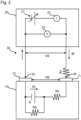
- Fig. 1 shows the case where the circuit building step S3 is performed after the voltage setting step S2.
- the leakage current measuring step S4 is performed after the voltage setting step S2 and the circuit building step S3, and is the step of measuring the leakage current flowing through the circuit until the leakage current converges.
- the voltage of the lithium-ion secondary battery having been left to stand for a certain period of time has dropped due to its self-discharge. This makes a potential difference between the test power supply and the lithium-ion secondary battery, and thus, the leakage current flows through the circuit.
- the increase of the leakage current also converges.
- the leakage current is measured at least until the increase of the leakage current converges.
- the determination step S5 is performed after the leakage current measuring step S4, and is the step of determining whether the lithium-ion secondary battery is good or bad based on the leakage current after having converged .
- the voltage of the lithium-ion secondary battery having been left to stand for a certain period of time has dropped due to its self-discharge.
- the amount of the voltage drop is larger when metallic foreign materials are contaminated in the lithium-ion secondary battery. This is accompanied with a larger value of the leakage current. Therefore, whether the battery is good or bad can be determined based on the value of the leakage current after having converged.
- a current value that is a standard for the determination whether the battery is good or bad may be appropriately set according to the target battery performance, and the like.
- circuits that can be built in the first embodiment are not limited to this.
- the circuit may be properly set according to the structure of the self-discharge measuring device.
- Fig. 2 shows the model circuit that is a typical example used in the first embodiment.
- a lithium-ion secondary battery 10 is provided with a cathode terminal 11 and an anode terminal 12.
- the lithium-ion secondary battery 10 of Fig. 2 is shown as a model comprising an electric generating element E, internal resistance Rs, and shunt resistance Rp.
- the internal resistance Rs and the electric generating element E are arranged in series.
- the shunt resistance Rp is a model of a conductive path formed by minute metallic foreign materials that may enter the lithium-ion secondary battery 10, and is arranged in parallel to the electric generating element E.
- a test power supply 20 has a DC power supply 21, an ammeter 22, a voltmeter 23, and probes 24 and 25.
- the ammeter 22 and the DC power supply 21 are arranged in series, and the voltmeter 23 is arranged in parallel to the DC power supply 21.
- the output voltage VS of the DC power supply 21 is adjustable.
- the DC power supply 21 is used to apply the output voltage VS to the lithium-ion secondary battery 10.
- the ammeter 22 is to measure the current flowing through a circuit 30.
- the voltmeter 23 is to measure the voltage between the probes 24 and 25.
- the probes 24 and 25 of the test power supply 20 are coupled to the cathode terminal 11 and the anode terminal 12 of the lithium-ion secondary battery 10, respectively, to build the circuit 30.
- the parasitic resistance Rx includes the lead resistance of each part of the test power supply 20, and the contact resistance between the probe 24 and the cathode terminal 11, and between the probe 25 and the anode terminal 25.
- the parasitic resistance Rx in the circuit 30 is drawn as if having been present in the lead on the probe 24 side only, which is, however, just for convenience of the drawing. Actually, the parasitic resistance Rx is present throughout the circuit 30.
- the charging rate of the lithium-ion secondary battery 10 is adjusted to be a predetermined charging rate that brings low temperature sensitivity (charging rate adjusting step S1). According to this, the influence of the battery temperature (environmental temperature) is suppressed, which allows whether the battery is good or bad to be determined with high accuracy in a short time.
- the battery voltage VB of the lithium-ion secondary battery 10 is measured, and the output voltage VS of the test power supply 20 is adjusted to be equal to the battery voltage VB (voltage setting step S2). Thereafter, the lithium-ion secondary battery 10 is connected to the test power supply 20 to build the circuit 30 (circuit building step S3). In the state just after the circuit is built, the output voltage VS is equal to the battery voltage VB. Thus, no potential difference is made, and the leakage current IB flowing through the circuit 30 is zero.
- the battery voltage VB of the lithium-ion secondary battery 10 having been left to stand for a certain period of time in this state has dropped due to its self-discharge.
- the drop of the battery voltage VB is, as described above, because of the self-discharge of the lithium-ion secondary battery 10.
- This self-discharge causes a self-discharge current ID to flow through the electric generating element E of the lithium-ion secondary battery 10.
- the leakage current IB flowing due to the drop of the battery voltage VB flows in the direction of charging the lithium-ion secondary battery 10.
- the leakage current IB acts to suppress the self-discharge of the lithium-ion secondary battery 10, and in the lithium-ion secondary battery 10, flows in the opposite direction of the self-discharge current ID.
- the leakage current IB increases so that the intensity thereof becomes the same as the self-discharge current ID, the self-discharge substantially stops. This is the reason why the increase of the leakage current IB converges.
- the shunt resistance Rp varies according to the minute metallic foreign materials contaminated in the battery.
- the leakage current IB of such a lithium-ion secondary battery 10 after having converged tends to be large.
- step S5 whether the lithium-ion secondary battery 10 is good or bad is determined based on the leakage current IB after having converged. Whether the leakage current IB converges or not may be determined by a known technique.
- the feature of the second embodiment is to raise the voltage of the test power supply over time in the leakage current measuring step S4 of the first embodiment. According to this, the time until the increase of the leakage current converges can be shortened. That is, the time for the leakage current measuring step can be shortened.
- the second embodiment will be described in detail.
- the drop of the battery voltage VB which accompanies the self-discharge of the lithium-ion secondary battery 10, causes the leakage current IB to increase.
- the leakage current IB increases to be equal to the self-discharge current ID
- the lithium-ion secondary battery 10 substantially stops discharging. Thereby, after this, the battery voltage VB and the leakage current IB are each constant. That is, the leakage current IB after having converged indicates the self-discharge current ID of the electric generating element E of the lithium-ion secondary battery 10.
- the output voltage VS is raised after the measurement starts.
- the equation (1) holds even in this case.
- the output voltage VS rises so that the leakage current IB increases faster than in the case where the output voltage VS is constant. Therefore, the time required for the leakage current IB to be equal to the self-discharge current ID shortens. This is the reason why the leakage current IB converges in an early stage. It is noted that raising the output voltage VS too much does not lead to proper convergence of the leakage current IB, and makes the determination whether the battery is good or bad difficult. Thus, it is necessary to limit the degree of the rise of the output voltage VS. Specifically, since the smaller the parasitic resistance Rx is, the larger the leakage current IB is, the output voltage VS is raised within such a range that the parasitic resistance Rx in the equation (1) seems to be smaller.
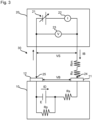
- Fig. 3 shows a model circuit in which the virtual resistance Rim is introduced.
- the virtual resistance Rim is a virtual resistance having a negative or zero resistance value.
- the virtual resistance Rim is inserted, so that the virtual resistance Rim and the parasitic resistance Rx are in series.
- the situation where the output voltage VS rises is considered by replacing the circuit with the model in which the output voltage VS is constant and the absolute value of the resistance value of the virtual resistance Rim rises instead.
- it is necessary that the sum of the parasitic resistance Rx and the virtual resistance Rim is positive (Rx + Rim > 0).
- the leakage current IB in the model circuit to which the virtual resistance Rim is introduced is expressed as the following equation (2).
- the measurement starts after the output voltage VS is matched to the battery voltage VB. Then, the output voltage VS is raised at a predetermined frequency according to the leakage current IB at this time, and according to the equation (3). Further, the leakage current IB increases as the output voltage VS rises (see the equation (1)). As described, in the second embodiment, the increase of the leakage current IB can be promoted, which can shorten the time until the increase of the leakage current IB converges.
- the frequency at which the output voltage VS is raised is not particularly limited. For example, the frequency may be approximately once per second. The frequency is not necessary to be regular.
- the rise of the output voltage VS for the increase of the leakage current IB is the product of the parasitic resistance Rx and the leakage current IB.
- the rise ⁇ VS is not limited to this, and may be the value obtained by multiplying the product in the formula (4) by a positive coefficient K that is less than 1.
- the coefficient K is any specific value as long as being within the above range, and may be fixed in advance.
- the parasitic resistance Rx including the contact resistance can be measured as follows. In the model circuit of Fig. 2 , the output voltage VS of the test power supply 20 is turned off, and the reading of the voltmeter 23 is measured in the following two states: the state where both the terminals of the test power supply 20 are connected via known resistance; and the state where this connection is broken. Then, the parasitic resistance Rx can be calculated based on the resistance value of the known resistance, and the two readings of the voltmeter 23.
- the voltage of the test power supply is set to be equal to that of the lithium-ion secondary battery in the voltage setting step S2.
- the feature of the third embodiment is that the voltage of the test power supply is set higher than that of the lithium-ion secondary battery. According to this, the time for the leakage current measuring step S4 can be shortened.
- the third embodiment will be described in detail.
- the voltage of the test power supply may be set to be equal to or higher than that of the lithium-ion secondary battery in the voltage setting step S2.
- the shunt resistance Rp of the model circuit of Fig. 2 is considered.
- the shunt resistance Rp is the model of minute metallic foreign materials contaminated in the battery.
- the self-discharge produced by the lithium-ion secondary battery 10 is the sum of the self-discharge present even if the battery is good, and the self-discharge due to minute metallic foreign materials.
- the shunt resistance Rp is the parallel resistance of natural shunt resistance Rp0 and foreign material shunt resistance Rp1 where the natural shunt resistance Rp0 is the resistance in the self-discharge path which is present even when the battery is good, and the foreign material shunt resistance Rp1 is the resistance in the lead paths by the minute metallic foreign materials. Therefore, the self-discharge current which is fixed by the battery voltage VB and the natural shunt resistance Rp0 is produced in the lithium-ion secondary battery 10 even when the battery is good. When the lithium-ion secondary battery 10 is bad, the self-discharge current is produced more based on the foreign material shunt resistance Rp1.
- the natural shunt resistance Rp0 is almost fixed by the design of the lithium-ion secondary battery 10. Therefore, the natural shunt resistance Rp0 can be treated as a known value according to the specifications of the lithium-ion secondary battery 10. As described above, the parasitic resistance Rx is also a known value. Thus, the right side of the equation (9) is formed of known values only. Therefore, the output voltage VS at the time point when the measurement starts can be easily fixed. According to the equation (9), the output voltage VS fixed in this way is higher than the battery voltage VB by "VB*(Rx/Rp0)".
- the self-discharge current ID0 is the initial self-discharge current of the lithium-ion secondary battery 10 when the battery is good.
- the equation (8) can be expressed as the following equation (10) with IDI.
- the output voltage VS at the time point when the measurement starts can be calculated by the equation (9) since the standard self-discharge current IDI is fixed by the natural shunt resistance Rp0, which is the design value, the battery voltage VB at the time point when the measurement starts, and the parasitic resistance Rx.
- VS VB + IDI * Rx
- the lithium-ion secondary battery 10 can be determined to be bad (initial current value ⁇ current converging value).
- the output voltage VS may be raised over time as in the second embodiment. According to this, the leakage current IB is allowed to converge in an early stage.
- a determination value of approximately 3 to 5 ⁇ A may be set for the increase of the leakage current IB. Then, whether the battery is a good or bad can be determined by determining whether or not the increase of the leakage current IB after the measurement starts is no less than the determination value. For example, approximately 20 to 30 minutes after the measurement starts may be set for the time point when the determination is performed.
- the method of testing the lithium-ion secondary battery of the present disclosure enables whether the battery is good or bad to be determined with high accuracy in a short time even when lithium iron phosphate is used as a cathode active material.
- a method of producing a lithium-ion secondary battery according to the present disclosure is as follows. That is, the method of producing a lithium-ion secondary battery comprises: the making step of making the lithium-ion secondary battery comprising a cathode containing lithium iron phosphate as a cathode active material, an anode containing a carbon material as an anode active material, and an electrolyte layer arranged between the cathode and the anode; and the testing step of performing the above-described testing method.
- the making step and the testing step have been described above, and thus, the descriptions thereof will be omitted here.
- the method of producing the lithium-ion secondary battery of the present disclosure enables whether the battery is good or bad to be determined with high accuracy in a short time, and thus, can suppress shipment of bad batteries, and shorten the production period.
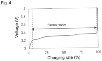
- a charging rate-voltage curve was obtained using a lithium-ion secondary battery having the following structure.
- the charging conditions were as follows: the voltage ranged from 3 to 3.75 V; and the current was at 0.05 C/s. The result is shown in Fig. 4 .
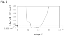
- Fig. 5 shows the correlation between the voltage and
- the plateau region of the lithium-ion secondary battery using lithium iron phosphate as a cathode active material was large.
- the region of the curve where the charging rate ranges from 7 to 99% corresponds to the plateau region.
- is no more than 0.005 V/mAh corresponds to the plateau region.
- a leakage current was measured using a lithium-ion secondary battery having the following structure.
- a testing device a self-discharge measuring device (BT2152B) manufactured by Keysight Technologies was used.
- the battery to be used for the test had been determined to be good, and was adjusted to be at a charging rate of 88%.
- This battery was connected to the testing device, and then, the leakage current was measured: the voltage of the testing device was equal to that of the battery.
- a battery to which external resistance was connected was used to imitate a bad battery.
- the battery temperature environment temperature
- the results are shown in Fig. 6 .
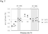
- Temperature sensitivity was measured using a lithium-ion secondary battery having the following structure. Specifically, the voltage of the battery was measured as the charging rate thereof was adjusted to those shown in table 1. In that time, the environmental temperature was changed to 20°C (6 h), 21°C (6 h), 20°C (6 h), 19°C (6 h), and 20°C (6 h) in this order. The temperature sensitivity ⁇ V/ ⁇ T (mV/°C) was calculated from each obtained voltage value V. The results are shown in table 1 and Fig. 7 . The correlation between the charging rate and the temperature sensitivity was in accordance with Nernst equation.
- the results of extremely low temperature sensitivity were obtained when the charging rate of the battery was in the range of 25 to 35% or 70 to 90%. Specifically, when the charging rate was in this range, the temperature sensitivity ⁇ V/ ⁇ T was within ⁇ 0.05 mV/°C. From this, it was found out that when the charging rate of the battery was in the range of 25 to 35% or 70 to 90%, the temperature sensitivity was low, and thus, the voltage change based on the temperature sensitivity was stable. Therefore, it was considered that whether the battery was good or bad can be determined with higher accuracy by adjusting the charging rate within the above range.
Landscapes
- Chemical & Material Sciences (AREA)
- General Physics & Mathematics (AREA)
- Physics & Mathematics (AREA)
- Engineering & Computer Science (AREA)
- Chemical Kinetics & Catalysis (AREA)
- Electrochemistry (AREA)
- General Chemical & Material Sciences (AREA)
- Manufacturing & Machinery (AREA)
- Materials Engineering (AREA)
- Inorganic Chemistry (AREA)
- Power Engineering (AREA)
- Secondary Cells (AREA)
- Battery Electrode And Active Subsutance (AREA)
- Tests Of Electric Status Of Batteries (AREA)
Claims (4)
- Verfahren zum Testen einer Lithium-Ionen-Sekundärbatterie, die Batterie umfassend eine Kathode, die Lithiumeisenphosphat als aktives Kathodenmaterial enthält, eine Anode, die ein Kohlenstoff-Material als aktives Anodenmaterial enthält, und eine Elektrolytschicht, die zwischen der Kathode und der Anode angeordnet ist, dadurch gekennzeichnet, dass das Verfahren Folgendes umfasst:Anpassen einer Laderate der Lithium-Ionen-Sekundärbatterie, so dass sie in einem Plateaubereich ist und in dem Bereich von 25 bis 35 % oder 70 bis 90 % ist;Einstellen der Spannung einer Teststromversorgung auf eine Spannung, die größer oder gleich der Spannung der Lithium-Ionen-Sekundärbatterie ist;Aufbauen eines Stromkreises durch Verbinden der Lithium-Ionen-Sekundärbatterie und der Teststromversorgung;Messen eines Leckstroms, der durch den Stromkreis fließt, bis der Leckstrom konvergiert; undBestimmen, ob die Lithium-Ionen-Sekundärbatterie gut oder schlecht ist, auf der Grundlage des Leckstroms, nachdem der Leckstrom konvergiert ist.
- Verfahren nach Anspruch 1, wobei bei dem Messen eines Leckstroms die Spannung der Teststromversorgung mit der Zeit erhöht wird.
- Verfahren nach Anspruch 1 oder 2, wobei bei dem Anpassen einer Laderate die Laderate der Lithium-Ionen-Sekundärbatterie so angepasst wird, dass dV/dT - 0,05 mV/°C bis 0,05 mV/°C ist, wobei V die Spannung der Lithium-Ionen-Sekundärbatterie ist und T eine Temperatur der Lithium-Ionen-Sekundärbatterie ist.
- Verfahren zum Herstellen einer Lithium-Ionen-Sekundärbatterie, das Verfahren Folgendes umfassend:Anfertigen der Lithium-Ionen-Sekundärbatterie, die eine Kathode, die Lithiumeisenphosphat als aktives Kathodenmaterial enthält, eine Anode, die ein Kohlenstoff-Material als aktives Anodenmaterial enthält, und eine Elektrolytschicht umfasst, die zwischen der Kathode und der Anode angeordnet ist; undDurchführen des Testverfahrens nach Anspruch 1 oder 2.
Applications Claiming Priority (1)
| Application Number | Priority Date | Filing Date | Title |
|---|---|---|---|
| JP2022203121A JP2024088111A (ja) | 2022-12-20 | 2022-12-20 | リチウムイオン二次電池の検査方法及びこれを用いた製造方法 |
Publications (2)
| Publication Number | Publication Date |
|---|---|
| EP4390415A1 EP4390415A1 (de) | 2024-06-26 |
| EP4390415B1 true EP4390415B1 (de) | 2025-06-11 |
Family
ID=88833657
Family Applications (1)
| Application Number | Title | Priority Date | Filing Date |
|---|---|---|---|
| EP23209318.7A Active EP4390415B1 (de) | 2022-12-20 | 2023-11-13 | Verfahren zum testen einer lithium-ionen-sekundärbatterie und verfahren zur herstellung einer lithium-ionen-sekundärbatterie damit |
Country Status (5)
| Country | Link |
|---|---|
| US (1) | US20240201283A1 (de) |
| EP (1) | EP4390415B1 (de) |
| JP (1) | JP2024088111A (de) |
| KR (1) | KR102806522B1 (de) |
| CN (1) | CN118226256A (de) |
Family Cites Families (1)
| Publication number | Priority date | Publication date | Assignee | Title |
|---|---|---|---|---|
| JP7000847B2 (ja) | 2017-12-25 | 2022-01-19 | トヨタ自動車株式会社 | 蓄電デバイスの検査方法および製造方法 |
-
2022
- 2022-12-20 JP JP2022203121A patent/JP2024088111A/ja active Pending
-
2023
- 2023-09-08 US US18/463,722 patent/US20240201283A1/en active Pending
- 2023-10-24 KR KR1020230143190A patent/KR102806522B1/ko active Active
- 2023-11-13 EP EP23209318.7A patent/EP4390415B1/de active Active
- 2023-12-08 CN CN202311678014.4A patent/CN118226256A/zh active Pending
Also Published As
| Publication number | Publication date |
|---|---|
| KR102806522B1 (ko) | 2025-05-12 |
| JP2024088111A (ja) | 2024-07-02 |
| KR20240097717A (ko) | 2024-06-27 |
| CN118226256A (zh) | 2024-06-21 |
| US20240201283A1 (en) | 2024-06-20 |
| EP4390415A1 (de) | 2024-06-26 |
Similar Documents
| Publication | Publication Date | Title |
|---|---|---|
| US11824172B2 (en) | Method and system for producing nonaqueous electrolyte secondary battery | |
| US10317477B2 (en) | Inspection method and manufacturing method of secondary battery | |
| US8125185B2 (en) | Method for charging non-aqueous electrolyte secondary battery | |
| US9190864B2 (en) | Charging control method for secondary cell and charging control device for secondary cell | |
| JP2014222603A (ja) | 電池の検査方法 | |
| EP3370299B1 (de) | Ladeverfahren einer lithium-ionen-batterie bei nichtkonstanter spannung zur korrektur und kompensation von spannung | |
| JP2012212513A (ja) | リチウム二次電池の状態検出方法 | |
| JP2009145137A (ja) | 二次電池の検査方法 | |
| WO2013069459A1 (ja) | 二次電池の制御装置およびsoc検出方法 | |
| EP3425412B1 (de) | Reaktionsschätzverfahren für sekundärbatterie und sekundärbatterie mit batteriezelle dafür | |
| JP2016048213A (ja) | 電池の評価方法及び電池特性評価装置 | |
| Raijmakers et al. | A new method to compensate impedance artefacts for Li-ion batteries with integrated micro-reference electrodes | |
| Koch et al. | A versatile reference electrode for lithium ion battery use | |
| US12334769B2 (en) | Method for establishing lithium secondary battery charging protocol, battery management system, battery pack, and battery cell charging device | |
| JP2014082121A (ja) | 非水電解液二次電池の製造方法 | |
| Jow et al. | Electrolytes, SEI and charge discharge kinetics in Li-ion batteries | |
| EP4390415B1 (de) | Verfahren zum testen einer lithium-ionen-sekundärbatterie und verfahren zur herstellung einer lithium-ionen-sekundärbatterie damit | |
| JP2023083043A (ja) | 非水電解液二次電池の検査方法 | |
| US20250105359A1 (en) | Lithium ion cell, battery pack, and electricity-consumption device | |
| US20250343431A1 (en) | Battery management system, battery pack including same, and method of establishing charging protocol of lithium secondary battery | |
| KR102885117B1 (ko) | 저전압 불량 전지셀 평가 방법 | |
| JP2023007669A (ja) | バッテリの検査方法 | |
| CN106537677B (zh) | 制造非水二次电池的方法 | |
| US12614761B2 (en) | Nonaqueous electrolyte secondary battery, and method for fabricating nonaqueous electrolyte secondary battery | |
| EP4106066A2 (de) | Sekundärbatterie mit nichtwässrigem elektrolyt und verfahren zur herstellung der sekundärbatterie mit nichtwässrigem elektrolyt |
Legal Events
| Date | Code | Title | Description |
|---|---|---|---|
| PUAI | Public reference made under article 153(3) epc to a published international application that has entered the european phase |
Free format text: ORIGINAL CODE: 0009012 |
|
| STAA | Information on the status of an ep patent application or granted ep patent |
Free format text: STATUS: REQUEST FOR EXAMINATION WAS MADE |
|
| 17P | Request for examination filed |
Effective date: 20231124 |
|
| AK | Designated contracting states |
Kind code of ref document: A1 Designated state(s): AL AT BE BG CH CY CZ DE DK EE ES FI FR GB GR HR HU IE IS IT LI LT LU LV MC ME MK MT NL NO PL PT RO RS SE SI SK SM TR |
|
| GRAP | Despatch of communication of intention to grant a patent |
Free format text: ORIGINAL CODE: EPIDOSNIGR1 |
|
| STAA | Information on the status of an ep patent application or granted ep patent |
Free format text: STATUS: GRANT OF PATENT IS INTENDED |
|
| INTG | Intention to grant announced |
Effective date: 20250127 |
|
| RIC1 | Information provided on ipc code assigned before grant |
Ipc: G01R 31/385 20190101ALI20250117BHEP Ipc: G01R 31/36 20200101AFI20250117BHEP |
|
| GRAS | Grant fee paid |
Free format text: ORIGINAL CODE: EPIDOSNIGR3 |
|
| GRAA | (expected) grant |
Free format text: ORIGINAL CODE: 0009210 |
|
| STAA | Information on the status of an ep patent application or granted ep patent |
Free format text: STATUS: THE PATENT HAS BEEN GRANTED |
|
| P01 | Opt-out of the competence of the unified patent court (upc) registered |
Free format text: CASE NUMBER: APP_20540/2025 Effective date: 20250430 |
|
| AK | Designated contracting states |
Kind code of ref document: B1 Designated state(s): AL AT BE BG CH CY CZ DE DK EE ES FI FR GB GR HR HU IE IS IT LI LT LU LV MC ME MK MT NL NO PL PT RO RS SE SI SK SM TR |
|
| REG | Reference to a national code |
Ref country code: GB Ref legal event code: FG4D |
|
| REG | Reference to a national code |
Ref country code: CH Ref legal event code: EP |
|
| REG | Reference to a national code |
Ref country code: DE Ref legal event code: R096 Ref document number: 602023003954 Country of ref document: DE |
|
| REG | Reference to a national code |
Ref country code: IE Ref legal event code: FG4D |
|
| PG25 | Lapsed in a contracting state [announced via postgrant information from national office to epo] |
Ref country code: ES Free format text: LAPSE BECAUSE OF FAILURE TO SUBMIT A TRANSLATION OF THE DESCRIPTION OR TO PAY THE FEE WITHIN THE PRESCRIBED TIME-LIMIT Effective date: 20250611 Ref country code: FI Free format text: LAPSE BECAUSE OF FAILURE TO SUBMIT A TRANSLATION OF THE DESCRIPTION OR TO PAY THE FEE WITHIN THE PRESCRIBED TIME-LIMIT Effective date: 20250611 |
|
| REG | Reference to a national code |
Ref country code: LT Ref legal event code: MG9D |
|
| PG25 | Lapsed in a contracting state [announced via postgrant information from national office to epo] |
Ref country code: GR Free format text: LAPSE BECAUSE OF FAILURE TO SUBMIT A TRANSLATION OF THE DESCRIPTION OR TO PAY THE FEE WITHIN THE PRESCRIBED TIME-LIMIT Effective date: 20250912 Ref country code: NO Free format text: LAPSE BECAUSE OF FAILURE TO SUBMIT A TRANSLATION OF THE DESCRIPTION OR TO PAY THE FEE WITHIN THE PRESCRIBED TIME-LIMIT Effective date: 20250911 |
|
| REG | Reference to a national code |
Ref country code: NL Ref legal event code: MP Effective date: 20250611 |
|
| PG25 | Lapsed in a contracting state [announced via postgrant information from national office to epo] |
Ref country code: BG Free format text: LAPSE BECAUSE OF FAILURE TO SUBMIT A TRANSLATION OF THE DESCRIPTION OR TO PAY THE FEE WITHIN THE PRESCRIBED TIME-LIMIT Effective date: 20250611 |
|
| PG25 | Lapsed in a contracting state [announced via postgrant information from national office to epo] |
Ref country code: HR Free format text: LAPSE BECAUSE OF FAILURE TO SUBMIT A TRANSLATION OF THE DESCRIPTION OR TO PAY THE FEE WITHIN THE PRESCRIBED TIME-LIMIT Effective date: 20250611 |
|
| PGFP | Annual fee paid to national office [announced via postgrant information from national office to epo] |
Ref country code: FR Payment date: 20250930 Year of fee payment: 3 |
|
| PG25 | Lapsed in a contracting state [announced via postgrant information from national office to epo] |
Ref country code: RS Free format text: LAPSE BECAUSE OF FAILURE TO SUBMIT A TRANSLATION OF THE DESCRIPTION OR TO PAY THE FEE WITHIN THE PRESCRIBED TIME-LIMIT Effective date: 20250911 |
|
| PG25 | Lapsed in a contracting state [announced via postgrant information from national office to epo] |
Ref country code: LV Free format text: LAPSE BECAUSE OF FAILURE TO SUBMIT A TRANSLATION OF THE DESCRIPTION OR TO PAY THE FEE WITHIN THE PRESCRIBED TIME-LIMIT Effective date: 20250611 |
|
| PG25 | Lapsed in a contracting state [announced via postgrant information from national office to epo] |
Ref country code: NL Free format text: LAPSE BECAUSE OF FAILURE TO SUBMIT A TRANSLATION OF THE DESCRIPTION OR TO PAY THE FEE WITHIN THE PRESCRIBED TIME-LIMIT Effective date: 20250611 |
|
| PG25 | Lapsed in a contracting state [announced via postgrant information from national office to epo] |
Ref country code: PT Free format text: LAPSE BECAUSE OF FAILURE TO SUBMIT A TRANSLATION OF THE DESCRIPTION OR TO PAY THE FEE WITHIN THE PRESCRIBED TIME-LIMIT Effective date: 20251013 |
|
| REG | Reference to a national code |
Ref country code: AT Ref legal event code: MK05 Ref document number: 1802676 Country of ref document: AT Kind code of ref document: T Effective date: 20250611 |
|
| PG25 | Lapsed in a contracting state [announced via postgrant information from national office to epo] |
Ref country code: IS Free format text: LAPSE BECAUSE OF FAILURE TO SUBMIT A TRANSLATION OF THE DESCRIPTION OR TO PAY THE FEE WITHIN THE PRESCRIBED TIME-LIMIT Effective date: 20251011 |
|
| PGFP | Annual fee paid to national office [announced via postgrant information from national office to epo] |
Ref country code: DE Payment date: 20250930 Year of fee payment: 3 |
|
| PG25 | Lapsed in a contracting state [announced via postgrant information from national office to epo] |
Ref country code: AT Free format text: LAPSE BECAUSE OF FAILURE TO SUBMIT A TRANSLATION OF THE DESCRIPTION OR TO PAY THE FEE WITHIN THE PRESCRIBED TIME-LIMIT Effective date: 20250611 Ref country code: SM Free format text: LAPSE BECAUSE OF FAILURE TO SUBMIT A TRANSLATION OF THE DESCRIPTION OR TO PAY THE FEE WITHIN THE PRESCRIBED TIME-LIMIT Effective date: 20250611 |
|
| PG25 | Lapsed in a contracting state [announced via postgrant information from national office to epo] |
Ref country code: CZ Free format text: LAPSE BECAUSE OF FAILURE TO SUBMIT A TRANSLATION OF THE DESCRIPTION OR TO PAY THE FEE WITHIN THE PRESCRIBED TIME-LIMIT Effective date: 20250611 |
|
| PG25 | Lapsed in a contracting state [announced via postgrant information from national office to epo] |
Ref country code: PL Free format text: LAPSE BECAUSE OF FAILURE TO SUBMIT A TRANSLATION OF THE DESCRIPTION OR TO PAY THE FEE WITHIN THE PRESCRIBED TIME-LIMIT Effective date: 20250611 |
|
| PG25 | Lapsed in a contracting state [announced via postgrant information from national office to epo] |
Ref country code: EE Free format text: LAPSE BECAUSE OF FAILURE TO SUBMIT A TRANSLATION OF THE DESCRIPTION OR TO PAY THE FEE WITHIN THE PRESCRIBED TIME-LIMIT Effective date: 20250611 |
|
| PG25 | Lapsed in a contracting state [announced via postgrant information from national office to epo] |
Ref country code: SK Free format text: LAPSE BECAUSE OF FAILURE TO SUBMIT A TRANSLATION OF THE DESCRIPTION OR TO PAY THE FEE WITHIN THE PRESCRIBED TIME-LIMIT Effective date: 20250611 |
|
| PG25 | Lapsed in a contracting state [announced via postgrant information from national office to epo] |
Ref country code: RO Free format text: LAPSE BECAUSE OF FAILURE TO SUBMIT A TRANSLATION OF THE DESCRIPTION OR TO PAY THE FEE WITHIN THE PRESCRIBED TIME-LIMIT Effective date: 20250611 |
|
| PG25 | Lapsed in a contracting state [announced via postgrant information from national office to epo] |
Ref country code: DK Free format text: LAPSE BECAUSE OF FAILURE TO SUBMIT A TRANSLATION OF THE DESCRIPTION OR TO PAY THE FEE WITHIN THE PRESCRIBED TIME-LIMIT Effective date: 20250611 |
|
| PG25 | Lapsed in a contracting state [announced via postgrant information from national office to epo] |
Ref country code: IT Free format text: LAPSE BECAUSE OF FAILURE TO SUBMIT A TRANSLATION OF THE DESCRIPTION OR TO PAY THE FEE WITHIN THE PRESCRIBED TIME-LIMIT Effective date: 20250611 |
|
| PLBE | No opposition filed within time limit |
Free format text: ORIGINAL CODE: 0009261 |
|
| STAA | Information on the status of an ep patent application or granted ep patent |
Free format text: STATUS: NO OPPOSITION FILED WITHIN TIME LIMIT |
|
| REG | Reference to a national code |
Ref country code: CH Ref legal event code: L10 Free format text: ST27 STATUS EVENT CODE: U-0-0-L10-L00 (AS PROVIDED BY THE NATIONAL OFFICE) Effective date: 20260423 |