EP4389587B1 - Antriebsvorrichtung zum ausüben von schub auf ein fluid - Google Patents
Antriebsvorrichtung zum ausüben von schub auf ein fluid Download PDFInfo
- Publication number
- EP4389587B1 EP4389587B1 EP22214638.3A EP22214638A EP4389587B1 EP 4389587 B1 EP4389587 B1 EP 4389587B1 EP 22214638 A EP22214638 A EP 22214638A EP 4389587 B1 EP4389587 B1 EP 4389587B1
- Authority
- EP
- European Patent Office
- Prior art keywords
- propulsive
- guide element
- propulsion device
- distance
- hub
- Prior art date
- Legal status (The legal status is an assumption and is not a legal conclusion. Google has not performed a legal analysis and makes no representation as to the accuracy of the status listed.)
- Active
Links
Images



Classifications
-
- B—PERFORMING OPERATIONS; TRANSPORTING
- B63—SHIPS OR OTHER WATERBORNE VESSELS; RELATED EQUIPMENT
- B63H—MARINE PROPULSION OR STEERING
- B63H1/00—Propulsive elements directly acting on water
- B63H1/02—Propulsive elements directly acting on water of rotary type
- B63H1/12—Propulsive elements directly acting on water of rotary type with rotation axis substantially in propulsive direction
- B63H1/14—Propellers
- B63H1/26—Blades
-
- B—PERFORMING OPERATIONS; TRANSPORTING
- B63—SHIPS OR OTHER WATERBORNE VESSELS; RELATED EQUIPMENT
- B63H—MARINE PROPULSION OR STEERING
- B63H1/00—Propulsive elements directly acting on water
- B63H1/02—Propulsive elements directly acting on water of rotary type
- B63H1/12—Propulsive elements directly acting on water of rotary type with rotation axis substantially in propulsive direction
- B63H1/14—Propellers
-
- B—PERFORMING OPERATIONS; TRANSPORTING
- B63—SHIPS OR OTHER WATERBORNE VESSELS; RELATED EQUIPMENT
- B63H—MARINE PROPULSION OR STEERING
- B63H1/00—Propulsive elements directly acting on water
- B63H1/02—Propulsive elements directly acting on water of rotary type
- B63H1/12—Propulsive elements directly acting on water of rotary type with rotation axis substantially in propulsive direction
- B63H1/14—Propellers
- B63H1/20—Hubs; Blade connections
-
- B—PERFORMING OPERATIONS; TRANSPORTING
- B64—AIRCRAFT; AVIATION; COSMONAUTICS
- B64C—AEROPLANES; HELICOPTERS
- B64C11/00—Propellers, e.g. of ducted type; Features common to propellers and rotors for rotorcraft
- B64C11/16—Blades
- B64C11/18—Aerodynamic features
-
- B—PERFORMING OPERATIONS; TRANSPORTING
- B64—AIRCRAFT; AVIATION; COSMONAUTICS
- B64C—AEROPLANES; HELICOPTERS
- B64C11/00—Propellers, e.g. of ducted type; Features common to propellers and rotors for rotorcraft
- B64C11/16—Blades
- B64C11/20—Constructional features
-
- B—PERFORMING OPERATIONS; TRANSPORTING
- B64—AIRCRAFT; AVIATION; COSMONAUTICS
- B64C—AEROPLANES; HELICOPTERS
- B64C11/00—Propellers, e.g. of ducted type; Features common to propellers and rotors for rotorcraft
- B64C11/16—Blades
- B64C11/20—Constructional features
- B64C11/24—Hollow blades
-
- B—PERFORMING OPERATIONS; TRANSPORTING
- B64—AIRCRAFT; AVIATION; COSMONAUTICS
- B64C—AEROPLANES; HELICOPTERS
- B64C11/00—Propellers, e.g. of ducted type; Features common to propellers and rotors for rotorcraft
- B64C11/46—Arrangements of, or constructional features peculiar to, multiple propellers
- B64C11/48—Units of two or more coaxial propellers
-
- B—PERFORMING OPERATIONS; TRANSPORTING
- B63—SHIPS OR OTHER WATERBORNE VESSELS; RELATED EQUIPMENT
- B63H—MARINE PROPULSION OR STEERING
- B63H1/00—Propulsive elements directly acting on water
- B63H1/02—Propulsive elements directly acting on water of rotary type
- B63H1/12—Propulsive elements directly acting on water of rotary type with rotation axis substantially in propulsive direction
- B63H1/14—Propellers
- B63H2001/145—Propellers comprising blades of two or more different types, e.g. different lengths
-
- B—PERFORMING OPERATIONS; TRANSPORTING
- B64—AIRCRAFT; AVIATION; COSMONAUTICS
- B64C—AEROPLANES; HELICOPTERS
- B64C11/00—Propellers, e.g. of ducted type; Features common to propellers and rotors for rotorcraft
Definitions
- the present disclosure relates generally to the field of propulsion devices for generating thrust to a fluid.
- the propulsion device disclosed herein may be used at various applications such as for the propulsion of vessels including both marine and airborne vessels including drones and for the generation of a forced fluid flow, such as at fans, blowers and liquid pumps.
- Traditional screw-propellers typically comprise a rotational hub with two or more blades which are fixed to the hub and protrude radially therefrom.
- the blades are arranged with a pitch such as to define a helical spiral resembling a helical screw line.
- Such traditional screw-propellers typically present a comparatively high rotational resistance which results in high motor load and low energy efficiency.
- the traditional screw-propellers are also exposed to cavitation which in turn may damage the blades, cause undesirable vibrations, and give rise to noise. Additionally, such traditional screw-propellers typically exhibit a substantial slip which further reduces the energy efficiency.
- GB 188,206 discloses a screw-propeller comprising a hub and a plurality of radiating supporting main blades fixed to the hub. Each main blade is connected a first auxiliary blade arranged in front of the main blade and to a second auxiliary blade arranged behind the main blade. The tips of the main blades and the auxiliary blades extend radially beyond the connections between the main and the auxiliary blades.
- US 2021/354801 A1 discloses a propeller assembly with groups of three axially aligned blades attached to a central hub that are capped by an outer guide element.
- An object of the present invention is to provide an enhanced propulsion device for generating thrust to a fluid.
- Another object is to provide such a propulsion device which exhibits a high efficiency.
- a further object is to provide such a propulsion device which generates an axial flow with a comparatively very small separation.
- Yet another object is to provide such a propulsion device which exhibits comparatively low resistance to the fluid.
- Still another objective is to provide such a propulsion device which prevents cavitation.
- a further object is to provide such a propulsion device which provides a comparatively low slip.
- the present disclosure provides a propulsion device as set out in the appended claim 1.
- the propulsion device is arranged for exerting thrust to a fluid.
- the propulsion device comprises a central hub having a front end and a rear end and is rotational about a rotational axis extending longitudinally between the front and rear ends, and at least two propulsive arrangements which protrude radially from the hub and which are evenly distributed about the circumference of the hub.
- Each propulsive arrangement comprises a front propulsive element which extends radially from a front inner end to a front outer end, a rear propulsive element which extends radially from a rear inner end to a rear outer end.
- An outer guide element extends from the front outer end to the rear outer end at a radial outer guide element distance from the rotational axis and an inner guide element extends from the front inner end to the rear inner end at a radial inner guide element distance from the rotational axis.
- An elongate front distance member and an elongate rear distance member extend radially from the hub to the inner guide element.
- At least one intermediate propulsive element is arranged between the front and rear propulsive elements and extends radially from the inner guide element to the outer guide element.
- the longitudinal projections of the front propulsive element, the intermediate propulsive element and the rear propulsive element overlap at least partially.
- the inner guide element, the front distance member, the rear distance member and the periphery of the hub define an open space allowing free passage of the fluid.
- the propulsion device By providing the propulsion device with an intermediate propulsive element which extends from an inner guide element arranged radially at a distance from the hub, the propulsion device provides additional thrust generating surface at a peripheral portion of the propulsion device. Thrust generating area arranged at the peripheral portion of the propulsion device provides higher trust and lower resistance in the axial and tangential direction than blade area at the central portion of traditional screw-propellers.
- the intermediate propulsive element thus increases the efficiency of the propulsion device by increasing the thrust while maintaining the resistance low.
- the inner guide element and outer guide element which extend longitudinally between all propulsive elements in one propulsive arrangement reduce radial flow and promote the generation of flows in the axial direction.
- the axial component of the flow generated by the propulsion device is increased while keeping the lateral separation of the flow low. This also contributes to increase the efficiency of the propulsion device.
- the outer guide element and inner guide element also increase the rigidity of the propulsion device, thus allowing the propulsive elements to be comparatively thin and reducing vibrations.
- the outer guide element further reduces cavitation at the peripheral portion of the propulsive elements, which in turn reduces wear of the propulsive elements as well as noise and other vibrations.
- the propulsion device has proven to exhibit high efficiency, low resistance, both in the axial and circumferential directions, a highly concentrated axial flow with small lateral separation, low degree of cavitation and low levels of noise and other vibrations.
- the longitudinal projections of the front propulsive element, the intermediate propulsive element and the rear propulsive element fully overlaps. This results in a further reduction of axial resistance.
- the lengths of the axial projection of the chord lines of the front, rear and intermediate propulsive element may be essentially constant.
- the axial projection of the propulsive elements thus exhibits a rectangular or rhomboid shape.
- the active propulsive element area may be large while maintaining the chord lines short. This in turn increases the thrust while minimizing cavitation.
- the maximal chord line of each of the front, rear and intermediate propulsive elements may be a short chord line.
- a short chord line is defined by NACA standard nomenclature.
- the inner guide element distance (IG) may be at least 40% of the outer guide distance (OG). This means that the intermediate propulsive element is positioned at a sufficient distance from the rotational axis for providing great thrust in relation to the resistance.
- the outer guide element may protrude rearwardly from the rear outer end.
- the protruding portion of the outer guide element then provides a so-called winglet which efficiently reduces cavitation.
- the outer guide element and the inner guide element may exhibit an essentially constant longitudinal cross section which is outwardly convex. This reduces the resistance in the circumferential direction.
- the outer guide element and the inner guide element may exhibit an essentially constant longitudinal cross section which is inwardly concave. This further reduces the resistance in the circumferential direction.
- the radius of the convex or concave curvature may be essentially equal to the radial distance from the rotational axis to the respective outer guide element and inner guide element. This also reduces the resistance in the circumferential direction.
- each front, rear and intermediate propulsive element may be essentially constant. This also allows a large active propulsive elements area while keeping the chord line comparatively short.
- the front distance member and the rear distance member may be longitudinally aligned.
- the front distance member and the rear distance member may be arranged as radial extensions from the front inner end and the rear inner end respectively to the hub.
- Each propulsive arrangement may comprise a plurality, preferably two or three intermediate propulsive elements.
- the advantages of arranging active propulsive elements area at the periphery of the propulsion device is further enhanced.
- the propulsion device may comprise two propulsive arrangements mutually separated in the circumferential direction by 180° or three propulsive arrangements mutually separated in the circumferential direction by 120° or four propulsive arrangements mutually separated in the circumferential direction by 90° or five propulsive arrangements mutually separated in the circumferential direction by 72° or six propulsive arrangements mutually separated in the circumferential direction by 60°.
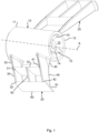
- the marine propulsion device comprises a central hub 10 which is rotational about a central rotational axis A.
- the hub 10 is arranged for passing exhaust gases from an outboard or inboard engine (not shown) through the interior of the hub.
- the hub is conical end tappers from a front end 11 to a rear end 12.
- the hub 10 exhibits a central bore 13 extending longitudinally from the front end 11 to the rear end 12.
- a cylindrical internally splined sleeve member 14 extends centrally through the bore 13.
- the sleeve member 14 is fixed to the inner wall of the bore 13 by means of four radial struts 15 such that an annular channel for expelling exhaust gases is formed in the bore 13 around the sleeve member 14.
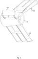
- the propulsive arrangements 20 each comprise a front propulsive element 30, a rear propulsive element 40 and an intermediate propulsive element 50.
- the front propulsive element 30 exhibits a front inner end 31 and a front outer end 32.
- the rear propulsive element 40 exhibits a rear inner end 41 and a rear outer end 42.
- An outer guide element 60 extends in parallel with the rotational axis A, from the front outer end 32 to the rear outer end 42.
- the outer guide 60 is arranged at a radial outer guide element distance OG from the rotational axis A.
- the outer guide element 60 protrudes axially a short distance rearwardly of the rear propulsive element 40, forming a rearwardly protruding winglet 61.
- An inner guide element 70 extends in parallel with the rotational axis A from the front inner end 31 to the rear inner end 41.
- the inner guide element 70 is fixed to the periphery of the hub by means of an elongate front distance member 35 and an elongate rear distance member 45.
- the distance members 35, 45 each extend radially from the hub to the inner guide element 70.
- the front distance member 35 forms a radially inwardly directed extension of the front propulsive element 30
- the rear distance member forms a radially inwardly directed extension of the rear propulsive element 40.
- the distance members may be arranged at other longitudinal positions of the inner guide element, as long as they hold the inner guide element 70 at a radial distance from the hub 10.
- the inner guide element 70 is arranged at a radial inner guide element distance IG from the rotational axis A.
- the inner guide element distance IG is shorter than the outer guide distance OG but larger than the maximum outer diameter of the hub 10. I.e. the inner guide element 70 is arranged radially between the outer periphery of the hub and the outer guide element 60.
- the inner guide element distance IG is approx. 60 % of the outer guide element distance OG. It is preferred that the inner guide element distance IG is between 40% and 75% of the outer guide element distance OG.
- the radially outer surface of the outer guide element 60 is convex with a radius of curvature which is essentially equal to the outer guide element distance OG.
- the radially inner surface of the outer guide element 60 is concave also with a radius of curvature which is essentially equal to the outer guide element distance OG.
- the inner guide element 70 has an outer convex surface and an inner concave surface, both of which exhibit a radius of curvature which is essentially equal to the inner guide element distance IG.
- the circumferential resistance of the propulsion device is reduced.
- the intermediate propulsive element 50 is arranged longitudinally at the centre between the front propulsive element 30 and the rear propulsive element 40 and extends radially from the inner guide element 70 to the outer guide element 60.
- the intermediate propulsive element 50 has an intermediate inner end 51 which is fixed to the inner guide 70 and an intermediate outer end 52 which is fixed to the outer guide 60.
- the front distance member 35, the rear distance member 45, the periphery of the hub 10 and the inner guide element 70 define an open space through which the fluid, which in this case is water, may flow freely and which does not present any axial or circumferential resistance as the propulsion device rotates.
- the front 30, rear 40 and intermediate propulsive elements 50 exhibit essentially identical geometries. At each propulsive element 30, 40, 50 the leading edge is arranged essentially in parallel with the trailing edge. Further, the axial projection of the propulsive elements is essentially rhombic. Additionally, the widths in the circumferential direction of the propulsive elements 30, 40, 50, the inner guide element 70 and the outer guide element 60 are essentially equal.
- the width in the circumferential direction of the propulsive elements 30, 40, 50 may also be expressed by the length of the chord line (or chord) extending through the respective propulsive element from the leading edge to the trailing edge and by the axial projection of this chord line.
- Fig 3 illustrates a second embodiment of the propulsion device comprising a hub 110 and three propulsive arrangements 120 distributed along the periphery of the hub 110 and separated by 120°.
- Fig 4 illustrates a third embodiment of the propulsion device comprising a hub 210 and four propulsive arrangements 220 distributed along the periphery of the hub 210 and separated by 90 °.
- the hub 110, 210 and each propulsive arrangement 120, 220 are essentially equal to the hub 10 and the propulsive arrangement 20 shown in figs. 1 - 2c and described above and the description is not repeated here.
- each propulsive arrangement may comprise more than one intermediate propulsive element arranged between a front and a rear propulsive element.
- the intermediate propulsive elements extend radially between an inner guide element which is arranged at a distance from the hub and an outer guide element, which outer guide element extends between the outer end of the front and rear propulsive elements.
- each propulsive arrangement comprises a total number of active propulsive elements arranged between the inner guide element and the outer guide element which is equal to the sum of intermediate propulsive element plus two.
- each propulsive arrangement may comprise more than two elongate distance members connecting the inner guide element to the hub.
- propulsive elements in a propulsive arrangement are aligned longitudinally and fully overlap each other in the longitudinal direction.
Landscapes
- Engineering & Computer Science (AREA)
- Aviation & Aerospace Engineering (AREA)
- Chemical & Material Sciences (AREA)
- Combustion & Propulsion (AREA)
- Mechanical Engineering (AREA)
- Ocean & Marine Engineering (AREA)
- Physics & Mathematics (AREA)
- Fluid Mechanics (AREA)
- Structures Of Non-Positive Displacement Pumps (AREA)
- Tires In General (AREA)
- Portable Nailing Machines And Staplers (AREA)
Claims (14)
- Antriebsvorrichtung zum Ausüben von Schub auf ein Fluid, die eine mittige Nabe (10, 110, 210), die ein vorderes Ende (11) und ein hinteres Ende (12) aufweist und um eine Drehachse (A) drehbar ist, die sich in Längsrichtung zwischen dem vorderen (11) und dem hinteren (12) Ende erstreckt, und mindestens zwei Antriebsanordnungen (20, 120, 220), die in Radialrichtung von der Nabe (10, 110, 210) aus vorspringen und die gleichmäßig um den Umfang der Nabe (10, 110, 210) angeordnet sind, umfasst, wobei jede Antriebsanordnung (20, 120, 220) Folgendes umfasst:- ein vorderes Antriebselement (30), das sich in Radialrichtung von einem vorderen inneren Ende (31) bis zu einem vorderen äußeren Ende (32) erstreckt,- ein hinteres Antriebselement (40), das sich in Radialrichtung von einem hinteren inneren Ende (41) bis zu einem hinteren äußeren Ende (42) erstreckt,- ein äußeres Führungselement (60), das sich von dem vorderen äußeren Ende (32) bis zu dem hinteren äußeren Ende (42) in einer radialen äußeren Führungselemententfernung (OG) von der Drehachse (A) erstreckt,- ein inneres Führungselement (70), das sich von dem vorderen inneren Ende (31) bis zu dem hinteren inneren Ende (41) in einer radialen inneren Führungselemententfernung (IG) von der Drehachse (A) erstreckt,- ein längliches vorderes Abstandselement (35) und ein längliches hinteres Abstandselement (45), wobei sich die Abstandselemente (35, 45) in Radialrichtung von der Nabe (10) bis zu dem inneren Führungselement (60) erstrecken, und- mindestens ein dazwischenliegendes Antriebselement (50), das zwischen dem vorderen (30) und dem hinteren (40) Antriebselement angeordnet ist und sich in Radialrichtung, von dem inneren Führungselement (70) aus, bis zu dem äußeren Führungselement (60) erstreckt, wobei- die Längsprojektionen des vorderen Antriebselements (30), des dazwischenliegenden Antriebselements (50) und des hinteren Antriebselements (40) einander zumindest teilweise überlappen und wobei- das innere Führungselement (70), das vordere Abstandselement (35), das hintere Abstandselement (45) und der Umfang der Nabe (10) einen offenen Raum definieren, der einen freien Durchgang des Fluids ermöglicht.
- Antriebsvorrichtung nach Anspruch 1, wobei die Längsprojektionen des vorderen Antriebselements (30), des dazwischenliegenden Antriebselements (50) und des hinteren Antriebselements (40) einander vollständig überlappen.
- Antriebsvorrichtung nach Anspruch 1 oder 2, wobei die Längen der axialen Projektionen der Sehnenlinien des vorderen (30), des hinteren (40) und des dazwischenliegenden (50) Antriebselements im Wesentlichen konstant sind.
- Antriebsvorrichtung nach einem der Ansprüche 1 bis 3, wobei die maximale Sehnenlinie jedes von dem vorderen (30), dem hinteren (40) und dem dazwischenliegenden (50) Antriebselement eine kurze Sehnenlinie ist, die dadurch definiert wird, dass sie sich über höchstens 60 % des Winkelbereichs erstreckt.
- Antriebsvorrichtung nach einem der Ansprüche 1 bis 4, wobei die innere Führungsentfernung (IG) mindestens 40 % und vorzugsweise zwischen 40 % und 75 % der äußeren Führungsentfernung (OG) beträgt.
- Antriebsvorrichtung nach einem der Ansprüche 1 bis 5, wobei das äußere Führungselement (60) von dem hinteren äußeren Ende (42) aus nach hinten vorspringt.
- Antriebsvorrichtung nach einem der Ansprüche 1 bis 6, wobei das äußere Führungselement (60) und/oder das innere Führungselement (70) einen im Wesentlichen konstanten Querschnitt in Längsrichtung aufweisen, der nach außen konvex ist.
- Antriebsvorrichtung nach einem der Ansprüche 1 bis 7, wobei das äußere Führungselement (60) und/oder das innere Führungselement (70) einen im Wesentlichen konstanten Querschnitt in Längsrichtung aufweisen, der nach innen konkav ist.
- Antriebsvorrichtung nach Anspruch 7 oder 8, wobei der Radius der konvexen oder der konkaven Krümmung im Wesentlichen gleich der radialen Entfernung (OG, IG) von der Drehachse (A) bis zu dem jeweiligen äußeren Führungselement (60) und/oder inneren Führungselement (70) ist.
- Antriebsvorrichtung nach einem der Ansprüche 1 bis 9, wobei die Entfernung zwischen einer vorderen Kante und einer hinteren Kante jedes vorderen (30), hinteren (40) und dazwischenliegenden (50) Antriebselements entlang der radialen Ausdehnung der Antriebselemente (30, 40, 50) im Wesentlichen konstant ist.
- Antriebsvorrichtung nach einem der Ansprüche 1 bis 10, wobei das vordere Abstandselement (35) und das hintere Abstandselement (45) in Längsrichtung ausgerichtet sind.
- Antriebsvorrichtung nach einem der Ansprüche 1 bis 11, wobei das vordere Abstandselement (35) und das hintere Abstandselement (45) als radiale Erweiterungen von dem vorderen inneren Ende (31) beziehungsweise dem hinteren Ende (41) aus jeweils bis zu der Nabe (10) angeordnet sind.
- Antriebsvorrichtung nach einem der Ansprüche 1 bis 12, wobei jede Antriebsanordnung eine Vielzahl, vorzugsweise zwei oder drei dazwischenliegende Antriebselemente, umfasst.
- Antriebsvorrichtung nach einem der Ansprüche 1 bis 13, die zwei Antriebsanordnungen (20), die wechselseitig in der Umfangsrichtung um 180° getrennt sind, oder drei Antriebsanordnungen (120), die wechselseitig in der Umfangsrichtung um 120° getrennt sind, oder vier Antriebsanordnungen (220), die wechselseitig in der Umfangsrichtung um 90° getrennt sind, oder fünf Antriebsanordnungen, die wechselseitig in der Umfangsrichtung um 72° getrennt sind, oder sechs Antriebsanordnungen, die wechselseitig in der Umfangsrichtung um 60° getrennt sind, umfasst.
Priority Applications (14)
| Application Number | Priority Date | Filing Date | Title |
|---|---|---|---|
| EP22214638.3A EP4389587B1 (de) | 2022-12-19 | 2022-12-19 | Antriebsvorrichtung zum ausüben von schub auf ein fluid |
| DK22214638.3T DK4389587T3 (da) | 2022-12-19 | 2022-12-19 | En fremdriftsanordning til at udøve tryk på et fluid |
| HRP20250583TT HRP20250583T1 (hr) | 2022-12-19 | 2022-12-19 | Pogonski uređaj za vršenje potiska na tekućinu |
| SM20250156T SMT202500156T1 (it) | 2022-12-19 | 2022-12-19 | Dispositivo di propulsione per esercitare una spinta su un liquido |
| FIEP22214638.3T FI4389587T3 (fi) | 2022-12-19 | 2022-12-19 | Propulsiolaite työnnön kohdistamiseksi fluidiin |
| ES22214638T ES3030550T3 (en) | 2022-12-19 | 2022-12-19 | A propulsion device for exerting thrust to a fluid |
| JP2024575424A JP7751136B2 (ja) | 2022-12-19 | 2023-12-11 | 流体に推力を与えるための推進デバイス |
| CN202380045761.6A CN119343295B (zh) | 2022-12-19 | 2023-12-11 | 用于向流体施加推力的推进设备 |
| PCT/EP2023/085121 WO2024132637A1 (en) | 2022-12-19 | 2023-12-11 | A propulsion device for exerting thrust to a fluid |
| AU2023412019A AU2023412019B2 (en) | 2022-12-19 | 2023-12-11 | A propulsion device for exerting thrust to a fluid |
| IL317559A IL317559B1 (en) | 2022-12-19 | 2023-12-11 | A propulsion device for applying thrust to a fluid |
| KR1020247041513A KR102871402B1 (ko) | 2022-12-19 | 2023-12-11 | 유체에 추력을 가하기 위한 추진 디바이스 |
| CA3259665A CA3259665C (en) | 2022-12-19 | 2023-12-11 | A propulsion device for exerting thrust to a fluid |
| US18/766,033 US12319395B1 (en) | 2022-12-19 | 2024-07-08 | Propulsion device for exerting thrust to a fluid |
Applications Claiming Priority (1)
| Application Number | Priority Date | Filing Date | Title |
|---|---|---|---|
| EP22214638.3A EP4389587B1 (de) | 2022-12-19 | 2022-12-19 | Antriebsvorrichtung zum ausüben von schub auf ein fluid |
Publications (2)
| Publication Number | Publication Date |
|---|---|
| EP4389587A1 EP4389587A1 (de) | 2024-06-26 |
| EP4389587B1 true EP4389587B1 (de) | 2025-03-05 |
Family
ID=84541418
Family Applications (1)
| Application Number | Title | Priority Date | Filing Date |
|---|---|---|---|
| EP22214638.3A Active EP4389587B1 (de) | 2022-12-19 | 2022-12-19 | Antriebsvorrichtung zum ausüben von schub auf ein fluid |
Country Status (13)
| Country | Link |
|---|---|
| US (1) | US12319395B1 (de) |
| EP (1) | EP4389587B1 (de) |
| JP (1) | JP7751136B2 (de) |
| KR (1) | KR102871402B1 (de) |
| CN (1) | CN119343295B (de) |
| AU (1) | AU2023412019B2 (de) |
| DK (1) | DK4389587T3 (de) |
| ES (1) | ES3030550T3 (de) |
| FI (1) | FI4389587T3 (de) |
| HR (1) | HRP20250583T1 (de) |
| IL (1) | IL317559B1 (de) |
| SM (1) | SMT202500156T1 (de) |
| WO (1) | WO2024132637A1 (de) |
Family Cites Families (13)
| Publication number | Priority date | Publication date | Assignee | Title |
|---|---|---|---|---|
| GB188206A (en) * | 1921-11-08 | 1922-11-09 | Patrick James Griffin | Improvements in screw propellers and the like |
| US1986151A (en) * | 1933-08-05 | 1935-01-01 | Internat Engineering Inc | Fan |
| US2344266A (en) * | 1941-06-27 | 1944-03-14 | Reissner Hans | Aircraft propeller construction |
| DE2523180C2 (de) * | 1975-05-26 | 1983-02-10 | Horst Dipl.-Ing. 5400 Koblenz Eichler | Propeller für schnelle Flug- oder Schwimmkörper |
| KR900008587B1 (ko) * | 1987-08-01 | 1990-11-26 | 우종현 | 강도와 효율이 개선되는 입체형 프로펠러 |
| RU2256585C1 (ru) * | 2004-01-20 | 2005-07-20 | Общество С Ограниченной Ответственностью "Мидера-К" | Воздушный винт |
| US7484925B2 (en) * | 2005-05-10 | 2009-02-03 | Emp Advanced Development, Llc | Rotary axial fan assembly |
| AU2007249992A1 (en) * | 2006-05-10 | 2007-11-22 | Viryd Technologies Inc. | Fluid energy converter |
| GB2490134B (en) * | 2011-04-19 | 2018-06-13 | Swarbrick Burns 2016 Ltd | Rimless wheel |
| EP3889034B1 (de) | 2016-05-27 | 2023-07-05 | Sharrow Engineering LLC | Propeller |
| US11511837B2 (en) * | 2019-07-05 | 2022-11-29 | Marangal Mendoza Jardiniano | Hybrid propulsor for watercraft |
| CN114056529B (zh) * | 2021-10-28 | 2022-09-23 | 西安理工大学 | 一种具有假轴结构的轮缘驱动推进器 |
| US11945562B1 (en) * | 2023-09-20 | 2024-04-02 | Cyclazoom, LLC | Shovel blade airplane/boat propeller |
-
2022
- 2022-12-19 EP EP22214638.3A patent/EP4389587B1/de active Active
- 2022-12-19 ES ES22214638T patent/ES3030550T3/es active Active
- 2022-12-19 FI FIEP22214638.3T patent/FI4389587T3/fi active
- 2022-12-19 SM SM20250156T patent/SMT202500156T1/it unknown
- 2022-12-19 HR HRP20250583TT patent/HRP20250583T1/hr unknown
- 2022-12-19 DK DK22214638.3T patent/DK4389587T3/da active
-
2023
- 2023-12-11 WO PCT/EP2023/085121 patent/WO2024132637A1/en not_active Ceased
- 2023-12-11 CN CN202380045761.6A patent/CN119343295B/zh active Active
- 2023-12-11 AU AU2023412019A patent/AU2023412019B2/en active Active
- 2023-12-11 IL IL317559A patent/IL317559B1/en unknown
- 2023-12-11 JP JP2024575424A patent/JP7751136B2/ja active Active
- 2023-12-11 KR KR1020247041513A patent/KR102871402B1/ko active Active
-
2024
- 2024-07-08 US US18/766,033 patent/US12319395B1/en active Active
Also Published As
| Publication number | Publication date |
|---|---|
| FI4389587T3 (fi) | 2025-06-17 |
| IL317559A (en) | 2025-02-01 |
| IL317559B1 (en) | 2026-02-01 |
| DK4389587T3 (da) | 2025-04-07 |
| AU2023412019A1 (en) | 2024-12-19 |
| EP4389587A1 (de) | 2024-06-26 |
| JP7751136B2 (ja) | 2025-10-07 |
| HRP20250583T1 (hr) | 2025-08-01 |
| KR20250004141A (ko) | 2025-01-07 |
| JP2025522744A (ja) | 2025-07-17 |
| AU2023412019B2 (en) | 2025-01-02 |
| US20250162700A1 (en) | 2025-05-22 |
| CA3259665A1 (en) | 2024-06-27 |
| ES3030550T3 (en) | 2025-06-30 |
| SMT202500156T1 (it) | 2025-05-12 |
| CN119343295A (zh) | 2025-01-21 |
| WO2024132637A1 (en) | 2024-06-27 |
| KR102871402B1 (ko) | 2025-10-16 |
| US12319395B1 (en) | 2025-06-03 |
| CN119343295B (zh) | 2025-10-28 |
Similar Documents
| Publication | Publication Date | Title |
|---|---|---|
| US7637722B1 (en) | Marine propeller | |
| US6475045B2 (en) | Thrust enhancing propeller guard assembly | |
| US6634855B1 (en) | Impeller and fan incorporating same | |
| KR102144840B1 (ko) | 소형 덕트가 달린 프로펠러 및 선박 | |
| US11945562B1 (en) | Shovel blade airplane/boat propeller | |
| US20150203181A1 (en) | Marine propellers | |
| US20260125149A1 (en) | Ultra-Wide-Chord Propeller Including Varying Blade Angle | |
| EP4389587A1 (de) | Antriebsvorrichtung zum ausüben von schub auf ein fluid | |
| CA3259665C (en) | A propulsion device for exerting thrust to a fluid | |
| US6106232A (en) | Propeller structure | |
| JP7518942B1 (ja) | 船舶用推進装置及びそれを備えた船舶 | |
| HK40116013A (zh) | 用於向流体施加推力的推进设备 | |
| HK40116013B (zh) | 用於向流体施加推力的推进设备 | |
| US12286203B2 (en) | Hybrid propulsor for watercraft | |
| JP2010116007A (ja) | 船舶のプロペラ | |
| EP4112440B1 (de) | Selbsteinstellender verstellbarer propeller | |
| CN113879497A (zh) | 螺旋桨及具有其的船舶 | |
| KR20260024709A (ko) | 소음저감 항공기용 프로펠러 | |
| KR20250123459A (ko) | 슈라우드 | |
| US20080064274A1 (en) | Boat propeller | |
| JP2000344192A (ja) | 応力解放フレア装置を持つプロペラ | |
| JPH10264890A (ja) | 船舶における推進装置 | |
| JP2019156002A (ja) | 舶用推進装置及び船舶 |
Legal Events
| Date | Code | Title | Description |
|---|---|---|---|
| REG | Reference to a national code |
Ref country code: HR Ref legal event code: TUEP Ref document number: P20250583T Country of ref document: HR |
|
| PUAI | Public reference made under article 153(3) epc to a published international application that has entered the european phase |
Free format text: ORIGINAL CODE: 0009012 |
|
| STAA | Information on the status of an ep patent application or granted ep patent |
Free format text: STATUS: REQUEST FOR EXAMINATION WAS MADE |
|
| 17P | Request for examination filed |
Effective date: 20240213 |
|
| AK | Designated contracting states |
Kind code of ref document: A1 Designated state(s): AL AT BE BG CH CY CZ DE DK EE ES FI FR GB GR HR HU IE IS IT LI LT LU LV MC ME MK MT NL NO PL PT RO RS SE SI SK SM TR |
|
| GRAP | Despatch of communication of intention to grant a patent |
Free format text: ORIGINAL CODE: EPIDOSNIGR1 |
|
| STAA | Information on the status of an ep patent application or granted ep patent |
Free format text: STATUS: GRANT OF PATENT IS INTENDED |
|
| RIC1 | Information provided on ipc code assigned before grant |
Ipc: B63H 1/14 20060101ALN20240829BHEP Ipc: B64C 11/20 20060101ALI20240829BHEP Ipc: B64C 11/48 20060101ALI20240829BHEP Ipc: B63H 1/20 20060101AFI20240829BHEP |
|
| INTG | Intention to grant announced |
Effective date: 20240930 |
|
| GRAS | Grant fee paid |
Free format text: ORIGINAL CODE: EPIDOSNIGR3 |
|
| GRAA | (expected) grant |
Free format text: ORIGINAL CODE: 0009210 |
|
| STAA | Information on the status of an ep patent application or granted ep patent |
Free format text: STATUS: THE PATENT HAS BEEN GRANTED |
|
| AK | Designated contracting states |
Kind code of ref document: B1 Designated state(s): AL AT BE BG CH CY CZ DE DK EE ES FI FR GB GR HR HU IE IS IT LI LT LU LV MC ME MK MT NL NO PL PT RO RS SE SI SK SM TR |
|
| REG | Reference to a national code |
Ref country code: GB Ref legal event code: FG4D |
|
| RIN1 | Information on inventor provided before grant (corrected) |
Inventor name: HILLGREN, ROBERT Inventor name: ANDERSSON, MATHIAS Inventor name: AENGGARD, JOHN Inventor name: BANG, EMIL |
|
| REG | Reference to a national code |
Ref country code: CH Ref legal event code: EP |
|
| REG | Reference to a national code |
Ref country code: DE Ref legal event code: R096 Ref document number: 602022011396 Country of ref document: DE |
|
| REG | Reference to a national code |
Ref country code: IE Ref legal event code: FG4D |
|
| REG | Reference to a national code |
Ref country code: DK Ref legal event code: T3 Effective date: 20250331 |
|
| REG | Reference to a national code |
Ref country code: NL Ref legal event code: FP |
|
| REG | Reference to a national code |
Ref country code: SE Ref legal event code: TRGR |
|
| REG | Reference to a national code |
Ref country code: FI Ref legal event code: FGE |
|
| REG | Reference to a national code |
Ref country code: ES Ref legal event code: FG2A Ref document number: 3030550 Country of ref document: ES Kind code of ref document: T3 Effective date: 20250630 |
|
| PG25 | Lapsed in a contracting state [announced via postgrant information from national office to epo] |
Ref country code: RS Free format text: LAPSE BECAUSE OF FAILURE TO SUBMIT A TRANSLATION OF THE DESCRIPTION OR TO PAY THE FEE WITHIN THE PRESCRIBED TIME-LIMIT Effective date: 20250605 |
|
| REG | Reference to a national code |
Ref country code: LT Ref legal event code: MG9D |
|
| PG25 | Lapsed in a contracting state [announced via postgrant information from national office to epo] |
Ref country code: LV Free format text: LAPSE BECAUSE OF FAILURE TO SUBMIT A TRANSLATION OF THE DESCRIPTION OR TO PAY THE FEE WITHIN THE PRESCRIBED TIME-LIMIT Effective date: 20250305 |
|
| PG25 | Lapsed in a contracting state [announced via postgrant information from national office to epo] |
Ref country code: BG Free format text: LAPSE BECAUSE OF FAILURE TO SUBMIT A TRANSLATION OF THE DESCRIPTION OR TO PAY THE FEE WITHIN THE PRESCRIBED TIME-LIMIT Effective date: 20250305 |
|
| REG | Reference to a national code |
Ref country code: HR Ref legal event code: T1PR Ref document number: P20250583 Country of ref document: HR |
|
| REG | Reference to a national code |
Ref country code: GR Ref legal event code: EP Ref document number: 20250401107 Country of ref document: GR Effective date: 20250707 |
|
| PG25 | Lapsed in a contracting state [announced via postgrant information from national office to epo] |
Ref country code: PT Free format text: LAPSE BECAUSE OF FAILURE TO SUBMIT A TRANSLATION OF THE DESCRIPTION OR TO PAY THE FEE WITHIN THE PRESCRIBED TIME-LIMIT Effective date: 20250707 |
|
| PG25 | Lapsed in a contracting state [announced via postgrant information from national office to epo] |
Ref country code: PL Free format text: LAPSE BECAUSE OF FAILURE TO SUBMIT A TRANSLATION OF THE DESCRIPTION OR TO PAY THE FEE WITHIN THE PRESCRIBED TIME-LIMIT Effective date: 20250305 |
|
| PG25 | Lapsed in a contracting state [announced via postgrant information from national office to epo] |
Ref country code: EE Free format text: LAPSE BECAUSE OF FAILURE TO SUBMIT A TRANSLATION OF THE DESCRIPTION OR TO PAY THE FEE WITHIN THE PRESCRIBED TIME-LIMIT Effective date: 20250305 |
|
| PG25 | Lapsed in a contracting state [announced via postgrant information from national office to epo] |
Ref country code: RO Free format text: LAPSE BECAUSE OF FAILURE TO SUBMIT A TRANSLATION OF THE DESCRIPTION OR TO PAY THE FEE WITHIN THE PRESCRIBED TIME-LIMIT Effective date: 20250305 |
|
| PG25 | Lapsed in a contracting state [announced via postgrant information from national office to epo] |
Ref country code: SK Free format text: LAPSE BECAUSE OF FAILURE TO SUBMIT A TRANSLATION OF THE DESCRIPTION OR TO PAY THE FEE WITHIN THE PRESCRIBED TIME-LIMIT Effective date: 20250305 |
|
| PG25 | Lapsed in a contracting state [announced via postgrant information from national office to epo] |
Ref country code: IS Free format text: LAPSE BECAUSE OF FAILURE TO SUBMIT A TRANSLATION OF THE DESCRIPTION OR TO PAY THE FEE WITHIN THE PRESCRIBED TIME-LIMIT Effective date: 20250705 |
|
| REG | Reference to a national code |
Ref country code: DE Ref legal event code: R097 Ref document number: 602022011396 Country of ref document: DE |
|
| REG | Reference to a national code |
Ref country code: CH Ref legal event code: U11 Free format text: ST27 STATUS EVENT CODE: U-0-0-U10-U11 (AS PROVIDED BY THE NATIONAL OFFICE) Effective date: 20260101 |
|
| REG | Reference to a national code |
Ref country code: HR Ref legal event code: ODRP Ref document number: P20250583 Country of ref document: HR Payment date: 20251121 Year of fee payment: 4 |
|
| PLBE | No opposition filed within time limit |
Free format text: ORIGINAL CODE: 0009261 |
|
| STAA | Information on the status of an ep patent application or granted ep patent |
Free format text: STATUS: NO OPPOSITION FILED WITHIN TIME LIMIT |
|
| PGFP | Annual fee paid to national office [announced via postgrant information from national office to epo] |
Ref country code: NO Payment date: 20251219 Year of fee payment: 4 Ref country code: MC Payment date: 20251211 Year of fee payment: 4 |
|
| PGFP | Annual fee paid to national office [announced via postgrant information from national office to epo] |
Ref country code: AT Payment date: 20260113 Year of fee payment: 4 Ref country code: SM Payment date: 20251212 Year of fee payment: 4 |
|
| PGFP | Annual fee paid to national office [announced via postgrant information from national office to epo] |
Ref country code: FI Payment date: 20251216 Year of fee payment: 4 Ref country code: DK Payment date: 20251222 Year of fee payment: 4 |
|
| REG | Reference to a national code |
Ref country code: CH Ref legal event code: L10 Free format text: ST27 STATUS EVENT CODE: U-0-0-L10-L00 (AS PROVIDED BY THE NATIONAL OFFICE) Effective date: 20260114 |
|
| PGFP | Annual fee paid to national office [announced via postgrant information from national office to epo] |
Ref country code: LU Payment date: 20251215 Year of fee payment: 4 Ref country code: HR Payment date: 20251121 Year of fee payment: 4 Ref country code: FR Payment date: 20251211 Year of fee payment: 4 Ref country code: NL Payment date: 20251217 Year of fee payment: 4 |
|
| PGFP | Annual fee paid to national office [announced via postgrant information from national office to epo] |
Ref country code: GR Payment date: 20251219 Year of fee payment: 4 Ref country code: BE Payment date: 20251223 Year of fee payment: 4 |
|
| PGFP | Annual fee paid to national office [announced via postgrant information from national office to epo] |
Ref country code: SE Payment date: 20251219 Year of fee payment: 4 |
|
| PGFP | Annual fee paid to national office [announced via postgrant information from national office to epo] |
Ref country code: CY Payment date: 20251204 Year of fee payment: 4 Ref country code: CZ Payment date: 20251121 Year of fee payment: 4 |
|
| 26N | No opposition filed |
Effective date: 20251208 |
|
| PGFP | Annual fee paid to national office [announced via postgrant information from national office to epo] |
Ref country code: ES Payment date: 20260122 Year of fee payment: 4 |
|
| PGFP | Annual fee paid to national office [announced via postgrant information from national office to epo] |
Ref country code: DE Payment date: 20251222 Year of fee payment: 4 |
|
| PGFP | Annual fee paid to national office [announced via postgrant information from national office to epo] |
Ref country code: IT Payment date: 20251231 Year of fee payment: 4 |
|
| PGFP | Annual fee paid to national office [announced via postgrant information from national office to epo] |
Ref country code: CH Payment date: 20260101 Year of fee payment: 4 |