EP4388740B1 - Anwendung der mindest- und durchschnittsentfernungsbeschränkung beim videostreaming - Google Patents
Anwendung der mindest- und durchschnittsentfernungsbeschränkung beim videostreaming Download PDFInfo
- Publication number
- EP4388740B1 EP4388740B1 EP22761334.6A EP22761334A EP4388740B1 EP 4388740 B1 EP4388740 B1 EP 4388740B1 EP 22761334 A EP22761334 A EP 22761334A EP 4388740 B1 EP4388740 B1 EP 4388740B1
- Authority
- EP
- European Patent Office
- Prior art keywords
- scene
- segment
- scenes
- images
- node
- Prior art date
- Legal status (The legal status is an assumption and is not a legal conclusion. Google has not performed a legal analysis and makes no representation as to the accuracy of the status listed.)
- Active
Links
Images


Classifications
-
- H—ELECTRICITY
- H04—ELECTRIC COMMUNICATION TECHNIQUE
- H04N—PICTORIAL COMMUNICATION, e.g. TELEVISION
- H04N19/00—Methods or arrangements for coding, decoding, compressing or decompressing digital video signals
- H04N19/85—Methods or arrangements for coding, decoding, compressing or decompressing digital video signals using pre-processing or post-processing specially adapted for video compression
-
- H—ELECTRICITY
- H04—ELECTRIC COMMUNICATION TECHNIQUE
- H04N—PICTORIAL COMMUNICATION, e.g. TELEVISION
- H04N19/00—Methods or arrangements for coding, decoding, compressing or decompressing digital video signals
- H04N19/10—Methods or arrangements for coding, decoding, compressing or decompressing digital video signals using adaptive coding
- H04N19/102—Methods or arrangements for coding, decoding, compressing or decompressing digital video signals using adaptive coding characterised by the element, parameter or selection affected or controlled by the adaptive coding
- H04N19/119—Adaptive subdivision aspects, e.g. subdivision of a picture into rectangular or non-rectangular coding blocks
-
- H—ELECTRICITY
- H04—ELECTRIC COMMUNICATION TECHNIQUE
- H04N—PICTORIAL COMMUNICATION, e.g. TELEVISION
- H04N19/00—Methods or arrangements for coding, decoding, compressing or decompressing digital video signals
- H04N19/10—Methods or arrangements for coding, decoding, compressing or decompressing digital video signals using adaptive coding
- H04N19/134—Methods or arrangements for coding, decoding, compressing or decompressing digital video signals using adaptive coding characterised by the element, parameter or criterion affecting or controlling the adaptive coding
- H04N19/142—Detection of scene cut or scene change
-
- H—ELECTRICITY
- H04—ELECTRIC COMMUNICATION TECHNIQUE
- H04N—PICTORIAL COMMUNICATION, e.g. TELEVISION
- H04N19/00—Methods or arrangements for coding, decoding, compressing or decompressing digital video signals
- H04N19/10—Methods or arrangements for coding, decoding, compressing or decompressing digital video signals using adaptive coding
- H04N19/169—Methods or arrangements for coding, decoding, compressing or decompressing digital video signals using adaptive coding characterised by the coding unit, i.e. the structural portion or semantic portion of the video signal being the object or the subject of the adaptive coding
- H04N19/179—Methods or arrangements for coding, decoding, compressing or decompressing digital video signals using adaptive coding characterised by the coding unit, i.e. the structural portion or semantic portion of the video signal being the object or the subject of the adaptive coding the unit being a scene or a shot
-
- H—ELECTRICITY
- H04—ELECTRIC COMMUNICATION TECHNIQUE
- H04N—PICTORIAL COMMUNICATION, e.g. TELEVISION
- H04N19/00—Methods or arrangements for coding, decoding, compressing or decompressing digital video signals
- H04N19/10—Methods or arrangements for coding, decoding, compressing or decompressing digital video signals using adaptive coding
- H04N19/169—Methods or arrangements for coding, decoding, compressing or decompressing digital video signals using adaptive coding characterised by the coding unit, i.e. the structural portion or semantic portion of the video signal being the object or the subject of the adaptive coding
- H04N19/186—Methods or arrangements for coding, decoding, compressing or decompressing digital video signals using adaptive coding characterised by the coding unit, i.e. the structural portion or semantic portion of the video signal being the object or the subject of the adaptive coding the unit being a colour or a chrominance component
-
- H—ELECTRICITY
- H04—ELECTRIC COMMUNICATION TECHNIQUE
- H04N—PICTORIAL COMMUNICATION, e.g. TELEVISION
- H04N19/00—Methods or arrangements for coding, decoding, compressing or decompressing digital video signals
- H04N19/46—Embedding additional information in the video signal during the compression process
- H04N19/463—Embedding additional information in the video signal during the compression process by compressing encoding parameters before transmission
-
- H—ELECTRICITY
- H04—ELECTRIC COMMUNICATION TECHNIQUE
- H04N—PICTORIAL COMMUNICATION, e.g. TELEVISION
- H04N19/00—Methods or arrangements for coding, decoding, compressing or decompressing digital video signals
- H04N19/10—Methods or arrangements for coding, decoding, compressing or decompressing digital video signals using adaptive coding
- H04N19/134—Methods or arrangements for coding, decoding, compressing or decompressing digital video signals using adaptive coding characterised by the element, parameter or criterion affecting or controlling the adaptive coding
- H04N19/162—User input
-
- H—ELECTRICITY
- H04—ELECTRIC COMMUNICATION TECHNIQUE
- H04N—PICTORIAL COMMUNICATION, e.g. TELEVISION
- H04N19/00—Methods or arrangements for coding, decoding, compressing or decompressing digital video signals
- H04N19/30—Methods or arrangements for coding, decoding, compressing or decompressing digital video signals using hierarchical techniques, e.g. scalability
- H04N19/36—Scalability techniques involving formatting the layers as a function of picture distortion after decoding, e.g. signal-to-noise [SNR] scalability
Definitions
- the present disclosure relates generally to image processing operations. More particularly, an embodiment of the present disclosure relates to video codecs.
- DR dynamic range
- HVS human visual system
- DR may relate to a capability of the human visual system (HVS) to perceive a range of intensity (e.g., luminance, luma) in an image, e.g., from darkest blacks (darks) to brightest whites (highlights).
- DR relates to a "scene-referred” intensity.
- DR may also relate to the ability of a display device to adequately or approximately render an intensity range of a particular breadth.
- DR relates to a "display-referred" intensity.
- a particular sense is explicitly specified to have particular significance at any point in the description herein, it should be inferred that the term may be used in either sense, e.g. interchangeably.
- high dynamic range relates to a DR breadth that spans the some 14-15 or more orders of magnitude of the human visual system (HVS).
- HVS human visual system
- the terms enhanced dynamic range (EDR) or visual dynamic range (VDR) may individually or interchangeably relate to the DR that is perceivable within a scene or image by a human visual system (HVS) that includes eye movements, allowing for some light adaptation changes across the scene or image.
- EDR may relate to a DR that spans 5 to 6 orders of magnitude. While perhaps somewhat narrower in relation to true scene referred HDR, EDR nonetheless represents a wide DR breadth and may also be referred to as HDR.
- n -bits per pixel e.g. 88
- images where n ⁇ 8 are considered images of standard dynamic range, while images where n > 8 may be considered images of enhanced dynamic range.
- a reference electro-optical transfer function (EOTF) for a given display characterizes the relationship between color values (e.g., luminance, represented in a codeword among codewords representing an image, etc.) of an input video signal to output screen color values (e.g., screen luminance, represented in a display drive value among display drive values used to render the image, etc.) produced by the display.
- color values e.g., luminance, represented in a codeword among codewords representing an image, etc.
- screen color values e.g., screen luminance, represented in a display drive value among display drive values used to render the image, etc.
- Metadata herein relates to any auxiliary information transmitted as part of the coded bitstream and assists a decoder to render a decoded image.
- metadata may include, but are not limited to, color space or gamut information, reference display parameters, and auxiliary signal parameters, as those described herein.
- PQ perceptual luminance amplitude quantization.
- the human visual system responds to increasing light levels in a very nonlinear way. A human's ability to see a stimulus is affected by the luminance of that stimulus, the size of the stimulus, the spatial frequencies making up the stimulus, and the luminance level that the eyes have adapted to at the particular moment one is viewing the stimulus.
- a perceptual quantizer function maps linear input gray levels to output gray levels that better match the contrast sensitivity thresholds in the human visual system.
- SMPTE High Dynamic Range EOTF of Mastering Reference Displays
- Displays that support luminance of 302 to 1,000 cd/m 2 or nits typify a lower dynamic range (LDR), also referred to as a standard dynamic range (SDR), in relation to EDR (or HDR).
- EDR content may be displayed on EDR displays that support higher dynamic ranges (e.g., from 1,000 nits to 5,000 nits or more).
- Such displays may be defined using alternative EOTFs that support high luminance capability (e.g., 0 to 10,000 or more nits).
- Example (e.g., HDR, Hybrid Log Gamma or HLG, etc.) EOTFs are defined in SMPTE 2044 and Rec.
- ITU-R BT.2060 "Image parameter values for high dynamic range television for use in production and international programme exchange," (06/2017 ). See also ITU Rec. ITU-R BT.3040-2, “Parameter values for ultra-high definition television systems for production and international programme exchange,” (October 2015 ), which relates to Rec. 3040 or BT. 3040 color space.
- improved techniques for coding high quality video content data to be rendered with a wide variety of display devices are desired.
- EP 3 510 772 A1 discloses segment-based methods to generate a backward-compatible reshaped SDR video which preserves the artistic intent or "look" of a given EDR input.
- reshaping functions are generated based on a support frames set determined based on a sliding window of frames that is adjusted based on scene cuts in the segment and which may include frames from both the current segment and neighboring segments.
- luma reshaping a mapping that preserves the cumulative density function of the luminance histogram values in the EDR and SDR inputs is combined with a minimum codeword allocation derived based on the EDR signal and the support frame set.
- chroma reshaping methods for segment-based forward and backward reshaping using multivariate, multi-regression models are also presented.
- An operational mode referred to as Minimum and Average Distance Constraint (MADC) mode, may be implemented or operated by a video codec.
- Example video codecs as described herein may include, but are not necessarily limited to only, Single Layer Backward Compatible (SLBC) codecs.
- SLBC Single Layer Backward Compatible
- MADC can be used to guarantee a minimum image metadata (e.g., reference processing unit data or RPU data, etc.) refresh time interval and maintains an average number of image metadata refresh in a given time interval, while encoding fixed-length video segments in an upstream video encoding system such as a cloud-based multi-node video encoding system.
- the MADC mode can be implemented or operated by a SLBC video encoder that is designed for generating composite video bitstreams, each of which comprises SDR video content/data optimized for viewing on SDR image displays/screens as well as image metadata for enabling reconstructing, from the SDR video content/data, HDR video content/data optimized for viewing on HDR (or compatible) displays/screens.
- the composite video bitstreams may comprise base layer video streams for carrying SDR video content/data as well as other streams/containers to carry some or all image metadata used for mapping base layer video content/data of a lower dynamic range such as SDR video content/data to reconstructed video content/data of a higher dynamic range such as reconstructed HDR video content/data for HDR displays.
- dynamic image metadata which may change for every image/frame, can be encoded in a video signal.
- Some recipient device such as relatively low-end battery-powered mobile devices may find it difficult to keep up with rapidly changing image metadata that varies from frame to frame in the video signal. As a result, some video image/frames and/or their corresponding image metadata may end up being dropped by these recipient devices.
- These recipient devices can function more reliably when image metadata changes are less frequent. Maintaining a reasonable visual quality, while allowing the image metadata to change only after a specified number - which may be referred to as a minimum distance constraint - of (consecutive) images/frames, can be challenging.
- the minimum distance constraint - or a minimum distance - can be specifically selected to provide additional decoding time for avoiding frame dropping, which could otherwise happen due to wrong display timing caused by extra decoding time at the decoder side.
- a bitrate for dynamic image metadata (e.g., composer metadata, display management or DM metadata, etc.) can increase significantly with an increase in frame rate.
- overheads for the per-frame image metadata can be relatively significant.
- the MADC mode not only helps keep image metadata constant for a certain number of images/frames, but also reduces the bitrate for image metadata at the same time.
- composer metadata - which refers to a part of image metadata used to reconstruct a higher dynamic range image from a corresponding lower dynamic range image carried in the base layer - for a (current) image/frame can point to previous composer metadata for one of previous frames preceding the image/frame. This can be done by simply setting a composer metadata ID for the one of previous frames in (e.g., a non-payload header of, etc.) the current image/frame, without any image metadata payload, thereby achieving a relatively high composer metadata compression.
- the MADC mode can be implemented or operated to deliver a further reduced bitrate for carrying image metadata bitrate, for example by controlling an average number - which may be referred to as an average distance constraint - of image metadata changes in a given time interval or duration.
- Lowering metadata update frequency saves precious battery life in recipient devices such as relatively low-end mobile phones.
- the average distance constraint - or an average distance - can be specifically selected to be complied with a desired or budgeted power consumption and/or to be complied with a desired or budgeted bitstream overhead. For instance, constructing 3D-LUT consumes computation power.
- the average distance constraint - or the average distance denoted as D avg - can be 12 frames or more or fewer frames.
- image metadata may change very little from one frame to the next.
- the same image metadata or the same set of metadata parameters can be used for every image/frame in the scene.
- the first image/frame in the scene can be given (fresh) image metadata in a video signal, while the rest of the images/frames in the scene can be signaled to use or reuse the image metadata already provided in the video signal for the first image/frame.
- both the minimum distance and the average distance constraints can be met at the same time while a consistent visual quality still is achieved with all images/frames of the scene.
- D avg ⁇ D min .
- the average distance constraint may be 12 frames, while the minimum distance constraint may be 10 frames.
- every scene should have 10 or more frames to meet the minimum distance constraint as well as should have 12 or more frames on average to meet the average distance constraint, assuming the entire sequence of images/frames is encoded serially by a single processing node (or a single video coding node).
- An upstream encoding system may comprise multiple processing nodes (or multiple video coding nodes).
- a sequence of images/frames constituting a scene may be partitioned into multiple fixed-length segments, assigned to the multiple nodes, and encoded in parallel using the multiple nodes.
- the partitioning of the same scene into multiple fixed-length segments may cause a part of the scene to one node and a different part of the same scene to a different node.
- Extra (e.g., fragmented, partial, etc.) scenes - or fragments in short - can be created as a result, thereby making meeting both the minimum and average distance constraints a relatively complicated task.
- each node assigned to handle a fragment of the same (original) scene may have incomplete knowledge of those parts or fragments in the same (original) scene that are assigned to other nodes. Sending the same image metadata or a single set of metadata parameters for all the images/frames of the original scene may become impossible.
- image metadata for different fragments or different partials scenes encoded by different nodes can have significant if not drastically different metadata parameters (e.g., reshaping parameters, etc.). This is so because these metadata parameters are computed by the different nodes on different partial scene video data.
- a first node may encode a first image/frame belonging to an original scene as well as first metadata parameters for the first image/frame.
- a second different node may encode a second image/frame (e.g., the next scene to the first image/frame, etc.) belonging to the same original scene as well as second metadata parameters for the second image/frame.
- the two different nodes may accumulate different image related statistics in respective encoding operations, the first metadata parameters as encoded by the first node for the first image/frame can be significantly different from the second metadata parameters as encoded by the second node for the second image/frame.
- the first image/frame can have relatively large visual differences in comparison with the second image/frame. These visual differences may lead to temporal inconsistencies in visual qualities of images/frames, abrupt or sudden brightness change, flashing, flickering, color changes, visual artifacts, etc.
- Example embodiments described herein relate to encoding video images.
- a sequence of input images in an input video signal and one or more input lists of scenes are received as input to a multi-node video encoding system having a plurality of video encoding nodes.
- the one or more input lists of scenes collectively identify a plurality of primary scenes in the sequence of input images.
- the sequence of input images is divided into a plurality of non-overlapping segments. Each segment in the plurality of non-overlapping segments is assigned to a respective node in the plurality of video encoding nodes.
- the respective node receives input images within the segment as in-segment images for the segment and input images in one or two bumper sections of the segment as bumper images for the segment.
- the plurality of primary scenes identified with the one or more input lists of scenes and segment boundaries delineating neighboring segments in the plurality of non-overlapping segments are used to generate a second list of scenes to ensure compliance with minimum and average distance constraints.
- the second list of scenes identifies one or more in-segment scenes in the segment.
- the one or more in-segment scenes include zero or more primary scenes not on any segment boundary of the segment and one or more secondary scenes divided from one or more primary scenes on one or both segment boundaries of the segment.
- One or more scene-level forward reshaping mappings are generated for the one or more secondary scenes.
- Each scene-level forward reshaping mapping of the one or more scene-level forward reshaping mappings is generated at least in part from reshaping statistics collected from input images in an overlap window determined for a respective secondary scene of the one or more secondary scenes in the segment.
- Forward reshaped images in the segment are encoded by the respective node into an output video signal encoded collectively by the plurality of video encoding nodes.
- the output video signal includes an image metadata portion generated by the respective node to enable a recipient device to generate reconstructed images from the forward reshaped images in the segment and to render display images derived from the reconstructed images on an image display.
- Example embodiments described herein relate to decoding video images.
- a sequence of forward reshaped images is decoded from a video signal.
- the video signal having been generated by a plurality of video encoding nodes in a multi-node video encoding system.
- the video signal includes image metadata generated by the plurality of video encoding nodes.
- the sequence of forward reshaped images includes forward reshaped images encoded into the video signal by a node in the plurality of video encoding nodes for a segment in a plurality of segments used to partition a sequence of source images.
- the sequence of forward reshaped images includes a segment of forward reshaped images that was generated by a node of the multi-node video encoding system using forward reshaping functions for one or more scenes identified in a segment of pre-reshaped source images.
- the one or more scenes identified in the segment of pre-reshaped source images were ensured by the node to be in compliance with minimum and average distance constraints.
- An image metadata portion in the image metadata is used to generate reconstructed images from the forward reshaped images in the segment.
- the image metadata portion having been generated by the node. Display images derived from the reconstructed images are rendered on an image display.
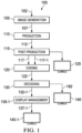
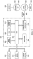
- FIG. 1 depicts an example video/image delivery pipeline 100 showing various stages from video capture to video content display.
- a sequence of video frames 102 is captured or generated using an image generation block 105.
- the video frames (102) may be digitally captured (e.g., by a digital camera, etc.) or generated by a computer (e.g., using computer animation, etc.) to provide video data 107. Additionally, optionally or alternatively, the video frames (102) may be captured on film by a film camera.
- the film can be converted to a digital format to provide the video data (107).
- the film can be converted to a digital format to provide the video data (107). Additionally, optionally or alternatively, some or all of the video frames (102) may be partially or entirely generated by computers using image rendering/generation and/or computer graphics techniques.
- the video data (107) is edited to provide a video production stream 112.
- the video data of the production stream (112) is then provided to a processor for post-production editing 115.
- the post-production editing (115) may include (e.g., automatically, manually, automatically in part manually in part, etc.) adjusting or modifying colors or brightness in particular areas of an image to enhance the image quality or achieve a particular appearance for the image in accordance with the video creator's creative intent.
- color timing This is sometimes called "color timing” or "color grading.”
- Other editing e.g., scene selection and sequencing, manual and/or automatic scene cut information generation, image cropping, addition of computer-generated visual special effects, etc.
- post-production editing may be performed at the post-production editing (115) to yield, through content mapping and/or color grading, an original input video signal 117 (e.g., HDR images, etc.) to a coding block 120 collectively implemented by a plurality of video encoding nodes in a multi-node video encoding system.
- the post-production editing (115) may yield, through content mapping and/or color grading, a reference video signal 117-1 - e.g., SDR images depicting the same visual semantic content as the HDR images in the original input video signal (117-1), etc. - to the coding block (120).
- the reference color grade (117-1) may be derived from the original input video signal through content mapping and/or color grading performed manually, automatically or a combination of manual and automatic image processing operations.
- the original input video signal and/or the reference video signal (117-1) may be used by the coding block (120) or the multi-node coding system - to perform segment-based video encoding and generate an output video signal 122.
- the output video signal (122) may comprise reshaped images the same as or closely approximate (e.g., through minimization of prediction errors, through closed-form solutions to unconstrained or constrained optimization problems, etc.) images in the reference video signal (117-1).
- Example reshaping operations are described in U.S. Patent 10,080,026, "Signal reshaping approximation," by G-M. Su et al. ,
- the original input video signal (117) represents an input color grade of HDR images.
- the reference video signal (117-1) represents a reference color grade of reference images to be approximated by a reshaped color grade represented in the output video signal (122).
- the reference images may be content mapped (e.g., using an appropriate profile of a video encoding tool such as Dolby Vision coding tools commercially available from Dolby Laboratories, Inc., San Francisco, California, etc.) from the HDR images in the original input video signal (117).
- the HDR images in the input video signal (117) are viewed or reviewed on an HDR reference display that supports the high dynamic range by a colorist who is performing post-production editing operations on the HDR images.
- the SDR images in the reference video signal (117-1) are viewed or reviewed on an SDR reference display (e.g., 125 of FIG. 1 , etc.) that supports the standard dynamic range.
- the coding block (120) may implement some or all multi-node segment based video encoding operations as described herein to generate operational parameters for (e.g., forward, backward, etc.) reshaping to map input images in the input video signal to reshaped images and/or to map the reshaped images to reconstructed images approximating the input images.
- the (e.g., forward, etc.) reshaped images can be compressed/encoded by the coding block (120) into the output video signal (122) or a coded bitstream representing the output video signal (122).
- Some or all of the operational parameters for reshaping functions may be included or encoded in the same coded bitstream as a part of image metadata.
- the coding block (120) may include audio and video encoders, such as those defined by ATSC, DVB, DVD, Blu-Ray, and other delivery formats, to generate the coded bitstream (122).
- the output video signal (122) may represent a video signal (e.g., an 8-bit SDR video signal, a 10-bit SDR video signal, etc.) that is backward compatible with a wide variety of SDR display devices (e.g., SDR displays, etc.).
- the video signal encoded with the reshaped SDR images may be a single-layer backward compatible video signal.
- a "single-layer backward compatible video signal” may refer to a video signal that carries SDR images that are specifically optimized or color graded for SDR displays in a single signal layer.
- Example single layer video coding operations are described in U.S. Patent Application Publication No. 2019/0110054, "Encoding and decoding reversible production-quality single-layer video signals," by G-M. Su et al. ,
- the output video signal (122) is then delivered downstream to receivers such as mobile devices, handsets, tablet computers, decoding and playback devices, media source devices, media streaming client devices, television sets (e.g., smart TVs, etc.), set-top boxes, movie theaters, and the like.
- the output video signal (122) is decoded by decoding block (130) to generate decoded images 182, which may be the same as images (e.g., forward reshaped SDR images, etc.) encoded by the coding block (120) into the bitstream (122), subject to quantization errors generated in compression performed by the coding block (120) and decompression performed by the decoding block (130).
- the decoded images represent SDR images that were forward reshaped by an upstream video encoder (e.g., with the coding block (120), etc.) from the color graded HDR images to approximate a reference SDR color grade.
- an upstream video encoder e.g., with the coding block (120), etc.
- the operational parameters for the reshaping functions may be decoded and used in prediction operations by a recipient device of the video signal (122) or coded bitstream to generate reconstructed images of another color grade from the decoded images of one color grade.
- the output video signal (122) or coded bitstream is encoded with additional image metadata including but not limited to display management (DM) metadata that can be used by the downstream decoders to perform display management operations on decoded images or backward reshaped images to generate display images optimized for rendering on target displays, which may or may not have the same display capabilities as reference displays for which the input and reference color grades have been graded.
- DM display management
- the decoding block (130) can decode the images (182) from (e.g., the single layer in, etc.) the coded bitstream (122), and use the decoded images (182) (e.g., forward reshaped SDR images, etc.) directly or indirectly for rendering on the target display (140).
- the decoding block (130) can decode the images (182) from (e.g., the single layer in, etc.) the coded bitstream (122), and use the decoded images (182) (e.g., forward reshaped SDR images, etc.) directly or indirectly for rendering on the target display (140).
- the target display (140) is of similar characteristics as the SDR reference display (125), and the decoded images (182) are forward reshaped SDR images directly watchable on the target display (140).
- the receiver operates with (or is attached or operatively linked to) a target display that has different display capabilities from those of a reference display for which the decoded images (182) were optimized.
- Some or all of the operational parameters for the reshaping functions in the image metadata (or composer metadata) may be used to compose or reconstruct images from the decoded images (182) that are optimized for the target display.
- the receiver may operate with an HDR target display 140-1 that supports a high dynamic range (e.g., 100 nits, 302 nits, 300 nits, 500 nits, 1,000 nits, 4,000 nits, 10,000 nits or more, etc.) than that of the decoded images (182).
- the receiver can extract the image metadata from (e.g., metadata container(s) in, etc.) the coded bitstream representing the output video signal (122), and use the operational parameters for the reshaping functions in the image metadata (or composer metadata) to compose or reconstruct images 132-1 from the decoded images (182) such as forward reshaped SDR images.
- the reconstructed images (132-1) represent reconstructed (e.g., HDR, EDR, images optimized for 1000-nit display devices, images optimized for 4000-nit display devices, etc.) images optimized for viewing on a display that is the same as, or comparable with, a target display operating in conjunction with the receiver.
- the receiver may directly use the reconstructed images (132-1) for rendering on the target display.
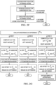
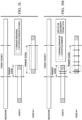
- FIG. 2A illustrates an example process flow for SLBC MADC operations.
- These SLBC MADC operations can be performed by a parallel video encoding system to reduce the bitrate used to transmit image metadata in a SLBC video signal generated by multiple nodes of the video coding system and guarantee or comply with a minimum separation between image metadata updates, while maintaining or keeping temporal consistency among (e.g., all, 99%, etc.) images/frames within a scene, even if the scene is partitioned to be processed by more than one nodes of the video coding system.
- an input video signal (denoted as "Mezzanine”) may be received as input.
- the input video signal may comprise - or may be decoded into - a sequence (e.g., 302 of FIG. 3A , etc.) of (e.g., consecutive, sequential, etc.) images/frames as well as input scene data (denoted as "XML + Auto-SCD").
- the sequence of fixed-length segments may comprise three segments 304-1, 304-2, 304-3, etc. These segments (e.g., 304-1, 304-2, 304-3, etc.) are mutually exclusive, or have no frames in common. Each segment comprises a sub-sequence of (e.g., consecutive, sequential, etc.) images/frames in the sequence (302).
- the three segments e.g., 304-1, 304-2, 304-3, etc.
- Pass-1 or tasks therein mainly focus on generating a list of scenes in a fixed length segment to which the node is assigned.
- Scene cuts from the input scene data provided with the XML file and Automatic Scene Cut Detector (Auto-SCD) can be combined to generate a first list of scenes.
- a scene may be identified - e.g., in a list of scenes - by a scene cut representing a combination of a starting image/frame index and an ending image/frame index in a sequence of consecutive images/frames.
- the last node among the plurality of multiple nodes encodes the images/frames that are in the last fixed length segment.
- the last fixed length segment has only a left (or preceding) bumper section but has no right (or succeeding) bumper section.
- the last fixed length segment may have fewer than L input images/frames.
- Colorist-specified scene cuts can be read in from an XML file. Additionally, optionally or alternatively, an automatic scene cut detector identifies (e.g., possible, candidate, etc.) scene cuts or image/frame locations/indexes delineating the scene cuts.
- an automatic scene cut detector identifies (e.g., possible, candidate, etc.) scene cuts or image/frame locations/indexes delineating the scene cuts.
- Block 204 comprises merging these scene cuts from the colorists and the automatic detector to generate or get a first list of scenes for the segment.
- D opt max D min D avg
- Scenes that are smaller, or have fewer images/frames, than the optimal distance can be merged with the neighboring scenes until the combined scene becomes larger, or has more images/frames, than the optimal distance.
- every primary scene in the segment assigned to the node is larger, or has more input images/frames, than the optimal distance.
- the minimum and average distance constraints are already met then by the primary scenes identified in the updated first list of scenes.
- Block 206 comprises splitting scenes by applying or performing a fixed or variable length scene splitting algorithm/method/process.
- the scene splitting algorithm/method/process may be implemented or performed in a manner that complies with, or intrinsically handles, the minimum distance constraint, but may violate the average distance requirement in the secondary scenes after primary scene splitting.
- MADC operations as described herein can be implemented or performed to prevent this violation even before it happens. These MADC operations can be used or implemented to estimate or establish a worse-case number represented with a maximum number of scenes that may be created in the assigned segment after scene splitting, such that the predicted worst-case number meet the average distance constraint. In operational scenarios in which the worse-case number does not meet or comply with the average distance constraint, a preemptive action may be taken to avoid or prevent such violation.
- Block 208 comprises splitting the primary scenes on the segment boundaries into the secondary scenes (including but not limited to input images/frames in the bumper (frame) section(s)) using fixed-length or variable-length scene splitting techniques, as further adjusted by a possible preemptive action (if applicable).
- the secondary scenes can be added to the updated first list of scenes to generate or get a second list of scenes. This second list can then be provided to tasks in Pass-2 for scene-based encoding.
- the minimum and average distance constraints are already met at this point given the worst-case handling in which a preemptive action can be possibly performed to remedy any possible or potential violation of the average distance constraint.
- scene cuts from a XML file and an automatic scene cut detector can be merged to generate a first list of scenes containing scene cuts. These cuts constitute the first list of scenes.
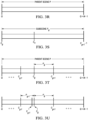
- colorists and professional color graders can manually review a sequence ("Mezzanine") of (e.g., input, consecutive, etc.) images/frames containing a visual depiction of a number of scenes and detect candidate scene cuts (denoted as "XML Scene Cuts” or "XML Scene Cut” in FIG. 3B ) in the sequence.
- ezzanine e.g., input, consecutive, etc.
- the XML scene cuts can be represented and stored in the XML file.
- a dashed vertical line indicates the first frame of a candidate scene represented in the XML file.
- Each node e.g., Node-N, etc.
- the subset of XML scene cuts may comprise XML scene cuts located in a (e.g., video, fixed-length, etc.) segment assigned to the node or in bumper section(s) immediately adjacent to the assigned segment.
- XML scene cuts are detected by the colorists, they may or may not be completely accurate.
- colorists introduce scene cuts in the middle of a dissolving scene or at the start of fade in or fade out portion of a scene. These scene cuts may cause flashing (or false positive) and can be avoided or removed, for example by combining the XML scene cuts with automatic scene cut information - which identifies candidate scene cuts (denoted as "Automatic Scene Cuts” or "Automatic Scene Cut” in FIG. 3C ) for the assigned segment - generated by the automatic scene cut detector (Auto-SCD).
- automatic scene cut information - which identifies candidate scene cuts (denoted as "Automatic Scene Cuts" or "Automatic Scene Cut” in FIG. 3C ) for the assigned segment - generated by the automatic scene cut detector (Auto-SCD).
- the Automatic scene cut detector or Auto-SCD may use changes in luminance or brightness levels in the sequence of images/frames or different subsequences therein to detect a candidate scene change (or cut).
- This automatic detector may be oblivious or agnostic to dissolving, fade in or fade out parts of a video and hence can avoid the false positive problem in connection with the colorists.
- the automatic scene cuts generated by Auto-SCD can also be in the assigned segment or its bumper section(s).
- the automatic detector may have its own false positive problem.
- luminance or brightness changes within a scene due to camera panning, movements, occlusions etc. These luminance or brightness changes may be falsely detected as automatic scene cuts by Auto-SCD.
- the candidate scene cuts from the XML file and Auto-SCD can be merged, for example in block 206 of FIG. 2B .
- ⁇ XML N denote the set of frame indices each of which represents a scene start frame of a respective XML scene cut in a plurality of XML scene cuts (as illustrated in FIG. 3B and FIG. 3D ) in the assigned segment and its bumper section(s) provided to node N (or Node-N), where the subscript indicates that these scene start frames are read from or represented in the XML file.
- Auto ⁇ SCD N denote the set of frame indices each of which represents a scene start frame of a respective automatic scene cut in a plurality of automatic scene cuts (as illustrated in FIG. 3C and FIG. 3D ) in the assigned segment and its bumper section(s) provided to node N (or Node-N), where the subscript indicates that these scene start frames are detected by Auto-SCD.
- ⁇ 1 N ⁇ XML N ⁇ ⁇ Auto ⁇ SCD N
- ⁇ 1 N represents the first list of scene cuts (or scenes; denoted as "Merged Scene Cuts" in FIG. 3D ) for the node N (or Node-N).
- the first list of scenes may contain scene cuts that are closer than the optimal distance. These short scenes may be merged to ensure a scene has more images/frames than the optimal distance. For example, in set ⁇ 1 N , if two neighboring scene cuts are at frames f i and f j , with
- a scene cut removal strategy can be designed, implemented or performed to obtain or achieve consistent results across different neighboring nodes that receives overlapping input images/frames.
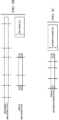
- FIG. 3E illustrates an example first list of scenes ⁇ 1 N in the sequence of input images/frames ("Mezzanine") as well as mandatory scene cuts in two neighboring nodes N and N+1.
- scene cuts derived from the first list of scenes are indicated by dashed vertical lines, whereas mandatory scene cuts occurring at segment boundaries are indicated by solid vertical lines.
- the scene cuts in the common regions ( f NL-B ⁇ f NL+B -1 ) of nodes N and N + 1 are perfectly aligned.
- a simple technique to remove short scene cuts is to traverse the segment and its bumper section(s) from left to right (or alternatively right to left) and remove any scene cut that (e.g., first found to, etc.) violates the optimal distance.
- this simple strategy may not be able to maintain perfect alignment of the resultant scene cuts in the common region for the two neighboring nodes N and N+1.
- FIG. 3F illustrates example scene cuts after removing short scene cuts first encountered in a single traversal direction approach.
- resultant scene cuts in the common regions of nodes N and N + 1 are misaligned. While node N removes both the scene cuts in the common region on both sides of the solid vertical line, node N + 1 removes only one of these two scene cuts on only one side of the solid vertical line.
- temporal inconsistency can be generated in base layer video data of the video signal encoded by the multiple nodes including these two neighboring nodes N and N+1.
- a better approach can be used or implemented to cause a node (e.g., node N) to traverse images/frames in multiple directions as illustrated in FIG. 3G .
- a node e.g., node N
- traversing images/frames by a node - e.g., any of the two neighboring nodes N or N+1 - starts at the same location in the common region and move in the same direction in both nodes.
- the same traversal (process) is replicated or implemented in the two neighboring nodes with respect to the common region.
- input images/frames in the segment and its bumper section(s) provided to the node (node N in the present example) can be partitioned into five portions P1 through P5 with their respective traversal directions as indicated in FIG. 3G .
- P1 represents a preceding bumper section, if any, of the segment.
- P2 represents a first sub-segment (of the assigned segment) overlapping with a trailing bumper section of a previous segment assigned to a previous node (node N-1 in the present example; not shown in FIG. 3G ).
- P3 represents a second sub-segment (of the assigned segment) not overlapping with any input images/frames provided to either the previous node (node N-1) or the subsequent node (node N+1).
- P4 represents a third sub-segment (of the assigned segment) overlapping with a leading (or previous) bumper section of a subsequent segment assigned to the subsequent node (node N+1 in the present example).
- P5 represents a trailing (or subsequent) bumper section, if any, of the segment.
- FIG. 2C illustrates an example process flow for a node (e.g., Node-N, etc.) to traverse input images/frames of a segment assigned to the node and bumper section(s).
- a node e.g., Node-N, etc.
- the traversal starts moving from a mandatory scene cut ( f NL ) at the end of the segment from right to left until reach the first frame ( f NL-B ) in a common region shared between the node and the subsequent node (node N+1 in the present example). Short scenes are merged along the way (whenever first encountered). The same traversal (or path) is followed or replicated by node N + 1.
- the traversal starts moving at the mandatory scene cut ( f NL ) from left to right towards the last frame ( f NL+B -1 ) in the trailing (or right) bumper section.
- the same traversal (or path) is followed or imitated/replicated in node N + 1.
- Similar strategy can be followed by node N in traversing P 1 and P 2, so that these traversals in P1 and P2 by node N mirror or follow the same traversals by node N - 1 in the same overlapping input images/frames of P1 and P2. More specifically, the traversal in P 1 goes from f ( N -1) L to f ( N -1 )L-B , whereas the traversal in P 2 goes from f ( N -1) L to f ( N -1) L+B -1 .
- the traversal P 3 can be made after scene cuts in P 2 and P 4 are completely resolved by the traversals in P 2 and P 4, and can make use of information about the scene cuts in P 2 and P 4.
- the traversal in P3 can go in any direction.
- the traversal in P3 may be (e.g., additionally, alternatively, optionally, etc.) the same as illustrated in FIG.
- Short scenes encountered in the traversals are merged on the way.
- the merging process generates an updated list of scene cuts denoted ⁇ ⁇ 1 N , as illustrated in FIG. 3H .
- the total number of images/frames in the i-th primary scene belonging to this updated list is denoted by F PS i , where F PS i ⁇ D opt ⁇ i in the updated list ⁇ ⁇ 1 N .
- FIG. 3E For the example distribution of scene cuts illustrated in FIG. 3E , primary scenes in the updated list of scene cuts following short scene merging are illustrated in FIG. 3H by applying the multi-directional traversal strategy or process flow as illustrated in FIG. 2C .
- the same scene cuts are removed in the common region of nodes N and N + 1. Alignment of scene cuts is hence preserved across different neighboring nodes and provide temporal stability in scenes that overlap common sections between or among the different neighboring nodes.
- the same scene merging procedure can be followed by each node of the multiple nodes in the multi-node video coding system in the common region.
- the update list of scenes generated by short scene merging from the first list of scenes maintains the optimal distance between any two neighboring scene cuts that separate scenes.
- preemptive measures or actions can be taken by applying fixed length (primary) scene splitting operations to primary scenes on segment boundaries to generate secondary scenes (or subscenes).
- FIG. 3I illustrates example fixed length scene splitting of three primary scenes covering a segment and its bumper sections.
- the maximum allowed number of scenes - exclusive of its bumper sections - in the segment is six (6) for the purpose of complying with the average distance constraint by video encoding operations of the segment by a node in a multi-node encoding system.
- the default secondary subscene length can be increased to F SS ′ for the purpose of reducing the total number of subscenes generated from applying the fixed length scene splitting operations to split primary scenes on the segment boundaries.
- subscenes include anchor subscenes (e.g., subscenes 1 and 8 in FIG. 3I (b) , subscenes 1 and 6 in FIG. 3I (c) , etc.), which may be given a constant length (or total number) of images/frames such as D min .
- anchor subscenes e.g., subscenes 1 and 8 in FIG. 3I (b) , subscenes 1 and 6 in FIG. 3I (c) , etc.
- a worst-case total number of scenes after scene splitting can be estimated and used as a reliable indicator of possible average distance constraint violation.
- FIG. 2D illustrates an example process flow for preemptive measures (or treatment) to avoid average distance constraint violation.
- Preemptive treatment as described herein entails changing the default minimum length of subscene from to some new length F SS ′ . More specifically, the maximum allowed number Z s m of scenes in a segment is computed. The worst-case total number Z s w of scenes in the segment is also estimated or computed with an initial value of the default minimum length of subscene. It is then determined whether the worst-case total number Z s w is no more than the maximum allowed number Z s m .
- the initial value of the default minimum length of subscene is kept or used to split primary scenes on segment boundaries of the segment.
- the default minimum length of subscene is changed from the initial value to a larger value F SS ′ - in place of the initial value of the default minimum length - to split primary scenes on segment boundaries of the segment such that the total number of resultant secondary scenes plus the total number of primary scenes not on any segment boundary in the segment is no more than the maximum allowed number Z s m .
- the process flow may implement a minimum length adjustment algorithm to ingests or receive one or more input parameters and produce a single output as the new minimum length F SS ′ of subscene.
- a primary scene on the left segment boundary of the segment has an index l
- a primary scene on the right segment boundary of the segment has an index r
- Z s r - l + 1 primary scenes in the segment of node N.
- Case 1 (a) the segment is the first segment in a sequence of images/frames processed by multiple nodes of the multi-node video encoding system, and (b) the total number of primary scenes identified by the updated list of scenes in the (first) segment are more than one (1), or Z s > 1.
- anchor subscenes may be used to facilitate or ensure temporal consistency across different segments processed by different nodes. Every primary scene located on a segment boundary may be assigned or provided with one anchor subscene of length D min . For that reason, in expression (4) above, D min is subtracted from the total number of frames in the (last) primary scene, which is then divided by Z P r m ⁇ 1 to account for the anchor subscene in the (last) primary scene.
- a primary scene including the last primary scene here should have more images/frames than both the minimum and average distances.
- Z P r m is at least one. It should be noted that the change in the minimum length/size applies to the segment. Whether any changes are needed or not in any other segments are individually decided for these other segments.
- Case 2 (a) the segment is the last segment in a sequence of images/frames processed by multiple nodes of the multi-node video encoding system, and (b) the total number of primary scenes identified by the updated list of scenes in the (last) segment are more than one (1), or Z s > 1.
- anchor subscenes may be used to facilitate or ensure temporal consistency across different segments processed by different nodes. Every primary scene located on a segment boundary may be assigned or provided with one anchor subscene of length D min . For that reason, in expression (7) above, D min is subtracted from the total number of frames in the (last) primary scene, which is then divided by Z P l m ⁇ 1 to account for the anchor subscene in the (first) primary scene.
- a primary scene including the first primary scene should have more images/frames than both the minimum and average distances.
- Z P l m is at least one.
- This primary scene can be assigned or provided with two anchor subscenes. Adjustments are accordingly made in expression (9) above.
- Case 4 (a) the segment is an interior segment in a sequence of images/frames processed by multiple nodes of the multi-node video encoding system, and (b) the total number of primary scenes identified by the updated list of scenes in the (interior) segment is greater than one (1), or Z s > 1.
- F SS ′ max F P l ⁇ D min Z P l m ⁇ 1 + F P r ⁇ D min Z P r m ⁇ 1 , D min + 1
- Preemptive measures as described herein produce a new default (or minimum) length F SS ′ for secondary scene. Every secondary scene has at least images/frames, except anchor subscenes.
- the new default (or minimum) length ensures compliance with the average distance constraint even in the worst-case scenario.
- FIG. 3J illustrates an example distribution of primary scenes in relation to a segment assigned to a node (e.g., node N, etc.). These primary scenes may be delineated with merged scene cuts after (e.g., short scene, etc.) merging operations. As shown, primary scene 2 is entirely in the segment, and hence can be processed entirely by node N (e.g., with Pass-2 operations of FIG. 2A , etc.). In contrast, primary scenes 1 and 3 are on segment boundaries of the segment. These primary scenes on segment boundaries, which may be referred to as parent scenes, are distributed across multiple nodes and processed by those nodes independently. Special handling may be implemented for primary scenes 1 and 3 to ensure consistent look in boundary images/frames that are encoded by different nodes.
- a node e.g., node N, etc.
- FIG. 3K illustrates an example (simple) scenario in which a parent scene P is distributed across two (adjacent) nodes: node N and N + 1, both of which may have access to only respective parts (or respective subsets or windows of the total number of images/frame) of the parent scene to generate forward reshaping statistics. These respective parts of the parent scene may be referred to as forward reshaping statistics windows, as illustrated in FIG. 3K .
- reshaping parameters are computed on different subsets or windows of images/frames of the parent scene.
- reshaped SDR images encoded in the video signal and reconstructed EDR generated by applying backward reshaping with composer metadata to the reshaped SDR images - at least for the last image/frame ( f ( N+ 1) L -1 ) in the (preceding) segment of node N and the first image/frame ( f ( N +1) L ) in the (subsequent) segment of node N + 1 - may look visually different.
- Such a visual difference can be manifested in the form of flickering, flashing and sudden brightness change, and referred to as temporal inconsistency across different nodes.
- Reasons for such temporal inconsistencies are at least partly due to a lack of common images/frames in the forward reshaping statistics windows or portions of images/frames used by the two adjacent nodes to compute forward reshaping statistics and reshaping parameters.
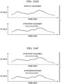
- FIG. 3L illustrates example provision/inclusion of bumper images/frames in forward reshaping statistics windows used by nodes to compute forward reshaping statistics and reshaping parameters.
- These bumper images/frames can be used to compute, generate or complement reshaping statistics used for generating operational parameters of reshaping operations and composer metadata. These operational parameters enable reshaping operations to generate reshaped SDR images and reconstructed HDR images to be implemented or performed with relatively smooth transition across nodes.
- Each of the bumper sections may comprise a small total number of images/frames - as compared with the total number of images/frames in the parent scene - that may not be enough to ensure temporal consistency without additional handling.
- received/provided portions of the parent scene on nodes N and N + 1 can be split into secondary scenes (or subscenes), as illustrated in FIG. 3M .
- secondary scenes or subscenes
- reshaping statistics in a (e.g., parent, primary, etc.) scene may change significantly from start of the scene to end of the scene, reshaping statistics may not change much (e.g., not sufficient to cause perceptible visual artifacts, etc.) from one frame to the next.
- Secondary scenes as described herein represent relatively small neighborhoods (or relatively small sub-portions of consecutive images/frames in the primary scene) from which forward reshaping statistics can be generated for the purpose of evaluating or generating reshaping parameters for forward and backward reshaping. Since the reshaping parameters computed with forward reshaping statistics windows in the subscenes do not change much (e.g., not sufficient to cause perceptible visual artifacts, etc.) from one subscene to the next, scene splitting helps achieve temporal consistency. It should be noted that neighboring subscenes as described herein can be on the previous/next node as well.
- Scene splitting creates additional scenes and increase the bitrate used to transmit composer metadata.
- a goal is to achieve temporal consistency using a minimum number of scene splits to help keep the bitrate for composer metadata bitrate relatively low.
- the minimum and average distance constraints have to be honored complied with after (e.g., finalized, adopted, etc.) scene splitting.
- Bumper images/frames and anchor subscenes can play a relatively significant role in guaranteeing a smooth visual transition from images/frames encoded by a given node to frames encoded by the next node to the given node.
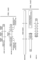
- FIG. 3N illustrates example primary scenes in which anchor subscenes are incorporated to provide or support temporal consistency across different adjacent nodes.
- a parent scene P in a sequence of input images/frames of an input video signal "Mezzanine" spans two or more nodes.
- Anchor subscenes X and Y are assigned or allocated before scene splitting operations commence in the primary scenes on nodes N and N + 1.
- Each of the anchor subscenes has D min images/frames.
- anchor subscene X spans a first frame index range f NL-D min ⁇ f NL -1
- anchor subscene Y spans a second frame index range f NL ⁇ f NL+D min -1 .
- Both anchor subscenes X and Y use all the images/frames in the combined region of anchor subscenes X and Y to compute forward reshaping statistics and composer metadata.
- the combined region spans a combined frame index range f NL-D min ⁇ f NL+D min -1 .
- reshaped base layer has smooth continuity at the segment boundary, even though the images/frames in the first frame index range and the images/frames in the second frame index range are respectively (e.g., independently, without synchronization, etc.) encoded by the two different nodes N and N+1 in isolation.
- primary scene boundaries e.g., the vertical dash lines of FIG. 3N , etc.
- one or both of the anchor subscenes may have more than D min images/frames.
- Short scene merging helps ensure an anchor subscene to have D min or more frames.
- primary scene cuts vertical dotted lines of FIG. 3N
- a mandatory scene cut does exist at start of the segment.
- the anchor subscenes exist on both sides of the right segment boundary (or the mandatory scene cut) of the segment assigned to node N .
- Scene splitting operations can start to be performed after the anchor subscenes are assigned or allocated.
- Scene splitting may include fixed-length scene splitting or variable-length scene splitting.
- Fixed-length scene splitting generates secondary scenes or subscenes with fixed, pre-determined lengths (or fixed, pre-determined total numbers of images/frames). Each subscene has or more images/frames, except for anchors subscenes. Anchor subscenes have D min or more frames in them.
- Variable-length scene splitting can create subscenes with different lengths (or different total numbers of images/frames). Each subscene has or more images/frames, whereas anchor subscenes each have D min or more frames.
- subscenes that have the same length for example as derived in the process flow of FIG. 2D .
- subscenes that are close to the primary scene cuts or anchor scenes may have more than frames.
- anchor subscenes may have D min or more frames.
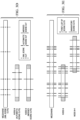
- FIG. 3O , FIG. 3P and FIG. 3Q illustrate example fixed length splitting operations.
- each anchor region comprises two adjacent anchor subscenes anchored or placed on two sides of a segment boundary.
- Each anchor subscene anchored or placed on a side of a segment boundary has a size equal to D min .
- a traversal of a primary scene in a segment is to start moving from an anchor subscene in the primary scene and move away from the anchor subscene toward a scene cut delineating the primary scene, if the anchor subscene is the only anchor subscene in the primary scene. If there are two anchor subscenes in the primary scene, then the traversal can be made from left to right or alternatively from right to left.
- the direction of a traversal is decided depending (e.g., intrinsically, exclusively, independently, etc.) on location(s) of anchor subscene(s) in the primary scene.
- different nodes are enabled to make these decisions (e.g., intrinsically, exclusively, independently, etc.) on their own, in isolation. This greatly facilitate parallel video encoding operations performed by these nodes.
- fixed length splitting operations can start moving from the right anchor subscene (or an anchor subscene anchored or placed on the left side of the right segment boundary; indicated with an arrow underneath in FIG. 3O ) to left towards a scene cut delineating the primary scene in the segment, as illustrated with primary scene P 3 of node X in FIG. 3O .
- fixed length splitting operations can start moving from the left anchor subscene (or an anchor subscene anchored or placed on the right side of the left segment boundary) to right towards a scene cut delineating the primary scene in the segment, as illustrated with primary scene P 1 of node X in FIG. 3O .
- fixed length splitting operations can start moving from the left anchor subscene (or an anchor subscene anchored or placed on the right side of the left segment boundary) to right, as illustrated in primary scene P of node Y in FIG. 3O .
- a parent scene from which primary scenes in segments are derived by segmenting/partitioning may span or at least partly cover three or more nodes.
- the parent scene may span or at least partly cover nodes N-1, N and N+1.
- a first primary scene derived from the parent scene may be a first portion - of the parent scene - in the (N-1)-th segment assigned to node N-1.
- a second primary scene derived from the parent scene may be a second portion - of the parent scene - in the N-th segment assigned to node N.
- a third primary scene derived from the parent scene may be a third portion - of the parent scene - in the (N+1)-th segment assigned to node N+1.
- a traversal of the first primary scene in the (N-1)-th segment assigned to node N-1 can start before the right anchor subscene f ( N -1) L-D min -1 (the anchor subscene anchored or placed on the left side of the right segment boundary of the (N-1)-th segment) and move left towards a left primary scene cut (indicated with a longer vertical dash line) delineating the first primary scene cut.
- a secondary scene cut (indicated with a shorter vertical dashed line) is inserted after every images/frames from right to left, so long as such insertion does not create a subscene with fewer than images/frames.
- the secondary scene bounded by the left primary scene cut delineating the first primary scene may have more than images/frames.
- a traversal of the third primary scene in the (N+1)-th segment assigned to node N+1 can start before the left anchor subscene f ( N+ 1) L+D min (the anchor subscene anchored or placed on the right side of the left segment boundary of the (N+1)-th segment) and move right towards a right primary scene cut (indicated with a longer vertical dash line) delineating the third primary scene cut.
- a secondary scene cut (indicated with a shorter vertical dashed line) is inserted after every images/frames from left to right, so long as such insertion does not create a subscene with fewer than images/frames.
- the secondary scene bounded by the right primary scene cut delineating the third primary scene may have more than images/frames.
- a traversal of the second primary scene in the N-th segment assigned to node N can be from left to right or alternatively right to left.
- the left to right direction of traversal is illustrated in FIG. 3P .
- secondary scene cuts are inserted after every images/frames until the right anchor subscene (of the second primary scene) is reached.
- the subscene just before the right anchor subscene may have more than frames.
- FIG. 3Q illustrates example lengths of subscenes in different primary scenes in different segments assigned to different nodes.
- Minimum lengths , , used to generate subscenes may be different on different nodes.
- a subscene of the minimum length such as one of , , is indicated or pointed to by an arrow.
- a subscenes with no arrow indication or pointing to in a node may be larger than the minimum size of subscene for that node.
- fixed-length scene splitting techniques may be implemented or performed as a default method for scene splitting, and may produce more subscenes than variable-length scene splitting techniques.
- FIG. 2E illustrates an example process flow for variable-length scene splitting operations performed on a parent scene (denoted as scene P ) that is entirely in one node.
- the parent scene equals a primary scene on that node.
- the variable-length scene splitting operations illustrated with such a parent scene can be extended or modified for the purpose of performing variable-length scene splitting on parent scenes each of which may be distributed across two or more nodes.
- scene P comprises M images/frames with the first image/frame (denoted as f Q ) being located at the Q-th frame index in a sequence of consecutive input images/frames in an input video signal ("Mezzanine").
- variable-length scene splitting operations as illustrated in FIG. 2E can be used or performed to split the parent scene into subscenes for temporal consistency. It should be noted that in some operational scenarios, a parent scene that is entirely in a segment assigned to one node may not need to be split, so this example is only for illustration purpose.
- Step A of FIG. 2E comprises accessing SDR and HDR (or EDR) images/frames in the primary scene ( P ) and initializing FLUT, histogram (or HIST), thresholds in connection with the SDR and HDR images/frames in the primary scene ( P ), for example in an initialization phase.
- the SDR and HDR images/frames may comprise a plurality of HDR and SDR image/frame pairs each of which comprises an HDR image and an SDR image depicting the same visual semantic content depicted in the HDR image.
- frame FLUT (denoted as T F or T j F ) and HDR histogram denoted as h v or h j v ) are computed for each (HDR and SDR) image/frame (pair) in scene P , as follows: T j F , h j v ⁇ j ⁇ Q , Q + M ⁇ 1 where j represents the frame index for the (HDR and SDR) image/frame (pair).
- a frame FLUT for a (HDR and SDR) frame/image (pair) represents a mapping of (e.g., input, pre-reshaped, etc.) HDR codewords in the HDR image of the frame/image (pair) to (e.g., forward, etc.) reshaped SDR codewords in a reshaped SDR image approximating the SDR image of the frame/image (pair).
- Elements of a FLUT as described herein can be normalized, e.g., T j F b ⁇ 0.0 , 1.0 .
- Example reshaping operations relating to FLUT are described in PCT Application Ser. No. PCT/US2019/031620, filed on May 9, 2019 ,
- a histogram or bins therein can be set with the same dimension or the same codeword partition as the scene FLUT (or a frame FLUT).
- I j FLUT max ⁇ ⁇ max T j F b ⁇ T j ⁇ 1 F b ⁇ b , ⁇ ⁇ j ⁇ Q + 1 , Q + M ⁇ 1
- ⁇ and ⁇ represent configurable parameters.
- Example values of ⁇ may include, but are not necessarily limited to only, any of 1.8, 1.9, 2.0, 2.1, etc.
- Example values of ⁇ may include, but are not necessarily limited to only, any of 0.004, 0.005, 0.006, etc.
- Thresholds for detecting smoothness violation(s) can be calculated once for all frame indexes j in expression (17) above during the initialization phase in Step A of FIG. 2E and stored in accessible storage or cache for other operations to access.
- Secondary scene cuts denoted as C g can be collected in a sorted set denoted as ⁇ P , where g is an index in the sorted set.
- the frame index, Q + M acts as the end of the list marker in the sorted set and is not used as a (secondary) scene cut.
- the initialization phase implemented in Step A generates the thresholds I j DC and I j FLUT , the violation set Y and the sorted set ⁇ P of secondary scene cuts.
- the subscene P g spans an image/frame range [ C g , C g+ 1 - 1].
- the subscene is not split into two to avoid generating a (new) subscene having fewer than frames.
- the stopping criterion is not met. All the new splits from all the subscenes in the violation set Y are inserted into the sorted set ⁇ P in a corresponding sorted order.
- the sorted set ⁇ P as updated in Step B can then be passed on to the next step, or Step C of FIG. 2E .
- Step C comprises collecting (reshaping related, image content dependent) statistics in all the subscenes identified in the sorted set ⁇ P .
- a subscene FLUT may be computed or established for each secondary scene in the sorted set ⁇ P as updated in Step B.
- ⁇ a DC value in the current round.
- Step D comprises detecting temporal ability violations at subscene edges or boundaries between neighboring/adjacent subscenes.
- FIG. 3U illustrates an example subscene edge (or boundary) C g between subscenes P g -1 and P g .
- Several types of violations can be checked to determine whether any one of those types of violations occurs at the subscene edge (or boundary) C g .
- a violation check (with respect to any of the types of violations) fails, both the subscenes P g -1 and P g are moved or included in the violation set Y.
- the same checks can be applied at each subscene boundary C g , except C 0 , in the parent scene P.
- DC differences can be computed at every secondary scene cut C g , except C 0 , in the sorted ⁇ P .
- Violation Check 1 is performed to determine whether an absolute value
- this violation check is deemed as failed.
- a brightness change at the transition point C g between subscenes P g- 1 and P g represents, or is deemed as, a threshold violation; as a result, these subscenes P g- 1 and P g are appended to the violation set Y to be further split in the next round. Otherwise, this violation check is deemed as passed.
- This criterion or violation check may be a relatively important violation check because of its impact on results of the scene splitting operations.
- Violation Check 2 is performed to determine whether a sign of the DC value difference is the same as a sign of the DC threshold, as follows: sign ⁇ C g ⁇ sign I C g DC
- a positive DC difference ⁇ C g indicates that there is a DC value increase from previous frame to the current (or next) frame following the previous frame. Conversely, a negative DC difference ⁇ C g indicates that there is a DC value decrease the previous frame to the current (or next) frame.
- Violation Check 3 is performed to determine whether a maximum of absolute elementwise difference between FLUTs T P g F and T P g ⁇ 1 F is greater than a threshold I C g FLUT (e.g., as derived based on expression (17) above, etc.) at C g , as follows: max T P g F b ⁇ T P g ⁇ 1 F b ⁇ b > I C g FLUT
- this violation check is deemed as failed (or the smoothness constraint is violated); these subscenes P g -1 and P g are included in or appended to the violation set Y to be further split in the next round. Otherwise, this violation check is deemed as passed (or the smoothness constraint is not violated).
- all the violation checks can be at subscene boundaries. If there is a violation, then both subscenes on both sides of a subscene boundary are appended into the violation set Y to be further split in the next round. The performance of these violation checks ends the scene splitting operations in the current round. If the violation set Y as possibly updated with these violation checks is not empty, the process flow of FIG. 2E goes back to [0182] with the sorted set ⁇ P and the violation set Y for the next round of scene splitting.
- a second stopping criterion (no violations) may be used in Step D of FIG. 2E to determine whether final secondar scene cuts have been obtained. Under this stopping criterion in Step D, in response to determining that no subscene in the parent scene P violates these criteria or violation checks, the stopping criterion is met. Accordingly, the sorted set ⁇ P is outputted as containing the final secondary scene cuts.
- FIG. 2E While the process flow of FIG. 2E is illustrated with a parent scene that is entirely within a segment, it should be noted that, in various embodiments, some or all of these scene splitting techniques can be extended or adjusted for applying to primary scenes on both sides of a segment boundary such as a parent scene shared by (or present in) two or more segments assigned to two or more nodes.
- FIG. 3V illustrates an example parent scene residing on two nodes.
- Each portion of the parent scene in a node (or a corresponding segment) represents a primary scene for that node (or the corresponding segment).
- Three anchor subscene cuts in those two primary scenes delineate two anchor subscenes, which together form an overlap window.
- an anchor scene cut (or split) is introduced at frame f NL-D min
- a second anchor split is introduced at frame f NL+D min .
- a relatively minor change or adjustment can be made in the initialization performed in Step A of the process flow of FIG. 2E for scene splitting a primary scene in a segment by including in the sorted set ⁇ P an additional anchor scene cut in the segment to account for an anchor subscene in the primary scene.
- Step B - for the previous case of a primary scene present only in a single segment - is to split the primary scene in that previous case.
- the process flow can move to Step C directly in the very first round.
- FIG. 3W illustrates an example outcome of variable length scene splitting for the parent scene P of FIG. 3V .
- Variable-length scene splitting may be relatively complicated and computationally intensive as compared with fixed-length scene splitting. However, variable-length scene splitting may bring forth advantages/benefits over fixed-length scene splitting in that a relatively fewer total number of subscenes may be created. In some operational scenarios, fixed-length scene splitting may be used a default in scene splitting.
- FIG. 2F illustrates an example process flow for iterative overlapping to mitigate temporal violations in connection with secondary scenes.
- the process flow receives the sorted set ⁇ P and the violation set Y as input and accesses every subscene in the primary scene P as identified in the violation set Y.
- Step D of FIG. 2E A possibility of temporal inconsistencies at subscene boundaries can be evaluated using some or all the criteria or validation checks in Step D of FIG. 2E .
- Step D of FIG. 2E Following fixed or variable length splitting, in response to determining that no violation is found or detected as per violation checks 1, 2 and 3 in Step D of FIG. 2E at subscene cuts with frame indices ⁇ C 0 , C 1 ⁇ C g ⁇ ⁇ in the sorted set ⁇ P for the primary scene P in a segment assigned to node N, the process flow of FIG. 2F can exit. Otherwise, in response to determining that at least one violation is found or detected at a subscene cut, node N can start the very first iteration of an iterative overlapping process as the current iteration.
- node N access every subscene boundary violation identified in the violation set Y.
- a violation may be found or detected at the frame index C g between the subscenes P g- 1 and P g , as illustrated in FIG. 3U .
- An overlap length for each subscene adjacent to the boundary or subscene cut identified in the violation set Y is initialized to the length of each such subscene.
- the current iteration of the iterative overlapping process comprises (1) determining or checking, for each boundary or subscene cut identified in the violation set Y, whether an adjacent image/frame is available to increase the overlap length of the left (in reference to the boundary or subscene cut) subscene P g- 1 on the right of the left subscene P g- 1 and (2) determining or checking, for that boundary or subscene cut, whether an adjacent image/frame is available to increase the overlap length of the right (in reference to the boundary or subscene cut) subscene P g on the left of the right subscene P g .
- No overlap length for a subscene in the segment assigned to node N can go beyond bumper frames available to node N.
- the overlap length is incremented to include the available adjacent image/frame for the subscene on one or both sides of the boundary or subscene cut ("1. Increase Overlap for Subscenes by One" in FIG. 2F ).
- the overlap length of the right subscene P g is incremented by one (1) on the left
- the overlap length of the left subscene P g- 1 is incremented by one (1) on the right.
- the process flow continues to the next violation in the violation set Y and perform the same overlap length increment operations as described herein.
- the (reshaping related, image content dependent) statistics can be collected for all the subscenes using images/frames in their updated overlap lengths, as illustrated in Step C of FIG. 2E .
- the current iteration of the iterative overlapping process further comprises determining or checking for violations ("3. Check for Violations in Primary Scene" in FIG. 2F ), as illustrated in Step D of FIG. 2E .
- the process flow of FIG. 2F exits ("4. No More Violations” in FIG. 2F ). Otherwise, the process flow of FIG. 2F goes back ("5. Some Violations” in FIG. 2F ) to step 1 ("1. Increase Overlap for Subscenes by One" in FIG. 2F ) of the iterative overlapping process, increments the iteration count, and starts a new iteration as the current iteration.
- a FLUT can be computed for each of these subscenes using a respective overlap length (or window). FLUTs so computed can be stored or cached in data structures to be used in FLUT interpolation. Left and/or right overlap lengths of every subscene can be passed on to the next stage or Pass-2 as a part of auxiliary data.
- a sample parent (or primary) scene with close to 180 frames is divided across three nodes.
- the parent scene is split into fixed length subscenes having 10 frames or more.
- These subscenes may include non-anchor subscene specified with F SS ′ , anchor subscenes, anchor subscenes near primary scene cuts possibly having more than the length specified for an anchor subscene, non-anchor subscenes near primary scene cuts possibly having more than F SS ′ for a non-anchor subscene, etc.
- First absolute DC value differences between neighboring images/frames, when these subscenes are processed separately on the three different nodes in isolation, with iterative overlapping, can be computed.
- second absolute DC value differences between neighboring images/frames when these images/frames are processed on a single node without splitting primary/parent scenes into subscenes and hence without iterative overlapping, can also be computed.
- Iterative overlapping aims to bring the first absolute DC value differences as close as possible to the second absolute DC value differences.
- a peak in the first and second absolute DC value differences corresponds to large DC value differences in neighboring images/frames. Such a peak is a sign of possible temporal inconsistency.
- the total number of iterations in the iterative overlapping may be configurable or preconfigured.
- a hard limit on the total number may be implemented regardless of whether temporal smoothness violations have been completely eliminated in the iterations. This hard limit may be set to a fixed number such as 15, 20, 25, etc., or may be set based on a number of factors: such as segment length (e.g., how many images/frames in a segment, etc.), minimum and average distance constraints, etc.
- FIG. 3Z illustrates example temporal violations as measured or represented with frame (or per-frame) DC values.
- frame DC values e.g., of reshaped base layer images, etc.
- This DC value trend/pattern is considered as normal (e.g., a reference, etc.). Any significant or relatively large deviations from this trend/pattern is an indicator of temporal fluctuations and non-smoothness.
- frame DC values e.g., of reshaped base layer images, etc.
- a primary/parent scene - which is divided into subscenes separately processed, reshaped or encoded using different sets of forward reshaping parameters for subscenes generated from portions of the primary/parent scene - show abrupt DC value changes or many discontinuities. These abrupt DC value changes are seen mainly on the boundaries of the subscenes.
- FLUT interpolation can be implemented to remedy or avoid abrupt DC value changes - in operational scenarios in which subscenes are processed separately by different nodes - for the purpose of providing a better visual experience relatively free of visual artifacts caused by multi-node video encoding.
- FLUT interpolation may be applied after iterative overlapping. Otherwise, FLUT interpolation may be bypassed.
- reshaping parameters can be computed from all images/frames in a statistics collection window of that scene.
- the statistics collection window includes all the images/frames in the primary scene, exclusive of any images/frames outside the primary scenes.
- the statistics collection window includes all images/frames in that secondary scene plus some extra images/frames from one or both of previous and next subscenes. These extra images/frames may be referred to as overlapping images/frames.
- a primary scene does not overlap with any neighboring scene
- a secondary scene is allowed to (e.g., partly, etc.) overlap with neighboring secondary scenes.
- Overlapping images/frames for a subscene does not come from any neighboring primary scene.
- the forward reshaping statistics window for anchor subscene C has no overlapping images/frames on the left from subscene B, but takes all the images/frames from subscene D on the right by way of a trailing bumper section.
- the forward reshaping statistics window for anchor subscene D has no overlapping images/frames on the right from subscene E, but takes all the images/frames from subscene C on the left by way of a leading bumper section.
- the forward reshaping statistics windows for adjacent anchor subscenes C and D are the same.
- same forward and/or backward reshaping parameters can be computed by nodes N and N+1 for the anchor subscenes C and D even if these anchor scenes are (e.g., independently, etc.) encoded in isolation by the two different nodes. This helps achieve a consistent look on neighboring subscenes across nodes.
- each node in a plurality of nodes in a multi-node video encoding system is allocated, or assigned for scene-based video encoding with, a fixed-length segment (except for the last node in the plurality of nodes).
- Images/frames in segments are respectively encoded and (e.g., sequentially, etc.) combined by the plurality of nodes into a video signal such as a set of multiple video segments or an overall coded bitstream.
- Pass-1 operations of MADC operations as illustrated in FIG. 2A generates a (e.g., second, updated first, etc.) list of scenes that can help the video signal reduce the bitrate used to transmit or deliver image metadata in the video signal, while maintaining temporal consistency across different portions of the video signal that are encoded by different (e.g., neighboring, etc.) nodes.
- a e.g., second, updated first, etc.
- the (second) list of scenes may comprise scene cut information that identifies a scene in the segment.
- the node can access SDR images (denoted as "Scene SDR”) and HDR images (denoted as "Scene HDR”) in the scene.
- the auxiliary data may comprise a portion for the secondary scene.
- the node can use the auxiliary data portion for the scene to identify and access extra images/frames in a statistics collection window for the subscene.
- Backward reshaping process is exactly the same for primary and secondary scenes. There is no overlap in the backward reshaping phase.
- a composite bitstream consisting of RPU metadata and compressed base layer is generated as the output. Details of each block are described in the following subsections.
- the forwarding reshaping related operations in the scene-based encoding operations include frame-level forward reshaping statistics collection operation as further illustrated in FIG. 2I and frame-level forward reshaping operation as further illustrated in FIG. 2J .
- a statistics collection window for a subscene may include overlapping images/frames in neighboring subscene(s), whereas a statistics collection window for a primary scene only include images/frames in the primary scene may not include overlapping images/frames.
- information relating to overlapping images/frames for every subscene can be included in and procured from the auxiliary data.
- the image content dependent statistics collected by the frame-level forward reshaping statistics collection operation of FIG. 2H can include statistics for luma (reshaping) as well as statistics for chroma (reshaping), as illustrated in FIG. 2I .
- the statistics collected for luma (reshaping) can be used to generate scene-level FLUT for reshaping luma codewords, as illustrated in FIG. 2J .
- the statistics collected for chroma (reshaping) can be used to generate scene-level MMR mappings for reshaping chroma codewords, as illustrated in FIG. 2J .
- Example MMR based operations are described in U.S. Patent 8,811,490 ,
- the (frame level) forward reshaping may use a scene-level FLUT to forward reshape HDR codewords in each HDR image in a plurality of HDR images of the scene into reshaped SDR codewords in a corresponding reshaped SDR image in a plurality of reshaped SDR images of the scene.
- the statistics of each image/frame (or each image/frame pair) within the (current) scene, as collected for luma (reshaping), can be used to compute optimized forward reshaping coefficients of the scene-level FLUT specifically optimized for the scene.
- Images/frames in this (current) scene may range from frame index S k to S k +1 - 1.
- CDF matching may be used to generate or create a luma forward reshaping mapping function from HDR codewords to SDR codewords.
- Example cumulative density function (CDF) matching operations are described in PCT Application No. PCT/US2017/50980, filed on September 11, 2017 ; U.S. Provisional Application Ser. No. 62/404,307, filed on October 5, 2016 , (also published in Apr. 5, 2018, as U.S. Patent Application Publication Ser. No. 2018/0098094 ).
- T ⁇ F CDF_MATHCING h ⁇ b , h s b
- a (e.g., scene-level, frame-level, etc.) FLUT generated from CDF matching can be altered to remove or prevent clipping artifacts (or visual artifacts generated from clipping).
- the clipping artifacts may be caused by trim operations (e.g., manually, etc.) added by colorists.
- trim correction Operations used to remove or prevent these artifacts may be referred to as trim correction (e.g., luma trim-pass correction as shown in FIG. 2J , etc.), and may be applied to remove or prevent visual artifacts caused by clipping from tone mapping, image editing etc.
- Trim correction operations for primary and secondary scenes are similar, except that, for a secondary scene (or a subscene), trim corrected frame-level FLUTs T j F for images/frames in a statistics collection window of the subscene are averaged to generate a (scene-level or subscene-level) FLUT for the subscene, whereas, for a primary scene, a trim corrected scene-level FLUT is directly used for the primary scene.
- trim correction is performed at frame-level for secondary scenes, whereas trim correction is performed at scene-level for primary scenes.
- Clipping related statistics can be measured or collected in a primary scene or an image/frame of a subscene.
- Example trim-pass correction operations including clipping related statistics are described in U.S. Provisional Patent Application No. 63/089154, "TRIM-PASS CORRECTION FOR CLOUD-BASED CODING OF HDR VIDEO," by HARSHAD KADU et al., filed on 8 October 2020 ;
- a range restricted DM curve (denoted as T ⁇ rr DM ) is constructed or built from a reference (e.g., original unrestricted, etc.) DM curve (denoted as T ⁇ DM ) .
- the refernce DM curve may be specified or defined based on group values of luminance or luma values from the primary scene or the image/frame of the subscene.
- the bounded differential DM curve as given in expression (52) above may be referred to as a range restricted differential DM curve.
- Trim correction can be applied in brightness below the mid point or the midrange of the entire luminance range; in this case, the trim correction may be referred to as low intensity trim correction. Additionally, optionally or alternatively, trim correction can be applied in brightness above the mid point or the midrange of the entire luminance range; in this case, the trim correction may be referred to as high intensity trim correction.
- the CDF and DM curves are merged or combined from v min Y until a merging point determined for the low intensity trim correction.
- the CDF and DM curves are merged or combined from a merging point for the high intensity trim correciton onwards.
- a merging point is an FLUT entry/index value that marks either the end of CDF and DM merging in the low intensity trim correction or the beginning of the CDF and DM merging in the high intensity trim correction.
- An initial estimate of a merging point may be made with respect to an entire SDR codeword range.
- Example operations for estimating merging point(s) are described in the previously mentioned U.S. Provisional Patent Application No. 63/089154 .
- the operations described therein for secondary scenes (or subscenes) of a segment can be likewise performed herein for primary and secondary scenes of a segment.
- Low and high intensity portions of the differential CDF curve can be replaced by corresponding low and high intensity portions of the range restricted differential DM curve to avoid or preventing clipping.
- FIG. 3AI illustrates example DM curve and CDF curve before trim correction (on the left), example range restricted DM curve and range restricted CDF curve range (in the middle), and a trim corrected CDF curve representing an hybrid curve after merging CDF and DM curves.
- the SDR range of the hybrid curve is the same as SDR range of the CDF curve before trim correction.
- the SDR and HDR histograms are computed, followed by CDF matching and trim correction in a primary scene.
- a FLUT can be copied form auxiliary data provided from Pass-1.
- a chroma forward reshaping mapping used to generate forward reshaped chroma codewords may be represented by an MMR-based forward reshaping mapping.
- the MMR-based forward reshaping mapping may be defined or specified with (optimized) operational parameters such as MMR coefficients.
- a three-dimensional mapping table (3DMT) - or more precisely, a dynamic 3DMT (or d3DMT), where "dynamic" means the 3DMT varies from one HDR-SDR image pair to the next - may be constructed from SDR and HDR codewords in the j-th SDR and HDR images/frames in the HDR-SDR image pair in the collection window.
- Example 3DMT or d3DMT construction operations are described in the previously mentioned PCT Application Ser. No. PCT/US2019/031620 .
- chroma trim-pass correction can be performed to update or modify the d3DMT at frame level, for example as described in [1].
- letter box color consistency handling can also be performed to update or modify the d3DMT at frame level, for example as described in the previously mentioned PCT Application Ser. No. PCT/US2019/031620 .
- chroma trim correction and letter box handling are done at the frame-level and results of these operations are already incorporated or contained in a/B matrixes.
- the chroma trim correction can be applied in the same manner to a primary or secondary scene, except that a secondary scene may have extra images/frames as indicated in its overlapping window (or statistics collection window). Some or all information or statistics (e.g., variance, peaks, etc.) obtained from applying luma trim correction may be reused for applying chroma trim correction.
- Optimized forward reshaping functions/mappings generated at scene-level for primary scenes and secondary scenes as identified in the (second) list of scenes can be applied by multiple nodes of the video encoding system to HDR images in a sequence of (e.g., input, consecutive, HDR, etc.) images/frames received with an input video signal to generate corresponding forward reshaped SDR images in a sequence of (e.g., output, consecutive, SDR, etc.) forward reshaped SDR images.
- These reshaped SDR images (not the original SDR images in HDR-SDR image pairs used to generate forward reshaping statistics) can be encoded into (e.g., a base layer of, etc.) an output video signal.
- forward reshaping parameters as generated from the (input, original, etc.) HDR-SDR image pairs can be saved or stored in a binary file of a data store.
- film grain noise can be added or insert into the (e.g., input, original, etc.) HDR images or lumalluminance codewords therein for the purpose of reducing or avoiding banding, false contouring, or compression induced visual artifacts.
- the output video signal encoded with the forward reshaped images may include or carry backward reshaping metadata (or composer metadata) to enable a recipient device of the output video signal to generate reconstructed (e.g., HDR, etc.) images, which approximate the input images that were forward reshaped into the forward reshaped images.
- the backward reshaping metadata may provide scene-level backward reshaping mappings/functions as well as flags/indicators to signal re-using previously transmitted scene-level backward reshaping mappings/functions.
- Backward reshaping mappings/functions may be specified in the composer metadata with (e.g., optimized, etc.) operational parameters such as polynomial coefficients, MMR coefficients, etc. Optimization used to generate the operational parameters (e.g., for backward reshaping, in a backward path, etc.) can be performed at frame-level and/or scene-level in the same manner for a primary or secondary scene.
- a backward reshaping statistics collection operation may be performed to collect backward reshaping statistics for (backward) luma reshaping in a scene.
- a (scene-level) forward luma reshaping function may be represented by a single-channel (e.g., mapping in a single channel of three color channels/components of a color space, mapping in a lumalluminance channel, etc.) predictor, which predicts an output codeword in a single channel from an input codeword in a corresponding single channel.
- the (scene-level) forward luma reshaping function such as a first polynomial can be reverted to obtain a corresponding (scene-level) luma backward reshaping function such as a second polynomial reverted from the first polynomial.
- the backward luma reshaping function may be represented by a backward lookup table or BLUT (denoted as T B ).
- Histogram(s) or histogram bins therein used to generate the BLUT may be used to store backward reshaping statistics collected from input luma (e.g., HDR, input, original, etc.) codewords and forward reshaped luma codewords generated based on the scene-based FLUT made available from the forward path (which implements forward reshaping).
- the BLUT may be constructed from the histogram(s) using a histogram-weighted BLUT construction method/algorithm. Example histogram-weighted BLUT construction operations are described in the previously mentioned PCT Application Ser. No. PCT/US2019/031620 .
- the BLUT may be approximated with a multi-piece polynomial such as an 8-piece second order polynomial.
- Polynomial coefficients specifying the multi-piece polynomial can be used (in place of the BLUT) as a scene-based backward luma reshaping function/mapping (denoted as Scene-based Luma RPU" in FIG. 2K ) as a part of the composer metadata carried in the output video signal.
- the recipient device of the output video signal can perform a backward reshaping operation to apply the BLUT to forward reshaped luma (e.g., SDR) codewords in each encoded (e.g., SDR, etc.) image of the scene to generate corresponding backward reshaped or reconstructed (e.g., HDR, etc.) codewords in a corresponding backward reshaped or reconstructed (e.g., HDR, etc.) image of the scene.
- a backward reshaped luma e.g., SDR
- codewords in each encoded (e.g., SDR, etc.) image of the scene to generate corresponding backward reshaped or reconstructed (e.g., HDR, etc.) codewords in a corresponding backward reshaped or reconstructed (e.g., HDR, etc.) image of the scene.
- the backward reshaping statistics collection operation may also collect backward reshaping statistics for (backward) chroma reshaping in the scene.
- a (scene-level) backward luma reshaping function may be represented by an MMR-based backward reshaping mapping with operational parameters such as MMR coefficients as follows. These operational parameters can be optimized using the collected backward reshaping statistics for (backward) chroma reshaping.
- a d3DMT may be constructed in a manner similar to how a d3DMT is constructed for chroma forward reshaping.
- chroma trim-pass correction may have already been performed in the forward path to ensure reversibility between the forward and backward paths.
- color correction may be performed for letterbox.
- FIG. 4A illustrates an example process flow
- one or more computing devices or components may perform this process flow.
- a multi-node video encoding system having a plurality of video encoding nodes receives a sequence of input images in an input video signal and one or more input lists of scenes as input. The one or more input lists of scenes collectively identify a plurality of primary scenes in the sequence of input images.
- the multi-node system divides the sequence of input images into a plurality of non-overlapping segments.
- Each segment in the plurality of non-overlapping segments is assigned to a respective node in the plurality of video encoding nodes.
- the respective node receives input images within the segment as in-segment images for the segment and input images in one or two bumper sections of the segment as bumper images for the segment.
- the multi-node system uses the plurality of primary scenes identified with the one or more input lists of scenes and segment boundaries delineating neighboring segments in the plurality of non-overlapping segments to generate a second list of scenes to ensure compliance with minimum and average distance constraints.
- the second list of scenes identifies one or more in-segment scenes in the segment.
- the one or more in-segment scenes include zero or more primary scenes not on any segment boundary of the segment and one or more secondary scenes divided from one or more primary scenes on one or both segment boundaries of the segment.
- the multi-node system generates one or more scene-level forward reshaping mappings for the one or more secondary scenes.
- Each scene-level forward reshaping mapping of the one or more scene-level forward reshaping mappings is generated at least in part from reshaping statistics collected from input images in an overlap window determined for a respective secondary scene of the one or more secondary scenes in the segment.
- the multi-node system encodes forward reshaped images in the segment into an output video signal encoded collectively by the plurality of video encoding nodes.
- the output video signal includes an image metadata portion generated by the respective node to enable a recipient device to generate reconstructed images from the forward reshaped images in the segment and to render display images derived from the reconstructed images on an image display.
- the video signal represents a single-layer backward compatible signal.
- the plurality of primary scenes identified by the one or more input lists of scenes are generated by (a) merging manually identified scene cuts in an external list (e.g., XML file, non-XML file or data, etc.) with automatically detected scene cuts by an automatic scene detector into combined scene cuts and (b) merging short scenes represented in the combined scene cuts into longer primary scenes.
- an external list e.g., XML file, non-XML file or data, etc.
- the multi-node system implements fixed length scene splitting that comprises: using an average distance constraint to determine a maximum allowed number of primary and secondary scenes for the segment; using an initial secondary scene length to determine a worst-case number of primary and secondary scenes for the segment; in response to determining that the worst-case number is greater than the maximum allowed number, determining a modified secondary scene length to generate the one or more secondary scenes in the segment.
- the multi-node system implements variable length scene splitting that comprises: (a) generating a sorted set of candidate secondary scene cuts in the segment and a violation set and a violation set identifying candidate secondary scenes, in the sorted set of candidate scene cuts, with smoothness violations; (b) splitting the candidate secondary scenes in the violation set into additional candidate secondary scenes to be updated into the sorted list of candidate secondary scene cuts; (c) updating the violation sets to include additional candidate secondary scenes, in the updated sorted list of candidate secondary scene cuts, with the smoothness violations; (d) in response to determining that one or more stopping criteria are not met, repeating (a) through (d) with the updated sorted list of candidate secondary scene cuts and the updated violation set, until at least one of the one or more stopping criteria is met.
- the one or more scene-level forward reshaping mappings are adjusted with one or more of: forward reshaping mapping interpolations between adjacent secondary scenes, offsets, etc.
- the zero or more primary scenes and the one or more secondary scenes comprise a specific scene with an overlap window; the overlap window cover multiple image pairs formed by multiple standard dynamic range (SDR) images and multiple high dynamic range (HDR) images; the multi-node system further performs: generating multiple SDR histograms from luma SDR codewords in the multiple SDR images covered by the overlap window of the specific scene; generating multiple HDR histograms from luma HDR codewords in the multiple HDR images covered by the overlap window of the specific scene; generating a scene-level SDR histogram by averaging the multiple SDR histograms and a scene-level HDR histogram by averaging the multiple HDR histograms; applying CDF matching to the scene-level SDR histogram and the scene-level HDR histogram to generate a CDF matched luma forward reshaping function; applying luma trim correction to the CDF matched luma forward reshaping function to generate a scene-level
- the zero or more primary scenes and the one or more secondary scenes comprise a specific scene with an overlap window; the overlap window cover multiple image pairs formed by multiple standard dynamic range (SDR) images and multiple high dynamic range (HDR) images; the multi-node system further performs: generating multiple frame-level three-dimensional mapping tables (3dMTs) from SDR codewords in the multiple SDR images covered by the overlap window of the specific scene and from HDR codewords in the multiple HDR images covered by the overlap window of the specific scene; applying trim correction and letterbox handling to the multiple frame-level 3dMTs to generate multiple trim-corrected 3dMTs; using the multiple trim-corrected 3dMTs to derive frame-level a/B matrixes for the multiple image pairs; generating scene-level a/B matrixes from the frame-level a/B matrixes; generating optimized multiple color channel multiple regression (MMR) coefficients by solving an optimization problem formulated with the scene-level a/B matrixes.
- 3dMTs multiple frame-level three
- each segment boundary of the segment serves as a scene cut for a scene in the second list of scenes.
- the segment comprises at least one of: a primary scene entirely inside the segment, a subscene derived from a portion of a parent scene representing a primary scene identified in the list of primary scenes, an anchor subscene adjacent to a segment boundary of the segment, a non-anchor subscene not adjacent to any segment boundary of the segment, etc.
- the segment is adjacent to a second segment in the plurality of segments; the second segment is assigned to a second different node in the plurality of video encoding nodes for video encoding; the segment and the second segment share a common anchor subscene overlap window formed by an anchor segment in the segment and a second anchor segment in the second segment.
- the sequence of input images represents a sequence of high dynamic range (HDR) images; the forward reshaped images encoded in the video signal represent standard dynamic range (SDR) images.
- HDR high dynamic range
- SDR standard dynamic range
- FIG. 4B illustrates an example process flow according to an embodiment.
- one or more computing devices or components may perform this process flow.
- an image processing system decodes a sequence of forward reshaped images from a video signal.
- the video signal has been generated by a plurality of video encoding nodes in a multi-node video encoding system.
- the video signal includes image metadata generated by the plurality of video encoding nodes.
- the sequence of forward reshaped images includes forward reshaped images encoded into the video signal by a node in the plurality of video encoding nodes for a segment in a plurality of segments used to partition a sequence of source images.
- the sequence of forward reshaped images includes a segment of forward reshaped images that was generated by a node of the multi-node video encoding system using forward reshaping functions for one or more scenes identified in a segment of pre-reshaped source images.
- the one or more scenes identified in the segment of pre-reshaped source images were ensured by the node to be in compliance with minimum and average distance constraints.
- the image processing system uses an image metadata portion in the image metadata to generate reconstructed images from the forward reshaped images in the segment.
- the image metadata portion has been generated by the node.
- the image processing system renders display images derived from the reconstructed images on an image display.
- a computing device such as a display device, a mobile device, a set-top box, a multimedia device, etc.
- an apparatus comprises a processor and is configured to perform any of the foregoing methods.
- a non-transitory computer readable storage medium storing software instructions, which when executed by one or more processors cause performance of any of the foregoing methods.
- a computing device comprising one or more processors and one or more storage media storing a set of instructions which, when executed by the one or more processors, cause performance of any of the foregoing methods.
- Embodiments of the present invention may be implemented with a computer system, systems configured in electronic circuitry and components, an integrated circuit (IC) device such as a microcontroller, a field programmable gate array (FPGA), or another configurable or programmable logic device (PLD), a discrete time or digital signal processor (DSP), an application specific IC (ASIC), and/or apparatus that includes one or more of such systems, devices or components.
- IC integrated circuit
- FPGA field programmable gate array
- PLD configurable or programmable logic device
- DSP discrete time or digital signal processor
- ASIC application specific IC
- the computer and/or IC may perform, control, or execute instructions relating to the adaptive perceptual quantization of images with enhanced dynamic range, such as those described herein.
- the computer and/or IC may compute any of a variety of parameters or values that relate to the adaptive perceptual quantization processes described herein.
- the image and video embodiments may be implemented in hardware, software, firmware and various combinations thereof.
- Certain implementations of the inventio comprise computer processors which execute software instructions which cause the processors to perform a method of the disclosure.
- one or more processors in a display, an encoder, a set top box, a transcoder or the like may implement methods related to adaptive perceptual quantization of HDR images as described above by executing software instructions in a program memory accessible to the processors.
- Embodiments of the invention may also be provided in the form of a program product.
- the program product may comprise any non-transitory medium which carries a set of computer-readable signals comprising instructions which, when executed by a data processor, cause the data processor to execute a method of an embodiment of the invention.
- Program products according to embodiments of the invention may be in any of a wide variety of forms.
- the program product may comprise, for example, physical media such as magnetic data storage media including floppy diskettes, hard disk drives, optical data storage media including CD ROMs, DVDs, electronic data storage media including ROMs, flash RAM, or the like.
- the computer-readable signals on the program product may optionally be compressed or encrypted.
- a component e.g. a software module, processor, assembly, device, circuit, etc.
- reference to that component should be interpreted as including as equivalents of that component any component which performs the function of the described component (e.g., that is functionally equivalent), including components which are not structurally equivalent to the disclosed structure which performs the function in the illustrated example embodiments of the invention.
- the techniques described herein are implemented by one or more special-purpose computing devices.
- the special-purpose computing devices may be hard-wired to perform the techniques, or may include digital electronic devices such as one or more application-specific integrated circuits (ASICs) or field programmable gate arrays (FPGAs) that are persistently programmed to perform the techniques, or may include one or more general purpose hardware processors programmed to perform the techniques pursuant to program instructions in firmware, memory, other storage, or a combination.
- ASICs application-specific integrated circuits
- FPGAs field programmable gate arrays
- Such special-purpose computing devices may also combine custom hard-wired logic, ASICs, or FPGAs with custom programming to accomplish the techniques.
- the special-purpose computing devices may be desktop computer systems, portable computer systems, handheld devices, networking devices or any other device that incorporates hard-wired and/or program logic to implement the techniques.
- FIG. 5 is a block diagram that illustrates a computer system 500 upon which an embodiment of the invention may be implemented.
- Computer system 500 includes a bus 502 or other communication mechanism for communicating information, and a hardware processor 504 coupled with bus 502 for processing information.
- Hardware processor 504 may be, for example, a general purpose microprocessor.
- Computer system 500 also includes a main memory 506, such as a random access memory (RAM) or other dynamic storage device, coupled to bus 502 for storing information and instructions to be executed by processor 504.
- Main memory 506 also may be used for storing temporary variables or other intermediate information during execution of instructions to be executed by processor 504.
- Such instructions when stored in non-transitory storage media accessible to processor 504, render computer system 500 into a special-purpose machine that is customized to perform the operations specified in the instructions.
- Computer system 500 further includes a read only memory (ROM) 508 or other static storage device coupled to bus 502 for storing static information and instructions for processor 504.
- ROM read only memory
- a storage device 510 such as a magnetic disk or optical disk, is provided and coupled to bus 502 for storing information and instructions.
- Computer system 500 may be coupled via bus 502 to a display 512, such as a liquid crystal display, for displaying information to a computer user.
- a display 512 such as a liquid crystal display
- An input device 514 is coupled to bus 502 for communicating information and command selections to processor 504.
- cursor control 516 is Another type of user input device
- cursor control 516 such as a mouse, a trackball, or cursor direction keys for communicating direction information and command selections to processor 504 and for controlling cursor movement on display 512.
- This input device typically has two degrees of freedom in two axes, a first axis (e.g., x) and a second axis (e.g., y), that allows the device to specify positions in a plane.
- Computer system 500 may implement the techniques described herein using customized hard-wired logic, one or more ASICs or FPGAs, firmware and/or program logic which in combination with the computer system causes or programs computer system 500 to be a special-purpose machine. According to one embodiment, the techniques as described herein are performed by computer system 500 in response to processor 504 executing one or more sequences of one or more instructions contained in main memory 506. Such instructions may be read into main memory 506 from another storage medium, such as storage device 510. Execution of the sequences of instructions contained in main memory 506 causes processor 504 to perform the process steps described herein. In alternative embodiments, hard-wired circuitry may be used in place of or in combination with software instructions.
- Non-volatile media includes, for example, optical or magnetic disks, such as storage device 510.
- Volatile media includes dynamic memory, such as main memory 506.
- Common forms of storage media include, for example, a floppy disk, a flexible disk, hard disk, solid state drive, magnetic tape, or any other magnetic data storage medium, a CD-ROM, any other optical data storage medium, any physical medium with patterns of holes, a RAM, a PROM, and EPROM, a FLASH-EPROM, NVRAM, any other memory chip or cartridge.
- Storage media is distinct from but may be used in conjunction with transmission media.
- Transmission media participates in transferring information between storage media.
- transmission media includes coaxial cables, copper wire and fiber optics, including the wires that comprise bus 502.
- transmission media can also take the form of acoustic or light waves, such as those generated during radio-wave and infra-red data communications.
- Various forms of media may be involved in carrying one or more sequences of one or more instructions to processor 504 for execution.
- the instructions may initially be carried on a magnetic disk or solid state drive of a remote computer.
- the remote computer can load the instructions into its dynamic memory and send the instructions over a telephone line using a modem.
- a modem local to computer system 500 can receive the data on the telephone line and use an infra-red transmitter to convert the data to an infra-red signal.
- An infra-red detector can receive the data carried in the infra-red signal and appropriate circuitry can place the data on bus 502.
- Bus 502 carries the data to main memory 506, from which processor 504 retrieves and executes the instructions.
- the instructions received by main memory 506 may optionally be stored on storage device 510 either before or after execution by processor 504.
- Computer system 500 also includes a communication interface 518 coupled to bus 502.
- Communication interface 518 provides a two-way data communication coupling to a network link 520 that is connected to a local network 522.
- communication interface 518 may be an integrated services digital network (ISDN) card, cable modem, satellite modem, or a modem to provide a data communication connection to a corresponding type of telephone line.
- ISDN integrated services digital network
- communication interface 518 may be a local area network (LAN) card to provide a data communication connection to a compatible LAN.
- LAN local area network
- Wireless links may also be implemented.
- communication interface 518 sends and receives electrical, electromagnetic or optical signals that carry digital data streams representing various types of information.
- Network link 520 typically provides data communication through one or more networks to other data devices.
- network link 520 may provide a connection through local network 522 to a host computer 524 or to data equipment operated by an Internet Service Provider (ISP) 526.
- ISP 526 in turn provides data communication services through the world wide packet data communication network now commonly referred to as the "Internet" 528.
- Internet 528 uses electrical, electromagnetic or optical signals that carry digital data streams.
- the signals through the various networks and the signals on network link 520 and through communication interface 518, which carry the digital data to and from computer system 500, are example forms of transmission media.
- Computer system 500 can send messages and receive data, including program code, through the network(s), network link 520 and communication interface 518.
- a server 530 might transmit a requested code for an application program through Internet 528, ISP 526, local network 522 and communication interface 518.
- the received code may be executed by processor 504 as it is received, and/or stored in storage device 510, or other non-volatile storage for later execution.
Landscapes
- Engineering & Computer Science (AREA)
- Multimedia (AREA)
- Signal Processing (AREA)
- Compression Or Coding Systems Of Tv Signals (AREA)
Claims (11)
- Verfahren, umfassend:Empfangen einer Sequenz von Eingabebildern in einem Eingabevideosignal und einer oder mehrerer Eingabelisten von Szenen als Eingabe für ein Mehrknoten-Videokodierungssystem, das eine Vielzahl von Videokodierungsknoten aufweist, wobei die eine oder mehrere Eingabelisten von Szenen gemeinsam eine Vielzahl von Primärszenen in der Sequenz von Eingabebildern identifizieren, wobei jede der Vielzahl von Primärszenen, die durch die eine oder mehrere Eingabelisten von Szenen identifiziert werden, erzeugt wird durch (a) Zusammenführen manuell identifizierter Szenenschnitte in einer externen Liste mit automatisch erkannten Szenenschnitten durch einen automatischen Szenendetektor zu kombinierten Szenenschnitten benachbarter Szenen oder durch (b) Zusammenführen von in den kombinierten Szenenschnitten dargestellten benachbarten Szenen zu längeren Primärszenen, wobei benachbarte Szenen zusammengeführt werden, bis die Länge der kombinierten Szene einen Schwellenwert überschreitet, der einen vorgegebenen Durchschnittsabstand zur nächsten Nachbarszene darstellt, so dass jede kombinierte Szene eine Durchschnittsabstandsbeschränkung erfüllt;Aufteilen der Sequenz von Eingabebildern in eine Vielzahl von sich nicht überlappenden Segmenten, wobei jedes Segment in der Vielzahl von sich nicht überlappenden Segmenten einem entsprechenden Knoten in der Vielzahl von Videokodierungsknoten zugewiesen wird und der entsprechende Knoten Eingabebilder innerhalb des jeweiligen Segments als segmentinterne Bilder für das Segment und Eingabebilder in einem oder zwei Bumper-Teilabschnitten des jeweiligen Segments empfängt, wobei jeder Bumper-Teilabschnitt eine Anzahl von Bildern umfasst, die vor dem ersten Bild des jeweiligen Segments kommen oder dem letzten Bild des jeweiligen Segments folgen;Erzeugen einer zweiten Liste von Szenen aus der Vielzahl von Primärszenen in der Sequenz von Eingabebildern, wobei die zweite Liste von Szenen eine oder mehrere der Vielzahl von Primärszenen als segmentintere Szenen im jeweiligen Segment identifiziert, wobei die eine oder mehreren Segmentszenen null oder mehr Primärszenen beinhalten, die sich nicht auf einer Segmentgrenze des jeweiligen Segments befinden, und eine oder mehrere Sekundärszenen, die von einer oder mehreren Primärszenen an einer oder beiden Segmentgrenzen des jeweiligen Segments abgetrennt sind, wobei die Sekundärszenen die Bilder des Bumper-Teilabschnitts an der jeweiligen Segmentgrenze umfassen, wobei jede Sekundärszene, ausschließlich ihrer Bumper-Teilabschnitte, eine Länge aufweist, die größer oder gleich einem vorgegebenen Mindestabstand zur nächsten Nachbarszene ist, wodurch jede Sekundärszene eine Mindestabstandsbeschränkung erfüllt, wobei der vorgegebene Mindestabstand kleiner als der vorgegebene Durchschnittsabstand ist, und wobei die Durchschnittslänge der Szenen in der zweiten Liste von Szenen, ausschließlich ihrer Bumper-Teilabschnitte, größer als oder gleich dem vorgegebenen Durchschnittsabstand zur nächsten Nachbarszene ist, wodurch die Szenen in der zweiten Liste von Szenen die Durchschnittsabstandsbeschränkung erfüllen;Erzeugen einer Vorwärts-Umformungszuordnung auf Szenenebene für jede Szene der zweiten Liste von Szenen im jeweiligen Segment, wobei die Vorwärts-Umformungszuordnung auf Szenenebene Eingabebilder auf entsprechende vorwärts umgeformte Bilder abbilden kann, die einen Standarddynamikbereich (SDR) aufweisen, der kleiner ist als ein hoher Dynamikbereich (HDR) der Eingabebilder, wobei jede Vorwärts-Umformungszuordnung auf Szenenebene zumindest teilweise aus Umformungsstatistiken erzeugt wird, die aus Eingabebildern in einem Überlappungsfenster gesammelt werden, das für eine jeweilige Szene der zweiten Liste von Szenen im jeweiligen Segment beinhaltend seiner Bumper-Teilabschnitte bestimmt wurde, wobei die Umformungsstatistiken Statistiken aus (i) Luma-Codewörtern in einer SDR-Version jedes Eingabebildes im Überlappungsfenster, aggregiert zu einem SDR-Histogramm auf Szenenebene, und (ii) Luma-Codewörtern in jedem Eingabebild im Überlappungsfenster, aggregiert zu einem HDR-Histogramm auf Szenenebene, umfassen;Anwenden der erzeugten Vorwärtsumformungszuordnungen auf Szenenebene durch den jeweiligen Knoten auf die Eingabebilder der Szenen der zweiten Liste von Szenen für das jeweilige Segment ausschließlich seiner Bumper-Teilabschnitte, um vorwärtsumgeformte Bilder des jeweiligen Segments zu erzeugen;Kodieren der vorwärts umgeformten Bilder im jeweiligen Segment durch den jeweiligen Knoten in ein Ausgabevideosignal, das gemeinsam durch die Vielzahl von Videokodierungsknoten kodiert wird, wobei das Ausgabevideosignal einen Bildmetadatenabschnitt beinhaltet, der durch den jeweiligen Knoten erzeugt wird, um einer Empfängervorrichtung Erzeugen von rekonstruierten Bildern aus den vorwärts umgeformten Bildern im jeweiligen Segment und Rendern von Anzeigebildern, die aus den rekonstruierten Bildern abgeleitet wurden, auf einer Bildanzeige zu ermöglichen, wobei derselbe Bildmetadatenabschnitt für alle Bilder einer kodierten Szene verwendet wird, sodass der Bildmetadatenabschnitt die Mindestabstandsbeschränkung und die Durchschnittsabstandsbeschränkung erfüllt.
- Verfahren nach Anspruch 1, wobei der Bildmetadatenabschnitt Rückwärts-Umformungsparameter beinhaltet, die für die eine oder mehrere Sekundärszenen erzeugt wurden; wobei die Rückwärts-Umformungsparameter von der Empfängervorrichtung verwendet werden, um die rekonstruierten Bilder zumindest teilweise durch Rückwärts-Umformung der vorwärts umgeformten Bilder unter Verwendung der Rückwärts-Umformungsparameter zu erzeugen.
- Verfahren nach Anspruch 1 oder 2, wobei das Ausgabevideosignal ein einschichtiges, rückwärtskompatibles Videosignal darstellt, das SDR-Bilder überträgt, die für SDR-Anzeigen in einer einzigen Signalschicht optimiert oder farblich abgestuft sind.
- Verfahren nach einem der Ansprüche 1-3, wobei das Verfahren eine Szenenaufteilung mit fester Länge der jeweiligen Szene implementiert, die Folgendes umfasst:Verwenden einer Durchschnittsabstandsbeschränkung, um eine maximal zulässige Anzahl von Primär- und Sekundärszenen für das Segment zu bestimmen;Verwenden einer anfänglichen Sekundärszenenlänge, um eine Worst-Case-Anzahl von Primär- und Sekundärszenen für das Segment zu bestimmen;als Reaktion auf Bestimmen, dass die Worst-Case-Zahl größer als die maximal zulässige Zahl ist, Bestimmen einer geänderten Sekundärszenenlänge zum Erzeugen der einen oder mehreren Sekundärszenen im Segment.
- Verfahren nach einem der Ansprüche 1-4, wobei das Verfahren eine Szenenaufteilung mit variabler Länge der jeweiligen Szene implementiert, die Folgendes umfasst:(a) Erzeugen eines sortierten Satzes von Kandidaten für Sekundärszenenschnitte im jeweiligen Segment und eines Verletzungssatzes, der Kandidaten für Sekundärszenen mit Glätteverletzungen in dem sortierten Satz von Kandidaten für Szenenschnitte identifiziert, wobei die Kandidaten für Sekundärszenenschnitte in aufsteigender Reihenfolge entsprechend ihrer Bildposition sortiert sind und eine Glätteverletzung eine DC-Wertdifferenz zwischen zwei benachbarten Bildern darstellt, die einen Schwellenwert für die Entscheidung über die Szenenaufteilung überschreitet;(b) Aufteilen der Kandidaten für Sekundärszenen in dem Verletzungssatz in weitere Kandidaten für Sekundärszenen, die in dem sortierten Satz von Kandidaten für Sekundärszenenschnitte zu aktualisieren sind;(c) Aktualisieren der Verletzungssätze, um zusätzliche Kandidaten für Sekundärszenen in dem aktualisierten sortierten Satz von Kandidaten für Sekundärszenenschnitte mit den Glätteverletzungen zu beinhalten;(d) als Reaktion auf Bestimmen, dass ein oder mehrere Abbruchkriterien nicht erfüllt sind, Wiederholen von (a) bis (d) mit dem aktualisierten sortierten Satz von Kandidaten für Sekundärszenenschnitte und dem aktualisierten Verletzungssatz, bis zumindest eines der einen oder mehreren Abbruchkriterien erfüllt ist, wobei die einen oder mehreren Abbruchkriterien zumindest eines von keinen neuen Aufteilungen und keinen Verletzungssätzen umfassen.
- Verfahren nach einem der Ansprüche 1-5, wobei die eine oder mehrere VorwärtsUmformungszuordnungen auf Szenenebene mit einem oder mehreren der Folgenden angepasst werden: Vorwärts-Umformungszuordnungsinterpolationen zwischen benachbarten Sekundärszenen oder Offsets.
- Verfahren nach einem der Ansprüche 1-6, wobei das jeweilige Segment zumindest eines der Folgenden umfasst: eine Primärszene, die vollständig innerhalb des jeweiligen Segments liegt, eine Unterszene, die aus einem Abschnitt einer übergeordneten Szene abgeleitet ist, die eine in der Liste von Primärszenen identifizierte Primärszene darstellt, eine Anker-Unterszene neben einer Segmentgrenze des jeweiligen Segments oder eine Nicht-Anker-Unterszene, die an keine Segmentgrenze des jeweiligen Segments angrenzt, wobei eine Anker-Unterszene eine Sekundärszene ist, die von einer Primärszene an einer Segmentgrenze getrennt ist, welche die Mindestabstandsbeschränkung erfüllt, wobei die Anker-Unterszene zeitliche Konsistenz über verschiedene Segmente hinweg sicherstellt, die von verschiedenen Knoten verarbeitet werden.
- Verfahren nach einem der Ansprüche 1-7, wobei das jeweilige Segment an ein jeweiliges zweites Segment in der Vielzahl von Segmenten angrenzt; wobei das jeweilige zweite Segment einem zweiten anderen Knoten in der Vielzahl von Videokodierungsknoten zur Videokodierung zugewiesen ist; wobei das jeweilige Segment und das jeweilige zweite Segment ein gemeinsames Anker-Unterszenen-Überlappungsfenster teilen, das durch ein Anker-Segment in dem jeweiligen Segment und ein zweites Anker-Segment in dem jeweiligen zweiten Segment gebildet wird.
- Verfahren, umfassend:Dekodieren einer Sequenz vorwärts umgeformter Bilder aus einem Videosignal, wobei das Videosignal von einer Vielzahl von Videokodierungsknoten in einem Mehrknoten-Videokodiersystem gemäß dem Verfahren nach einem der Ansprüche 1-8 erzeugt wurde, wobei das Videosignal von der Vielzahl von Videokodierungsknoten erzeugte Bildmetadaten beinhaltet, wobei die Sequenz vorwärts umgeformter Bilder vorwärts umgeformte Bilder beinhaltet, die von einem Knoten der Vielzahl von Videokodierungsknoten für ein Segment in einer Vielzahl von Segmenten, die zum Unterteilen einer Sequenz von Quellbildern verwendet werden, in das Videosignal kodiert wurden;wobei die Sequenz vorwärts umgeformter Bilder ein Segment vorwärts umgeformter Bilder beinhaltet, das von einem Knoten des Mehrknoten-Videokodierungssystems unter Verwendung von Vorwärtsumformungsfunktionen für eine oder mehrere Szenen erzeugt wurde, die in einem Segment vorumgeformter Quellbilder identifiziert wurden, wobei der Knoten sichergestellt hat, dass die eine oder mehreren Szenen, die in dem Segment vorumgeformter Quellbilder identifiziert wurden, den Mindest- und Durchschnittsabstandsbeschränkungen entsprechen;Verwenden eines Bildmetadatenabschnitts in den Bildmetadaten, um rekonstruierte Bilder aus den vorwärts umgeformten Bildern im Segment zu erzeugen, wobei der Bildmetadatenabschnitt vom Knoten erzeugt wurde;Rendern von aus den rekonstruierten Bildern abgeleiteten Anzeigebildern auf einer Bildanzeige.
- Einrichtung, die einen Prozessor umfasst und zum Durchführen eines beliebigen der Verfahren nach einem der Ansprüche 1-9 ausgelegt ist.
- Nichtflüchtiges computerlesbares Speichermedium, das darauf gespeicherte computerausführbare Anweisung zum Ausführen eines Verfahrens mit einem oder mehreren Prozessoren in Übereinstimmung mit einem beliebigen der Verfahren nach den Ansprüchen 1-9 gespeichert sind.
Applications Claiming Priority (3)
| Application Number | Priority Date | Filing Date | Title |
|---|---|---|---|
| US202163233458P | 2021-08-16 | 2021-08-16 | |
| EP21191429 | 2021-08-16 | ||
| PCT/US2022/040282 WO2023022956A1 (en) | 2021-08-16 | 2022-08-14 | Applying minimum and average distance constraint in video streaming |
Publications (2)
| Publication Number | Publication Date |
|---|---|
| EP4388740A1 EP4388740A1 (de) | 2024-06-26 |
| EP4388740B1 true EP4388740B1 (de) | 2025-02-26 |
Family
ID=83115407
Family Applications (1)
| Application Number | Title | Priority Date | Filing Date |
|---|---|---|---|
| EP22761334.6A Active EP4388740B1 (de) | 2021-08-16 | 2022-08-14 | Anwendung der mindest- und durchschnittsentfernungsbeschränkung beim videostreaming |
Country Status (4)
| Country | Link |
|---|---|
| US (1) | US12143644B1 (de) |
| EP (1) | EP4388740B1 (de) |
| JP (1) | JP7602694B2 (de) |
| WO (1) | WO2023022956A1 (de) |
Families Citing this family (1)
| Publication number | Priority date | Publication date | Assignee | Title |
|---|---|---|---|---|
| CN116195248A (zh) | 2020-09-18 | 2023-05-30 | 杜比实验室特许公司 | 用于hdr视频的基于云的编码的递归段到场景分段 |
Citations (1)
| Publication number | Priority date | Publication date | Assignee | Title |
|---|---|---|---|---|
| EP3510772B1 (de) * | 2016-09-09 | 2020-12-09 | Dolby Laboratories Licensing Corporation | Codierung von video mit hohem dynamikbereich mittels segmentbasierter neuformung |
Family Cites Families (17)
| Publication number | Priority date | Publication date | Assignee | Title |
|---|---|---|---|---|
| HUE046186T2 (hu) | 2011-04-14 | 2020-02-28 | Dolby Laboratories Licensing Corp | Több színcsatornás több regressziós prediktor |
| US11128935B2 (en) * | 2012-06-26 | 2021-09-21 | BTS Software Solutions, LLC | Realtime multimodel lossless data compression system and method |
| KR101844732B1 (ko) | 2015-03-20 | 2018-04-02 | 돌비 레버러토리즈 라이쎈싱 코오포레이션 | 신호 재정형 근사화 |
| CN108885783B (zh) | 2016-03-23 | 2022-02-15 | 杜比实验室特许公司 | 编码和解码可逆制作质量单层视频信号 |
| GB201611253D0 (en) | 2016-06-29 | 2016-08-10 | Dolby Laboratories Licensing Corp | Efficient Histogram-based luma look matching |
| WO2018049335A1 (en) | 2016-09-09 | 2018-03-15 | Dolby Laboratories Licensing Corporation | Coding of high dynamic range video using segment-based reshaping |
| US10264287B2 (en) | 2016-10-05 | 2019-04-16 | Dolby Laboratories Licensing Corporation | Inverse luma/chroma mappings with histogram transfer and approximation |
| EP3571843A1 (de) | 2017-01-18 | 2019-11-27 | Dolby Laboratories Licensing Corporation | Segmentbasiertes umformen zur codierung von videos mit hohem dynamikbereich |
| RU2740034C1 (ru) | 2018-02-28 | 2020-12-30 | Долби Лабораторис Лайсэнзин Корпорейшн | Линейный кодер для обработки изображений/видео |
| CN112106357B (zh) | 2018-05-11 | 2024-03-12 | 杜比实验室特许公司 | 用于对图像数据进行编码和解码的方法及装置 |
| JP7094451B2 (ja) | 2018-12-03 | 2022-07-01 | ドルビー ラボラトリーズ ライセンシング コーポレイション | 再構成関数の補間 |
| TWI812874B (zh) | 2019-10-01 | 2023-08-21 | 美商杜拜研究特許公司 | 張量乘積之b平滑曲線預測子 |
| US12382106B2 (en) | 2020-04-21 | 2025-08-05 | Dolby Laboratories Licensing Corporation | Reshaping functions for HDR imaging with continuity and reversibility constraints |
| JP7298033B2 (ja) | 2020-04-22 | 2023-06-26 | ドルビー ラボラトリーズ ライセンシング コーポレイション | 単層hdr画像コーデックにおける再整形関数の逐次反復的最適化 |
| JP7577827B2 (ja) | 2020-07-09 | 2024-11-05 | ドルビー ラボラトリーズ ライセンシング コーポレイション | Hdrビデオのクラウド・ベース符号化における作業負荷割り当ておよび処理 |
| CN116195248A (zh) | 2020-09-18 | 2023-05-30 | 杜比实验室特许公司 | 用于hdr视频的基于云的编码的递归段到场景分段 |
| CN116261854A (zh) | 2020-09-18 | 2023-06-13 | 杜比实验室特许公司 | 用于hdr视频的基于云的编码的修整处理校正 |
-
2022
- 2022-08-14 EP EP22761334.6A patent/EP4388740B1/de active Active
- 2022-08-14 WO PCT/US2022/040282 patent/WO2023022956A1/en not_active Ceased
- 2022-08-14 JP JP2024509364A patent/JP7602694B2/ja active Active
- 2022-08-14 US US18/684,098 patent/US12143644B1/en active Active
Patent Citations (1)
| Publication number | Priority date | Publication date | Assignee | Title |
|---|---|---|---|---|
| EP3510772B1 (de) * | 2016-09-09 | 2020-12-09 | Dolby Laboratories Licensing Corporation | Codierung von video mit hohem dynamikbereich mittels segmentbasierter neuformung |
Also Published As
| Publication number | Publication date |
|---|---|
| JP7602694B2 (ja) | 2024-12-18 |
| EP4388740A1 (de) | 2024-06-26 |
| WO2023022956A1 (en) | 2023-02-23 |
| JP2024534060A (ja) | 2024-09-18 |
| US20240406461A1 (en) | 2024-12-05 |
| US12143644B1 (en) | 2024-11-12 |
Similar Documents
| Publication | Publication Date | Title |
|---|---|---|
| CN112106357B (zh) | 用于对图像数据进行编码和解码的方法及装置 | |
| EP3479343B1 (de) | Effiziente histogrammbasierte luma-look-anpassung | |
| US10575028B2 (en) | Coding of high dynamic range video using segment-based reshaping | |
| CN110178374B (zh) | 用于对高动态范围视频进行编码的基于段的整形 | |
| EP3433833B1 (de) | Codierung und decodierung von einzelschichtvideosignalen mit umkehrbarer produktionsqualität | |
| EP4222969B1 (de) | Adaptive lokale umformung für sdr-zu-hdr-aufwärtskonvertierung | |
| EP4046383B1 (de) | Einstellbarer kompromiss zwischen qualität und berechnungskomplexität bei videocodecs | |
| US10778983B2 (en) | Preserving texture/noise consistency in video codecs | |
| WO2018049335A1 (en) | Coding of high dynamic range video using segment-based reshaping | |
| US20230291937A1 (en) | Workload allocation and processing in cloud-based coding of hdr video | |
| EP4388740B1 (de) | Anwendung der mindest- und durchschnittsentfernungsbeschränkung beim videostreaming | |
| US12190587B2 (en) | Recursive segment to scene segmentation for cloud-based coding of HDR video | |
| US12238344B2 (en) | Trim-pass correction for cloud-based coding of HDR video | |
| WO2018136432A1 (en) | Segment-based reshaping for coding high dynamic range video | |
| EP4441697B1 (de) | Entrauschen für die lokale umformung von sdr zu hdr | |
| CN118020293A (zh) | 在视频流中应用最小及平均距离约束 |
Legal Events
| Date | Code | Title | Description |
|---|---|---|---|
| STAA | Information on the status of an ep patent application or granted ep patent |
Free format text: STATUS: UNKNOWN |
|
| STAA | Information on the status of an ep patent application or granted ep patent |
Free format text: STATUS: THE INTERNATIONAL PUBLICATION HAS BEEN MADE |
|
| PUAI | Public reference made under article 153(3) epc to a published international application that has entered the european phase |
Free format text: ORIGINAL CODE: 0009012 |
|
| STAA | Information on the status of an ep patent application or granted ep patent |
Free format text: STATUS: REQUEST FOR EXAMINATION WAS MADE |
|
| 17P | Request for examination filed |
Effective date: 20240312 |
|
| AK | Designated contracting states |
Kind code of ref document: A1 Designated state(s): AL AT BE BG CH CY CZ DE DK EE ES FI FR GB GR HR HU IE IS IT LI LT LU LV MC MK MT NL NO PL PT RO RS SE SI SK SM TR |
|
| GRAP | Despatch of communication of intention to grant a patent |
Free format text: ORIGINAL CODE: EPIDOSNIGR1 |
|
| STAA | Information on the status of an ep patent application or granted ep patent |
Free format text: STATUS: GRANT OF PATENT IS INTENDED |
|
| DAV | Request for validation of the european patent (deleted) | ||
| DAX | Request for extension of the european patent (deleted) | ||
| INTG | Intention to grant announced |
Effective date: 20241001 |
|
| GRAS | Grant fee paid |
Free format text: ORIGINAL CODE: EPIDOSNIGR3 |
|
| P01 | Opt-out of the competence of the unified patent court (upc) registered |
Free format text: CASE NUMBER: APP_66679/2024 Effective date: 20241217 |
|
| GRAA | (expected) grant |
Free format text: ORIGINAL CODE: 0009210 |
|
| STAA | Information on the status of an ep patent application or granted ep patent |
Free format text: STATUS: THE PATENT HAS BEEN GRANTED |
|
| AK | Designated contracting states |
Kind code of ref document: B1 Designated state(s): AL AT BE BG CH CY CZ DE DK EE ES FI FR GB GR HR HU IE IS IT LI LT LU LV MC MK MT NL NO PL PT RO RS SE SI SK SM TR |
|
| REG | Reference to a national code |
Ref country code: GB Ref legal event code: FG4D |
|
| REG | Reference to a national code |
Ref country code: CH Ref legal event code: EP |
|
| REG | Reference to a national code |
Ref country code: DE Ref legal event code: R096 Ref document number: 602022011213 Country of ref document: DE |
|
| REG | Reference to a national code |
Ref country code: IE Ref legal event code: FG4D |
|
| REG | Reference to a national code |
Ref country code: NL Ref legal event code: MP Effective date: 20250226 |
|
| PG25 | Lapsed in a contracting state [announced via postgrant information from national office to epo] |
Ref country code: RS Free format text: LAPSE BECAUSE OF FAILURE TO SUBMIT A TRANSLATION OF THE DESCRIPTION OR TO PAY THE FEE WITHIN THE PRESCRIBED TIME-LIMIT Effective date: 20250526 |
|
| PG25 | Lapsed in a contracting state [announced via postgrant information from national office to epo] |
Ref country code: FI Free format text: LAPSE BECAUSE OF FAILURE TO SUBMIT A TRANSLATION OF THE DESCRIPTION OR TO PAY THE FEE WITHIN THE PRESCRIBED TIME-LIMIT Effective date: 20250226 |
|
| PG25 | Lapsed in a contracting state [announced via postgrant information from national office to epo] |
Ref country code: PL Free format text: LAPSE BECAUSE OF FAILURE TO SUBMIT A TRANSLATION OF THE DESCRIPTION OR TO PAY THE FEE WITHIN THE PRESCRIBED TIME-LIMIT Effective date: 20250226 |
|
| PG25 | Lapsed in a contracting state [announced via postgrant information from national office to epo] |
Ref country code: ES Free format text: LAPSE BECAUSE OF FAILURE TO SUBMIT A TRANSLATION OF THE DESCRIPTION OR TO PAY THE FEE WITHIN THE PRESCRIBED TIME-LIMIT Effective date: 20250226 |
|
| REG | Reference to a national code |
Ref country code: LT Ref legal event code: MG9D |
|
| PG25 | Lapsed in a contracting state [announced via postgrant information from national office to epo] |
Ref country code: IS Free format text: LAPSE BECAUSE OF FAILURE TO SUBMIT A TRANSLATION OF THE DESCRIPTION OR TO PAY THE FEE WITHIN THE PRESCRIBED TIME-LIMIT Effective date: 20250626 Ref country code: NO Free format text: LAPSE BECAUSE OF FAILURE TO SUBMIT A TRANSLATION OF THE DESCRIPTION OR TO PAY THE FEE WITHIN THE PRESCRIBED TIME-LIMIT Effective date: 20250526 |
|
| PG25 | Lapsed in a contracting state [announced via postgrant information from national office to epo] |
Ref country code: NL Free format text: LAPSE BECAUSE OF FAILURE TO SUBMIT A TRANSLATION OF THE DESCRIPTION OR TO PAY THE FEE WITHIN THE PRESCRIBED TIME-LIMIT Effective date: 20250226 |
|
| PG25 | Lapsed in a contracting state [announced via postgrant information from national office to epo] |
Ref country code: HR Free format text: LAPSE BECAUSE OF FAILURE TO SUBMIT A TRANSLATION OF THE DESCRIPTION OR TO PAY THE FEE WITHIN THE PRESCRIBED TIME-LIMIT Effective date: 20250226 |
|
| PG25 | Lapsed in a contracting state [announced via postgrant information from national office to epo] |
Ref country code: PT Free format text: LAPSE BECAUSE OF FAILURE TO SUBMIT A TRANSLATION OF THE DESCRIPTION OR TO PAY THE FEE WITHIN THE PRESCRIBED TIME-LIMIT Effective date: 20250626 Ref country code: LV Free format text: LAPSE BECAUSE OF FAILURE TO SUBMIT A TRANSLATION OF THE DESCRIPTION OR TO PAY THE FEE WITHIN THE PRESCRIBED TIME-LIMIT Effective date: 20250226 |
|
| PG25 | Lapsed in a contracting state [announced via postgrant information from national office to epo] |
Ref country code: BG Free format text: LAPSE BECAUSE OF FAILURE TO SUBMIT A TRANSLATION OF THE DESCRIPTION OR TO PAY THE FEE WITHIN THE PRESCRIBED TIME-LIMIT Effective date: 20250226 Ref country code: GR Free format text: LAPSE BECAUSE OF FAILURE TO SUBMIT A TRANSLATION OF THE DESCRIPTION OR TO PAY THE FEE WITHIN THE PRESCRIBED TIME-LIMIT Effective date: 20250527 |
|
| PG25 | Lapsed in a contracting state [announced via postgrant information from national office to epo] |
Ref country code: SE Free format text: LAPSE BECAUSE OF FAILURE TO SUBMIT A TRANSLATION OF THE DESCRIPTION OR TO PAY THE FEE WITHIN THE PRESCRIBED TIME-LIMIT Effective date: 20250226 |
|
| PG25 | Lapsed in a contracting state [announced via postgrant information from national office to epo] |
Ref country code: SM Free format text: LAPSE BECAUSE OF FAILURE TO SUBMIT A TRANSLATION OF THE DESCRIPTION OR TO PAY THE FEE WITHIN THE PRESCRIBED TIME-LIMIT Effective date: 20250226 |
|
| PG25 | Lapsed in a contracting state [announced via postgrant information from national office to epo] |
Ref country code: DK Free format text: LAPSE BECAUSE OF FAILURE TO SUBMIT A TRANSLATION OF THE DESCRIPTION OR TO PAY THE FEE WITHIN THE PRESCRIBED TIME-LIMIT Effective date: 20250226 |
|
| PGFP | Annual fee paid to national office [announced via postgrant information from national office to epo] |
Ref country code: DE Payment date: 20250724 Year of fee payment: 4 |
|
| PG25 | Lapsed in a contracting state [announced via postgrant information from national office to epo] |
Ref country code: IT Free format text: LAPSE BECAUSE OF FAILURE TO SUBMIT A TRANSLATION OF THE DESCRIPTION OR TO PAY THE FEE WITHIN THE PRESCRIBED TIME-LIMIT Effective date: 20250226 |
|
| PG25 | Lapsed in a contracting state [announced via postgrant information from national office to epo] |
Ref country code: AT Free format text: LAPSE BECAUSE OF FAILURE TO SUBMIT A TRANSLATION OF THE DESCRIPTION OR TO PAY THE FEE WITHIN THE PRESCRIBED TIME-LIMIT Effective date: 20250226 |
|
| PGFP | Annual fee paid to national office [announced via postgrant information from national office to epo] |
Ref country code: FR Payment date: 20250725 Year of fee payment: 4 |
|
| PG25 | Lapsed in a contracting state [announced via postgrant information from national office to epo] |
Ref country code: EE Free format text: LAPSE BECAUSE OF FAILURE TO SUBMIT A TRANSLATION OF THE DESCRIPTION OR TO PAY THE FEE WITHIN THE PRESCRIBED TIME-LIMIT Effective date: 20250226 Ref country code: CZ Free format text: LAPSE BECAUSE OF FAILURE TO SUBMIT A TRANSLATION OF THE DESCRIPTION OR TO PAY THE FEE WITHIN THE PRESCRIBED TIME-LIMIT Effective date: 20250226 |
|
| PG25 | Lapsed in a contracting state [announced via postgrant information from national office to epo] |
Ref country code: RO Free format text: LAPSE BECAUSE OF FAILURE TO SUBMIT A TRANSLATION OF THE DESCRIPTION OR TO PAY THE FEE WITHIN THE PRESCRIBED TIME-LIMIT Effective date: 20250226 |
|
| PG25 | Lapsed in a contracting state [announced via postgrant information from national office to epo] |
Ref country code: SK Free format text: LAPSE BECAUSE OF FAILURE TO SUBMIT A TRANSLATION OF THE DESCRIPTION OR TO PAY THE FEE WITHIN THE PRESCRIBED TIME-LIMIT Effective date: 20250226 |
|
| REG | Reference to a national code |
Ref country code: DE Ref legal event code: R097 Ref document number: 602022011213 Country of ref document: DE |
|
| PLBE | No opposition filed within time limit |
Free format text: ORIGINAL CODE: 0009261 |
|
| STAA | Information on the status of an ep patent application or granted ep patent |
Free format text: STATUS: NO OPPOSITION FILED WITHIN TIME LIMIT |
|
| 26N | No opposition filed |
Effective date: 20251127 |