EP3510772B1 - Codierung von video mit hohem dynamikbereich mittels segmentbasierter neuformung - Google Patents
Codierung von video mit hohem dynamikbereich mittels segmentbasierter neuformung Download PDFInfo
- Publication number
- EP3510772B1 EP3510772B1 EP17768653.2A EP17768653A EP3510772B1 EP 3510772 B1 EP3510772 B1 EP 3510772B1 EP 17768653 A EP17768653 A EP 17768653A EP 3510772 B1 EP3510772 B1 EP 3510772B1
- Authority
- EP
- European Patent Office
- Prior art keywords
- frame
- reshaping
- dynamic range
- frames
- primary
- Prior art date
- Legal status (The legal status is an assumption and is not a legal conclusion. Google has not performed a legal analysis and makes no representation as to the accuracy of the status listed.)
- Active
Links
- OSWPMRLSEDHDFF-UHFFFAOYSA-N methyl salicylate Chemical compound COC(=O)C1=CC=CC=C1O OSWPMRLSEDHDFF-UHFFFAOYSA-N 0.000 claims description 69
- 241000023320 Luma <angiosperm> Species 0.000 claims description 68
- 238000000034 method Methods 0.000 claims description 59
- 238000013507 mapping Methods 0.000 claims description 54
- 230000000873 masking effect Effects 0.000 claims description 9
- 238000005259 measurement Methods 0.000 claims description 8
- 230000001186 cumulative effect Effects 0.000 claims description 4
- 238000003860 storage Methods 0.000 claims description 3
- 238000000638 solvent extraction Methods 0.000 claims description 2
- 230000006870 function Effects 0.000 description 32
- 230000008569 process Effects 0.000 description 20
- 238000005457 optimization Methods 0.000 description 11
- 230000000007 visual effect Effects 0.000 description 10
- 238000013459 approach Methods 0.000 description 8
- 238000013139 quantization Methods 0.000 description 8
- 238000012545 processing Methods 0.000 description 7
- 239000011159 matrix material Substances 0.000 description 5
- 230000008859 change Effects 0.000 description 4
- 238000012935 Averaging Methods 0.000 description 3
- 238000013500 data storage Methods 0.000 description 3
- 230000007704 transition Effects 0.000 description 3
- 238000004891 communication Methods 0.000 description 2
- 238000007906 compression Methods 0.000 description 2
- 230000006835 compression Effects 0.000 description 2
- 238000013144 data compression Methods 0.000 description 2
- 238000005315 distribution function Methods 0.000 description 2
- 230000004044 response Effects 0.000 description 2
- 230000035945 sensitivity Effects 0.000 description 2
- 238000012546 transfer Methods 0.000 description 2
- 230000009466 transformation Effects 0.000 description 2
- 238000000844 transformation Methods 0.000 description 2
- 230000009471 action Effects 0.000 description 1
- 230000006978 adaptation Effects 0.000 description 1
- 238000004458 analytical method Methods 0.000 description 1
- 230000008901 benefit Effects 0.000 description 1
- 238000006243 chemical reaction Methods 0.000 description 1
- 239000003086 colorant Substances 0.000 description 1
- 238000012937 correction Methods 0.000 description 1
- 230000006837 decompression Effects 0.000 description 1
- 230000001419 dependent effect Effects 0.000 description 1
- 238000009795 derivation Methods 0.000 description 1
- 238000009826 distribution Methods 0.000 description 1
- 230000000694 effects Effects 0.000 description 1
- 238000005516 engineering process Methods 0.000 description 1
- 230000004424 eye movement Effects 0.000 description 1
- 230000004301 light adaptation Effects 0.000 description 1
- 238000012886 linear function Methods 0.000 description 1
- 238000007726 management method Methods 0.000 description 1
- 238000004519 manufacturing process Methods 0.000 description 1
- 230000003287 optical effect Effects 0.000 description 1
- 238000005192 partition Methods 0.000 description 1
- 238000007781 pre-processing Methods 0.000 description 1
Images


Classifications
-
- H—ELECTRICITY
- H04—ELECTRIC COMMUNICATION TECHNIQUE
- H04N—PICTORIAL COMMUNICATION, e.g. TELEVISION
- H04N19/00—Methods or arrangements for coding, decoding, compressing or decompressing digital video signals
- H04N19/10—Methods or arrangements for coding, decoding, compressing or decompressing digital video signals using adaptive coding
- H04N19/102—Methods or arrangements for coding, decoding, compressing or decompressing digital video signals using adaptive coding characterised by the element, parameter or selection affected or controlled by the adaptive coding
- H04N19/117—Filters, e.g. for pre-processing or post-processing
-
- H—ELECTRICITY
- H04—ELECTRIC COMMUNICATION TECHNIQUE
- H04N—PICTORIAL COMMUNICATION, e.g. TELEVISION
- H04N19/00—Methods or arrangements for coding, decoding, compressing or decompressing digital video signals
- H04N19/90—Methods or arrangements for coding, decoding, compressing or decompressing digital video signals using coding techniques not provided for in groups H04N19/10-H04N19/85, e.g. fractals
- H04N19/98—Adaptive-dynamic-range coding [ADRC]
-
- H—ELECTRICITY
- H04—ELECTRIC COMMUNICATION TECHNIQUE
- H04N—PICTORIAL COMMUNICATION, e.g. TELEVISION
- H04N19/00—Methods or arrangements for coding, decoding, compressing or decompressing digital video signals
- H04N19/10—Methods or arrangements for coding, decoding, compressing or decompressing digital video signals using adaptive coding
- H04N19/102—Methods or arrangements for coding, decoding, compressing or decompressing digital video signals using adaptive coding characterised by the element, parameter or selection affected or controlled by the adaptive coding
- H04N19/124—Quantisation
-
- H—ELECTRICITY
- H04—ELECTRIC COMMUNICATION TECHNIQUE
- H04N—PICTORIAL COMMUNICATION, e.g. TELEVISION
- H04N19/00—Methods or arrangements for coding, decoding, compressing or decompressing digital video signals
- H04N19/10—Methods or arrangements for coding, decoding, compressing or decompressing digital video signals using adaptive coding
- H04N19/134—Methods or arrangements for coding, decoding, compressing or decompressing digital video signals using adaptive coding characterised by the element, parameter or criterion affecting or controlling the adaptive coding
- H04N19/136—Incoming video signal characteristics or properties
-
- H—ELECTRICITY
- H04—ELECTRIC COMMUNICATION TECHNIQUE
- H04N—PICTORIAL COMMUNICATION, e.g. TELEVISION
- H04N19/00—Methods or arrangements for coding, decoding, compressing or decompressing digital video signals
- H04N19/10—Methods or arrangements for coding, decoding, compressing or decompressing digital video signals using adaptive coding
- H04N19/134—Methods or arrangements for coding, decoding, compressing or decompressing digital video signals using adaptive coding characterised by the element, parameter or criterion affecting or controlling the adaptive coding
- H04N19/142—Detection of scene cut or scene change
-
- H—ELECTRICITY
- H04—ELECTRIC COMMUNICATION TECHNIQUE
- H04N—PICTORIAL COMMUNICATION, e.g. TELEVISION
- H04N19/00—Methods or arrangements for coding, decoding, compressing or decompressing digital video signals
- H04N19/10—Methods or arrangements for coding, decoding, compressing or decompressing digital video signals using adaptive coding
- H04N19/169—Methods or arrangements for coding, decoding, compressing or decompressing digital video signals using adaptive coding characterised by the coding unit, i.e. the structural portion or semantic portion of the video signal being the object or the subject of the adaptive coding
- H04N19/17—Methods or arrangements for coding, decoding, compressing or decompressing digital video signals using adaptive coding characterised by the coding unit, i.e. the structural portion or semantic portion of the video signal being the object or the subject of the adaptive coding the unit being an image region, e.g. an object
- H04N19/172—Methods or arrangements for coding, decoding, compressing or decompressing digital video signals using adaptive coding characterised by the coding unit, i.e. the structural portion or semantic portion of the video signal being the object or the subject of the adaptive coding the unit being an image region, e.g. an object the region being a picture, frame or field
-
- H—ELECTRICITY
- H04—ELECTRIC COMMUNICATION TECHNIQUE
- H04N—PICTORIAL COMMUNICATION, e.g. TELEVISION
- H04N19/00—Methods or arrangements for coding, decoding, compressing or decompressing digital video signals
- H04N19/10—Methods or arrangements for coding, decoding, compressing or decompressing digital video signals using adaptive coding
- H04N19/169—Methods or arrangements for coding, decoding, compressing or decompressing digital video signals using adaptive coding characterised by the coding unit, i.e. the structural portion or semantic portion of the video signal being the object or the subject of the adaptive coding
- H04N19/177—Methods or arrangements for coding, decoding, compressing or decompressing digital video signals using adaptive coding characterised by the coding unit, i.e. the structural portion or semantic portion of the video signal being the object or the subject of the adaptive coding the unit being a group of pictures [GOP]
-
- H—ELECTRICITY
- H04—ELECTRIC COMMUNICATION TECHNIQUE
- H04N—PICTORIAL COMMUNICATION, e.g. TELEVISION
- H04N19/00—Methods or arrangements for coding, decoding, compressing or decompressing digital video signals
- H04N19/10—Methods or arrangements for coding, decoding, compressing or decompressing digital video signals using adaptive coding
- H04N19/169—Methods or arrangements for coding, decoding, compressing or decompressing digital video signals using adaptive coding characterised by the coding unit, i.e. the structural portion or semantic portion of the video signal being the object or the subject of the adaptive coding
- H04N19/182—Methods or arrangements for coding, decoding, compressing or decompressing digital video signals using adaptive coding characterised by the coding unit, i.e. the structural portion or semantic portion of the video signal being the object or the subject of the adaptive coding the unit being a pixel
Definitions
- the present invention relates generally to images. More particularly, an embodiment of the present invention relates to the coding of video signals with high dynamic range using segment-based reshaping.
- the term 'dynamic range' may relate to a capability of the human visual system (HVS) to perceive a range of intensity (e.g., luminance, luma) in an image, e.g., from darkest grays (blacks) to brightest whites (highlights).
- HVS human visual system
- DR relates to a 'scene-referred' intensity.
- DR may also relate to the ability of a display device to adequately or approximately render an intensity range of a particular breadth. In this sense, DR relates to a 'display-referred' intensity.
- the term may be used in either sense, e.g. interchangeably.
- high dynamic range relates to a DR breadth that spans some 14-15 orders of magnitude of the human visual system (HVS).
- HVS human visual system
- EDR enhanced dynamic range
- VDR visual dynamic range
- EDR may individually or interchangeably relate to the DR that is perceivable within a scene or image by a human visual system (HVS) that includes eye movements, allowing for some light adaptation changes across the scene or image.
- EDR may relate to a DR that spans 5 to 6 orders of magnitude.
- HDR high dynamic range
- n ⁇ 8 e.g., color 24-bit JPEG images
- images where n > 8 may be considered images of enhanced dynamic range.
- EDR and HDR images may also be stored and distributed using high-precision (e.g., 16-bit) floating-point formats, such as the OpenEXR file format developed by Industrial Light and Magic.
- a reference electro-optical transfer function (EOTF) for a given display characterizes the relationship between color values (e.g., luminance) of an input video signal to output screen color values (e.g., screen luminance) produced by the display.
- color values e.g., luminance
- screen color values e.g., screen luminance
- ITU Rec. BT. 1886 defines the reference EOTF for flat panel displays based on measured characteristics of the Cathode Ray Tube (CRT).
- CRT Cathode Ray Tube
- metadata relates to any auxiliary information that is transmitted as part of the coded bitstream and assists a decoder to render a decoded image.
- metadata may include, but are not limited to, color space or gamut information, reference display parameters, and auxiliary signal parameters, as those described herein.
- HDR lower dynamic range
- SDR standard dynamic range
- HDR content may be color graded and displayed on HDR displays that support higher dynamic ranges (e.g., from 1,000 nits to 5,000 nits or more).
- Such displays may be defined using alternative EOTFs that support high luminance capability (e.g., 0 to 10,000 nits).
- An example of such an EOTF is defined in SMPTE ST 2084:2014 (Ref.[2 ]).
- the methods of the present disclosure relate to any dynamic range higher than SDR.
- the term "reshaping" refers to a pre-processing operation on an HDR image, such as scaling, quantization, and the like, to map it from its original bit depth to an image of the same or lower bit depth, to allow for more efficient coding using existing coding standards and devices.
- 'Forward reshaping' parameters used by an encoder may be communicated to a receiver as part of the coded bitstream using metadata so that a compliant decoder may apply an 'inverse' or 'backward reshaping' operation to reconstruct the original signal at its full dynamic range. Reshaping may be applied to any one or all of the color components of an HDR signal. In some embodiments, reshaping may also be constrained by the requirement to preserve on the decoded image the artistic intent of the original, for example, in terms of the accuracy of colors or "look,” as specified by a colorist under the supervision of the director.
- Existing reshaping techniques are typically scene-based.
- the term "scene” for a video sequence may relate to a series of consecutive frames in the video sequence sharing similar luminance, color and dynamic range characteristics.
- Scene-based methods work well in video-workflow pipelines which have access to the full scene; however, it is not unusual for content providers to use cloud-based multiprocessing, where, after dividing a video stream into segments, each segment is processed independently by a single computing node in the cloud.
- segment denotes a series of consecutive frames in a video sequence.
- a segment may be part of a scene or it may include one or more scenes. Thus, processing of a scene may be split across multiple processors.
- improved techniques for segment-based reshaping of HDR video are needed.
- JCT-VC Meeting, 19-2-2016 - 26-2-2016, San Diego Joint Collaborative Team on Video Coding of ISO/IEC JTC1/SC29/WG11 and ITU-T SG.16 ) relates to describing the HDR video analysis and processing algorithms developed in the ETM reference software, applied to derive the reshaping parameters.
- Segment-based reshaping techniques for high dynamic range (HDR) images are described herein. According to the invention, there is provided a method for segment-based signal reshaping with a processor, a respective apparatus and a computer-readable storage medium according to the independent claims.
- the dependent claims relate to preferred embodiments of the invention. Enabling disclosure for the invention as defined in the claims is found in the embodiments described in particular in Figure 6 and corresponding passages. Any examples and embodiments of the description not falling within the scope of the claims do not form part of the invention and are provided for illustrative purposes only. In the following description, for the purposes of explanation, numerous specific details are set forth in order to provide a thorough understanding of the present invention.
- Example embodiments described herein relate to segment-based signal reshaping, e.g., reshaping of HDR images.
- the reshaping may relate to or comprise luma and/or chroma reshaping.
- the reshaping may also be said to relate to generating a forward luma reshaping mapping.
- a processor for segment-based reshaping receives a first input video signal in a first dynamic range and a second input video signal in a second dynamic range, wherein corresponding frames in the first signal and the second signal represent the same image, wherein the first dynamic range is higher than the second dynamic range.
- the first input video signal and the second input video signal are divided into consecutive segments, wherein each segment comprises primary frames and padded frames, wherein padded frames for a segment overlap with the primary frames of at least one neighboring segment.
- the primary frames are those frames for which a forward luma reshaping mapping is to be generated in a computing node.
- the padded frames are arranged in the segment before a first one of the primary frames and/or after a last one of the primary frames. Different segments may be processed independently from each other, for example by different computing nodes.
- the node for luma reshaping, for a primary frame in a segment of the first input video, the node computes a support frame set based on a sliding window centered on the primary frame and adjusted based on scene cuts in the segment.
- the support frame set may be obtained by adjusting the sliding window based on the scene cuts in the segment. For example, frames of the sliding window that are not contained in the same scene as the primary frame (the scene being bounded by the scene cuts) may be excluded from the support frame set.
- the support frame set may include, depending on a position of the primary frame within the segment, padded frames in addition to (other) primary frames.
- the forward luma reshaping mapping for such primary frame may be based also on the statistics (e.g., luma histograms, noise measurements, etc.) of padded frames, thereby offering better (smoother) transitions between forward luma reshaping mappings at transitions from one segment to another.
- the computing node determines a minimum codeword allocation for luminance pixel values in a reshaped frame of the primary frame based on a first reshaping method and the support frame set, and it determines a first mapping for luminance values of the primary frame from the first dynamic range to the second dynamic range based on a second reshaping method that preserves the artistic "look" of the input video signals.
- the minimum codeword allocation may be determined based on a noise masking threshold for the primary frame.
- the noise masking threshold may be determined based on the frames of the support frame set for the primary frame.
- the noise masking threshold may be determined based on noises measurements for the frames of the support frame set, e.g., by averaging the noise measurements over the frames of the support frame set.
- the noise measurements may be based on block-based standard deviations of luma values in respective frames. These block-based standard deviations may be averaged for each of a plurality of luma bins.
- the minimum codeword allocation may indicate a lower bound on an allocation of output codewords in the reshaped frame across input codewords in the primary frame. That is, the minimum codeword allocation may indicate for each pair of adjacent codewords in the primary frame a required amount of codewords in the reshaped frame.
- computing the support frame set may comprise: determining a window of 2 W +1 frames centered on the primary frame; determining a first scene cut in the segment nearest to the left of the primary frame; determining a second scene cut in the segment nearest to the right of the primary frame; adjusting the left side of the window to be the beginning of the first scene cut in the segment, if the position of the first scene cut is within W frames to the left of the primary frame; and adjusting the right side of the window to be the frame before the position of the second scene cut in the segment, if the position of the second scene cut is within W frames to the right of the primary frame, where W is an integer.
- determining the minimum codeword allocation based on a first reshaping method may comprise: partitioning the luminance range of the primary frame into non-overlapping bins; generating noise estimates for each bin based on a noise measuring criterion and the support frame set; and generating the minimum codeword allocation based on the input bit depth of the first input, a target bit depth for the reshaped frame, and a function for mapping noise estimates to bit depths (e.g., a masking-noise to bit depth function).
- the second reshaping method may generate the first mapping by matching histogram characteristics of luminance values in a mapped frame to the histogram characteristics of luminance values in a frame in the second video signal corresponding to the primary frame, wherein the mapped frame is generated by applying the first mapping to the primary frame. That is, the second reshaping method may generate the first mapping so that histogram characteristics of luminance values in a mapped frame match the histogram characteristics of luminance values in a frame in the second video signal corresponding to the primary frame, wherein the mapped frame is generated by applying the first mapping to the primary frame.
- determining the first mapping for mapping luminance values of the primary frame from the first dynamic range to the second dynamic range based on a second reshaping method may comprises computing based on the support frame set a first normalized luminance histogram for the primary frame (e.g., computing based on the support frame set a first normalized luminance histogram for the primary frame); computing a first cumulative density function, CDF, (for the primary frame) based on the first normalized luminance histogram(s); computing a second normalized luminance histogram for each frame in the second input video that corresponds to a frame in the support frame set (e.g., computing based on the support frame set a second normalized luminance histogram for the frame in the second input video corresponding to the primary frame); computing a second CDF based on the second normalized luminance histogram(s); and for each luma intensity value in the primary frame determining a first mapped luma value such that the output value of the first CDF for the luma
- combining the first mapping with the minimum codeword allocation may comprise: generating delta values based on pair-wise differences of consecutive codewords in the first mapping (e.g., generating, as delta values, pair-wise differences between mapped codewords of consecutive codewords, the consecutive codewords being mapped by the first mapping); identifying a first set of elements of the delta values which violate the minimum codeword allocation requirements (e.g., delta values which are below a minimum number of required codewords given by the minimum codeword requirement); determining a first metric ( ⁇ ) of codeword requirements to be added for the first set of elements; identifying a second set of elements of the delta values which do not violate the minimum codeword allocation requirements (e.g., delta values which are not below a minimum number of required codewords given by the minimum codeword requirement); determining a second metric ( ⁇ ) of codeword requirements to be subtracted for the second set of elements; for the first set of elements, replacing their delta values with their corresponding minimum codeword allocation requirements values;
- the first metric may indicate an additional amount of required codewords for satisfying the minimum codeword allocation requirements.
- the second metric may indicate a sum of those delta values that do not violate the minimum codeword allocation requirements.
- rescaling may comprise multiplying each original delta value in the second set of elements by 1 ⁇ ⁇ ⁇ .
- the method may further comprise determining forward luma reshaping mappings for two or more of the frames belonging to the support frame set of the primary frame; and determining an average forward luma reshaping mapping based on an average or weighted average of the forward luma reshaping mappings for the two or more frames in the support frame set of the primary frame.
- the method may further comprise applying the forward luma reshaping mapping or the average forward luma reshaping mapping for the primary frame to the luminance pixel values of the primary frame to generate luminance values of an output reshaped frame.
- the computing node determines a forward set of reshaping chroma parameters (e.g., a set of reshaping chroma parameters for forward chroma reshaping) based on a forward multivariate, multi-regression model (MMR) and a forward support frame set (e.g., a support frame set for forward chroma reshaping), such that the mean-square error between chroma values in the output reshaped frame and chroma values in the corresponding frame of the second input video is minimized (e.g., by minimizing the mean-square error between chroma values in the output reshaped frame and chroma values in the corresponding frame of the second input video).
- MMR forward multivariate, multi-regression model
- a forward support frame set e.g., a support frame set for forward chroma reshaping
- the node determines a backward set of reshaping chroma parameters (e.g., a set of reshaping chroma parameters for backward chroma reshaping) based on a backward MMR model and a backward support frame set (e.g., a support frame set for backward chroma reshaping), such that the mean-square error between chroma values in the reconstructed frame in the first dynamic range and chroma values in the corresponding primary frame is minimized (e.g., by minimizing the mean-square error between chroma values in the reconstructed frame in the first dynamic range and chroma values in the corresponding primary frame).
- the forward MMR model is applied to the primary frame to generate chroma pixel values in the output reshaped frame, and the backward MMR model parameters are communicated downstream to a decoder as metadata.
- the MSE error may be weighted MSE.
- the method may further comprise applying the forward MMR model to the primary frame to generate chrominance values of the output reshaped frame.
- Another aspect relates to an apparatus comprising a processor and being configured to perform any one of the methods recited above.
- Yet another aspect relates to a non-transitory computer-readable storage medium having stored thereon computer-executable instruction for executing any one of the methods recited above.
- SDI Serial Digital Interface
- H.264 or AVC
- H.265 or HEVC
- PQ perceptual luminance amplitude quantization.
- the human visual system responds to increasing light levels in a very non-linear way. A human's ability to see a stimulus is affected by the luminance of that stimulus, the size of the stimulus, the spatial frequencies making up the stimulus, and the luminance level that the eyes have adapted to at the particular moment one is viewing the stimulus.
- a perceptual quantizer function maps linear input gray levels to output gray levels that better match the contrast sensitivity thresholds in the human visual system.
- An example PQ mapping function is described in SMPTE ST 2084:2014 (Ref.[2 ]), where given a fixed stimulus size, for every luminance level (i.e., the stimulus level), a minimum visible contrast step at that luminance level is selected according to the most sensitive adaptation level and the most sensitive spatial frequency (according to HVS models).
- a PQ curve imitates the true visual response of the human visual system using a relatively simple functional model.
- one 12-bit code value corresponds to a relative change of approximately 0.0048 cd/m 2 ; however, at 1,000 cd/m 2 , one 12-bit code value corresponds to a relative change of approximately 2.24 cd/m 2 .
- This non-linear quantization is needed to accommodate for the non-linear contrast sensitivity of the human visual system (HVS)
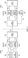
- FIG. 1 depicts an example process (100) for data compression and decompression using luma and chroma reshaping according to an embodiment of this invention.
- a video sequence may be available in both high dynamic range (EDR, 102) and standard dynamic range (SDR, 104) formats.
- the SDR sequence may be generated based on the EDR sequence.
- the EDR sequence may be generated based on the SDR sequence.
- the "look" in both the input EDR and SDR sequences (as represented by their luminance and color pixel values) represent the artistic intent or "look" of the director.
- Inputs (102) and (104) may be coded according to certain EOTF (e.g., gamma, PQ, and the like).
- Forward reshaping may include separate luma reshaping (105-A) and chroma reshaping (105-B) processes.
- Luma reshaping (105-A) and chroma reshaping (105-B) processes may be applied to the input EDR signal (102), taking into consideration the characteristics of the reference SDR signal (104), to generate a reshaped SDR signal (107) with corresponding luma (107-L) and chroma (107-C) components.
- forward reshaping (105) may also include processes related to color conversion, tone mapping, and saturation control.
- video signal (107) is delivered to encoding block (110) for delivering downstream to decoding and playback devices such as television sets, set-top boxes, movie theaters, and the like.
- coding block (110) may include audio and video encoders, such as those defined by ATSC, DVB, DVD, Blu-Ray, and other delivery formats, to generate coded bit stream (112).
- the coded bit stream (112) is decoded by decoding unit (115) to generate a decoded signal (117) representing an identical or close approximation of signal (107).
- decoded signal (117) may be displayed directly to SDR display (130).
- decoded signal (117) may be processed by a backward or inverse reshaping function (120), which converts the reshaped signal back to its original (higher) dynamic range, to be displayed on an HDR display (125).
- Inverse reshaping may include separate inverse luma reshaping (120-A) and chroma reshaping (120-B).
- inverse reshaping may also include additional (inverse) processes, such as inverse tone-mapping, color transformations, and the like.
- the backward or inverse reshaping function (120) may be integrated with a de-quantizer in decoder (115), e.g., as part of the de-quantizer in an AVC or HEVC video decoder.
- information about the reshaping process (105) may be communicated to downstream devices (such as decoders) using metadata, SEI messaging, and the like.
- the encoder a) collects statistics for each frame within a scene, b) calculates the forward reshaping and backward reshaping functions, and c) applies the reshaping function to the entire scene.
- This allows an encoder to better manage sudden jumps in the luminance and/or chroma characteristics of the input due to scene changes.
- FIG. 2a An example of such a process is shown in FIG. 2a , where in an example multi-processing system with three computing nodes, each scene (Scene 0 to Scene 2) is processed separately by each node (Node 0 to Node 2).
- the encoding farm consists of multiple nodes in a computing cloud, where each node is assigned to encode a fixed interval (segment) of the video for better timing and schedule management.
- Typical segment sizes range in length between 10 to 30 seconds.
- a segment may have a total of 720 frames or pictures.
- FIG. 2b An example of such process is depicted in FIG. 2b , where the three original scenes are now divided into five equal segments (Sg.0 to Sg. 4), wherein each segment is assigned to a separate computing node (Node 0 to Node 4).
- a scene e.g., Scene 0
- can cross multiple segments Sg. 0, Sg.1, and Sg. 2
- a segment e.g., Sg. 2
- can include frames from multiple scenes e.g., Sg. 2a belongs to Scene 0 and Sg. 2b belongs to Scene 1).
- an encoder encodes each sub-scene individually, via local optimization. In this scenario, discontinuity in image characteristics (such as a sudden luminance change or a sudden color change) will be observed within this scene.
- padded segment 0 may be encoded by both Node 0 and Node 1
- padded segment 1 Psg. 1
- This approach offers better transition at the boundaries; however, it requires additional encoding computations due to the overlapped encoding and may also require inter-node communications.
- reshaping functions are generated based on statistics from extended or padded segments.
- padded segment 1 (205, Psg. 1) in FIG. 2c .
- This segment includes three parts (or sub-segments): padded frames (205-1), to be encoded by Node 0, primary frames (205-2), to be encoded by Node 1, and padded frames (205-3), to be encoded by Node 2; however, when Node 1 computes a reshaping function to be applied to sub-segment 205-2, it may consider statistics from padded frames belonging to both 205-1 and 205-2 or to both 205-2 and 205-3.
- This approach allows for a) improving the local statistics based on neighbor segments, and b) applying parallel processing across nodes without passing information between nodes.
- a segment may include one or more scene cuts.
- padded segments may include frames from the prior or the subsequent segment to improve the generation of statistical data, such as masking thresholds.
- W 15 frames
- frames in the window belonging to another scene may be dropped from this statistics-gathering window.
- This final window for the j -th frame within the t-th segment will be denoted as the "support frame set" ⁇ t,j .
- FIG. 3 Three examples of support frames sets are depicted in FIG. 3 , where the primary frames (300-1) of the coding (or reshaping) segment are between frames (304) and (306) and the padded segment, which includes padded frames (300-2) and (300-3), is defined between frames (302) and (308).
- F t a segment t with a total number of frames denoted as F t , e.g., all frames in (300-1), between (304) and (306).
- F t a total number of frames
- F t e.g., all frames in (300-1)
- f SCl denote the beginning of the first scene cut immediately before the current frame F
- f SCr denote a scene cut immediately after the current frame F.
- the sliding window (F-W, F+W) goes beyond the left scene cut ( f SCl ), hence, given there is no scene cut to the right, the support frame set (320) is constrained to be within the left scene cut ( f SCl ) and F+W.
- the left scene cut ( f SCl ) is outside of the sliding window (F-W, F+W), hence the support frame set (330) includes all the frames in the sliding window ( F-W , F+W).
- the right scene cut ( f SCr ) is within the sliding window ( F-W, F + W ), hence the support frame set (340) is constrained to be within F-W and f SCr -1 .
- the padded areas may also include W frames each, but may also include less than W frames each, depending on the bandwidth constraints.
- the reshaping function may be computed according to a noise mask histogram of the input image so that quantization noise is not perceived by the human observers.
- a noise measurement e.g., the standard deviation within a block of pixels centered around pixel p
- H j ( p ) the set of pixels with valid noise measurement within frame j .
- i an index inside ⁇ j . Therefore, the set of valid standard deviation measurements may be denoted as H j i , i ⁇ ⁇ j .
- M 16, 32, or 64
- W b 65,536/ M
- b j , m mean H j i
- b m j min b f , m
- b m j 1 ⁇ t , j ⁇ f ⁇ ⁇ t , j b f , m , where, given set X ,
- the set of d i j values denotes the lower bound of required codewords.
- Any quantization (reshaping) curve should satisfy this lower bound to avoid generating quantization-related noise artifacts, such as contouring.
- any reshaping (105) to preserve the director's artistic intent as expressed by the color grading of the reference EDR (102) and SDR (104) inputs, so that the "look" of the decoded streams (e.g., (117) and (122)) matches, respectively, the look of the input streams (e.g., (104) and (102)).
- color grading operations are recorded (e.g., as metadata) as Lift, Gain, and Gamma (LGG), or Slope, Offset, and Power (SOP) operations.
- LGG Lift, Gain, and Gamma
- SOP Slope, Offset, and Power
- luma reshaping based on the efficient matching of luma histograms is described in Ref.[6].
- an alternative method, based on matching cumulative distribution functions (CDF) is also presented herein.
- the ultimate goal is to match the luma looks between the reference SDR (104) and the mapped sequence (107).
- an EDR to SDR luma reshaping function (105-A) should produce a mapped SDR image (107-L) that has luma histogram distribution similar to that of the reference SDR.
- FIG. 4 depicts examples of the c j v . (410) and c j s . (405) CDFs for normalized input codewords and normalized CDF values in (0, 1).
- This process may be repeated for all possible x v codewords in the j -th frame to generate the l i j mapping.
- the CDF curves will be stored as discrete values. For such cases, if the value c is not present in c j s , then known interpolation techniques, such as linear interpolation, may be employed to generate the mapped value x s .
- T i j denote a forward LUT which is obtained by merging together the CDF based luma reshaping LUT l i j (e.g., as expressed by equation (14)) and the required codeword lower bound d i j (e.g., see equation (11)).
- T i j a forward LUT which is obtained by merging together the CDF based luma reshaping LUT l i j (e.g., as expressed by equation (14)) and the required codeword lower bound d i j (e.g., see equation (11)).
- the final forward reshaping mapping is a combination of a) codeword allocation based on applying masking noise thresholds to collected noise characteristics of the input EDR signals and b) an EDR to SDR mapping that preserves the director's intent or "look."
- the two results may be combined as follows.
- Codeword allocation in the bins that violate the lower bound constraints is replaced with lower codeword allocation bounds; that is: Codeword allocation in the bins which do not violate the lower bound is rescaled to keep the number of codewords constant.
- ⁇ i j ⁇ l i j ⁇ 1 ⁇ ⁇ ⁇ for all i ⁇ ⁇ j .
- the merging process may be repeated again until the lower bound is satisfied.
- the entries in the FLUT e.g., from equation (15)
- the entries in the FLUT may be smoothened with an averaging filter and rescaled to maintain the overall codeword budget.
- the M ( . ) mapping may be bypassed and one may use only the codewords generated from the original lower bound requirements.
- the j -th frame may be selected to be mapped using the average FLUT (say, FLUT ), using an average or a weighted average of the individual FLUT mappings.
- chroma reshaping may be based on a multivariate, multiple regression (MMR) representation. Examples of such MMR predictors may be found in U.S.
- u ex T [ v t , j , p Y 3 v t , j , p Cb 3 v t , j , p Cr 3 v t , j , p Y 3 v t , j , p Cb 3 v t , j , p Y 3 v t , j , p Cb 3 v t , j , p Y 3 v t , j , p Cr 3 v t , j , p Cb 3 v t , j , p Cr 3 v t , j , p Cb 3 v t , j , p Cr 3 v t , j , p Cb 3 v t , j , p Cr 3 v t , j , p Y v t , j , p Cr 3
- the goal is to determine a set of MMR coefficients M t , j F , such that the predicted SDR value, c ⁇ t,j,p , is closest to s t,j,p according to some optimization criterion, such as optimizing the mean square error (MSE).
- MSE mean square error
- all w t,j,k weights may be equal (e.g., equal to 1).
- the weights may follow a certain distribution function (e.g., exponential, Gaussian, and the like) so that neighboring frames at the center of the sliding window have more weight than frames at the edges of the sliding window.
- a backward chroma reshaping function based on an MMR model, needs to be determined so that reconstructed EDR pixels are as close as possible to the original EDR pixels.
- the vector h t,j,p may also be expressed as a combination of first, second, and/or third order terms of h t,j.p according to a backward-reshaping MMR model.
- an extra W B frames are required from the reshaped SDR, given by C ⁇ t ⁇ 1 , F t ⁇ 1 ⁇ 1 C ⁇ t ⁇ 1 , F t ⁇ 1 ⁇ 2 C ⁇ t ⁇ 1 , F t ⁇ 1 ⁇ 3 ⁇ C ⁇ t ⁇ 1 , F t ⁇ 1 ⁇ W B , and extra smoothed W B frames at the next segment are required, given by, C ⁇ t + 1,0 C ⁇ t + 1,1 C ⁇ t + 1,2 ⁇ C ⁇ t + 1 , W B ⁇ 1 .
- FIG. 5A depicts a process of overlapped forward chroma reshaping in an EDR/HDR encoder according to an embodiment of this invention.
- a forward prediction parameter matrix M t , j F may be generated according to an MSE optimization criterion (e.g., equation (46)).
- FIG. 5B depicts a process of overlapped backward chroma reshaping in an EDR/HDR encoder according to an embodiment of this invention.
- a backward prediction parameter matrix M t , j B may be generated according to an MSE optimization criterion (e.g., equation (50)).
- the order of the MMR backward model and the backward prediction parameter matrix M t , j B may be communicated to a decoder using metadata together with the encoded reshaped SDR signal (107).
- FIG. 6 summarizes the process for segment-based luma and chroma reshaping according to an example embodiment of this invention.
- the input streams are subdivided into segments for each computing node.
- Each node receives extended or padded data (to also be processed by neighboring segments) (e.g., see FIG. 3 ) to improve the generation of statistical data and reduce the effects from scene changes.
- a reshaping function for each frame in a segment is computed based on the statistical data available in a support frame set bounded by a 2 W +1 frames-long sliding window centered on the frame.
- the borders of this window are adjusted based on the scene cuts within the segment to generate the support frame set (e.g., see FIG. 3 and equations (1) and (2)).
- step (615) determines the minimum amount of codewords for each bin in the input image (e.g., see equation (11)).
- step (620) one may also determine an EDR to reshaped SDR mapping which preserves the "look" of the reference SDR in the reshaped SDR image. For example, and without limitation, such a mapping may be based on matching either the histograms or the CDFs of the input SDR and EDR images.
- step (625) the results from steps (615) and (620) are combined so that the look is preserved while the reshaping meets the codeword allocation required to mask the quantization noise due to reshaping.
- step (630) Given the final forward luma reshaping LUT, step (630) generates the reshaped luma image (107-L). In some embodiments, this step may also generate an inverse luma-reshaping function based on the forward luma reshaping LUT to be communicated downstream to the receiver (e.g.,, as a piecewise linear or non-linear function). Examples of these steps can be found in References [4] and [5].
- step (640) may apply a forward MMR prediction model and a forward support frame set to generate, according to an optimizing criterion, the forward chroma reshaping parameters (e.g., see equation (46)), to be used in step (650) to generate the chroma components (107-C) of the reshaped SDR signal (107).
- Step (660) may use a backward MMR model and a backward support frame set to generate the backward reshaping parameters (e.g., using equation (42)), which are communicated to the downstream receiver using metadata.
- the reshaped SDR signal (107), together with metadata related to the backward or inverse luma and chroma reshaping functions may be passed to an encoder (110) for further processing.
- a special case of interest is the encoding of video signals in linear broadcasting where video is encoded and delivered to the users in real time.
- the number of segments is set to one.
- Embodiments of the present invention may be implemented with a computer system, systems configured in electronic circuitry and components, an integrated circuit (IC) device such as a microcontroller, a field programmable gate array (FPGA), or another configurable or programmable logic device (PLD), a discrete time or digital signal processor (DSP), an application specific IC (ASIC), and/or apparatus that includes one or more of such systems, devices or components.
- IC integrated circuit
- FPGA field programmable gate array
- PLD configurable or programmable logic device
- DSP discrete time or digital signal processor
- ASIC application specific IC
- the computer and/or IC may perform, control, or execute instructions related to segment-based luma and chroma reshaping of images with enhanced dynamic range, such as those described herein.
- the computer and/or IC may compute any of a variety of parameters or values that relate to the reshaping processes described herein.
- the image and video embodiments may be implemented in hardware, software, firmware and
- Certain implementations of the invention comprise computer processors which execute software instructions which cause the processors to perform a method of the invention.
- processors in a display, an encoder, a set top box, a transcoder or the like may implement methods related to segment-based luma and/or chroma reshaping of HDR images as described above by executing software instructions in a program memory accessible to the processors.
- the invention may also be provided in the form of a program product.
- the program product may comprise any non-transitory medium which carries a set of computer-readable signals comprising instructions which, when executed by a data processor, cause the data processor to execute a method of the invention.
- Program products according to the invention may be in any of a wide variety of forms.
- the program product may comprise, for example, physical media such as magnetic data storage media including floppy diskettes, hard disk drives, optical data storage media including CD ROMs, DVDs, electronic data storage media including ROMs, flash RAM, or the like.
- the computer-readable signals on the program product may optionally be compressed or encrypted.
- a component e.g. a software module, processor, assembly, device, circuit, etc.
- reference to that component should be interpreted as including as equivalents of that component any component which performs the function of the described component (e.g., that is functionally equivalent), including components which are not structurally equivalent to the disclosed structure which performs the function in the illustrated example embodiments of the invention.
Claims (14)
- Verfahren für segmentbasierte Signalumformung mit einem Prozessor, das Verfahren umfassend:Empfangen eines ersten Eingangsvideosignals in einem ersten dynamischen Bereich und eines zweiten Eingangsvideosignals in einem zweiten dynamischen Bereich, wobei entsprechende Frames in dem ersten Signal und dem zweiten Signal dasselbe Bild darstellen, wobei der erste dynamische Bereich höher ist als der zweite dynamische Bereich;Teilen des ersten Eingangsvideosignals und des zweiten Eingangsvideosignals in Segmente, wobei jedes Segment primäre Frames und Füllframes umfasst, wobei die primären Frames jene Frames in dem Segment sind, für die eine Vorwärts-Luma-Umformungsabbildung erzeugt wird, wobei die Füllframes in dem Segment vor einem ersten der primären Frames und/oder nach einem letzten der primären Frames angeordnet sind, und wobei für zwei aufeinanderfolgende Segmente Füllframes für eines der Segmente mit den primären Frames des anderen Segments überlappen;für einen primären Frame in einem Segment des ersten Eingangsvideos:Berechnen eines Hilfsframesatzes in dem Segment basierend auf einem Gleitfenster, das auf dem primären Frame zentriert ist, wobei der Hilfsframesatz durch Einstellen des Gleitfensters basierend auf Szenenausschnitten in dem Segment erhalten wird, sodass Frames der Gleitfenster, die nicht in derselben Szene enthalten sind wie der primäre Frame, aus dem Hilfsframesatz ausgeschlossen sind;Bestimmen einer minimalen Codewortzuordnung für Luminanzpixelwerte in einem umgeformten Frame des primären Frames, wobei die minimale Codewortzuordnung für jedes Paar benachbarter Codewörter in dem primären Frame eine erforderliche Menge an Codewörtern in dem umgeformten Frame angibt, wobei Bestimmen der minimalen Codewortzuordnung umfasst:Trennen des Luminanzbereichs des primären Frames in nicht-überlappende Bins;Erzeugen von Rauschschätzungen für jeden Bin basierend auf einem Rauschmesskriterium und dem Hilfsframesatz; undErzeugen der minimalen Codewortzuordnung basierend auf der Eingangsbittiefe des ersten Eingangs, einer Zielbittiefe des umgeformten Frames und einer Funktion zur Abbildung von Rauschschätzungen auf Bittiefen;Bestimmen einer Abbildung eines ersten dynamischen Bereichs auf einen zweiten dynamischen Bereich für Abbildung von Luminanzwerten des primären Frames von dem ersten dynamischen Bereich auf den zweiten dynamischen Bereich basierend auf einer Luma-Umformungsfunktion und dem Hilfsframesatz, wobei die Luma-Umformungsfunktion die Abbildung eines ersten dynamischen Bereichs auf einen zweiten dynamischen Bereich durch Übereinstimmen von Histogrammcharakteristika von Luminanzwerten in einem abgebildeten Frame auf die Histogrammcharakteristika von Luminanzwerten in einem Frame in dem zweiten Videosignal entsprechend dem primären Frame erzeugt, wobei der abgebildete Frame durch Anwenden der Abbildung eines ersten dynamischen Bereichs auf einen zweiten dynamischen Bereich an dem primären Frame erzeugt wird;Kombinieren der Abbildung eines ersten dynamischen Bereichs auf einen zweiten dynamischen Bereich mit der minimalen Codewortzuordnung, um die Vorwärts-Luma-Umformungsabbildung zu erzeugen; undAnwenden der erzeugten Vorwärts-Luma-Umformungsabbildung an dem primären Frame zum Abbilden des primären Frames von dem ersten dynamischen Bereich auf den zweiten dynamischen Bereich, um Luminanzwerte eines umgeformten Ausgangsframes zu erzeugen.
- Verfahren nach Anspruch 1, wobei die minimale Codewortzuordnung basierend auf einem Rauschmaskierungsschwellenwert für den primären Frame bestimmt wird, wobei optional der Rauschmaskierungsschwellenwert basierend auf Rauschmessungen für die Frames des Hilfsframesatzes bestimmt wird.
- Verfahren nach einem der Ansprüche 1 bis 2, wobei die minimale Codewortzuordnung eine unter Grenze bei einer Zuordnung von Ausgangscodewörtern in dem umgeformten Frame über Eingangscodewörter in dem primären Frame angibt.
- Verfahren nach einem vorstehenden Anspruch, wobei Berechnen des Hilfsframesatzes umfasst:Bestimmen eines Fensters aus 2W+1 Frames, zentriert auf den primären Frame;Bestimmen eines ersten Szenenausschnitts in dem Segment, das der linken Seite des primären Frames am nächsten ist;Bestimmen eines zweiten Szenenausschnitts in dem Segment, das der rechten Seite des primären Frames am nächsten ist;Einstellen der linken Seite des Fensters als den Beginn des ersten Szenenausschnitts in dem Segment, wenn die Position des ersten Szenenausschnitts innerhalb von W Frames an der linken Seite des primären Frames ist; undEinstellen der rechten Seite des Fensters vor der Position des zweiten Szenenausschnitts in dem Segment, wenn die Position des zweiten Szenenausschnitts innerhalb von W Frames an der rechten Seite des primären Frames ist, wobei W eine ganze Zahl ist.
- Verfahren nach einem vorstehenden Anspruch, wobei Bestimmen der Abbildung eines ersten dynamischen Bereichs auf einen zweiten dynamischen Bereich zum Abbilden von Luminanzwerten des primären Frames von dem ersten dynamischen Bereich auf den zweiten dynamischen Bereich basierend auf einer Luma-Umformungsfunktion umfasst:Berechnen eines ersten normalisierten Luminanzhistogramms für jeden Frame in dem Hilfsframesatz;Berechnen einer ersten kumulativen Dichtefunktion, CDF, für den primären Frame basierend auf den ersten normalisierten Luminanzhistogrammen;Berechnen eines zweiten normalisierten Luminanzhistogramms für jeden Frame in dem zweiten Eingangsvideo, der einem Frame in dem Hilfsframesatz entspricht;Berechnen einer zweiten CDF basierend auf den zweiten normalisierten Luminanzhistogrammen; undfür jeden Luma-Intensitätswert in dem primären Frame, Bestimmen eines ersten abgebildeten Luma-Werts, sodass der Ausgangswert der ersten CDF für den Luma-Intensitätswert annähernd gleich dem Ausgangswert der zweiten CDF für den ersten abgebildeten Luma-Wert ist.
- Verfahren nach einem vorstehenden Anspruch, wobei Kombinieren der Abbildung eines ersten dynamischen Bereichs auf einen zweiten dynamischen Bereich mit der minimalen Codewortzuordnung umfasst:Erzeugen, als Deltawerte, paarweiser Differenzen zwischen abgebildeten Codewörtern aufeinanderfolgender Codewörter, wobei die aufeinanderfolgenden Codewörter durch die Abbildung eines ersten dynamischen Bereichs auf einen zweiten dynamischen Bereich abgebildet werden;Identifizieren eines ersten Satzes von Elementen der Deltawerte, die die Anforderungen einer minimalen Codewortzuordnung verletzen;Bestimmen einer ersten Metrik (α) von Codewortanforderungen, die für den ersten Satz von Elementen hinzuzufügen sind, wobei die erste Metrik eine zusätzliche Menge an erforderlichen Codewörtern zur Erfüllung der Anforderungen einer minimalen Codewortzuordnung angibt;Identifizieren eines zweiten Satzes von Elementen der Deltawerte, die die Anforderungen einer minimalen Codewortzuordnung nicht verletzen;Bestimmen einer zweiten Metrik (β) von Codewortanforderungen, die für den zweiten Satz von Elementen abzuziehen sind, wobei die zweite Metrik eine Summe jener Deltawerte angibt, die die Anforderungen einer minimalen Codewortzuordnung nicht verletzen;für den ersten Satz von Elementen, Ersetzen ihrer Deltawerte mit ihren entsprechenden Anforderungswerten einer minimalen Codewortzuordnung;für den zweiten Satz von Elementen, Neuskalieren ihrer Deltawerte basierend auf der ersten Metrik und der zweiten Metrik; undErzeugen einer Vorwärtsumformung-LUT basierend auf den aktualisierten Werten des ersten Satzes von Elementen und des zweiten Satzes von Elementen, wobei optional Neuskalieren Multiplizieren jedes ursprünglichen Deltawerts in dem zweiten Satz von Elementen mit

- Verfahren nach einem vorstehenden Anspruch, weiter umfassend:Bestimmen von Vorwärts-Luma-Umformungsabbildungen für zwei oder mehr der Frames, die zu dem Hilfsframesatz des primären Frames gehören; undBestimmen einer durchschnittlichen Vorwärts-Luma-Umformungsabbildung basierend auf einem Durchschnitt oder gewichteten Durchschnitt der Vorwärts-Luma-Umformungsabbildungen für die zwei oder mehr Frames in dem Hilfsframesatz des primären Frames.
- Verfahren nach Anspruch 7, weiter umfassend:
Anwenden der Vorwärts-Luma-Umformungsabbildung für den primären Frame an den Luminanzpixelwerten des primären Frames, um Luminanzwerte eines umgeformten Ausgangsframes zu erzeugen. - Verfahren nach Anspruch 8, weiter umfassend:
Bestimmen eines Satzes von Umformungs-Chromaparametern für Vorwärts-Chroma-Umformung basierend auf einem multivariaten Vorwärts-Multiregressionsmodell, MMR, und eines Hilfsframesatzes für Vorwärts-Chroma-Umformung durch Minimieren des MSE-Fehlers zwischen Chromawerten in dem umgeformten Ausgangsframe und Chromawerten in dem Frame des zweiten Eingangsvideos entsprechend dem primären Frame. - Verfahren nach Anspruch 8 oder 9, weiter umfassend Bestimmen eines Satzes von Umformungs-Chromaparametern für Rückwärts-Chroma-Umformung basierend auf einem Rückwärts-MMR-Modell und einem Hilfsframesatz zur Rückwärts-Chroma-Umformung durch Minimieren des MSE-Fehlers zwischen Chromawerten in einem rekonstruierten Ausgangsbild in dem ersten dynamischen Bereich und Chromawerten in dem primären Frame des ersten Eingangsvideos.
- Verfahren nach Anspruch 9 oder 10, wobei der MSE-Fehler gewichteter MSE ist.
- Verfahren nach einem der Ansprüche 9 bis 11, weiter umfassend Anwenden des Vorwärts-MMR-Modells an dem primären Frame, um Chrominanzwerte des umgeformten Ausgangsframes zu erzeugen.
- Einrichtung, umfassend einen Prozessor und konfiguriert, eines der in Ansprüchen 1-12 angeführten Verfahren durchzuführen.
- Computerlesbares Speichermedium, umfassend Anweisungen, die, wenn durch einen Computer umgesetzt, den Computer veranlassen, das Verfahren nach einem der Ansprüche 1-12 auszuführen.
Applications Claiming Priority (3)
| Application Number | Priority Date | Filing Date | Title |
|---|---|---|---|
| US201662385307P | 2016-09-09 | 2016-09-09 | |
| EP16187983 | 2016-09-09 | ||
| PCT/US2017/050980 WO2018049335A1 (en) | 2016-09-09 | 2017-09-11 | Coding of high dynamic range video using segment-based reshaping |
Publications (2)
| Publication Number | Publication Date |
|---|---|
| EP3510772A1 EP3510772A1 (de) | 2019-07-17 |
| EP3510772B1 true EP3510772B1 (de) | 2020-12-09 |
Family
ID=59895469
Family Applications (1)
| Application Number | Title | Priority Date | Filing Date |
|---|---|---|---|
| EP17768653.2A Active EP3510772B1 (de) | 2016-09-09 | 2017-09-11 | Codierung von video mit hohem dynamikbereich mittels segmentbasierter neuformung |
Country Status (2)
| Country | Link |
|---|---|
| US (1) | US10575028B2 (de) |
| EP (1) | EP3510772B1 (de) |
Families Citing this family (23)
| Publication number | Priority date | Publication date | Assignee | Title |
|---|---|---|---|---|
| EP3695600A4 (de) | 2017-11-30 | 2020-08-19 | SZ DJI Technology Co., Ltd. | System und verfahren zur steuerung der videocodierung innerhalb eines bildrahmens |
| WO2019104862A1 (en) * | 2017-11-30 | 2019-06-06 | SZ DJI Technology Co., Ltd. | System and method for reducing video coding fluctuation |
| WO2019104635A1 (en) | 2017-11-30 | 2019-06-06 | SZ DJI Technology Co., Ltd. | System and method for controlling video coding at frame level |
| BR112020016821B1 (pt) | 2018-02-28 | 2022-08-09 | Dolby Laboratories Licensing Corporation | Método de geração de metadados de remodelagem de luma e croma com um sistema de processamento, meio legível por máquina e sistema de gerenciamento de exibição |
| JP6964807B2 (ja) | 2018-05-11 | 2021-11-10 | ドルビー ラボラトリーズ ライセンシング コーポレイション | エンドツーエンド単一レイヤの下位互換性のある符号化パイプラインにおける、高忠実度の完全参照及び低減参照符号化 |
| EP3861729A1 (de) * | 2018-10-03 | 2021-08-11 | Dolby Laboratories Licensing Corporation | Reduzierung von banding-artefakten bei rückwärtskompatibler hdr-bildgebung |
| KR20210118400A (ko) * | 2019-02-01 | 2021-09-30 | 베이징 바이트댄스 네트워크 테크놀로지 컴퍼니, 리미티드 | 비디오 코딩을 위한 루마 종속적 크로마 잔차 스케일링의 구성 |
| CN113475079A (zh) | 2019-02-01 | 2021-10-01 | 北京字节跳动网络技术有限公司 | 环路整形和帧内块复制之间的相互作用 |
| CN113475072B (zh) * | 2019-03-04 | 2023-12-15 | 北京字节跳动网络技术有限公司 | 视频处理中滤波信息的信令 |
| WO2020182091A1 (en) * | 2019-03-08 | 2020-09-17 | Beijing Bytedance Network Technology Co., Ltd. | Reshaping model in video processing |
| CN117499644A (zh) | 2019-03-14 | 2024-02-02 | 北京字节跳动网络技术有限公司 | 环路整形信息的信令和语法 |
| WO2020192614A1 (en) | 2019-03-23 | 2020-10-01 | Beijing Bytedance Network Technology Co., Ltd. | Restrictions on adaptive-loop filtering parameter sets |
| WO2020211863A1 (en) | 2019-04-18 | 2020-10-22 | Beijing Bytedance Network Technology Co., Ltd. | Selective use of cross component mode in video coding |
| CN113711610B (zh) | 2019-04-23 | 2024-04-16 | 北京字节跳动网络技术有限公司 | 降低跨分量依赖性的方法 |
| KR102641796B1 (ko) | 2019-05-08 | 2024-03-04 | 베이징 바이트댄스 네트워크 테크놀로지 컴퍼니, 리미티드 | 교차-성분 코딩의 적용가능성에 대한 조건들 |
| WO2020259427A1 (en) | 2019-06-22 | 2020-12-30 | Beijing Bytedance Network Technology Co., Ltd. | Syntax element for chroma residual scaling |
| JP7460748B2 (ja) | 2019-07-07 | 2024-04-02 | 北京字節跳動網絡技術有限公司 | クロマ残差スケーリングのシグナリング |
| US11818400B2 (en) | 2019-10-17 | 2023-11-14 | Dolby Laboratories Licensing Corporation | Adjustable trade-off between quality and computation complexity in video codecs |
| EP4139884B1 (de) * | 2020-04-22 | 2024-02-21 | Dolby Laboratories Licensing Corporation | Iterative optimierung von umformungsfunktionen in einem einzelschicht-hdr-bild-codec |
| US20230291937A1 (en) * | 2020-07-09 | 2023-09-14 | Dolby Laboratories Licensing Corporation | Workload allocation and processing in cloud-based coding of hdr video |
| WO2022061169A1 (en) | 2020-09-18 | 2022-03-24 | Dolby Laboratories Licensing Corporation | Trim-pass correction for cloud-based coding of hdr video |
| JP2023542897A (ja) * | 2020-09-18 | 2023-10-12 | ドルビー ラボラトリーズ ライセンシング コーポレイション | Hdrビデオのクラウド・ベースの符号化のための再帰的なセグメントからシーンへのセグメンテーション |
| WO2023022956A1 (en) | 2021-08-16 | 2023-02-23 | Dolby Laboratories Licensing Corporation | Applying minimum and average distance constraint in video streaming |
Family Cites Families (28)
| Publication number | Priority date | Publication date | Assignee | Title |
|---|---|---|---|---|
| JP4129812B2 (ja) * | 2001-05-24 | 2008-08-06 | 株式会社リコー | 画像処理方法,装置および画像形成装置 |
| US7254271B2 (en) * | 2003-03-05 | 2007-08-07 | Seadragon Software, Inc. | Method for encoding and serving geospatial or other vector data as images |
| KR100596982B1 (ko) * | 2004-12-15 | 2006-07-05 | 삼성전자주식회사 | 이중 계층 버스 구조, 이중 계층 버스 구조를 가진 시스템온 칩 시스템 및 시스템 온 칩 시스템의 버스 액세스 방법 |
| CN101742306A (zh) * | 2006-01-23 | 2010-06-16 | 马普科技促进协会 | 高动态范围编解码器 |
| CA2570090C (en) * | 2006-12-06 | 2014-08-19 | Brightside Technologies Inc. | Representing and reconstructing high dynamic range images |
| CN101682761B (zh) | 2007-06-14 | 2013-03-20 | 汤姆森许可贸易公司 | 进行时间最优化编码的系统和方法 |
| US8330768B2 (en) * | 2007-07-27 | 2012-12-11 | Sharp Laboratories Of America, Inc. | Apparatus and method for rendering high dynamic range images for standard dynamic range display |
| US8339475B2 (en) * | 2008-12-19 | 2012-12-25 | Qualcomm Incorporated | High dynamic range image combining |
| US8280184B2 (en) * | 2010-04-01 | 2012-10-02 | Himax Media Solutions, Inc. | Image enhancement method and apparatuses utilizing the same |
| US20110292992A1 (en) * | 2010-05-28 | 2011-12-01 | Microsoft Corporation | Automating dynamic information insertion into video |
| KR101538912B1 (ko) * | 2010-06-08 | 2015-07-23 | 돌비 레버러토리즈 라이쎈싱 코오포레이션 | 색조 및 색역 맵핑 방법들 및 장치 |
| US8743291B2 (en) * | 2011-04-12 | 2014-06-03 | Dolby Laboratories Licensing Corporation | Quality assessment for images that have extended dynamic ranges or wide color gamuts |
| EP2697971B1 (de) | 2011-04-14 | 2015-07-08 | Dolby Laboratories Licensing Corporation | Prädiktor mit multiplen regressionen und multiplen farbkanälen |
| US8891863B2 (en) * | 2011-06-13 | 2014-11-18 | Dolby Laboratories Licensing Corporation | High dynamic range, backwards-compatible, digital cinema |
| US8576445B2 (en) * | 2011-06-28 | 2013-11-05 | Konica Minolta Laboratory U.S.A., Inc. | Method for processing high dynamic range images using tone mapping to extended RGB space |
| US8988552B2 (en) * | 2011-09-26 | 2015-03-24 | Dolby Laboratories Licensing Corporation | Image formats and related methods and apparatuses |
| CN104185991B (zh) * | 2011-11-09 | 2018-07-06 | 弗劳恩霍夫应用研究促进协会 | 不同动态采样值范围的层之间的层间预测 |
| US20130308027A1 (en) * | 2012-05-03 | 2013-11-21 | Aptina Imaging Corporation | Systems and methods for generating metadata in stacked-chip imaging systems |
| US11089247B2 (en) * | 2012-05-31 | 2021-08-10 | Apple Inc. | Systems and method for reducing fixed pattern noise in image data |
| EP2748792B1 (de) * | 2012-08-08 | 2016-12-21 | Dolby Laboratories Licensing Corporation | Bildverarbeitung für hdr-bilder |
| FR3003378A1 (fr) * | 2013-03-12 | 2014-09-19 | St Microelectronics Grenoble 2 | Procede de mappage de tons |
| RU2619886C2 (ru) | 2013-03-26 | 2017-05-19 | Долби Лабораторис Лайсэнзин Корпорейшн | Кодирование перцепционно-квантованного видеоконтента в многоуровневом кодировании vdr |
| US8866975B1 (en) * | 2013-05-02 | 2014-10-21 | Dolby Laboratories Licensing Corporation | Backwards-compatible delivery of digital cinema content with higher dynamic range and related preprocessing and coding methods |
| EP3024222A4 (de) * | 2013-07-14 | 2017-01-18 | LG Electronics Inc. | Verfahren und vorrichtung zum senden und empfangen ultrahochauflösender rundfunksignale zur expression von hochwertiger farbe in einem digitalen rundfunksystem |
| WO2016014954A1 (en) | 2014-07-25 | 2016-01-28 | California Institute Of Technology | Tandem z-selective metathesis / dihydroxylation |
| US10419762B2 (en) | 2015-03-02 | 2019-09-17 | Dolby Laboratories Licensing Corporation | Content-adaptive perceptual quantizer for high dynamic range images |
| US10032262B2 (en) | 2016-02-02 | 2018-07-24 | Dolby Laboratories Licensing Corporation | Block-based content-adaptive reshaping for high dynamic range images |
| GB201611253D0 (en) | 2016-06-29 | 2016-08-10 | Dolby Laboratories Licensing Corp | Efficient Histogram-based luma look matching |
-
2017
- 2017-09-11 EP EP17768653.2A patent/EP3510772B1/de active Active
- 2017-09-11 US US16/324,468 patent/US10575028B2/en active Active
Non-Patent Citations (1)
| Title |
|---|
| None * |
Also Published As
| Publication number | Publication date |
|---|---|
| US20190349607A1 (en) | 2019-11-14 |
| EP3510772A1 (de) | 2019-07-17 |
| US10575028B2 (en) | 2020-02-25 |
Similar Documents
| Publication | Publication Date | Title |
|---|---|---|
| EP3510772B1 (de) | Codierung von video mit hohem dynamikbereich mittels segmentbasierter neuformung | |
| EP3433833B1 (de) | Codierung und decodierung von einzelschichtvideosignalen mit umkehrbarer produktionsqualität | |
| CN112106357B (zh) | 用于对图像数据进行编码和解码的方法及装置 | |
| EP3479343B1 (de) | Effiziente histogrammbasierte luma-look-anpassung | |
| EP3734588A1 (de) | Konservierung der farbwirkung in video-codecs | |
| US10419762B2 (en) | Content-adaptive perceptual quantizer for high dynamic range images | |
| US10645403B2 (en) | Chroma reshaping for high dynamic range images | |
| US10902601B2 (en) | Segment-based reshaping for coding high dynamic range video | |
| US10701359B2 (en) | Real-time content-adaptive perceptual quantizer for high dynamic range images | |
| WO2018049335A1 (en) | Coding of high dynamic range video using segment-based reshaping | |
| EP3834411B1 (de) | Reduzierung von banding-artefakten in hdr-bildgebung über adaptive sdr-zu-hdr-umformungsfunktionen | |
| WO2018231968A1 (en) | Efficient end-to-end single layer inverse display management coding | |
| EP3639238B1 (de) | Effiziente codierung für einschichtige end-to-end-inversanzeigeverwaltung | |
| CN113170205A (zh) | 整形函数的插值 | |
| US11895416B2 (en) | Electro-optical transfer function conversion and signal legalization | |
| WO2018136432A1 (en) | Segment-based reshaping for coding high dynamic range video | |
| EP4214925A1 (de) | Trim-pass-korrektur für cloud-basierte codierung von hdr-video |
Legal Events
| Date | Code | Title | Description |
|---|---|---|---|
| STAA | Information on the status of an ep patent application or granted ep patent |
Free format text: STATUS: UNKNOWN |
|
| STAA | Information on the status of an ep patent application or granted ep patent |
Free format text: STATUS: THE INTERNATIONAL PUBLICATION HAS BEEN MADE |
|
| PUAI | Public reference made under article 153(3) epc to a published international application that has entered the european phase |
Free format text: ORIGINAL CODE: 0009012 |
|
| STAA | Information on the status of an ep patent application or granted ep patent |
Free format text: STATUS: REQUEST FOR EXAMINATION WAS MADE |
|
| 17P | Request for examination filed |
Effective date: 20190409 |
|
| AK | Designated contracting states |
Kind code of ref document: A1 Designated state(s): AL AT BE BG CH CY CZ DE DK EE ES FI FR GB GR HR HU IE IS IT LI LT LU LV MC MK MT NL NO PL PT RO RS SE SI SK SM TR |
|
| AX | Request for extension of the european patent |
Extension state: BA ME |
|
| DAV | Request for validation of the european patent (deleted) | ||
| DAX | Request for extension of the european patent (deleted) | ||
| STAA | Information on the status of an ep patent application or granted ep patent |
Free format text: STATUS: EXAMINATION IS IN PROGRESS |
|
| 17Q | First examination report despatched |
Effective date: 20200207 |
|
| GRAP | Despatch of communication of intention to grant a patent |
Free format text: ORIGINAL CODE: EPIDOSNIGR1 |
|
| STAA | Information on the status of an ep patent application or granted ep patent |
Free format text: STATUS: GRANT OF PATENT IS INTENDED |
|
| INTG | Intention to grant announced |
Effective date: 20200723 |
|
| GRAS | Grant fee paid |
Free format text: ORIGINAL CODE: EPIDOSNIGR3 |
|
| GRAA | (expected) grant |
Free format text: ORIGINAL CODE: 0009210 |
|
| STAA | Information on the status of an ep patent application or granted ep patent |
Free format text: STATUS: THE PATENT HAS BEEN GRANTED |
|
| AK | Designated contracting states |
Kind code of ref document: B1 Designated state(s): AL AT BE BG CH CY CZ DE DK EE ES FI FR GB GR HR HU IE IS IT LI LT LU LV MC MK MT NL NO PL PT RO RS SE SI SK SM TR |
|
| REG | Reference to a national code |
Ref country code: GB Ref legal event code: FG4D |
|
| REG | Reference to a national code |
Ref country code: AT Ref legal event code: REF Ref document number: 1344547 Country of ref document: AT Kind code of ref document: T Effective date: 20201215 Ref country code: CH Ref legal event code: EP |
|
| REG | Reference to a national code |
Ref country code: DE Ref legal event code: R096 Ref document number: 602017029318 Country of ref document: DE |
|
| REG | Reference to a national code |
Ref country code: IE Ref legal event code: FG4D |
|
| PG25 | Lapsed in a contracting state [announced via postgrant information from national office to epo] |
Ref country code: GR Free format text: LAPSE BECAUSE OF FAILURE TO SUBMIT A TRANSLATION OF THE DESCRIPTION OR TO PAY THE FEE WITHIN THE PRESCRIBED TIME-LIMIT Effective date: 20210310 Ref country code: FI Free format text: LAPSE BECAUSE OF FAILURE TO SUBMIT A TRANSLATION OF THE DESCRIPTION OR TO PAY THE FEE WITHIN THE PRESCRIBED TIME-LIMIT Effective date: 20201209 Ref country code: NO Free format text: LAPSE BECAUSE OF FAILURE TO SUBMIT A TRANSLATION OF THE DESCRIPTION OR TO PAY THE FEE WITHIN THE PRESCRIBED TIME-LIMIT Effective date: 20210309 Ref country code: RS Free format text: LAPSE BECAUSE OF FAILURE TO SUBMIT A TRANSLATION OF THE DESCRIPTION OR TO PAY THE FEE WITHIN THE PRESCRIBED TIME-LIMIT Effective date: 20201209 |
|
| REG | Reference to a national code |
Ref country code: AT Ref legal event code: MK05 Ref document number: 1344547 Country of ref document: AT Kind code of ref document: T Effective date: 20201209 |
|
| PG25 | Lapsed in a contracting state [announced via postgrant information from national office to epo] |
Ref country code: BG Free format text: LAPSE BECAUSE OF FAILURE TO SUBMIT A TRANSLATION OF THE DESCRIPTION OR TO PAY THE FEE WITHIN THE PRESCRIBED TIME-LIMIT Effective date: 20210309 Ref country code: LV Free format text: LAPSE BECAUSE OF FAILURE TO SUBMIT A TRANSLATION OF THE DESCRIPTION OR TO PAY THE FEE WITHIN THE PRESCRIBED TIME-LIMIT Effective date: 20201209 Ref country code: SE Free format text: LAPSE BECAUSE OF FAILURE TO SUBMIT A TRANSLATION OF THE DESCRIPTION OR TO PAY THE FEE WITHIN THE PRESCRIBED TIME-LIMIT Effective date: 20201209 |
|
| REG | Reference to a national code |
Ref country code: NL Ref legal event code: MP Effective date: 20201209 |
|
| PG25 | Lapsed in a contracting state [announced via postgrant information from national office to epo] |
Ref country code: NL Free format text: LAPSE BECAUSE OF FAILURE TO SUBMIT A TRANSLATION OF THE DESCRIPTION OR TO PAY THE FEE WITHIN THE PRESCRIBED TIME-LIMIT Effective date: 20201209 Ref country code: HR Free format text: LAPSE BECAUSE OF FAILURE TO SUBMIT A TRANSLATION OF THE DESCRIPTION OR TO PAY THE FEE WITHIN THE PRESCRIBED TIME-LIMIT Effective date: 20201209 |
|
| REG | Reference to a national code |
Ref country code: LT Ref legal event code: MG9D |
|
| PG25 | Lapsed in a contracting state [announced via postgrant information from national office to epo] |
Ref country code: SM Free format text: LAPSE BECAUSE OF FAILURE TO SUBMIT A TRANSLATION OF THE DESCRIPTION OR TO PAY THE FEE WITHIN THE PRESCRIBED TIME-LIMIT Effective date: 20201209 Ref country code: LT Free format text: LAPSE BECAUSE OF FAILURE TO SUBMIT A TRANSLATION OF THE DESCRIPTION OR TO PAY THE FEE WITHIN THE PRESCRIBED TIME-LIMIT Effective date: 20201209 Ref country code: CZ Free format text: LAPSE BECAUSE OF FAILURE TO SUBMIT A TRANSLATION OF THE DESCRIPTION OR TO PAY THE FEE WITHIN THE PRESCRIBED TIME-LIMIT Effective date: 20201209 Ref country code: EE Free format text: LAPSE BECAUSE OF FAILURE TO SUBMIT A TRANSLATION OF THE DESCRIPTION OR TO PAY THE FEE WITHIN THE PRESCRIBED TIME-LIMIT Effective date: 20201209 Ref country code: SK Free format text: LAPSE BECAUSE OF FAILURE TO SUBMIT A TRANSLATION OF THE DESCRIPTION OR TO PAY THE FEE WITHIN THE PRESCRIBED TIME-LIMIT Effective date: 20201209 Ref country code: RO Free format text: LAPSE BECAUSE OF FAILURE TO SUBMIT A TRANSLATION OF THE DESCRIPTION OR TO PAY THE FEE WITHIN THE PRESCRIBED TIME-LIMIT Effective date: 20201209 Ref country code: PT Free format text: LAPSE BECAUSE OF FAILURE TO SUBMIT A TRANSLATION OF THE DESCRIPTION OR TO PAY THE FEE WITHIN THE PRESCRIBED TIME-LIMIT Effective date: 20210409 |
|
| PG25 | Lapsed in a contracting state [announced via postgrant information from national office to epo] |
Ref country code: PL Free format text: LAPSE BECAUSE OF FAILURE TO SUBMIT A TRANSLATION OF THE DESCRIPTION OR TO PAY THE FEE WITHIN THE PRESCRIBED TIME-LIMIT Effective date: 20201209 Ref country code: AT Free format text: LAPSE BECAUSE OF FAILURE TO SUBMIT A TRANSLATION OF THE DESCRIPTION OR TO PAY THE FEE WITHIN THE PRESCRIBED TIME-LIMIT Effective date: 20201209 |
|
| REG | Reference to a national code |
Ref country code: DE Ref legal event code: R097 Ref document number: 602017029318 Country of ref document: DE |
|
| PG25 | Lapsed in a contracting state [announced via postgrant information from national office to epo] |
Ref country code: IS Free format text: LAPSE BECAUSE OF FAILURE TO SUBMIT A TRANSLATION OF THE DESCRIPTION OR TO PAY THE FEE WITHIN THE PRESCRIBED TIME-LIMIT Effective date: 20210409 |
|
| PLBE | No opposition filed within time limit |
Free format text: ORIGINAL CODE: 0009261 |
|
| STAA | Information on the status of an ep patent application or granted ep patent |
Free format text: STATUS: NO OPPOSITION FILED WITHIN TIME LIMIT |
|
| PG25 | Lapsed in a contracting state [announced via postgrant information from national office to epo] |
Ref country code: IT Free format text: LAPSE BECAUSE OF FAILURE TO SUBMIT A TRANSLATION OF THE DESCRIPTION OR TO PAY THE FEE WITHIN THE PRESCRIBED TIME-LIMIT Effective date: 20201209 Ref country code: AL Free format text: LAPSE BECAUSE OF FAILURE TO SUBMIT A TRANSLATION OF THE DESCRIPTION OR TO PAY THE FEE WITHIN THE PRESCRIBED TIME-LIMIT Effective date: 20201209 |
|
| 26N | No opposition filed |
Effective date: 20210910 |
|
| PG25 | Lapsed in a contracting state [announced via postgrant information from national office to epo] |
Ref country code: DK Free format text: LAPSE BECAUSE OF FAILURE TO SUBMIT A TRANSLATION OF THE DESCRIPTION OR TO PAY THE FEE WITHIN THE PRESCRIBED TIME-LIMIT Effective date: 20201209 Ref country code: SI Free format text: LAPSE BECAUSE OF FAILURE TO SUBMIT A TRANSLATION OF THE DESCRIPTION OR TO PAY THE FEE WITHIN THE PRESCRIBED TIME-LIMIT Effective date: 20201209 |
|
| PG25 | Lapsed in a contracting state [announced via postgrant information from national office to epo] |
Ref country code: ES Free format text: LAPSE BECAUSE OF FAILURE TO SUBMIT A TRANSLATION OF THE DESCRIPTION OR TO PAY THE FEE WITHIN THE PRESCRIBED TIME-LIMIT Effective date: 20201209 |
|
| REG | Reference to a national code |
Ref country code: CH Ref legal event code: PL |
|
| REG | Reference to a national code |
Ref country code: BE Ref legal event code: MM Effective date: 20210930 |
|
| PG25 | Lapsed in a contracting state [announced via postgrant information from national office to epo] |
Ref country code: IS Free format text: LAPSE BECAUSE OF FAILURE TO SUBMIT A TRANSLATION OF THE DESCRIPTION OR TO PAY THE FEE WITHIN THE PRESCRIBED TIME-LIMIT Effective date: 20210409 Ref country code: MC Free format text: LAPSE BECAUSE OF FAILURE TO SUBMIT A TRANSLATION OF THE DESCRIPTION OR TO PAY THE FEE WITHIN THE PRESCRIBED TIME-LIMIT Effective date: 20201209 |
|
| PG25 | Lapsed in a contracting state [announced via postgrant information from national office to epo] |
Ref country code: LU Free format text: LAPSE BECAUSE OF NON-PAYMENT OF DUE FEES Effective date: 20210911 Ref country code: IE Free format text: LAPSE BECAUSE OF NON-PAYMENT OF DUE FEES Effective date: 20210911 Ref country code: BE Free format text: LAPSE BECAUSE OF NON-PAYMENT OF DUE FEES Effective date: 20210930 |
|
| PG25 | Lapsed in a contracting state [announced via postgrant information from national office to epo] |
Ref country code: LI Free format text: LAPSE BECAUSE OF NON-PAYMENT OF DUE FEES Effective date: 20210930 Ref country code: CH Free format text: LAPSE BECAUSE OF NON-PAYMENT OF DUE FEES Effective date: 20210930 |
|
| P01 | Opt-out of the competence of the unified patent court (upc) registered |
Effective date: 20230513 |
|
| PG25 | Lapsed in a contracting state [announced via postgrant information from national office to epo] |
Ref country code: CY Free format text: LAPSE BECAUSE OF FAILURE TO SUBMIT A TRANSLATION OF THE DESCRIPTION OR TO PAY THE FEE WITHIN THE PRESCRIBED TIME-LIMIT Effective date: 20201209 |
|
| PG25 | Lapsed in a contracting state [announced via postgrant information from national office to epo] |
Ref country code: HU Free format text: LAPSE BECAUSE OF FAILURE TO SUBMIT A TRANSLATION OF THE DESCRIPTION OR TO PAY THE FEE WITHIN THE PRESCRIBED TIME-LIMIT; INVALID AB INITIO Effective date: 20170911 |
|
| PGFP | Annual fee paid to national office [announced via postgrant information from national office to epo] |
Ref country code: GB Payment date: 20230823 Year of fee payment: 7 |
|
| PGFP | Annual fee paid to national office [announced via postgrant information from national office to epo] |
Ref country code: FR Payment date: 20230822 Year of fee payment: 7 Ref country code: DE Payment date: 20230822 Year of fee payment: 7 |
|
| PG25 | Lapsed in a contracting state [announced via postgrant information from national office to epo] |
Ref country code: MK Free format text: LAPSE BECAUSE OF FAILURE TO SUBMIT A TRANSLATION OF THE DESCRIPTION OR TO PAY THE FEE WITHIN THE PRESCRIBED TIME-LIMIT Effective date: 20201209 |