EP3479343B1 - Effiziente histogrammbasierte luma-look-anpassung - Google Patents
Effiziente histogrammbasierte luma-look-anpassung Download PDFInfo
- Publication number
- EP3479343B1 EP3479343B1 EP17737982.3A EP17737982A EP3479343B1 EP 3479343 B1 EP3479343 B1 EP 3479343B1 EP 17737982 A EP17737982 A EP 17737982A EP 3479343 B1 EP3479343 B1 EP 3479343B1
- Authority
- EP
- European Patent Office
- Prior art keywords
- luma
- image
- dynamic range
- images
- mapped
- Prior art date
- Legal status (The legal status is an assumption and is not a legal conclusion. Google has not performed a legal analysis and makes no representation as to the accuracy of the status listed.)
- Active
Links
- OSWPMRLSEDHDFF-UHFFFAOYSA-N methyl salicylate Chemical compound COC(=O)C1=CC=CC=C1O OSWPMRLSEDHDFF-UHFFFAOYSA-N 0.000 title claims description 416
- 241000023320 Luma <angiosperm> Species 0.000 title claims description 412
- 238000013507 mapping Methods 0.000 claims description 127
- 230000006870 function Effects 0.000 claims description 117
- 238000000034 method Methods 0.000 claims description 94
- 238000004519 manufacturing process Methods 0.000 claims description 28
- 238000003860 storage Methods 0.000 claims description 19
- 238000005259 measurement Methods 0.000 claims description 17
- 238000012546 transfer Methods 0.000 claims description 11
- 230000004048 modification Effects 0.000 claims description 9
- 238000012986 modification Methods 0.000 claims description 9
- 238000004422 calculation algorithm Methods 0.000 claims description 8
- 238000005070 sampling Methods 0.000 claims description 8
- 230000008569 process Effects 0.000 description 46
- 238000013139 quantization Methods 0.000 description 17
- 238000004891 communication Methods 0.000 description 16
- 239000010410 layer Substances 0.000 description 16
- 238000012545 processing Methods 0.000 description 13
- 230000002441 reversible effect Effects 0.000 description 13
- 238000013459 approach Methods 0.000 description 11
- 230000014509 gene expression Effects 0.000 description 11
- 230000000007 visual effect Effects 0.000 description 11
- 230000003287 optical effect Effects 0.000 description 7
- 230000005540 biological transmission Effects 0.000 description 5
- 238000013500 data storage Methods 0.000 description 5
- 230000002829 reductive effect Effects 0.000 description 5
- 230000004044 response Effects 0.000 description 5
- 230000003044 adaptive effect Effects 0.000 description 4
- 238000007906 compression Methods 0.000 description 4
- 230000006835 compression Effects 0.000 description 4
- 230000000873 masking effect Effects 0.000 description 4
- 238000002156 mixing Methods 0.000 description 4
- 238000005457 optimization Methods 0.000 description 4
- 239000002356 single layer Substances 0.000 description 4
- 230000006978 adaptation Effects 0.000 description 3
- 238000007726 management method Methods 0.000 description 3
- 238000002360 preparation method Methods 0.000 description 3
- 230000035945 sensitivity Effects 0.000 description 3
- 230000008901 benefit Effects 0.000 description 2
- 238000004364 calculation method Methods 0.000 description 2
- 230000008859 change Effects 0.000 description 2
- 230000001419 dependent effect Effects 0.000 description 2
- 238000010586 diagram Methods 0.000 description 2
- 238000009826 distribution Methods 0.000 description 2
- 230000009977 dual effect Effects 0.000 description 2
- 230000036961 partial effect Effects 0.000 description 2
- 239000007787 solid Substances 0.000 description 2
- 230000003068 static effect Effects 0.000 description 2
- RYGMFSIKBFXOCR-UHFFFAOYSA-N Copper Chemical compound [Cu] RYGMFSIKBFXOCR-UHFFFAOYSA-N 0.000 description 1
- 238000003491 array Methods 0.000 description 1
- 239000003086 colorant Substances 0.000 description 1
- 238000012937 correction Methods 0.000 description 1
- 230000008878 coupling Effects 0.000 description 1
- 238000010168 coupling process Methods 0.000 description 1
- 238000005859 coupling reaction Methods 0.000 description 1
- 238000013144 data compression Methods 0.000 description 1
- 230000006837 decompression Effects 0.000 description 1
- 238000009795 derivation Methods 0.000 description 1
- 239000002355 dual-layer Substances 0.000 description 1
- 230000000694 effects Effects 0.000 description 1
- 238000005516 engineering process Methods 0.000 description 1
- 238000002474 experimental method Methods 0.000 description 1
- 230000004424 eye movement Effects 0.000 description 1
- 239000000835 fiber Substances 0.000 description 1
- 230000007274 generation of a signal involved in cell-cell signaling Effects 0.000 description 1
- 230000004301 light adaptation Effects 0.000 description 1
- 239000004973 liquid crystal related substance Substances 0.000 description 1
- 230000007246 mechanism Effects 0.000 description 1
- 230000006855 networking Effects 0.000 description 1
- 238000004321 preservation Methods 0.000 description 1
- 238000012163 sequencing technique Methods 0.000 description 1
- 230000009466 transformation Effects 0.000 description 1
- 238000011144 upstream manufacturing Methods 0.000 description 1
- 230000003945 visual behavior Effects 0.000 description 1
Images


Classifications
-
- H—ELECTRICITY
- H04—ELECTRIC COMMUNICATION TECHNIQUE
- H04N—PICTORIAL COMMUNICATION, e.g. TELEVISION
- H04N19/00—Methods or arrangements for coding, decoding, compressing or decompressing digital video signals
- H04N19/10—Methods or arrangements for coding, decoding, compressing or decompressing digital video signals using adaptive coding
- H04N19/102—Methods or arrangements for coding, decoding, compressing or decompressing digital video signals using adaptive coding characterised by the element, parameter or selection affected or controlled by the adaptive coding
- H04N19/117—Filters, e.g. for pre-processing or post-processing
-
- H—ELECTRICITY
- H04—ELECTRIC COMMUNICATION TECHNIQUE
- H04N—PICTORIAL COMMUNICATION, e.g. TELEVISION
- H04N11/00—Colour television systems
- H04N11/06—Transmission systems characterised by the manner in which the individual colour picture signal components are combined
- H04N11/20—Conversion of the manner in which the individual colour picture signal components are combined, e.g. conversion of colour television standards
-
- G—PHYSICS
- G06—COMPUTING; CALCULATING OR COUNTING
- G06T—IMAGE DATA PROCESSING OR GENERATION, IN GENERAL
- G06T5/00—Image enhancement or restoration
- G06T5/40—Image enhancement or restoration by the use of histogram techniques
-
- G06T5/92—
-
- G06T5/94—
-
- H—ELECTRICITY
- H04—ELECTRIC COMMUNICATION TECHNIQUE
- H04N—PICTORIAL COMMUNICATION, e.g. TELEVISION
- H04N19/00—Methods or arrangements for coding, decoding, compressing or decompressing digital video signals
- H04N19/10—Methods or arrangements for coding, decoding, compressing or decompressing digital video signals using adaptive coding
- H04N19/102—Methods or arrangements for coding, decoding, compressing or decompressing digital video signals using adaptive coding characterised by the element, parameter or selection affected or controlled by the adaptive coding
- H04N19/124—Quantisation
- H04N19/126—Details of normalisation or weighting functions, e.g. normalisation matrices or variable uniform quantisers
-
- H—ELECTRICITY
- H04—ELECTRIC COMMUNICATION TECHNIQUE
- H04N—PICTORIAL COMMUNICATION, e.g. TELEVISION
- H04N19/00—Methods or arrangements for coding, decoding, compressing or decompressing digital video signals
- H04N19/10—Methods or arrangements for coding, decoding, compressing or decompressing digital video signals using adaptive coding
- H04N19/134—Methods or arrangements for coding, decoding, compressing or decompressing digital video signals using adaptive coding characterised by the element, parameter or criterion affecting or controlling the adaptive coding
- H04N19/154—Measured or subjectively estimated visual quality after decoding, e.g. measurement of distortion
-
- H—ELECTRICITY
- H04—ELECTRIC COMMUNICATION TECHNIQUE
- H04N—PICTORIAL COMMUNICATION, e.g. TELEVISION
- H04N19/00—Methods or arrangements for coding, decoding, compressing or decompressing digital video signals
- H04N19/10—Methods or arrangements for coding, decoding, compressing or decompressing digital video signals using adaptive coding
- H04N19/169—Methods or arrangements for coding, decoding, compressing or decompressing digital video signals using adaptive coding characterised by the coding unit, i.e. the structural portion or semantic portion of the video signal being the object or the subject of the adaptive coding
- H04N19/182—Methods or arrangements for coding, decoding, compressing or decompressing digital video signals using adaptive coding characterised by the coding unit, i.e. the structural portion or semantic portion of the video signal being the object or the subject of the adaptive coding the unit being a pixel
-
- H—ELECTRICITY
- H04—ELECTRIC COMMUNICATION TECHNIQUE
- H04N—PICTORIAL COMMUNICATION, e.g. TELEVISION
- H04N19/00—Methods or arrangements for coding, decoding, compressing or decompressing digital video signals
- H04N19/10—Methods or arrangements for coding, decoding, compressing or decompressing digital video signals using adaptive coding
- H04N19/169—Methods or arrangements for coding, decoding, compressing or decompressing digital video signals using adaptive coding characterised by the coding unit, i.e. the structural portion or semantic portion of the video signal being the object or the subject of the adaptive coding
- H04N19/186—Methods or arrangements for coding, decoding, compressing or decompressing digital video signals using adaptive coding characterised by the coding unit, i.e. the structural portion or semantic portion of the video signal being the object or the subject of the adaptive coding the unit being a colour or a chrominance component
-
- H—ELECTRICITY
- H04—ELECTRIC COMMUNICATION TECHNIQUE
- H04N—PICTORIAL COMMUNICATION, e.g. TELEVISION
- H04N9/00—Details of colour television systems
- H04N9/64—Circuits for processing colour signals
- H04N9/646—Circuits for processing colour signals for image enhancement, e.g. vertical detail restoration, cross-colour elimination, contour correction, chrominance trapping filters
-
- H—ELECTRICITY
- H04—ELECTRIC COMMUNICATION TECHNIQUE
- H04N—PICTORIAL COMMUNICATION, e.g. TELEVISION
- H04N9/00—Details of colour television systems
- H04N9/64—Circuits for processing colour signals
- H04N9/67—Circuits for processing colour signals for matrixing
-
- G—PHYSICS
- G06—COMPUTING; CALCULATING OR COUNTING
- G06T—IMAGE DATA PROCESSING OR GENERATION, IN GENERAL
- G06T2207/00—Indexing scheme for image analysis or image enhancement
- G06T2207/10—Image acquisition modality
- G06T2207/10016—Video; Image sequence
-
- G—PHYSICS
- G06—COMPUTING; CALCULATING OR COUNTING
- G06T—IMAGE DATA PROCESSING OR GENERATION, IN GENERAL
- G06T2207/00—Indexing scheme for image analysis or image enhancement
- G06T2207/20—Special algorithmic details
- G06T2207/20172—Image enhancement details
- G06T2207/20208—High dynamic range [HDR] image processing
Definitions
- the present invention relates generally to images. More particularly, an embodiment of the present invention relates to encoding and decoding reversible production-quality reshaped video data that may, but is not limited to, be used in single-layer backward compatible and/or multi-layer backward compatible video coding.
- DR dynamic range
- HVS human visual system
- DR may relate to a capability of the human visual system (HVS) to perceive a range of intensity (e.g., luminance, luma) in an image, e.g., from darkest darks (blacks) to brightest brights (whites).
- DR relates to a 'scene-referred' intensity.
- DR may also relate to the ability of a display device to adequately or approximately render an intensity range of a particular breadth.
- DR relates to a 'display-referred' intensity.
- a particular sense is explicitly specified to have particular significance at any point in the description herein, it should be inferred that the term may be used in either sense, e.g. interchangeably.
- high dynamic range relates to a DR breadth that spans the some 14-15 or more orders of magnitude of the human visual system (HVS).
- HVS human visual system
- the terms enhanced dynamic range (EDR) or visual dynamic range (VDR) may individually or interchangeably relate to the DR that is perceivable within a scene or image by a human visual system (HVS) that includes eye movements, allowing for some light adaptation changes across the scene or image.
- EDR may relate to a DR that spans 5 to 6 orders of magnitude.
- HDR high dynamic range
- n ⁇ 8 e.g., color 24-bit JPEG images
- images where n > 8 may be considered images of enhanced dynamic range.
- EDR and HDR images may also be stored and distributed using high-precision (e.g., 16-bit) floating-point formats, such as the OpenEXR file format developed by Industrial Light and Magic.
- a reference electro-optical transfer function (EOTF) for a given display characterizes the relationship between color values (e.g., luminance) of an input video signal to output screen color values (e.g., screen luminance) produced by the display.
- color values e.g., luminance
- screen color values e.g., screen luminance
- ITU Rec. ITU-R BT. 1886 "Reference electro-optical transfer function for flat panel displays used in HDTV studio production," (March 2011 )
- CRT Cathode Ray Tube
- Metadata relates to any auxiliary information that is transmitted as part of the coded bitstream and assists a decoder to render a decoded image.
- metadata may include, but are not limited to, color space or gamut information, reference display parameters, and auxiliary signal parameters, as those described herein.
- HDR lower dynamic range
- SDR standard dynamic range
- HDR content may be color graded and displayed on HDR displays that support higher dynamic ranges (e.g., from 1,000 nits to 5,000 nits or more).
- Such displays may be defined using alternative EOTFs that support high luminance capability (e.g., 0 to 10,000 nits).
- An example of such an EOTF is defined in SMPTE ST 2084:2014 "High Dynamic Range EOTF of Mastering Reference Displays ".
- improved techniques for encoding and decoding reversible production-quality reshaped video data that can be used to support a wide variety of display devices are desired.
- OLIVIER Y ET AL "HDR CE2-related: some experiments on reshaping with input SDR", 23. JCT-VC MEETING; 19-2-2016 - 26-2-2016; SAN DIEGO ; (JOINT COLLABORATIVE TEAM ON VIDEO CODING OF ISO/IEC JTC1/SC29/WG11 AND ITU-T SG.16); URL: HTTP://WFTP3.ITU.INT/AV-ARCH/JCTVC-SITE/, no. JCTVC-W0089, 15 February 2016 (2016-02-15 ), disclosed a method for dual SDR/HDR grading. A graded SDR version as well as a graded HDR version of an image are given as inputs to a reshaper. A reshaping process uses the input SDR as reference and generates reshaping data to match as much as possible the reshaped input HDR to the input SDR.
- MMR multichannel multiple regression
- Encoding and decoding reversible production-quality reshaped video data is described herein.
- numerous specific details are set forth in order to provide a thorough understanding of the present invention. It will be apparent, however, that the present invention may be practiced without these specific details. In other instances, well-known structures and devices are not described in exhaustive detail, in order to avoid unnecessarily occluding, obscuring, or obfuscating the present invention.
- Example embodiments described herein relate to encoding reversible production-quality reshaped video data.
- a plurality of luma histograms over a relatively narrow dynamic range is generated based at least in part on (a) a luma histogram over a high dynamic range and (b) a plurality of combinations of candidate parameter values for one or more luma mapping parameters.
- the luma histogram over the high dynamic range is generated based on one or more input images of the high dynamic range.
- Each luma histogram in the plurality of luma histograms over the relatively narrow dynamic range is generated based at least in part on the luma histogram over a high dynamic range and a respective combination of candidate parameter values in the plurality of combinations of candidate parameter values for the one or more luma mapping parameters.
- the plurality of luma histograms over the relatively narrow dynamic range is compared with a luma histogram of one or more reference tone-mapped images over the relatively narrow dynamic range.
- a specific combination of candidate parameter values is selected from among the plurality of combinations of candidate parameter values based on results of comparing the plurality of luma histograms with the luma histogram of the one or more reference tone-mapped images.
- a luma forward reshaping function with the one or more luma parameter values that are set to the specific combination of candidate parameter values is used to forward reshape luma components of the one or more input images into luma components of one or more forward reshaped images over the relatively narrow dynamic range.
- the one or more forward reshaped images are transmitted to one or more recipient devices.
- Example embodiments described herein relate to decoding reversible production-quality reshaped video data.
- a luma backward reshaping function is constructed based on backward reshaping metadata received with one or more forward reshaped images of a relatively narrow dynamic range.
- the luma backward reshaped function represents an inverse of a luma forward reshaping function with one or more luma parameter values that are set to a specific combination of candidate parameter values.
- the luma backward reshaping function is applied to luma components of the one or more forward reshaped images to generate luma codewords of one or more reconstructed images of the high dynamic range that approximate one or more input images of the high dynamic range.
- the one or more reconstructed images are caused to be rendered with a display device.
- FIG. 1A depicts an example process of a video delivery pipeline (100) showing various stages from video capture to video content display.
- a sequence of video frames (102) is captured or generated using image generation block (105).
- Video frames (102) may be digitally captured (e.g. by a digital camera) or generated by a computer (e.g. using computer animation) to provide video data (107).
- video frames (102) may be captured on film by a film camera. The film is converted to a digital format to provide video data (107).
- a production phase (110) video data (107) is edited to provide a video production stream (112).
- Post-production editing may include adjusting or modifying colors or brightness in particular areas of an image to enhance the image quality or achieve a particular appearance for the image in accordance with the video creator's creative intent. This is sometimes called "color timing" or "color grading.”
- Other editing e.g. scene selection and sequencing, image cropping, addition of computer-generated visual special effects, etc.
- the reference tone-mapped images may, but is not necessarily limited to only, be a non-reversible tone-mapped version of the input images of the high dynamic range.
- the input images of the high dynamic range are viewed on a first reference display (125) that supports the high dynamic range by a colorist who is performing post-production editing operations on the input images of the high dynamic range.
- the reference tone-mapped images of the relatively narrow dynamic range are viewed on a second reference display (125-1) that supports the relatively narrow dynamic range by the same or a different colorist who is performing post-production editing operations on the reference tone-mapped images of the relatively narrow dynamic range.
- the input images (117) of the high dynamic range and the reference tone-mapped images (117-1) of the relatively narrow dynamic range are delivered to coding block (120) for generating forward reshaped images (e.g., 182 of FIG. 1C ) to be included in a code bit stream (122).
- the code bit stream (122) is to be delivered downstream to decoding and playback devices such as television sets, set-top boxes, movie theaters, and the like.
- coding block (120) may include audio and video encoders, such as those defined by ATSC, DVB, DVD, Blu-Ray, and other delivery formats, to generate the coded bit stream (122).
- the coded bit stream (122) is encoded with a compressed version of the forward reshaped images (182 of FIG. 1C ) generated from forward reshaping the input images (117) of the high dynamic range.
- the forward reshaped images (182) encoded in the coded bit stream (122), as generated in the coding block (120) by approximating the reference tone-mapped images (117-1), preserve the artistic intent with which the reference tone-mapped images are generated in the post-production editing (115).
- the forward reshaped images (182) may be encoded into video data in a video signal that is backward compatible with a wide variety of display devices (e.g., SDR displays, etc.) of the relatively narrow dynamic range.
- the video signal encoded with the forward reshaped images (182) may be a single-layer backward compatible video signal.
- the video signal encoded with the forward reshaped images (182) may be a multi-layer backward compatible video signal; for instance, the video signal encoded with the forward reshaped images (182) may represent a base-layer backward-compatible (component) video signal of the multi-layer video signal (e.g., a dual-layer video signal, etc.).
- the coded bit stream (122) is further encoded with image metadata including but not limited to backward reshaping metadata that can be used by downstream decoders to perform backward reshaping on the forward reshaped images (182) in order to generate backward reshaped images (e.g., 132 of FIG. ID) identical to or approximating the input images (117) of the high dynamic range images.
- image metadata including but not limited to backward reshaping metadata that can be used by downstream decoders to perform backward reshaping on the forward reshaped images (182) in order to generate backward reshaped images (e.g., 132 of FIG. ID) identical to or approximating the input images (117) of the high dynamic range images.
- the reference tone-mapped images (117-1) may not be reversible in that the input images (117) of the high dynamic range may not be reconstructed or predicted by inversely mapping the reference tone-mapped images (117-1).
- image details in the input images (117) represented by codewords of certain clipped ranges may be (e.g., entirely, etc.) clipped and lost in the reference tone-mapped images (117-1) as a part of producing the reference tone-mapped images (117-1) under the colorist's control.
- the reference tone-mapped images (117-1) are not reversible in the sense that the lost image details cannot be reconstructed/restored by inversely mapping the reference tone-mapped images (117-1).
- the forward reshaped images (182) are reversible in that the input images (117) of the high dynamic range may be reconstructed or predicted by inversely mapping the forward reshaped images (182) using backward reshaping.
- image details in the input images (117) clipped and lost in the reference tone-mapped images (117-1) as a part of producing the reference tone-mapped images (117-1) under the colorist's control are not clipped and lost in the forward reshaped images (182).
- the forward reshaped images (182) are reversible in the sense that the image details lost in the reference tone-mapped images (117-1) can be (e.g., entirely, substantially, etc.) reconstructed/restored by inversely mapping the forward reshaped images (182).
- the coded bit stream (122) is decoded by decoding block (130) to generate decoded images, which may be the same as the forward reshaped images (182) of the relatively narrow dynamic range (e.g., SDR, etc.).
- the receiver may be attached to a first target display (140-1).
- the forward reshaped images (182) that approximate the reference tone-mapped images edited with the artistic content are directly watchable on a first target display (140-1), which may be of similar characteristics as the second reference display (125-1).
- the receiver may be attached to a second target display (140), which may or may not have completely different characteristics than the first reference display (125).
- the decoding block (130) may perform backward reshaping on the forward reshaped images (182) into backward reshaped images (e.g., 132 of FIG. ID) that represent an identical version or a close approximation of the input images (117) of high dynamic range.
- a display management block (135) - which may be in the receiver, in the target display (140), or in a separate device - further adjusts the backward reshaped images (132) to the characteristics of the second target display (140) by generating display-mapped signal (137) adapted to the characteristics of the second target display (140).
- SDI Serial Digital Interface
- H.264 or AVC
- H.265 or HEVC
- PQ perceptual luminance amplitude quantization
- the human visual system responds to increasing light levels in a very non-linear way. A human's ability to see a stimulus is affected by the luminance of that stimulus, the size of the stimulus, the spatial frequencies making up the stimulus, and the luminance level that the eyes have adapted to at the particular moment one is viewing the stimulus.
- a perceptual quantizer function maps linear input gray levels to output gray levels that better match the contrast sensitivity thresholds in the human visual system.
- PQ mapping function (or EOTF) is described in SMPTE ST 2084:2014 "High Dynamic Range EOTF of Mastering Reference Displays ", where given a fixed stimulus size, for every luminance level (i.e., the stimulus level), a minimum visible contrast step at that luminance level is selected according to the most sensitive adaptation level and the most sensitive spatial frequency (according to HVS models).
- a PQ curve imitates the true visual response of the human visual system using a relatively simple functional model.
- one 12-bit code value corresponds to a relative change of approximately 0.0048 cd/m 2 ; however, at 1,000 cd/m 2 , one 12-bit code value corresponds to a relative change of approximately 2.24 cd/m 2 .
- This non-linear quantization is needed to accommodate for the non-linear contrast sensitivity of the human visual system (HVS).
- Contrast sensitivity of the HVS does not only depend on luminance but also on masking characteristics of the image content (most particularly noise and texture), as well as the adaptation state of the HVS.
- image content can be quantized with larger quantization steps than those predicted by PQ or gamma quantizers, because texture and noise mask quantization artifacts.
- the PQ quantization describes the best the HVS can do, which occurs when there is no noise or masking in the image. However, for many images (frames) of a video, there is significant masking.
- Content-Adaptive PQ or “Adaptive PQ” for short, denote methods to adaptively adjust the perceptual quantization of images based on their content.
- one image of the pair may be approximated in terms of the other image in the pair, in some or all channels of codewords in the images.
- FIG. 1B depicts an example process for generating a forward reshaped signal comprising forward reshaped images of a relatively narrow dynamic range (e.g., Rec. 709, etc.) and for reconstructing based on the forward reshaped signal and backward reshaping metadata therein images of a high dynamic range (e.g., Rec. 2020, EDR, IPTPQ (ICtCp), etc.).
- a relatively narrow dynamic range e.g., Rec. 709, etc.
- a high dynamic range e.g. 2020, EDR, IPTPQ (ICtCp), etc.
- forward reshaped images decoded from a coded bit stream refer to reshaped images that approximate (e.g., with the same luma look, etc.) the reference tone-mapped images (117-1) that are generated with first specific artistic intent; the first specific artistic intent may be embodied in post-production editing (115) in which a colorist edits the reference tone-mapped images (117-1) while the colorist views the reference tone-mapped images on a second reference display 125-1 that supports the relatively narrow dynamic range.
- backward reshaped images reconstructed from forward reshaped images and backward reshaping metadata decoded from a coded bit stream refer to reconstructed images that approximate the input images (117) that are generated with second artistic intent; the second specific artistic intent may be embodied in post-production editing (115) in which a colorist edits the input images (117) while the colorist views the input images (117) on a first reference display 125 that supports the high dynamic range.
- the input images (117) after the post-production editing (115) may be represented in an EDR domain (e.g., 145, etc.) such as a Rec. 2020 YCbCr PQ domain, an IPTPQ (ICtCp) domain, Hybrid Log-Gamma (HLG) domain, etc.
- a forward reshaping block (150) analyzes the input images (117) in relation to the reference tone-mapped images (117-1) after the post-production editing (115).
- the forward reshaping block (150) generates optimized codeword mapping functions (or optimized forward reshaping functions) which map the input images (117) to optimized re-quantized images (or the forward reshaped images 182 of FIG.
- the forward reshaped images (182) represented in the reshaped domain (152) are forward reshaped from the input images (117) in such a manner that the forward reshaped images (182) relatively closely resemble the reference tone-mapped images (117) visually to viewers of the forward reshaped images (182) and the reference tone-mapped images.
- information e.g., backward reshaping metadata, etc.
- information about the reshaping process may be generated and communicated in the coding block (120) to downstream devices (such as decoders) with the forward reshaped images (182) in the coded bit stream (122).
- the decoding block (130) decodes the coded bit stream (122) into the decoded images, which are the forward reshaped images (182) in the reshaped domain (152) previously encoded into the coded bit stream (122) in the coding block (120).
- the forward reshaped images (182) can be directly rendered on a display device (140-1) that supports the relatively narrow dynamic range - which may be the same as that of the forward reshaped images (182) in the reshaped domain (152) - of the decoded images.
- the forward reshaped images (182) may be processed by a backward reshaping block (160), which converts the forward reshaped images (182) encoded in the coding block (120), into a reconstructed version that comprises reconstructed images (132) identical to or approximating the input images (117) in the EDR domain (145).
- a backward reshaping block (160) which converts the forward reshaped images (182) encoded in the coding block (120), into a reconstructed version that comprises reconstructed images (132) identical to or approximating the input images (117) in the EDR domain (145).
- the reconstructed images (132) can be rendered on a display device (140-2) that supports the high dynamic range - which may be the same as that of the input images (117) in the EDR domain (145) - of the reconstructed images.
- the reconstructed images (132) can be further processed with device-specific display management operations (e.g., performed by the display management process (135) discussed earlier, etc.); the further processed reconstructed images may be rendered on a display device that may or may not support the same dynamic range of the reconstructed images.
- the backward reshaping block (160) may be integrated with a de-quantizer in decoding block (130), e.g., as part of the de-quantizer in an AVC or HEVC video decoder.
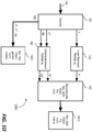
- FIG. 1C illustrates example encoder-side codec architecture 180, which may be implemented with one or more computing processors in an upstream video encoder, etc.
- the input images (117) of the high dynamic range after the post-production editing (115) may comprise, or may be further converted into, codewords in any of a variety of color spaces in any of a variety of sampling format.
- the input images (117) are represented in the EDR domain (145) in a Rec. 2020 YCbCr PQ domain in a 4:2:0 sampling format, and comprise luma codewords (denoted as "Y” in a single luma channel) and chroma codewords (denoted as "Cr” and "Cb” in two chroma channels). It should be noted that Rec.
- YCbCr PQ domain represents only one of many possible choices for an input format/domain in which the input images (117) may be represented. Examples of possible choices of input formats/domains may include, but are not necessarily limited to only, any of: YCbCr-PQ in Rec. 2020, ICtCp color space, DCI P3, or other color formats/domains.
- ICtCp color space and hybrid-log gamma (HLG) signal parameters are described in the ITU-R Report BT. 2390-0 (2016), " High dynamic range television for production and international programme exchange ".
- the reference tone-mapped images (117-1) of the relatively narrow dynamic range after the post-production editing (115) may comprise, or may be further converted into, codewords in any of a variety of color spaces in any of a variety of sampling format.
- the reference tone-mapped images (117-1) are represented in the reshaped domain (152) in an YCbCr color space (e.g., Rec. 709, P3, Rec.
- YCbCr represents only one of many possible choices for a format/domain in which the reference tone-mapped images (117-1) may be represented. Examples of possible choices of formats/domains may include, but are not necessarily limited to only, any of: Rec. 709, YCbCr gamma, Rec. 709 HLG, P3 HLG, or other color formats/domains.
- Forward reshaping as performed by the forward reshaping block (150) in generating the forward reshaped images (182) plays a relatively important role in ensuring that the input images of the high dynamic range (e.g., EDR, etc.) are efficiently compressed into the forward reshaped images (182) of the relatively narrow dynamic range (e.g., Rec. 709, SDR, etc.) in the reshaped domain (152), while at the same time ensuring that the forward reshaped images (182) are of the (e.g., near) production-quality that is directly viewable on a display device of the relatively narrow dynamic range. That way, the first specific artistic intent embodied in creating the reference tone-mapped images (117-1) after the post-production editing (115) is preserved relatively intact in the forward reshaped images (182) of the relatively narrow dynamic range.
- the input images of the high dynamic range e.g., EDR, etc.
- the relatively narrow dynamic range e.g., Rec. 709, SDR, etc.
- the forward reshaping as performed by the forward reshaping block (150) should be reversible or invertible, thereby allowing the forward reshaped images (182) to be backward reshaped (or to be reshaped back) into backward reshaped images (e.g., 132 of FIG. ID) of the high dynamic range (e.g., in the EDR domain, in an YCbCr-PQ domain, in an IPTPQ (ICtCp), etc.).
- the backward reshaped images (132) represent the reconstructed images (132) that are identical to, or relatively closely approximate, the input images (117) in the EDR domain (145). That way, the second specific artistic intent embodied in creating the input images (117) after the post-production editing (115) is also preserved relatively intact in the reconstructed images (132) of the high dynamic range.
- the forward reshaping block (150) comprises a luma forward reshaping block (162) to forward reshape the luma codewords (Y) of the input images (117) in the EDR domain (145) into forward reshaped luma codewords (denoted as "Y f ") of the forward reshaped images (182) in the reshaped domain (152) that approximate tone-mapped luma codewords of the reference tone-mapped images (117-1).
- the luma forward reshaping block (162) may be specifically configured to avoid banding artifacts and to improve compression efficiency.
- a method used by the luma forward reshaping block (162) to reshape luma codewords may make use of a (e.g., single-channel) luma forward reshaping function generated based on a histogram-based optimization algorithm.
- CAQ content-based quantization
- a color space and/or color gamut of a reference display e.g., 125, etc.
- another reference display e.g., 125-1, etc.
- the forward reshaping block (150) also needs to address the chroma reshaping issue.
- the forward reshaping block (150) comprises a chroma forward reshaping block (165) to forward reshape the chroma codewords (Cr and Cb).
- the chroma forward reshaping block (165) may implement a method to reshape chroma codeword (Cb and Cr) that is different from the (separate) single-channel method used by the luma forward reshaping block (162) to reshape luma codewords (Y).
- the method used by the chroma forward reshaping block (165) to reshape chroma codewords may be based on a multivariate multi-regression (MMR) -based algorithm that supports multiple-channel (or cross-channel) reshaping.
- MMR multivariate multi-regression
- the chroma forward reshaping block (165) receives the chroma codewords (Cr and Cb) of the input images (117), the chroma codewords (Cr and Cb) of the reference tone-mapped images (117-1), and downsampled luma codewords of the input images (117), as input.
- the input as received by the chroma forward reshaping block (165) may be mapped by the chroma forward reshaping block (165) into forward reshaped chroma codewords (denoted as "Cr f " and "Cb f ”) of the forward reshaped images (182) in the reshaped domain (152).
- forward reshaped chroma codewords denoted as "Cr f " and "Cb f ”
- Some examples of MMR-based chroma reshaping are described in U.S. Provisional Application No. 62/312,450 (or the '450 application), filed on March 23, 2016, entitled “Encoding and Decoding Reversible Production-Quality Single-Layer Video Signals" by Guan-Ming Su et al.
- the forward reshaping block (150) is configured to generate a (e.g., single-channel) luma backward reshaping function that can be delivered with the forward reshaped images (182) to a downstream video decoder as illustrated in FIG. 1D .
- the luma backward reshaping function may be used by the video decoder to backward reshape luma codewords of the forward reshaped images (182) into luma codewords of backward reshaped images (e.g., 132 of FIG. 1D , etc.).
- the forward reshaping block (150) comprises a chroma backward reshaping mapping generator (170) - which is to use the chroma codewords (Cr and Cb) of the input images (117), the forward reshaped chroma codewords (Cr f and Cb f ) of the forward-reshaped images (182), and downsampled forward reshaped luma codewords generated by downsampling the forward reshaped luma codewords (Y f ) of the forward-reshaped images (117), as input, to generate a chroma backward reshaping mapping that can be delivered with the forward reshaped images (182) and the luma backward reshaping function to a downstream video decoder as illustrated in FIG.
- a chroma backward reshaping mapping generator (170) - which is to use the chroma codewords (Cr and Cb) of the input images (117), the forward reshaped chrom
- the chroma backward reshaping mapping may be used by the video decoder to backward reshape chroma codewords of the forward reshaped images (182) into chroma codewords of backward reshaped images (e.g., 132 of FIG. 1D , etc.).
- operational parameters defining/specifying the luma backward reshaping function and the chroma backward reshaping mapping may be included as backward mapping metadata in image metadata to be encoded with the forward reshaped images (182) by a compressor (167) into the coded bit stream (122).
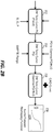
- FIG. 1D illustrates example decoder-side codec architecture 185, which may be implemented with one or more computing processors in a downstream video decoder, etc.
- the coded bit stream (122) may be decoded by a decompressor 172 into the decoded images, which may be the same as or similar to the forward reshaped images (182) subject to coding errors, quantization errors, etc., introduced in compression/decompression processes and comprise the luma forward reshaped codewords (Y f ) and the chroma forward reshaped codeword (Cr f and Cb f ).
- the forward reshaped images (182) with little or no changes can be directly rendered on a display device such as the first target display (140-1) that supports the relatively narrow dynamic range.
- a display device such as the first target display (140-1) that supports the relatively narrow dynamic range.
- the forward reshaped images (182) are generated to relatively closely approximate the reference tone-mapped images (117-1) after the post-production editing (115), the forward reshaped images (182) are expected to preserve to the specific artistic intent embodied in creating the reference tone-mapped images (117-1).
- the forward reshaped images (182) of the relatively narrow dynamic range, as decoded from the coded bit stream (122), may be further backward reshaped into the backward reshaped images (132) of the high dynamic range.
- a luma backward reshaping block 175 may be configured to apply the luma backward reshaping function as defined/specified in the backward reshaping metadata that is carried with the encoded forward reshaped images in the coded bit stream (122) to the luma forward reshaped codewords (Y f ) as input to generate luma backward reshaped codewords (Y b ) of the backward reshaped images (132) as output.
- a chroma backward reshaping block 190 may be configured to apply the chroma backward reshaping mapping as defined/specified in the backward reshaping metadata that is carried with the encoded forward reshaped images in the coded bit stream (122) to the chroma forward reshaped codewords (Cr f and Cb f ) and downsampled luma forward reshaped codewords generated by downsampling the luma forward reshaped codewords (Y f ) as input to generate chroma backward reshaped codewords (Cr b and Cb b ) of the backward reshaped images (132) as output.
- YCbCr-PQ in Rec. 2020 represents only one of many possible choices for an output format/domain in which the reconstructed images (132) may be represented. Examples of possible choices of output formats/domains may include, but are not necessarily limited to only, any of: YCbCr-PQ in Rec. 2020, IPTPQ (ICtCp), DCI P3, or other color formats/domains. It should also be noted that the reconstructed images (132) may be further transformed into an output format/domain that may or may not be the same as an input format/domain in which the input images (117) are represented.
- the backward reshaped images (132) with little or no changes can be directly rendered on a display device such as the display device (140-2) that supports the high dynamic range.
- a display device such as the display device (140-2) that supports the high dynamic range.
- the backward reshaped images (132) are generated to be identical or relatively closely approximate the input images (117) after the post-production editing (115), the backward reshaped images (132) are expected to preserve to the specific artistic intent embodied in creating the input images (117).
- Input images (e.g., 117, an EDR video signal, etc.) of a high dynamic range can be forward reshaped to forward reshaped images (e.g., 182, a "second grade" in block 204, an SDR video signal, etc.) of a relatively narrow dynamic range.
- forward reshaping operations that forward reshape the input images (117) into the forward reshaped images comprises (1) luma forward reshaping operations that forward reshape luma codewords of the input images (117) to luma codewords of the forward reshaping images, and (2) chroma forward reshaping operations that forward reshape chroma codewords of the input images (117) to chroma codewords of the forward reshaped images.
- the luma forward reshaping operations are based at least in part on a luma forward reshaping function, whereas the chroma forward reshaping operations are based at least in part on a chroma forward reshaping mapping.
- the luma forward reshaping function and/or the chroma forward reshaping mapping may be adjustable by adjusting luma mapping parameters and/or chroma mapping parameters to different parameter values.
- Example luma mapping parameters may include, but are not necessarily limited to only, any of: Lift/Gain/Gamma (LGG), Slope/Offset/Power (SOP), etc.
- Luma mapping parameters as described herein may be employed to adjust the luma forward reshaping function (or luma forward reshaping curve) in a range of luma codewords globally or locally.
- the entire range of luma codewords as represented in the input images (117) may be logically divided into multiple regions such as highlight regions, dark regions, mid-tone regions, other regions, etc.
- the luma mapping parameters may be varied among different combinations of parameter values for the purpose of generating different numbers, different densities, etc., of codewords available in these regions in the entire range of luma codewords.
- Example chroma mapping parameters may include, but are not necessarily limited to only, any of: scaling factors, mapping control parameters, etc. Chroma mapping parameters as described herein may be employed to adjust the chroma forward reshaping mapping globally or locally. For example, the chroma mapping parameters may be varied in one or more value ranges for the purpose of controlling distortions, color saturations, etc., in the forward reshaped images.
- FIG. 2A illustrates an example luma-look matching process in which optimized parameter values for luma mapping parameters are determined for forward reshaping luma codewords of the input images (117) to luma codewords of optimized forward reshaped images (182).
- Luma-look matching of FIG. 2A may be performed by one or more computing devices (e.g., coding block (120), luma forward reshaping block (162), etc.) on a frame basis, a Group of Pictures (GOP) basis, a scene basis, a multi-scene basis, etc.
- coding block 120
- luma forward reshaping block (162) etc.
- GOP Group of Pictures
- 2A may also be performed to determine/select optimized parameter values for chroma mapping parameters by one or more computing devices (e.g., coding block (120), luma forward reshaping block (162), etc.) on a frame basis, a Group of Pictures (GOP) basis, a scene basis, a multi-scene basis, etc.
- computing devices e.g., coding block (120), luma forward reshaping block (162), etc.
- each, some, or all of the luma mapping parameters may be tuned to different possible parameter values.
- a parameter value range for a luma mapping parameter may be discretized into a set of different discrete values.
- the luma mapping parameters may be set, varied or iterated through a plurality of combinations of candidate mapping parameter values.
- the luma mapping parameters as defined/specified by the plurality of combinations of candidate mapping parameter values may be used to define or specify a plurality of candidate luma forward reshaping functions.
- Each candidate luma forward reshaping function in the plurality of candidate luma forward reshaping functions may be defined or specified by a respective combination of candidate mapping parameter values in the plurality of combination of candidate mapping parameter values (which are tuned or varied in block 202).
- Luma-look characteristics are determined for a plurality of sets of candidate forward reshaped images (denoted as "second grade" in FIG. 2A ) that comprise candidate luma codewords forward reshaped from luma codewords of the input images (117) based on the plurality of candidate luma forward reshaping functions.
- Each set of candidate forward reshaped images in the plurality of sets of candidate forward reshaped images comprises candidate luma codewords forward reshaped from luma codewords of the input images (117) based on a respective candidate luma forward reshaping function in the plurality of candidate luma forward reshaping functions.
- the luma-look characteristics for the plurality of sets of candidate reshaped images may be compared with luma-look characteristics of the reference tone-mapped images (117-1), which is denoted as a "reference grade" in FIG. 2A .
- a specific candidate luma forward reshaping function may be selected/determined among the plurality of candidate luma forward reshaping functions as an optimized luma forward reshaping function, based on results of comparing the luma-look characteristics for the plurality of sets of candidate reshaped images ("second grade") and the luma-look characteristics of the reference tone-mapped images (117-1).
- the specific candidate luma forward reshaping function may be used to generate luma codewords of a specific set of candidate reshaped images in the plurality of sets of candidate reshaped images ("second grade").
- Luma-look characteristics of the specific set of candidate reshaped images may be determined to be the closest to the luma-look characteristics of the reference tone-mapped images (117-1 "reference grade").
- the luma-look matching process of FIG. 2A can be performed without actually generating full-fledge candidate forward reshaped images so long as the luma-look characteristics of the candidate forward reshaped images based on the candidate luma forward reshaping functions can be determined.
- the optimized luma forward reshaping function can be used to generate the optimized forward reshaped images (182) with similar luma look as compared with the reference tone-mapped images (117-1), while maintaining the reversibility of the optimized forward reshaped images (182).
- the optimized forward reshaped images (182) are reversible in that the optimized forward reshaped images (182) can be inversely mapped back to reconstructed images of the high dynamic range that are (e.g., completely, substantially, within quantization errors, etc.) approximate the input images (117).
- the optimized forward reshaped images (182) may be free of or may be of minimal clipped codeword regions.
- the optimized forward reshaped images (182) are generated based on the optimized luma forward reshaping function and thus match as closely as possible with the luma look(s) of the reference tone-mapped images (117-1) that are generated with a colorist's artistic intent.
- the reference tone-mapped images (117-1) may be created to support back compatibility, or to be rendered on a wide variety of display devices (e.g., SDR displays, etc.) of the relatively narrow dynamic range.
- the reference tone-mapped images (117-1) may be generated through content mapping (CM) operations controlled by a colorist.
- CM operations under the colorist may include, but are not necessarily limited to, any of: trim pass operations, the colorist's image manipulations, adjustments made with a different color space, etc.
- the reference tone-mapped images (117-1) comprise clipped codeword regions in which image details have been removed or significantly reduced in one or more of highlight regions, dark regions, etc., because of the trim pass operations, the colorist's image manipulations, the adjustments made with the different color space, etc.
- a video decoder it is not feasible or efficient for a video decoder to reconstruct images of the high dynamic range based on the reference tone-mapped images (117-1) with clipped codeword regions, even if the reference tone-mapped images (117-1) were delivered in the coded bitstream (122) to the video decoder.
- the optimized forward reshaped images (182) as generated based on the optimized luma forward reshaping function, can be encoded in the code bitstream (122) and provided to downstream video decoders. Since the optimized forward reshaped images (182) have the same or similar luma look(s) of the reference tone-mapped images (117-1), the colorist's artistic intent in creating the reference tone-mapped images (117-1) is entirely or substantially preserved in the optimized forward reshaped images (182). At the same time, the optimized forward reshaped images (182) are entirely or substantially free of clipping relative to the reference tone-mapped images (117-1). Thus, the optimized forward reshaped images (182) can be used to generate high quality reconstructed images of the high dynamic range that closely approximate the input images (117).
- Multi-layer encoding e.g., enhancement-layer encoding
- the optimized forward reshaped images (182) in the base layer can be much less complicated with the optimized forward reshaped images (182) in the base layer than with the reference tone-mapped images (117-1) in the base layer.
- FIG. 2B illustrates an example process to generate a luma forward reshaping function 218 (e.g., a candidate luma forward reshaping function, etc.) based on combining a number of mapping functions (or relationships).
- a luma forward reshaping function 218 e.g., a candidate luma forward reshaping function, etc.
- a luma component of the i th pixel of the j th input image e.g., one of the input images (117), an EDR picture, etc.
- a luma component of the i th pixel of the j th reference tone-mapped image e.g., one of the reference tone-mapped images (117-1), an SDR picture, etc.
- the mapping functions used to derive the luma forward reshaping function (218) may include a tone mapping function T ( ⁇ ) (denoted as "DM Tone Curve PQ (Fixed)" in FIG. 2B or 212 of FIG. 2B ) in a PQ domain.
- T ( ⁇ ) a tone mapping function
- the tone mapping function T ( ⁇ ) may be tuned or varied by incorporating a tone mapping modification function f (.) with luma mapping parameters t into a modified tone mapping function 214 (denoted as "DM Tone Curve PQ" in FIG. 2B ).
- Example tone mapping modification functions may include, but are not necessarily limited to only, any of: sigmoid curves, gamma curves, analytical curves, non-analytical curves, power functions, S-curves, etc.
- the tone mapping modification function f (.) and/or the luma mapping parameters t may be tuned or varied on a frame basis, a Group of Pictures (GOP) basis, a scene basis, a multi-scene basis, etc.
- the luma mapping parameters used in the tone mapping modification function f (.) to tune or vary the tone mapping function T ( ⁇ ) may, but are not necessarily limited to only, be SOP parameters.
- t [ slope offset power ] .
- the modified luma component y ⁇ ji t is essentially derived based on the modified tone mapping function 214 (denoted as "DM Tone Curve PQ" in FIG. 2B ) that combines the tone mapping relationship T ( ⁇ ) and the tone mapping modification function f ( ⁇ , ⁇ ).
- the modified luma component y ⁇ ji t can be converted to a luma component y ji t for a target display such as the second reference display (125-1) based on an EOTF (denoted as g ( ⁇ )) specific to the target display.
- the target display may be associated with one of: Rec. 709, YCbCr gamma, Rec. 709 HLG, P3 HLG, or other color formats/domains.
- the EOTF g ( ⁇ ) may represent a dynamic range transformation that compress a (e.g., full, a relatively large, etc.) dynamic range capable of being perceived by the HVS to an SMPTE range.
- the luma component y ji t may be represented as an integer between [0 2 BL_bit_depth_ 1].
- the luma component y ji t is essentially derived based on a second modified tone mapping function 216 (denoted as "DM Tone Curve Gamma/PQ/HLG" in FIG. 2B ) that combines the tone mapping relationship T ( ⁇ ) , the tone mapping modification function f ( ⁇ , ⁇ ), and the EOTF g ( ⁇ ).
- a CAQ curve comprising bit depths computed based on noise measurements of the j th input image of the high dynamic range may be combined with the second modified tone mapping function (216) to generate the luma forward reshaping function (218).
- the bit depths from the CAQ curve may be used in place of the bit depths represented by the second modified tone mapping function (216) for the purpose of generating the luminance forward reshaping function (218).
- a desired goal is to adjust parameter values of t so that the luma component y ji t generated by the luma forward reshaping curve (28) can have as similar look as the luma component ⁇ s ji ⁇ of the reference tone-mapped images (117-1).
- an approach for identifying an optimized luma forward reshaping function is as follows: (1) applying the luma forward reshaping function (218) with the luma mapping parameters t to map the luma component v ji of every pixel of the j th input image (e.g., one of the input images (117), an EDR picture, etc.) into the luma component y ji t of every pixel of the j th mapped image, (2) calculating a distance/similarity based on differences between the luma component ⁇ s ji ⁇ of the reference tone-mapped images (117-1) and the luma component y ji t of every pixel of the j th mapped image, (3) repeating the foregoing steps (1) and (2) for all possible combinations of candidate parameter values of the luma mapping parameters t , and (4) selecting the best parameter values for the luma mapping parameters t , where the best parameter values correspond to the minimum of the distance or the maximum
- the luma forward reshaping function (218) with the best parameter values for t are then chosen to be the optimized luma forward reshaping function to forward reshape the j th input image into the j th forward reshaped image.
- techniques as described herein provide an efficient way (e.g., in terms of computational efficiency, coding efficiency, etc.) to search optimal (e.g., the best, etc.) parameter values for luma mapping parameters (e.g., SOP, LGG, etc.) that can be used to generate the optimized forward reshaped images (182) that have the closest luma look to that of the reference tone-mapped images (117-1).
- the optimal parameter values for the luma mapping parameters can be selected from among all different combinations of candidate parameter values such that the optimal parameter values correspond to a specific combination of parameter values with the best score in the distance/similarity measurement among scores in the distance/similarity measurements for the different combinations of candidate parameter values.
- luma-look characteristics of an image, a GOP, a scene, multiple scenes, etc. may be represented a luma histogram of the image, the GOP, the scene, the multiple scenes, etc.
- luma histogram refers to a histogram that is built based on a distribution of luma components of an image, a GOP, a scene, multiple scenes, etc.
- One way to determine whether luma looks of a first image (e.g., a mapped image, an optimized forward reshaped image, etc.) and a second image (e.g., a reference tone-mapped image, etc.) - both of which may be of the same dynamic range (e.g., the relatively narrow dynamic range, etc.) - are similar is to determine whether luma histograms of the first image and the second image are similar.
- similar luma looks of the images can be measured or represented by similar luma value distributions (or similar pixel counts over a common or substantially overlapping luma codeword range) as captured by the luma histograms of the images.
- a score in the distance/similarity measurement between a mapped image and the reference tone-mapped image may be computed based on a comparison of a luma histogram of the mapped image and a luma histogram of the reference tone-mapped image.
- the luma mapping parameters with the optimal parameter values as determined based on the luma histograms may be used to generate an optimized luma forward reshaping function that forward reshapes the reference tone-mapped image into an optimized forward reshaped image.
- the optimized forward reshaped image generated under techniques as described herein preserves image details for reversibility, while maintaining the colorist's artistic intent expressed in the reference tone-mapped image.
- a luma histogram of the mapped image might be obtained by applying to the luma components ⁇ v ji ⁇ of the input image all operations, T ( ⁇ ), f( ⁇ , t ), and g ( ⁇ ) to obtain the luma components y ji t of the mapped image and then building the luma histogram of the mapped image based on the luma components y ji t .
- this approach of building the luma histogram of the mapped image could be computation intensive.
- the histogram-based luma-look matching process may be divided into three major steps: (1) histogram preparation: prepare a first histogram of an input image (e.g., one of the input images (117), etc.) of the high dynamic range and a second histogram of a reference tone-mapped image (e.g., one of the reference tone-mapped images (117-1), etc.) of the relatively narrow dynamic range that corresponds to the input image of the high dynamic range, (2) histogram transfer: instead of calculating a histogram of a mapped image based on mapped pixel values of the mapped image, convert the first histogram via the luma forward reshaping function (218) with a combination of candidate parameter values for the luma mapping parameters (e.g., SOP, LGG, etc.) to a
- the three major steps of histogram preparation, histogram transfer and histogram matching as enumerated above may be carried in a series of detailed steps as follows.
- valid spatial regions may be established/identified in the reference tone-mapped image and the input image (e.g., 302 of FIG. 3A , etc.) by excluding certain spatial regions such as letterbox areas from the reference tone-mapped image and the input image (302).
- the valid spatial regions of the reference tone-mapped image and the input image (302) may be used in place of the reference tone-mapped image and the input image (302) to avoid matching between potentially numerous black pixels.
- Step 2 of the histogram-based luma look matching process a luma histogram of the reference tone-mapped image is prepared or built based on the luma components ⁇ s ji ⁇ of the reference tone-mapped image.
- N For the relatively narrow dynamic range of the reference tone-mapped images (117-1).
- N can be as large as the total number of codewords available in the relatively narrow dynamic range (e.g., 1024 for a 10-bit base layer codeword space, etc.).
- N can be set to a much smaller value (e.g., 256, a fraction of the total number of codewords available in the relatively narrow dynamic range, etc.) by trading off some accuracy.
- the luma histogram h n s of the reference tone-mapped image is built.
- luma histograms of the reference tone-mapped images (117-1) can be built at one of various levels, such as for an image, a GOP, a scene, multiple scenes, etc.
- the frame index j has been dropped from expressions (4) and (5) above for simplicity.
- Step 3 of the histogram-based luma look matching process a luma histogram (e.g., 304 of FIG. 3A , etc.) of the input image (302) is prepared or built based on the luma components ⁇ v ji ⁇ of the input image (302).
- the luma histogram (304), h m v , of the input image (302) is built.
- luma histograms including but not limited to the luma histogram (304) of the input images (117) can be built at one of various levels, such as for an image, a GOP, a scene, multiple scenes, etc.
- the frame index j has been dropped from expressions (6) and (7) above for simplicity.
- the luma histogram (304) of the input image (302) is to be transferred to luma histograms (e.g., one of which may 306 of FIG 3A , etc.) of multiple mapped images.
- certain quantization-like operations may be performed as a part of transferring the luma histogram (304) of the input image (302) to the luma histograms (e.g., 306, etc.) of the multiple mapped images.
- a higher precision for the luma histogram (304) of the input image (302) in the high dynamic range, as compared with the luma histograms (e.g., 306, etc.) of the mapped images in the relatively narrow dynamic range may be used.
- Step 4 of the histogram-based luma look matching process a representative point is selected in each bin of the luma histogram (304) of the input image (302).
- a very high precision of mapping the luma components v ji e.g., represented in a look-up table or LUT, etc.
- the total number of calculations for mapping the luma components v ji of the input image (302) to the luma components of the mapped images (e.g., 306, etc.) may be proportional to the number of entries of the LUT.
- M different v ji value may be selected to respectively represent luma components of M different bins of the luma histogram (304) of the input image (302).
- the output of the luma forward reshaping function (e.g., 218 of FIG. 2B or FIG. 3A , etc.), as given by g ( f ( T ( v m ) , t ) in expression (9), is already in the relatively narrow dynamic range (e.g., 10-bit base layer, an SDR (BL) bit depth, etc.) of the mapped images. Since luma components of the mapped images are to be grouped into N bins, it is relatively efficient for histogram transfer as described herein to have the mapped point, as determined by the combined function LUT t , to be translated into an index value between 0 and N-1.
- a round operation such as a quantization by ⁇ is performed in expression (9) on the output of the luma forward reshaping function (218) (as given by g ( f ( T ( v m ) , t ) in expression (9)) to obtain the mapped point, which can then be translated or used to determine an index value n corresponding to the n th bin of the N bins of the luma histogram (e.g., 306, etc.) of the mapped image(s).
- Step 6 of the histogram-based luma look matching process bins in the luma histogram (304) of the input image (302) that are mapped to the same mapped point or the same bin of the luma histogram (306) of the mapped image are combined into the same bin of the luma histogram (306) of the mapped image.
- the bins h ⁇ n t of the luma histogram (306) of the mapped image may be initialized 0 before mapping/combining the bins of the luma histogram (306) of the input image into the bins h ⁇ n t of the luma histogram (306) of the mapped image.
- v m in each bin of the luma histogram (304) of the input image (302), the corresponding mapped value y m t is determined in expression (9).
- the luma histogram (304) of the input image (302) is transferred or mapped to the luma histogram (306) of the mapped image that correspond to any given set of candidate parameter values for the luma mapping parameters t , while avoiding actually generating the mapped image and/or while avoiding actually generating the luma components of the mapped image.
- Steps 1-4 as detailed above are independent of the luma mapping parameters t. Thus, these steps may be done once in some embodiments. Steps 5 and 6 may be repeated for different combinations of candidate parameter values for the luma mapping parameters t that are used in the luma forward reshaping function (218).
- a score in the distance/similarity measurement between two histograms h n s and h ⁇ n t may be defined as follows: SIM h ⁇ n t h n s
- the problem for best matching luma looks can be formulated as an optimization problem to maximize the scores in the distance/similarity measurement by searching all feasible/possible combinations of candidate parameter values for the luma mapping parameters t , as follows: max t SIM h ⁇ n t h n s
- the minimal value of the pixel counts in the bin from the luma histograms h n s and h ⁇ n t is selected to be summed up on the right hand side (RHS) of expression (14).
- RHS right hand side
- FIG. 2C illustrates an example luma-look matching process in which optimized parameter values for luma mapping parameters are determined for forward reshaping luma codewords of the input images (117) to luma codewords of optimized forward reshaped images (182).
- Luma-look matching of FIG. 2C may be performed by one or more computing devices (e.g., coding block (120), luma forward reshaping block (162), etc.) on a frame basis, a Group of Pictures (GOP) basis, a scene basis, a multi-scene basis, etc.
- a process e.g., MMR-based optimization process, etc. operating in conjunction with that of FIG.
- 2C may also be performed to determine/select optimized parameter values for chroma mapping parameters by one or more computing devices (e.g., coding block (120), chroma forward reshaping block (165), etc.) on a frame basis, a Group of Pictures (GOP) basis, a scene basis, a multi-scene basis, etc.
- computing devices e.g., coding block (120), chroma forward reshaping block (165), etc.
- the luma histograms of the reference tone-mapped image and the input image corresponding to the reference tone-mapped image are pre-calculated.
- the luma histogram h n s of the reference tone-mapped image may be obtained with reduced sample points N
- the luma histogram h m v of the input image may be obtained with reduced sample points M .
- the luma histogram h m v of the input image obtained with reduced sample points M is used to derive a luma histogram h ⁇ n t of a mapped image that comprises luma components forward reshaped from luma components of the input image using the luma forward reshaping function (218) with the current combination of parameter values for the loop.
- the luma histogram h ⁇ n t of the mapped image can be derived via histogram transfer as described herein without actually generating the mapped image and/or without actually generating luma components (and chroma components) of the mapped image.
- the luma histogram h ⁇ n t of the mapped image may be compared with the luma histogram h n s of the reference tone-mapped image.
- the comparison of the luma histograms h ⁇ n t and h n s may be performed using a score computed with expression (12).
- the current best found parameter values correspond to a previous combination of candidate parameter values that generates the best matching luma look of all the previous mapped images with all the previous combinations of candidate parameter values that have been repeated or iterated before the current combination of candidate parameter values.
- the current best found parameter values are updated to be the current combination of candidate parameter values in block 230.
- the current best found parameter values are not updated in block 230.
- the current best found parameter values are chosen to be optimal parameter values for the luma mapping parameters.
- the optimal parameter values for the luma mapping parameters are used in the luma forward reshaping function (218) to generate an optimized luma forward reshaping function to forward reshape the luma components of the input image (e.g., in the input images (117), etc.) into luma components of an optimized forward reshaped image (e.g., in the optimized forward reshaped images (182), etc.).
- Computational complexity for the histogram-based luma look matching process of FIG. 2C includes computational complexity of O( L ⁇ M ) for histogram transfer and similarity computation, where L is the number of all possible combinations of candidate parameter values for the luma mapping parameters and M is the number (e.g., M is 1024 while N is 256, etc.) of bins in the luma histogram of the input image of the high dynamic range.
- O the computational complexity for the histogram-based luma look matching process of FIG. 2C is much more efficient.
- the number of pixels ( P ) in UHD pictures/images can be as high as 8,294,400.
- the histogram-based luma look matching process of FIG. 2C is 8100 times more efficient than the pixel-based luma look matching process as shown in TABLE 1.
- an LUT such as used in expression (9) can be computation intensive.
- a further efficient way as shown in TABLE 4 below is to separate the LUT into (1) a first part that represents a fixed part (e.g., mappings from PQ to gamma or from PQ to HLG, etc.) independent of the luma mapping parameters, and (2) a second part that is dependent on the luma mapping parameters.
- Computations for the first part can be performed only once, while computation for the second part may be repeated for different possible combinations of candidate parameter values for the luma mapping parameters.
- the computation for the second part can also be sped up. For example, an entire full precision LUT used in the second part may or may not be generated.
- Computational complexity of the simplified process as shown in TABLE 4 based on a coarse precision LUT is O(L ⁇ M).
- the simplified process as shown in TABLE 4 generates a further 64 times faster speed as compared with computational complexity O(L ⁇ 2 EDR_bit_depth ) based on the full precision LUT.
- FIG. 3B illustrates example luma histograms.
- a luma histogram of a reference tone-mapped image which is created with a colorist's artistic intent, is represented by a first histogram plot 308.
- a luma histogram of a mapped image which is created with the luma forward reshaping function (e.g., with all SOP parameters set to 0, etc.) without any adjustment using the luma mapping parameters (e.g., SOP, LGG, etc.), is represented by a second histogram plot 310. As shown in FIG.
- the luma histogram of the mapped image created with the luma forward reshaping function without any adjustment using the luma mapping parameters is dissimilar to the luma histogram of the reference tone-mapped image created with the colorist's artistic intent. For example, such a mapped image may look overall dark as compared with the reference tone-mapped image.
- the best parameter values may be found among all possible combinations of candidate parameter values through a combination of histogram preparation, histogram transfer and histogram similarity determination.
- the luma histograms 308 and 312 of the reference tone-mapped image and the best luma look matching mapped image created with the luma forward reshaping function using the luma mapping parameters have much better similarity than the luma histograms 310 and 312 of the reference tone-mapped image and the mapped image created with the luma forward reshaping function without any adjustment using the luma mapping parameters.
- the luma look in some luma codeword regions may be relatively important as compared with some other luma codeword regions.
- the former luma codeword regions may be identified in images as described herein, and may be assigned with higher weighting factor values in the histogram-based luma look matching process.
- a score in the distance/similarity measurement between two histograms h n s and h ⁇ n t may be defined as follows: SIM h ⁇ n t h n s w n
- the problem for best matching luma looks can be formulated as an optimization problem to maximize the scores in the distance/similarity measurement by searching all feasible/possible combinations of candidate parameter values for the luma mapping parameters t , as follows: max t SIM h ⁇ n t h n s w n
- peaks in the histograms may be identified or detected after the histograms are applied with a medium filter.
- a search for the best parameter values for the luma mapping parameters may be conducted among all candidate combinations of parameter values for the luma mapping parameters using scores that are computed based on subsets of bins in all the bins of the entire histograms, where the subsets of bins correspond to the detected peaks in the histograms.
- spatial registration may be used to avoid matching wrong pairs of peaks of the histograms.
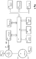
- FIG. 4A illustrates an example process flow according to an embodiment of the present invention.
- one or more computing devices or components e.g., an encoding device/module, a transcoding device/module, a decoding device/module, a tone mapping device/module, a graphic blending device, an image blending device/module, a media device/module, etc. may perform this process flow.
- an image processing device e.g., coding block (120), etc.
- the luma histogram over the high dynamic range is generated based on one or more input images of the high dynamic range.
- Each luma histogram in the plurality of luma histograms over the relatively narrow dynamic range is generated based at least in part on the luma histogram over a high dynamic range and a respective combination of candidate parameter values in the plurality of combinations of candidate parameter values for the one or more luma mapping parameters.
- the image processing device compares the plurality of luma histograms over the relatively narrow dynamic range with a luma histogram of one or more reference tone-mapped images over the relatively narrow dynamic range.
- the image processing device selects, based on results of comparing the plurality of luma histograms with the luma histogram of the one or more reference tone-mapped images, a specific combination of candidate parameter values from among the plurality of combinations of candidate parameter values.
- the image processing device uses a luma forward reshaping function with the one or more luma parameter values that are set to the specific combination of candidate parameter values to forward reshape luma components of the one or more input images into luma components of one or more forward reshaped images over the relatively narrow dynamic range.
- the image processing device transmits the one or more forward reshaped images to one or more recipient devices.
- the luma forward reshaping function maps the one or more input images into the one or more forward reshaped images free of clipping.
- the image processing device is further configured to perform: generating backward reshaping metadata that is to be used by the one or more recipient devices to generate a luma backward reshaping function that corresponds to an inverse of the luma forward reshaping function with the one or more luma parameter values set to the specific combination of candidate parameter values; transmitting the one or more forward reshaped images with the backward reshaping metadata to the one or more recipient devices; etc.
- the image processing device is further configured to perform: deriving a chroma forward reshaping mapping for predicting chroma codewords of the one or more forward reshaped images, the chroma forward reshaping mapping being generated using chroma codewords of the one or more reference tone-mapped images as a prediction target; generating a portion of backward reshaping metadata that is to be used by the one or more recipient devices to generate a chroma backward reshaping mapping; transmitting the one or more forward reshaped images with the backward reshaping metadata to the one or more recipient devices; etc.
- the chroma forward reshaping mapping is generated based on a multivariate multi-regression (MMR) -based algorithm that supports multiple-channel reshaping.
- MMR multivariate multi-regression
- the luma forward reshaping function is derived as a combination of one or more of: luma tone-mapping functions, luma tone-mapping modification functions, electro-optical transfer functions, content-adaptive-quantized functions generated based on noise measurements of the one or more input images, etc.
- the one or more luma mapping parameters comprise one or more of: slope, offset and power (SOP) parameters; lift, gain and gamma (LGG) parameters; other luma mapping parameters; etc.
- SOP slope, offset and power
- LGG lift, gain and gamma
- one or both of the one or more input images or the one or more reference tone-mapped images are generated in post-production editing.
- the one or more forward reshaped images are encoded in a video signal of the relatively narrow dynamic range; the backward reshaping metadata is carried in the video signal as metadata separate from the one or more forward reshaped image.
- the video signal excludes one or both of the one or more input images or the one or more reference tone-mapped images.
- the one or more input images are represented in a different color space than that in which the one or more reference tone-mapped images are represented.
- the one or more input images are formatted in a different sampling format than that in which the one or more reference tone-mapped images are formatted.
- At least one of the one or more input images or the one or more reference tone-mapped images are represented in one of: an IPT PQ (ICtCp) color space, an YCbCr color space, an RGB color space, a Rec. 2020 color space, a Rec. 709 color space, an extended dynamic range (EDR) color space, a gamma/HLG/PQ color space, a standard dynamic range (SDR) color space, etc.
- IPT PQ IPT PQ
- the one or more forward reshaped images are represented in a reshaped domain; the reshaped domain is of a bit depth of one of 8, 9, 10, 11+ bits, etc.
- the one or more input images are represented in a pre-reshaped domain; the pre-reshaped domain is of a bit depth of one of 10, 11, 12, 13, 14, 15+ bits, etc.
- one or both of the one or more input images or the one or more reference tone-mapped images are created based a video professional's artistic intent.
- FIG. 4B illustrates an example process flow according to an embodiment of the present invention.
- one or more computing devices or components e.g., an encoding device/module, a transcoding device/module, a decoding device/module, a tone mapping device/module, a graphic blending device, an image blending device/module, a media device/module, etc.
- an image processing device e.g., decoding block (130), etc. constructs, based on backward reshaping metadata received with one or more forward reshaped images of a relatively narrow dynamic range, a luma backward reshaping function.
- the luma backward reshaped function represents an inverse of a luma forward reshaping function with one or more luma parameter values that are set to a specific combination of candidate parameter values.
- the luma forward reshaping function with the one or more luma parameter values set to the specific combination of candidate parameter values is used to forward reshape luma components of the one or more input images over a high dynamic range into luma components of the one or more forward reshaped images over the relatively narrow dynamic range.
- the specific combination of candidate parameter values is selected based on results of comparing a plurality of luma histograms with a luma histogram of one or more reference tone-mapped images over the relatively narrow dynamic range, from among a plurality of combinations of candidate parameter values.
- the plurality of luma histograms over the relatively narrow dynamic range is generated based at least in part on (a) a luma histogram over the high dynamic range and (b) the plurality of combinations of candidate parameter values for the one or more luma mapping parameters.
- the luma histogram over the high dynamic range is generated based on one or more input images of the high dynamic range.
- each luma histogram in the plurality of luma histograms over the relatively narrow dynamic range is generated based at least in part on the luma histogram over a high dynamic range and a respective combination of candidate parameter values in the plurality of combinations of candidate parameter values for the one or more luma mapping parameters.
- the image processing device applies the luma backward reshaping function to luma components of the one or more forward reshaped images to generate luma codewords of one or more reconstructed images of the high dynamic range that approximate one or more input images of the high dynamic range.
- the image processing device causes the one or more reconstructed images to be rendered with a display device.
- the image processing device is further configured to perform: deriving, based on the backward reshaping metadata, a chroma backward reshaping mapping for predicting chroma codewords of the one or more reconstructed images; applying the chroma backward reshaping function to chroma components of the one or more forward reshaped images to generate chroma codewords of the one or more reconstructed images; etc.
- the chroma backward reshaping mapping is generated based on a multivariate multi-regression (MMR) -based algorithm that supports multiple-channel reshaping.
- MMR multivariate multi-regression
- the one or more forward reshaped images are decoded from a video signal of the relatively narrow dynamic range; the backward reshaping metadata is carried in the video signal as metadata separate from the one or more forward reshaped image.
- the video signal excludes one or both of the one or more input images or one or more reference tone-mapped images which the one or more forward reshaped images approximate.
- the one or more reconstructed images are represented in a different color space than that in which the one or more forward reshaped images are represented.
- the one or more reconstructed images are formatted in a different sampling format than that in which the one or more forward reshaped images are formatted.
- At least one of the one or more reconstructed images or the one or more forward reshaped images are represented in one of: an IPT PQ (ICtCp) color space, an YCbCr color space, an RGB color space, a Rec. 2020 color space, a Rec. 709 color space, an extended dynamic range (EDR) color space, a gamma color space, an HLG color space, a PQ color space, a standard dynamic range (SDR) color space, etc.
- IPT PQ IPT PQ
- the one or more forward reshaped images are represented in a reshaped domain; the reshaped domain is of a bit depth of one of 8, 9, 10, 11+ bits, etc.
- the one or more reconstructed images are represented in a pre-reshaped domain; the pre-reshaped domain is of a bit depth of one of 10, 11, 12, 13, 14, 15+ bits, etc.
- a computing device such as a display device, a mobile device, a set-top box, a multimedia device, etc., is configured to perform any of the foregoing
- an apparatus comprises a processor and is configured to perform any of the foregoing methods.
- a non-transitory computer readable storage medium storing software instructions, which when executed by one or more processors cause performance of any of the foregoing methods.
- a computing device comprising one or more processors and one or more storage media storing a set of instructions which, when executed by the one or more processors, cause performance of any of the foregoing methods.
- Embodiments of the present invention may be implemented with a computer system, systems configured in electronic circuitry and components, an integrated circuit (IC) device such as a microcontroller, a field programmable gate array (FPGA), or another configurable or programmable logic device (PLD), a discrete time or digital signal processor (DSP), an application specific IC (ASIC), and/or apparatus that includes one or more of such systems, devices or components.
- IC integrated circuit
- FPGA field programmable gate array
- PLD configurable or programmable logic device
- DSP discrete time or digital signal processor
- ASIC application specific IC
- the computer and/or IC may perform, control, or execute instructions relating to the adaptive perceptual quantization of images with enhanced dynamic range, such as those described herein.
- the computer and/or IC may compute any of a variety of parameters or values that relate to the adaptive perceptual quantization processes described herein.
- the image and video embodiments may be implemented in hardware, software, firmware and various combinations thereof.
- Certain implementations of the invention comprise computer processors which execute software instructions which cause the processors to perform a method of the invention.
- processors in a display, an encoder, a set top box, a transcoder or the like may implement methods related to adaptive perceptual quantization of HDR images as described above by executing software instructions in a program memory accessible to the processors.
- the invention may also be provided in the form of a program product.
- the program product may comprise any non-transitory medium which carries a set of computer-readable signals comprising instructions which, when executed by a data processor, cause the data processor to execute a method of the invention.
- Program products according to the invention may be in any of a wide variety of forms.
- the program product may comprise, for example, physical media such as magnetic data storage media including floppy diskettes, hard disk drives, optical data storage media including CD ROMs, DVDs, electronic data storage media including ROMs, flash RAM, or the like.
- the computer-readable signals on the program product may optionally be compressed or encrypted.
- a component e.g. a software module, processor, assembly, device, circuit, etc.
- reference to that component should be interpreted as including as equivalents of that component any component which performs the function of the described component (e.g., that is functionally equivalent), including components which are not structurally equivalent to the disclosed structure which performs the function in the illustrated example embodiments of the invention.
- the techniques described herein are implemented by one or more special-purpose computing devices.
- the special-purpose computing devices may be hard-wired to perform the techniques, or may include digital electronic devices such as one or more application-specific integrated circuits (ASICs) or field programmable gate arrays (FPGAs) that are persistently programmed to perform the techniques, or may include one or more general purpose hardware processors programmed to perform the techniques pursuant to program instructions in firmware, memory, other storage, or a combination.
- ASICs application-specific integrated circuits
- FPGAs field programmable gate arrays
- Such special-purpose computing devices may also combine custom hard-wired logic, ASICs, or FPGAs with custom programming to accomplish the techniques.
- the special-purpose computing devices may be desktop computer systems, portable computer systems, handheld devices, networking devices or any other device that incorporates hard-wired and/or program logic to implement the techniques.
- FIG. 5 is a block diagram that illustrates a computer system 500 upon which an embodiment of the invention may be implemented.
- Computer system 500 includes a bus 502 or other communication mechanism for communicating information, and a hardware processor 504 coupled with bus 502 for processing information.
- Hardware processor 504 may be, for example, a general purpose microprocessor.
- Computer system 500 also includes a main memory 506, such as a random access memory (RAM) or other dynamic storage device, coupled to bus 502 for storing information and instructions to be executed by processor 504.
- Main memory 506 also may be used for storing temporary variables or other intermediate information during execution of instructions to be executed by processor 504.
- Such instructions when stored in non-transitory storage media accessible to processor 504, render computer system 500 into a special-purpose machine that is customized to perform the operations specified in the instructions.
- Computer system 500 further includes a read only memory (ROM) 508 or other static storage device coupled to bus 502 for storing static information and instructions for processor 504.
- ROM read only memory
- a storage device 510 such as a magnetic disk or optical disk, is provided and coupled to bus 502 for storing information and instructions.
- Computer system 500 may be coupled via bus 502 to a display 512, such as a liquid crystal display, for displaying information to a computer user.
- a display 512 such as a liquid crystal display
- An input device 514 is coupled to bus 502 for communicating information and command selections to processor 504.
- cursor control 516 is Another type of user input device
- cursor control 516 such as a mouse, a trackball, or cursor direction keys for communicating direction information and command selections to processor 504 and for controlling cursor movement on display 512.
- This input device typically has two degrees of freedom in two axes, a first axis (e.g., x) and a second axis (e.g., y), that allows the device to specify positions in a plane.
- Computer system 500 may implement the techniques described herein using customized hard-wired logic, one or more ASICs or FPGAs, firmware and/or program logic which in combination with the computer system causes or programs computer system 500 to be a special-purpose machine. According to one embodiment, the techniques as described herein are performed by computer system 500 in response to processor 504 executing one or more sequences of one or more instructions contained in main memory 506. Such instructions may be read into main memory 506 from another storage medium, such as storage device 510. Execution of the sequences of instructions contained in main memory 506 causes processor 504 to perform the process steps described herein. In alternative embodiments, hard-wired circuitry may be used in place of or in combination with software instructions.
- Non-volatile media includes, for example, optical or magnetic disks, such as storage device 510.
- Volatile media includes dynamic memory, such as main memory 506.
- Common forms of storage media include, for example, a floppy disk, a flexible disk, hard disk, solid state drive, magnetic tape, or any other magnetic data storage medium, a CD-ROM, any other optical data storage medium, any physical medium with patterns of holes, a RAM, a PROM, and EPROM, a FLASH-EPROM, NVRAM, any other memory chip or cartridge.
- Storage media is distinct from but may be used in conjunction with transmission media.
- Transmission media participates in transferring information between storage media.
- transmission media includes coaxial cables, copper wire and fiber optics, including the wires that comprise bus 502.
- transmission media can also take the form of acoustic or light waves, such as those generated during radio-wave and infra-red data communications.
- Various forms of media may be involved in carrying one or more sequences of one or more instructions to processor 504 for execution.
- the instructions may initially be carried on a magnetic disk or solid state drive of a remote computer.
- the remote computer can load the instructions into its dynamic memory and send the instructions over a telephone line using a modem.
- a modem local to computer system 500 can receive the data on the telephone line and use an infra-red transmitter to convert the data to an infra-red signal.
- An infra-red detector can receive the data carried in the infra-red signal and appropriate circuitry can place the data on bus 502.
- Bus 502 carries the data to main memory 506, from which processor 504 retrieves and executes the instructions.
- the instructions received by main memory 506 may optionally be stored on storage device 510 either before or after execution by processor 504.
- Computer system 500 also includes a communication interface 518 coupled to bus 502.
- Communication interface 518 provides a two-way data communication coupling to a network link 520 that is connected to a local network 522.
- communication interface 518 may be an integrated services digital network (ISDN) card, cable modem, satellite modem, or a modem to provide a data communication connection to a corresponding type of telephone line.
- ISDN integrated services digital network
- communication interface 518 may be a local area network (LAN) card to provide a data communication connection to a compatible LAN.
- LAN local area network
- Wireless links may also be implemented.
- communication interface 518 sends and receives electrical, electromagnetic or optical signals that carry digital data streams representing various types of information.
- Network link 520 typically provides data communication through one or more networks to other data devices.
- network link 520 may provide a connection through local network 522 to a host computer 524 or to data equipment operated by an Internet Service Provider (ISP) 526.
- ISP 526 in turn provides data communication services through the world wide packet data communication network now commonly referred to as the "Internet" 528.
- Internet 528 uses electrical, electromagnetic or optical signals that carry digital data streams.
- the signals through the various networks and the signals on network link 520 and through communication interface 518, which carry the digital data to and from computer system 500, are example forms of transmission media.
- Computer system 500 can send messages and receive data, including program code, through the network(s), network link 520 and communication interface 518.
- a server 530 might transmit a requested code for an application program through Internet 528, ISP 526, local network 522 and communication interface 518.
- the received code may be executed by processor 504 as it is received, and/or stored in storage device 510, or other non-volatile storage for later execution.
Landscapes
- Engineering & Computer Science (AREA)
- Multimedia (AREA)
- Signal Processing (AREA)
- Physics & Mathematics (AREA)
- General Physics & Mathematics (AREA)
- Theoretical Computer Science (AREA)
- Compression Or Coding Systems Of Tv Signals (AREA)
Claims (14)
- Verfahren zum Vorwärtsumformen von Luma-Komponenten eines Eingabebildes (117) eines ersten Dynamikbereichs, umfassend:Bereitstellen eines tonegemappten Referenzbildes (117-1) über einen zweiten Dynamikbereich, der dem Eingabebild (117) des ersten Dynamikbereichs entspricht, wobei der erste Dynamikbereich größer als der zweite Dynamikbereich ist;Bereitstellen einer Luma-Vorwärtsumformungsfunktion (162), um Luma-Komponenten eines Eingabebildes (117) eines ersten dynamischen Bereichs in Luma-Komponenten eines entsprechenden vorwärts umgeformten Bildes (182) über einen zweiten dynamischen Bereich, basierend auf einem oder mehreren Luma-Mapping-Parametern, vorwärtsumzuformen;Bereitstellen einer Vielzahl von Kombinationen von Kandidaten-Parameterwerten für einen oder mehrere Luma-Mapping-Parameter;Erzeugen eines Luma-Histogramms des Eingabebildes (117) über den ersten Dynamikbereich;Erzeugen eines Luma-Histogramms des tonegemappten Referenzbildes (117-1) über den zweiten Dynamikbereich;Erzeugen (402) einer Vielzahl von gemappten Luma-Histogrammen über den zweiten dynamischen Bereich durch Umwandeln, für jeden der bereitgestellten Kandidaten-Parameterwerte für den einen oder die mehrere Luma-Mapping-Parameter, des Luma-Histogramms des Eingabebildes (117) über den ersten dynamischen Bereich über die Luma-Vorwärtsumformungsfunktion (162) mit einer entsprechenden Kombination der bereitgestellten Kandidaten-Parameterwerte in ein entsprechendes gemapptes Luma-Histogramm über den zweiten dynamischen Bereich;Vergleichen (404) der Vielzahl von Luma-Histogrammen über den zweiten Dynamikbereich mit dem Luma-Histogramm des tonegemappten Referenzbildes über den zweiten Dynamikbereich;Auswählen (406), basierend auf den Ergebnissen des Vergleichens der Vielzahl von Luma-Histogrammen mit dem Luma-Histogramm des tonegemappten Referenzbildes (117-1), einer spezifischen Kombination von Kandidaten-Parameterwerten aus der Vielzahl von Kombinationen von Kandidaten-Parameterwerten;Verwenden (408) der Luma-Vorwärtsumformungsfunktion (162) mit einem oder mehreren Luma-Parameterwerten, die auf die spezifische Kombination von Kandidaten-Parameterwerten eingestellt sind, um Luma-Komponenten des Eingabebildes (117) in Luma-Komponenten des vorwärts umgeformten Bildes (182) über den zweiten Dynamikbereich vorwärts umzuformen;Erzeugen von Rückwärtsumformungs-Metadaten, die von dem einen oder den mehreren Empfängervorrichtungen verwendet werden sollen, um eine Luma-Rückwärtsumformungsfunktion (175) zu erzeugen, die einer Umkehrung der Luma-Vorwärtsumformungsfunktion (162) entspricht, wobei der eine oder die mehreren Luma-Parameterwerte auf die spezifische Kombination von Kandidaten-Parameterwerten eingestellt sind; undSenden (410) des vorwärts umgeformten Bildes (182) mit den Rückwärtsumformungs-Metadaten an eine oder mehrere Empfängervorrichtungen.
- Verfahren nach Anspruch 1, wobei die Luma-Vorwärtsumformungsfunktion (162) das Eingabebild (117) clippingfrei in das vorwärts umgeformte Bild (182) mappt;[[[.]]
oder:wobei die Luma-Vorwärtsumformungsfunktion (162) als eine Kombination von einer oder mehreren der folgenden Funktionen abgeleitet ist: Luma-Tonemapping-Funktionen, Luma-Tonemapping-Modifikationsfunktionen, elektro-optische Übertragungsfunktionen oder inhaltsadaptiv quantisierte Funktionen, die basierend auf Rauschmessungen des Eingabebildes erzeugt werden (117);oder:
wobei der eine oder die mehreren Luma-Mapping-Parameter einen oder mehrere der folgenden Parameter umfassen: Neigungs-, Versatz- und Leistungs- - SOP-Parameter; Hub-, Verstärkungs- und Gamma-- LGG - Parameter; oder sonstige Luma-Mapping-Parameter;oder:
wobei das vorwärts umgeformte Bild (182) in einem Videosignal des zweiten dynamischen Bereichs codiert wird, und wobei die Rückwärtsumformungs-Metadaten in dem Videosignal als Metadaten getrennt von dem vorwärts umgeformten Bild (182) übertragen werden. - Verfahren nach Anspruch 1 oder 2, weiter umfassend:Ableiten eines Chroma-Vorwärtsumformungs-Mapping zum Vorhersagen von Chroma-Codewörtern des vorwärts umgeformten Bildes (182), wobei das Chroma-Vorwärtsumformungs-Mapping unter Verwendung von Chroma-Codewörtern des tonegemappten Referenzbildes (117-1) als ein Vorhersageziel erzeugt wird;Erzeugen eines Abschnitts von Rückwärtsumformungs-Metadaten, die von einem oder mehreren Empfängervorrichtungen zur Erzeugung einer Chroma-Rückwärtsumformung verwendet werden sollen;Senden des vorwärts umgeformten Bildes (182) mit den Rückwärtsumformungs-Metadaten an die eine oder mehreren Empfängervorrichtungen.
- Verfahren nach einem der Ansprüche 1-3, wobei das Eingabebild (117) oder das tonegemappte Referenzbild (117-1) oder beide im Postproduktions-Editing (115) erzeugt werden;
oder:
wobei eines oder beide des Eingabebildes (117) oder des tonegemappten Referenzbildes (117-1) basierend auf der künstlerischen Absicht eines Video-Profis geschaffen werden. - Verfahren nach einem der Ansprüche 1-4, wobei das Eingabebild (117) in einem anderen Farbraum als demjenigen dargestellt wird, in dem das tonegemappte Referenzbild (117-1) dargestellt wird;
oder:wobei das Eingabebild (117) in einem anderen Abtastformat als dasjenige formatiert ist, in dem das tonegemappte Referenzbild (117-1) formatiert ist;oder:
wobei mindestens eines von dem Eingabebild (117) oder dem tonegemappten Referenzbild (117-1) in einem der folgenden Farbräume dargestellt wird: einem IPT PQ-ICtCp-Farbraum, einem YCbCr-Farbraum, einem RGB-Farbraum, einem Rec. 2020-Farbraum, einem Rec. 709-Farbraum, einem erweiterten Dynamikbereich - EDR - Farbraum, einem Gamma/HLG/PQ-Farbraum oder einem Standard-Dynamikbereich - SDR - Farbraum. - Verfahren nach einem der Ansprüche 1-5, wobei das vorwärts umgeformte Bild (182) eine Bittiefe von einem von 8, 9, 10, 11 oder mehr Bits aufweist;
oder:
wobei das Eingabebild (117) eine Bittiefe von einem von 10, 11, 12, 13, 14, 15 oder mehr Bits aufweist. - Verfahren zum Rückwärtsumformen von Luma-Komponenten eines vorwärts umgeformten Bildes (182) eines zweiten Dynamikbereichs, umfassend:Konstruieren (422), basierend auf empfangenen Rückwärtsumformungs-Metadaten, einer Luma-Rückwärtsumformungsfunktion (175), wobei ein erster Dynamikbereich größer als der zweite Dynamikbereich ist;wobei die Luma-Rückwärtsumformungsfunktion (175) eine Umkehrung einer Luma-Vorwärtsumformungsfunktion (162) mit einem oder mehreren Luma-Parameterwerten darstellt, die auf eine bestimmte Kombination von Kandidaten-Parameterwerten eingestellt sind;wobei das vorwärts umgeformte Bild (182) des zweiten Dynamikbereichs aus einem Eingabebild (117) des ersten Dynamikbereichs nach dem Verfahren nach einem der Ansprüche 1-7 erzeugt wurde;Anwenden (424) der Luma-Rückwärtsumformungsfunktion 8175) auf Luma-Komponenten des vorwärts umgeformten Bildes (182), um Luma-Codewörter eines entsprechenden rekonstruierten Bildes (132) des ersten Dynamikbereichs zu erzeugen, die sich dem Eingabebild (117) des ersten Dynamikbereichs annähern;Bewirken (426), dass das eine oder mehrere rekonstruierte Bilder (132) mit einer Anzeigevorrichtung wiedergegeben werden.
- Verfahren nach Anspruch 7, weiter umfassend:Ableiten, basierend auf den Rückwärtsumformungs-Metadaten, eines Chroma-Rückwärtsumformungs-Mappings zur Vorhersage von Chroma-Codewörtern des rekonstruierten Bildes;Anwenden der Chroma-Rückwärtsumformungsfunktion auf Chroma-Komponenten des vorwärts umgeformten Bildes (182), um Chroma-Codewörter des rekonstruierten Bildes (132) zu erzeugen.
- Verfahren nach Anspruch 8, wobei das Chroma-Rückwärtsumformungs-Mapping basierend auf einem multivariaten, auf Mehrfachregression basierenden - MMR-Algorithmus erzeugt wird, der ein Mehrkanalumformung unterstützt.
- Verfahren nach Anspruch 9, wobei das vorwärts umgeformte Bild (182) aus einem Videosignal des zweiten Dynamikbereichs decodiert wird und wobei die Rückwärtsumformungs-Metadaten in dem Videosignal als Metadaten getrennt von dem vorwärts umgeformten Bild (182) übertragen werden.
- Verfahren nach einem der Ansprüche 7-10, wobei das rekonstruierte Bild (132) in einem anderen Farbraum als demjenigen dargestellt wird, in dem das vorwärts umgeformte Bild (182) dargestellt wird;
oder:wobei das rekonstruierte Bild (132) in einem anderen Abtastformat als dasjenige formatiert ist, in dem das vorwärts umgeformte Bild (182) formatiert ist;oder:
wobei mindestens eines des rekonstruierten Bildes (132) oder des vorwärts umgeformten Bildes (182) in einem der folgenden Farbräume dargestellt ist: einem IPT PQ- ICtCp-Farbraum, einem YCbCr-Farbraum, einem RGB-Farbraum, einem Rec. 2020-Farbraum, einem Rec. 709-Farbraum, einem erweiterten Dynamikbereich - EDR - Farbraum, einem Gamma-Farbraum, einem HLG-Farbraum, einem PQ-Farbraum oder einem Standard-Dynamikbereich - SDR - Farbraum. - Verfahren nach einem der Ansprüche 7-11, wobei das vorwärts umgeformte Bild (182) eine Bittiefe von einem von 8, 9, 10, 11 oder mehr Bits aufweist.
oder:
wobei das rekonstruierte Bild (132) eine Bittiefe von einem von 10, 11, 12, 13, 14, 15 oder mehr Bits aufweist. - Einrichtung (500), die einen Prozessor (504) umfasst und so konfiguriert ist, dass sie das in einem der Ansprüche 1-12 aufgeführte Verfahren durchführt.
- Computerlesbares Speichermedium, auf dem ein computerausführbarer Befehl zur Ausführung eines Verfahrens gemäß einem der Ansprüche 1-12 gespeichert ist.
Applications Claiming Priority (3)
| Application Number | Priority Date | Filing Date | Title |
|---|---|---|---|
| US201662356087P | 2016-06-29 | 2016-06-29 | |
| GBGB1611253.4A GB201611253D0 (en) | 2016-06-29 | 2016-06-29 | Efficient Histogram-based luma look matching |
| PCT/US2017/039839 WO2018005705A1 (en) | 2016-06-29 | 2017-06-28 | Efficient histogram-based luma look matching |
Publications (2)
| Publication Number | Publication Date |
|---|---|
| EP3479343A1 EP3479343A1 (de) | 2019-05-08 |
| EP3479343B1 true EP3479343B1 (de) | 2020-06-17 |
Family
ID=56891599
Family Applications (1)
| Application Number | Title | Priority Date | Filing Date |
|---|---|---|---|
| EP17737982.3A Active EP3479343B1 (de) | 2016-06-29 | 2017-06-28 | Effiziente histogrammbasierte luma-look-anpassung |
Country Status (5)
| Country | Link |
|---|---|
| US (2) | US10659749B2 (de) |
| EP (1) | EP3479343B1 (de) |
| CN (1) | CN109416832B (de) |
| GB (1) | GB201611253D0 (de) |
| WO (1) | WO2018005705A1 (de) |
Families Citing this family (47)
| Publication number | Priority date | Publication date | Assignee | Title |
|---|---|---|---|---|
| EP3510772B1 (de) | 2016-09-09 | 2020-12-09 | Dolby Laboratories Licensing Corporation | Codierung von video mit hohem dynamikbereich mittels segmentbasierter neuformung |
| EP3312798A1 (de) * | 2016-10-20 | 2018-04-25 | Thomson Licensing | Verfahren und systeme zur inversen tonabbildung |
| US10192295B2 (en) * | 2016-11-09 | 2019-01-29 | AI Analysis, Inc. | Methods and systems for normalizing images |
| US10218952B2 (en) * | 2016-11-28 | 2019-02-26 | Microsoft Technology Licensing, Llc | Architecture for rendering high dynamic range video on enhanced dynamic range display devices |
| JP6885896B2 (ja) * | 2017-04-10 | 2021-06-16 | 富士フイルム株式会社 | 自動レイアウト装置および自動レイアウト方法並びに自動レイアウトプログラム |
| JP7071084B2 (ja) * | 2017-10-10 | 2022-05-18 | キヤノン株式会社 | 画像処理装置及び画像処理方法、プログラム、記憶媒体 |
| EP3493150A1 (de) * | 2017-11-30 | 2019-06-05 | InterDigital VC Holdings, Inc. | Tonzuordnungsanpassung für die sättigungsregelung |
| KR102524671B1 (ko) * | 2018-01-24 | 2023-04-24 | 삼성전자주식회사 | 전자 장치 및 그의 제어 방법 |
| EP3525463A1 (de) * | 2018-02-13 | 2019-08-14 | Koninklijke Philips N.V. | System zur handhabung mehrerer hdr-videoformate |
| BR112020016821B1 (pt) * | 2018-02-28 | 2022-08-09 | Dolby Laboratories Licensing Corporation | Método de geração de metadados de remodelagem de luma e croma com um sistema de processamento, meio legível por máquina e sistema de gerenciamento de exibição |
| US10445865B1 (en) * | 2018-03-27 | 2019-10-15 | Tfi Digital Media Limited | Method and apparatus for converting low dynamic range video to high dynamic range video |
| KR102489265B1 (ko) * | 2018-04-10 | 2023-01-17 | 엘지전자 주식회사 | 비디오 신호를 처리하는 멀티미디어 디바이스 및 그 제어 방법 |
| JP6964807B2 (ja) * | 2018-05-11 | 2021-11-10 | ドルビー ラボラトリーズ ライセンシング コーポレイション | エンドツーエンド単一レイヤの下位互換性のある符号化パイプラインにおける、高忠実度の完全参照及び低減参照符号化 |
| US10863157B2 (en) * | 2018-07-06 | 2020-12-08 | Samsung Electronics Co., Ltd. | Guided tone mapping of high dynamic range video based on a Bezier curve for presentation on a display device |
| EP3853810B1 (de) | 2018-09-19 | 2023-10-25 | Dolby Laboratories Licensing Corporation | Automatische erzeugung von anzeigeverwaltungmetadaten für spiele- und/oder sdr*-inhalte |
| US11361410B2 (en) | 2018-09-24 | 2022-06-14 | Dolby Laboratories Licensing Corporation | Image denoising in SDR to HDR image conversion |
| EP3861729A1 (de) * | 2018-10-03 | 2021-08-11 | Dolby Laboratories Licensing Corporation | Reduzierung von banding-artefakten bei rückwärtskompatibler hdr-bildgebung |
| US10957024B2 (en) * | 2018-10-30 | 2021-03-23 | Microsoft Technology Licensing, Llc | Real time tone mapping of high dynamic range image data at time of playback on a lower dynamic range display |
| EP3734588B1 (de) | 2019-04-30 | 2022-12-07 | Dolby Laboratories Licensing Corp. | Konservierung der farbwirkung in video-codecs |
| BR112022001015A2 (pt) * | 2019-07-30 | 2022-04-05 | Dolby Laboratories Licensing Corp | Conversão de função de transferência eletro-óptica e legalização de sinal |
| US11182884B2 (en) * | 2019-07-30 | 2021-11-23 | Nvidia Corporation | Enhanced high-dynamic-range imaging and tone mapping |
| JP2022544493A (ja) * | 2019-08-12 | 2022-10-19 | ドルビー ラボラトリーズ ライセンシング コーポレイション | Hdr画像センサ用の適応的画像データ線形化 |
| US11818400B2 (en) * | 2019-10-17 | 2023-11-14 | Dolby Laboratories Licensing Corporation | Adjustable trade-off between quality and computation complexity in video codecs |
| JP7391214B2 (ja) * | 2019-11-27 | 2023-12-04 | ドルビー ラボラトリーズ ライセンシング コーポレイション | Hdr画像化におけるレート制御認識リシェーピング |
| EP4070541A1 (de) | 2019-12-06 | 2022-10-12 | Dolby Laboratories Licensing Corp. | Kaskadenvorhersage |
| US20230084705A1 (en) * | 2020-02-19 | 2023-03-16 | Dolby Laboratories Licensing Corporation | Joint forward and backward neural network optimization in image processing |
| CN115152212A (zh) | 2020-02-19 | 2022-10-04 | 杜比实验室特许公司 | 图像处理中的联合前向和后向神经网络优化 |
| KR20220149715A (ko) * | 2020-03-02 | 2022-11-08 | 인터디지털 브이씨 홀딩스 프랑스 | 역 톤 맵핑을 위한 방법 및 장치 |
| US11140399B1 (en) * | 2020-04-03 | 2021-10-05 | Sony Corporation | Controlling video data encoding and decoding levels |
| EP4139884B1 (de) * | 2020-04-22 | 2024-02-21 | Dolby Laboratories Licensing Corporation | Iterative optimierung von umformungsfunktionen in einem einzelschicht-hdr-bild-codec |
| CN113630563B (zh) * | 2020-05-08 | 2022-07-22 | 华为技术有限公司 | 一种高动态范围hdr视频的处理方法、编码设备和解码设备 |
| CN111669532B (zh) * | 2020-06-02 | 2021-08-10 | 国家广播电视总局广播电视科学研究院 | 一种高动态范围视频端到端实现方法 |
| CN115997382A (zh) * | 2020-06-24 | 2023-04-21 | 北京达佳互联信息技术有限公司 | 用于针对视频编解码的预测相关残差缩放的方法和设备 |
| US20230291937A1 (en) | 2020-07-09 | 2023-09-14 | Dolby Laboratories Licensing Corporation | Workload allocation and processing in cloud-based coding of hdr video |
| WO2022061169A1 (en) | 2020-09-18 | 2022-03-24 | Dolby Laboratories Licensing Corporation | Trim-pass correction for cloud-based coding of hdr video |
| JP2023542897A (ja) | 2020-09-18 | 2023-10-12 | ドルビー ラボラトリーズ ライセンシング コーポレイション | Hdrビデオのクラウド・ベースの符号化のための再帰的なセグメントからシーンへのセグメンテーション |
| US20230370646A1 (en) | 2020-10-02 | 2023-11-16 | Dolby Laboratories Licensing Corporation | Adaptive local reshaping for sdr-to-hdr up-conversion |
| US11769234B2 (en) | 2020-10-07 | 2023-09-26 | Qualcomm Incorporated | Methods and apparatus for histogram based tone mapping |
| CN112734664B (zh) * | 2020-12-30 | 2023-05-30 | 电子科技大学 | 一种对高动态范围图像的秘密信息嵌入和提取方法 |
| EP4285590A1 (de) * | 2021-01-27 | 2023-12-06 | Dolby Laboratories Licensing Corporation | Bildverbesserung durch globale und lokale umformung |
| WO2022241676A1 (zh) * | 2021-05-19 | 2022-11-24 | 深圳市大疆创新科技有限公司 | 色调映射方法、图像处理装置及成像装置 |
| US11475549B1 (en) * | 2021-06-04 | 2022-10-18 | Nvidia Corporation | High dynamic range image generation from tone mapped standard dynamic range images |
| EP4352964A1 (de) | 2021-06-08 | 2024-04-17 | Dolby Laboratories Licensing Corporation | Optimierung einer verketteten umformungsfunktion |
| CN117426091A (zh) * | 2021-06-08 | 2024-01-19 | 杜比实验室特许公司 | 链式整形函数优化 |
| US11606605B1 (en) * | 2021-09-30 | 2023-03-14 | Samsung Electronics Co., Ltd. | Standard dynamic range (SDR) / hybrid log-gamma (HLG) with high dynamic range (HDR) 10+ |
| US11734806B2 (en) | 2021-11-24 | 2023-08-22 | Roku, Inc. | Dynamic tone mapping |
| WO2023096728A1 (en) | 2021-11-29 | 2023-06-01 | Dolby Laboratories Licensing Corporation | Denoising for sdr-to-hdr local reshaping |
Family Cites Families (17)
| Publication number | Priority date | Publication date | Assignee | Title |
|---|---|---|---|---|
| CN101742306A (zh) | 2006-01-23 | 2010-06-16 | 马普科技促进协会 | 高动态范围编解码器 |
| US8339475B2 (en) | 2008-12-19 | 2012-12-25 | Qualcomm Incorporated | High dynamic range image combining |
| EP2200268B1 (de) * | 2008-12-22 | 2012-02-08 | Thomson Licensing | Verfahren zur Kalibrierung einer Ziel-Farbwiedergabevorrichtung |
| TWI559779B (zh) | 2010-08-25 | 2016-11-21 | 杜比實驗室特許公司 | 擴展影像動態範圍 |
| TWI538474B (zh) | 2011-03-15 | 2016-06-11 | 杜比實驗室特許公司 | 影像資料轉換的方法與設備 |
| EP2697971B1 (de) | 2011-04-14 | 2015-07-08 | Dolby Laboratories Licensing Corporation | Prädiktor mit multiplen regressionen und multiplen farbkanälen |
| CN103493489B (zh) * | 2011-04-14 | 2016-10-19 | 杜比实验室特许公司 | 基于原色分级模型的图像预测 |
| WO2012148883A1 (en) | 2011-04-25 | 2012-11-01 | Dolby Laboratories Licensing Corporation | Non-linear vdr residual quantizer |
| RU2667034C2 (ru) * | 2014-05-28 | 2018-09-13 | Конинклейке Филипс Н.В. | Способы и устройства для кодирования hdr-изображений и способы и устройства для использования таких кодированных изображений |
| EP3029925A1 (de) * | 2014-12-01 | 2016-06-08 | Thomson Licensing | Verfahren und Vorrichtung zur Schätzung einer Farbzuordnung zwischen zwei Versionen mit unterschiedlicher Farbgradierung eines Bildes |
| US10419762B2 (en) | 2015-03-02 | 2019-09-17 | Dolby Laboratories Licensing Corporation | Content-adaptive perceptual quantizer for high dynamic range images |
| EP3314893A1 (de) | 2015-06-30 | 2018-05-02 | Dolby Laboratories Licensing Corporation | Inhaltsadaptiver echtzeitwahrnehmungsquantisierer für bilder mit hohem dynamikbereich |
| KR102254535B1 (ko) * | 2015-07-22 | 2021-05-20 | 애리스 엔터프라이지즈 엘엘씨 | 높은 동적 범위 및 넓은 컬러 재현 시퀀스들을 코딩하기 위한 시스템 |
| US10674150B2 (en) * | 2015-09-23 | 2020-06-02 | Arris Enterprises Llc | System and method for reshaping and adaptation of high dynamic range video data |
| ES2951773T3 (es) * | 2016-03-18 | 2023-10-24 | Koninklijke Philips Nv | Codificación y decodificación de vídeos HDR |
| WO2017165494A2 (en) | 2016-03-23 | 2017-09-28 | Dolby Laboratories Licensing Corporation | Encoding and decoding reversible production-quality single-layer video signals |
| CN108122216B (zh) * | 2016-11-29 | 2019-12-10 | 京东方科技集团股份有限公司 | 用于数字图像的动态范围扩展的系统和方法 |
-
2016
- 2016-06-29 GB GBGB1611253.4A patent/GB201611253D0/en not_active Ceased
-
2017
- 2017-06-28 WO PCT/US2017/039839 patent/WO2018005705A1/en active Search and Examination
- 2017-06-28 US US16/312,251 patent/US10659749B2/en active Active
- 2017-06-28 EP EP17737982.3A patent/EP3479343B1/de active Active
- 2017-06-28 CN CN201780040455.8A patent/CN109416832B/zh active Active
- 2017-09-08 US US15/699,774 patent/US10397576B2/en active Active
Non-Patent Citations (1)
| Title |
|---|
| None * |
Also Published As
| Publication number | Publication date |
|---|---|
| US20180007356A1 (en) | 2018-01-04 |
| US10659749B2 (en) | 2020-05-19 |
| EP3479343A1 (de) | 2019-05-08 |
| WO2018005705A1 (en) | 2018-01-04 |
| US20190208173A1 (en) | 2019-07-04 |
| CN109416832A (zh) | 2019-03-01 |
| US10397576B2 (en) | 2019-08-27 |
| GB201611253D0 (en) | 2016-08-10 |
| CN109416832B (zh) | 2020-10-27 |
Similar Documents
| Publication | Publication Date | Title |
|---|---|---|
| EP3479343B1 (de) | Effiziente histogrammbasierte luma-look-anpassung | |
| US10701375B2 (en) | Encoding and decoding reversible production-quality single-layer video signals | |
| US10264287B2 (en) | Inverse luma/chroma mappings with histogram transfer and approximation | |
| US10575028B2 (en) | Coding of high dynamic range video using segment-based reshaping | |
| US11430095B2 (en) | Automatic display management metadata generation for gaming and/or SDR+ contents | |
| US10645403B2 (en) | Chroma reshaping for high dynamic range images | |
| US20210150812A1 (en) | Hdr image representations using neural network mappings | |
| EP3734588A1 (de) | Konservierung der farbwirkung in video-codecs | |
| US11388408B2 (en) | Interpolation of reshaping functions | |
| WO2018231968A1 (en) | Efficient end-to-end single layer inverse display management coding | |
| CN110770787B (zh) | 高效端到端单层逆向显示管理编码 | |
| EP3306563B1 (de) | Inverse luma/chroma-abbildungen mit histogrammtransfer und -annäherung | |
| US11895416B2 (en) | Electro-optical transfer function conversion and signal legalization | |
| EP4107946B1 (de) | Gemeinsame vorwärts- und rückwärts-neuronale netzwerkoptimierung in bildverarbeitung | |
| EP3226563B1 (de) | Chroma-umformung | |
| CN114830640A (zh) | 级联预测 |
Legal Events
| Date | Code | Title | Description |
|---|---|---|---|
| STAA | Information on the status of an ep patent application or granted ep patent |
Free format text: STATUS: UNKNOWN |
|
| STAA | Information on the status of an ep patent application or granted ep patent |
Free format text: STATUS: THE INTERNATIONAL PUBLICATION HAS BEEN MADE |
|
| PUAI | Public reference made under article 153(3) epc to a published international application that has entered the european phase |
Free format text: ORIGINAL CODE: 0009012 |
|
| STAA | Information on the status of an ep patent application or granted ep patent |
Free format text: STATUS: REQUEST FOR EXAMINATION WAS MADE |
|
| 17P | Request for examination filed |
Effective date: 20190129 |
|
| AK | Designated contracting states |
Kind code of ref document: A1 Designated state(s): AL AT BE BG CH CY CZ DE DK EE ES FI FR GB GR HR HU IE IS IT LI LT LU LV MC MK MT NL NO PL PT RO RS SE SI SK SM TR |
|
| AX | Request for extension of the european patent |
Extension state: BA ME |
|
| DAV | Request for validation of the european patent (deleted) | ||
| DAX | Request for extension of the european patent (deleted) | ||
| STAA | Information on the status of an ep patent application or granted ep patent |
Free format text: STATUS: EXAMINATION IS IN PROGRESS |
|
| 17Q | First examination report despatched |
Effective date: 20191011 |
|
| GRAP | Despatch of communication of intention to grant a patent |
Free format text: ORIGINAL CODE: EPIDOSNIGR1 |
|
| STAA | Information on the status of an ep patent application or granted ep patent |
Free format text: STATUS: GRANT OF PATENT IS INTENDED |
|
| INTG | Intention to grant announced |
Effective date: 20200306 |
|
| RIN1 | Information on inventor provided before grant (corrected) |
Inventor name: KADU, HARSHAD Inventor name: SU, GUAN-MING |
|
| GRAS | Grant fee paid |
Free format text: ORIGINAL CODE: EPIDOSNIGR3 |
|
| GRAA | (expected) grant |
Free format text: ORIGINAL CODE: 0009210 |
|
| STAA | Information on the status of an ep patent application or granted ep patent |
Free format text: STATUS: THE PATENT HAS BEEN GRANTED |
|
| AK | Designated contracting states |
Kind code of ref document: B1 Designated state(s): AL AT BE BG CH CY CZ DE DK EE ES FI FR GB GR HR HU IE IS IT LI LT LU LV MC MK MT NL NO PL PT RO RS SE SI SK SM TR |
|
| REG | Reference to a national code |
Ref country code: GB Ref legal event code: FG4D |
|
| REG | Reference to a national code |
Ref country code: CH Ref legal event code: EP |
|
| REG | Reference to a national code |
Ref country code: IE Ref legal event code: FG4D |
|
| REG | Reference to a national code |
Ref country code: DE Ref legal event code: R096 Ref document number: 602017018371 Country of ref document: DE |
|
| REG | Reference to a national code |
Ref country code: AT Ref legal event code: REF Ref document number: 1282259 Country of ref document: AT Kind code of ref document: T Effective date: 20200715 |
|
| PG25 | Lapsed in a contracting state [announced via postgrant information from national office to epo] |
Ref country code: LT Free format text: LAPSE BECAUSE OF FAILURE TO SUBMIT A TRANSLATION OF THE DESCRIPTION OR TO PAY THE FEE WITHIN THE PRESCRIBED TIME-LIMIT Effective date: 20200617 Ref country code: FI Free format text: LAPSE BECAUSE OF FAILURE TO SUBMIT A TRANSLATION OF THE DESCRIPTION OR TO PAY THE FEE WITHIN THE PRESCRIBED TIME-LIMIT Effective date: 20200617 Ref country code: SE Free format text: LAPSE BECAUSE OF FAILURE TO SUBMIT A TRANSLATION OF THE DESCRIPTION OR TO PAY THE FEE WITHIN THE PRESCRIBED TIME-LIMIT Effective date: 20200617 Ref country code: NO Free format text: LAPSE BECAUSE OF FAILURE TO SUBMIT A TRANSLATION OF THE DESCRIPTION OR TO PAY THE FEE WITHIN THE PRESCRIBED TIME-LIMIT Effective date: 20200917 Ref country code: GR Free format text: LAPSE BECAUSE OF FAILURE TO SUBMIT A TRANSLATION OF THE DESCRIPTION OR TO PAY THE FEE WITHIN THE PRESCRIBED TIME-LIMIT Effective date: 20200918 |
|
| REG | Reference to a national code |
Ref country code: LT Ref legal event code: MG4D |
|
| REG | Reference to a national code |
Ref country code: NL Ref legal event code: MP Effective date: 20200617 |
|
| PG25 | Lapsed in a contracting state [announced via postgrant information from national office to epo] |
Ref country code: RS Free format text: LAPSE BECAUSE OF FAILURE TO SUBMIT A TRANSLATION OF THE DESCRIPTION OR TO PAY THE FEE WITHIN THE PRESCRIBED TIME-LIMIT Effective date: 20200617 Ref country code: HR Free format text: LAPSE BECAUSE OF FAILURE TO SUBMIT A TRANSLATION OF THE DESCRIPTION OR TO PAY THE FEE WITHIN THE PRESCRIBED TIME-LIMIT Effective date: 20200617 Ref country code: BG Free format text: LAPSE BECAUSE OF FAILURE TO SUBMIT A TRANSLATION OF THE DESCRIPTION OR TO PAY THE FEE WITHIN THE PRESCRIBED TIME-LIMIT Effective date: 20200917 Ref country code: LV Free format text: LAPSE BECAUSE OF FAILURE TO SUBMIT A TRANSLATION OF THE DESCRIPTION OR TO PAY THE FEE WITHIN THE PRESCRIBED TIME-LIMIT Effective date: 20200617 |
|
| REG | Reference to a national code |
Ref country code: AT Ref legal event code: MK05 Ref document number: 1282259 Country of ref document: AT Kind code of ref document: T Effective date: 20200617 |
|
| PG25 | Lapsed in a contracting state [announced via postgrant information from national office to epo] |
Ref country code: AL Free format text: LAPSE BECAUSE OF FAILURE TO SUBMIT A TRANSLATION OF THE DESCRIPTION OR TO PAY THE FEE WITHIN THE PRESCRIBED TIME-LIMIT Effective date: 20200617 Ref country code: NL Free format text: LAPSE BECAUSE OF FAILURE TO SUBMIT A TRANSLATION OF THE DESCRIPTION OR TO PAY THE FEE WITHIN THE PRESCRIBED TIME-LIMIT Effective date: 20200617 |
|
| PG25 | Lapsed in a contracting state [announced via postgrant information from national office to epo] |
Ref country code: PT Free format text: LAPSE BECAUSE OF FAILURE TO SUBMIT A TRANSLATION OF THE DESCRIPTION OR TO PAY THE FEE WITHIN THE PRESCRIBED TIME-LIMIT Effective date: 20201019 Ref country code: IT Free format text: LAPSE BECAUSE OF FAILURE TO SUBMIT A TRANSLATION OF THE DESCRIPTION OR TO PAY THE FEE WITHIN THE PRESCRIBED TIME-LIMIT Effective date: 20200617 Ref country code: AT Free format text: LAPSE BECAUSE OF FAILURE TO SUBMIT A TRANSLATION OF THE DESCRIPTION OR TO PAY THE FEE WITHIN THE PRESCRIBED TIME-LIMIT Effective date: 20200617 Ref country code: ES Free format text: LAPSE BECAUSE OF FAILURE TO SUBMIT A TRANSLATION OF THE DESCRIPTION OR TO PAY THE FEE WITHIN THE PRESCRIBED TIME-LIMIT Effective date: 20200617 Ref country code: CZ Free format text: LAPSE BECAUSE OF FAILURE TO SUBMIT A TRANSLATION OF THE DESCRIPTION OR TO PAY THE FEE WITHIN THE PRESCRIBED TIME-LIMIT Effective date: 20200617 Ref country code: RO Free format text: LAPSE BECAUSE OF FAILURE TO SUBMIT A TRANSLATION OF THE DESCRIPTION OR TO PAY THE FEE WITHIN THE PRESCRIBED TIME-LIMIT Effective date: 20200617 Ref country code: EE Free format text: LAPSE BECAUSE OF FAILURE TO SUBMIT A TRANSLATION OF THE DESCRIPTION OR TO PAY THE FEE WITHIN THE PRESCRIBED TIME-LIMIT Effective date: 20200617 Ref country code: SM Free format text: LAPSE BECAUSE OF FAILURE TO SUBMIT A TRANSLATION OF THE DESCRIPTION OR TO PAY THE FEE WITHIN THE PRESCRIBED TIME-LIMIT Effective date: 20200617 |
|
| REG | Reference to a national code |
Ref country code: CH Ref legal event code: PL |
|
| PG25 | Lapsed in a contracting state [announced via postgrant information from national office to epo] |
Ref country code: SK Free format text: LAPSE BECAUSE OF FAILURE TO SUBMIT A TRANSLATION OF THE DESCRIPTION OR TO PAY THE FEE WITHIN THE PRESCRIBED TIME-LIMIT Effective date: 20200617 Ref country code: PL Free format text: LAPSE BECAUSE OF FAILURE TO SUBMIT A TRANSLATION OF THE DESCRIPTION OR TO PAY THE FEE WITHIN THE PRESCRIBED TIME-LIMIT Effective date: 20200617 Ref country code: IS Free format text: LAPSE BECAUSE OF FAILURE TO SUBMIT A TRANSLATION OF THE DESCRIPTION OR TO PAY THE FEE WITHIN THE PRESCRIBED TIME-LIMIT Effective date: 20201017 |
|
| REG | Reference to a national code |
Ref country code: DE Ref legal event code: R097 Ref document number: 602017018371 Country of ref document: DE |
|
| PG25 | Lapsed in a contracting state [announced via postgrant information from national office to epo] |
Ref country code: MC Free format text: LAPSE BECAUSE OF FAILURE TO SUBMIT A TRANSLATION OF THE DESCRIPTION OR TO PAY THE FEE WITHIN THE PRESCRIBED TIME-LIMIT Effective date: 20200617 Ref country code: LU Free format text: LAPSE BECAUSE OF NON-PAYMENT OF DUE FEES Effective date: 20200628 |
|
| REG | Reference to a national code |
Ref country code: BE Ref legal event code: MM Effective date: 20200630 |
|
| PLBE | No opposition filed within time limit |
Free format text: ORIGINAL CODE: 0009261 |
|
| STAA | Information on the status of an ep patent application or granted ep patent |
Free format text: STATUS: NO OPPOSITION FILED WITHIN TIME LIMIT |
|
| PG25 | Lapsed in a contracting state [announced via postgrant information from national office to epo] |
Ref country code: CH Free format text: LAPSE BECAUSE OF NON-PAYMENT OF DUE FEES Effective date: 20200630 Ref country code: DK Free format text: LAPSE BECAUSE OF FAILURE TO SUBMIT A TRANSLATION OF THE DESCRIPTION OR TO PAY THE FEE WITHIN THE PRESCRIBED TIME-LIMIT Effective date: 20200617 Ref country code: LI Free format text: LAPSE BECAUSE OF NON-PAYMENT OF DUE FEES Effective date: 20200630 Ref country code: IE Free format text: LAPSE BECAUSE OF NON-PAYMENT OF DUE FEES Effective date: 20200628 |
|
| 26N | No opposition filed |
Effective date: 20210318 |
|
| PG25 | Lapsed in a contracting state [announced via postgrant information from national office to epo] |
Ref country code: BE Free format text: LAPSE BECAUSE OF NON-PAYMENT OF DUE FEES Effective date: 20200630 Ref country code: SI Free format text: LAPSE BECAUSE OF FAILURE TO SUBMIT A TRANSLATION OF THE DESCRIPTION OR TO PAY THE FEE WITHIN THE PRESCRIBED TIME-LIMIT Effective date: 20200617 |
|
| PG25 | Lapsed in a contracting state [announced via postgrant information from national office to epo] |
Ref country code: TR Free format text: LAPSE BECAUSE OF FAILURE TO SUBMIT A TRANSLATION OF THE DESCRIPTION OR TO PAY THE FEE WITHIN THE PRESCRIBED TIME-LIMIT Effective date: 20200617 Ref country code: MT Free format text: LAPSE BECAUSE OF FAILURE TO SUBMIT A TRANSLATION OF THE DESCRIPTION OR TO PAY THE FEE WITHIN THE PRESCRIBED TIME-LIMIT Effective date: 20200617 Ref country code: CY Free format text: LAPSE BECAUSE OF FAILURE TO SUBMIT A TRANSLATION OF THE DESCRIPTION OR TO PAY THE FEE WITHIN THE PRESCRIBED TIME-LIMIT Effective date: 20200617 |
|
| PG25 | Lapsed in a contracting state [announced via postgrant information from national office to epo] |
Ref country code: MK Free format text: LAPSE BECAUSE OF FAILURE TO SUBMIT A TRANSLATION OF THE DESCRIPTION OR TO PAY THE FEE WITHIN THE PRESCRIBED TIME-LIMIT Effective date: 20200617 |
|
| P01 | Opt-out of the competence of the unified patent court (upc) registered |
Effective date: 20230513 |
|
| PGFP | Annual fee paid to national office [announced via postgrant information from national office to epo] |
Ref country code: FR Payment date: 20230523 Year of fee payment: 7 Ref country code: DE Payment date: 20230523 Year of fee payment: 7 |
|
| PGFP | Annual fee paid to national office [announced via postgrant information from national office to epo] |
Ref country code: GB Payment date: 20230523 Year of fee payment: 7 |