EP4386873B1 - Stromunterstützter photonischer demodulator mit vertikal angeordneten dotierten modulations- und sammelregionen in einer zone unter druckbeanspruchung - Google Patents
Stromunterstützter photonischer demodulator mit vertikal angeordneten dotierten modulations- und sammelregionen in einer zone unter druckbeanspruchung Download PDFInfo
- Publication number
- EP4386873B1 EP4386873B1 EP23215188.6A EP23215188A EP4386873B1 EP 4386873 B1 EP4386873 B1 EP 4386873B1 EP 23215188 A EP23215188 A EP 23215188A EP 4386873 B1 EP4386873 B1 EP 4386873B1
- Authority
- EP
- European Patent Office
- Prior art keywords
- doped
- regions
- detection portion
- doped regions
- region
- Prior art date
- Legal status (The legal status is an assumption and is not a legal conclusion. Google has not performed a legal analysis and makes no representation as to the accuracy of the status listed.)
- Active
Links
Images


Classifications
-
- G—PHYSICS
- G02—OPTICS
- G02B—OPTICAL ELEMENTS, SYSTEMS OR APPARATUS
- G02B6/00—Light guides; Structural details of arrangements comprising light guides and other optical elements, e.g. couplings
- G02B6/10—Light guides; Structural details of arrangements comprising light guides and other optical elements, e.g. couplings of the optical waveguide type
- G02B6/12—Light guides; Structural details of arrangements comprising light guides and other optical elements, e.g. couplings of the optical waveguide type of the integrated circuit kind
- G02B6/122—Basic optical elements, e.g. light-guiding paths
- G02B6/1225—Basic optical elements, e.g. light-guiding paths comprising photonic band-gap structures or photonic lattices
-
- G—PHYSICS
- G01—MEASURING; TESTING
- G01J—MEASUREMENT OF INTENSITY, VELOCITY, SPECTRAL CONTENT, POLARISATION, PHASE OR PULSE CHARACTERISTICS OF INFRARED, VISIBLE OR ULTRAVIOLET LIGHT; COLORIMETRY; RADIATION PYROMETRY
- G01J11/00—Measuring the characteristics of individual optical pulses or of optical pulse trains
-
- G—PHYSICS
- G02—OPTICS
- G02B—OPTICAL ELEMENTS, SYSTEMS OR APPARATUS
- G02B6/00—Light guides; Structural details of arrangements comprising light guides and other optical elements, e.g. couplings
- G02B6/10—Light guides; Structural details of arrangements comprising light guides and other optical elements, e.g. couplings of the optical waveguide type
- G02B6/12—Light guides; Structural details of arrangements comprising light guides and other optical elements, e.g. couplings of the optical waveguide type of the integrated circuit kind
- G02B6/13—Integrated optical circuits characterised by the manufacturing method
- G02B6/134—Integrated optical circuits characterised by the manufacturing method by substitution by dopant atoms
-
- H—ELECTRICITY
- H10—SEMICONDUCTOR DEVICES; ELECTRIC SOLID-STATE DEVICES NOT OTHERWISE PROVIDED FOR
- H10F—INORGANIC SEMICONDUCTOR DEVICES SENSITIVE TO INFRARED RADIATION, LIGHT, ELECTROMAGNETIC RADIATION OF SHORTER WAVELENGTH OR CORPUSCULAR RADIATION
- H10F30/00—Individual radiation-sensitive semiconductor devices in which radiation controls the flow of current through the devices, e.g. photodetectors
- H10F30/20—Individual radiation-sensitive semiconductor devices in which radiation controls the flow of current through the devices, e.g. photodetectors the devices having potential barriers, e.g. phototransistors
- H10F30/21—Individual radiation-sensitive semiconductor devices in which radiation controls the flow of current through the devices, e.g. photodetectors the devices having potential barriers, e.g. phototransistors the devices being sensitive to infrared, visible or ultraviolet radiation
- H10F30/22—Individual radiation-sensitive semiconductor devices in which radiation controls the flow of current through the devices, e.g. photodetectors the devices having potential barriers, e.g. phototransistors the devices being sensitive to infrared, visible or ultraviolet radiation the devices having only one potential barrier, e.g. photodiodes
- H10F30/221—Individual radiation-sensitive semiconductor devices in which radiation controls the flow of current through the devices, e.g. photodetectors the devices having potential barriers, e.g. phototransistors the devices being sensitive to infrared, visible or ultraviolet radiation the devices having only one potential barrier, e.g. photodiodes the potential barrier being a PN homojunction
-
- H—ELECTRICITY
- H10—SEMICONDUCTOR DEVICES; ELECTRIC SOLID-STATE DEVICES NOT OTHERWISE PROVIDED FOR
- H10F—INORGANIC SEMICONDUCTOR DEVICES SENSITIVE TO INFRARED RADIATION, LIGHT, ELECTROMAGNETIC RADIATION OF SHORTER WAVELENGTH OR CORPUSCULAR RADIATION
- H10F30/00—Individual radiation-sensitive semiconductor devices in which radiation controls the flow of current through the devices, e.g. photodetectors
- H10F30/20—Individual radiation-sensitive semiconductor devices in which radiation controls the flow of current through the devices, e.g. photodetectors the devices having potential barriers, e.g. phototransistors
- H10F30/21—Individual radiation-sensitive semiconductor devices in which radiation controls the flow of current through the devices, e.g. photodetectors the devices having potential barriers, e.g. phototransistors the devices being sensitive to infrared, visible or ultraviolet radiation
- H10F30/26—Individual radiation-sensitive semiconductor devices in which radiation controls the flow of current through the devices, e.g. photodetectors the devices having potential barriers, e.g. phototransistors the devices being sensitive to infrared, visible or ultraviolet radiation the devices having three or more potential barriers, e.g. photothyristors
-
- H—ELECTRICITY
- H10—SEMICONDUCTOR DEVICES; ELECTRIC SOLID-STATE DEVICES NOT OTHERWISE PROVIDED FOR
- H10F—INORGANIC SEMICONDUCTOR DEVICES SENSITIVE TO INFRARED RADIATION, LIGHT, ELECTROMAGNETIC RADIATION OF SHORTER WAVELENGTH OR CORPUSCULAR RADIATION
- H10F71/00—Manufacture or treatment of devices covered by this subclass
- H10F71/121—The active layers comprising only Group IV materials
- H10F71/1212—The active layers comprising only Group IV materials consisting of germanium
-
- H—ELECTRICITY
- H10—SEMICONDUCTOR DEVICES; ELECTRIC SOLID-STATE DEVICES NOT OTHERWISE PROVIDED FOR
- H10F—INORGANIC SEMICONDUCTOR DEVICES SENSITIVE TO INFRARED RADIATION, LIGHT, ELECTROMAGNETIC RADIATION OF SHORTER WAVELENGTH OR CORPUSCULAR RADIATION
- H10F71/00—Manufacture or treatment of devices covered by this subclass
- H10F71/121—The active layers comprising only Group IV materials
- H10F71/1215—The active layers comprising only Group IV materials comprising at least two Group IV elements, e.g. SiGe
-
- H—ELECTRICITY
- H10—SEMICONDUCTOR DEVICES; ELECTRIC SOLID-STATE DEVICES NOT OTHERWISE PROVIDED FOR
- H10F—INORGANIC SEMICONDUCTOR DEVICES SENSITIVE TO INFRARED RADIATION, LIGHT, ELECTROMAGNETIC RADIATION OF SHORTER WAVELENGTH OR CORPUSCULAR RADIATION
- H10F77/00—Constructional details of devices covered by this subclass
- H10F77/10—Semiconductor bodies
- H10F77/14—Shape of semiconductor bodies; Shapes, relative sizes or dispositions of semiconductor regions within semiconductor bodies
-
- H—ELECTRICITY
- H10—SEMICONDUCTOR DEVICES; ELECTRIC SOLID-STATE DEVICES NOT OTHERWISE PROVIDED FOR
- H10F—INORGANIC SEMICONDUCTOR DEVICES SENSITIVE TO INFRARED RADIATION, LIGHT, ELECTROMAGNETIC RADIATION OF SHORTER WAVELENGTH OR CORPUSCULAR RADIATION
- H10F77/00—Constructional details of devices covered by this subclass
- H10F77/20—Electrodes
- H10F77/206—Electrodes for devices having potential barriers
-
- H—ELECTRICITY
- H10—SEMICONDUCTOR DEVICES; ELECTRIC SOLID-STATE DEVICES NOT OTHERWISE PROVIDED FOR
- H10F—INORGANIC SEMICONDUCTOR DEVICES SENSITIVE TO INFRARED RADIATION, LIGHT, ELECTROMAGNETIC RADIATION OF SHORTER WAVELENGTH OR CORPUSCULAR RADIATION
- H10F77/00—Constructional details of devices covered by this subclass
- H10F77/93—Interconnections
-
- G—PHYSICS
- G01—MEASURING; TESTING
- G01S—RADIO DIRECTION-FINDING; RADIO NAVIGATION; DETERMINING DISTANCE OR VELOCITY BY USE OF RADIO WAVES; LOCATING OR PRESENCE-DETECTING BY USE OF THE REFLECTION OR RERADIATION OF RADIO WAVES; ANALOGOUS ARRANGEMENTS USING OTHER WAVES
- G01S7/00—Details of systems according to groups G01S13/00, G01S15/00, G01S17/00
- G01S7/48—Details of systems according to groups G01S13/00, G01S15/00, G01S17/00 of systems according to group G01S17/00
- G01S7/483—Details of pulse systems
- G01S7/486—Receivers
- G01S7/4861—Circuits for detection, sampling, integration or read-out
- G01S7/4863—Detector arrays, e.g. charge-transfer gates
Definitions
- the field of the invention is that of current-assisted photonic demodulators (CAPDs) suitable for detecting light radiation in the near infrared.
- CCDs current-assisted photonic demodulators
- the invention finds application in particular in telemetry, biological analysis, and industrial inspection (contactless detection of surface defects).
- Such a demodulator usually comprises a detection portion made from a lightly doped p-type crystalline semiconductor material, which has, at one of its faces, two p+ doped regions for generating and modulating a drift current, as well as two n+ doped regions located near the p+ doped regions for collecting the photocurrent.
- An electric potential difference is applied between the p+ doped regions, which generates a drift electric field in the detection portion.
- the photogenerated hole propagates under the effect of the drift field towards the p+ doped region having the lowest electric potential, while the photogenerated electron is directed towards the opposite p+ doped region, then is collected by the adjacent n+ doped region.
- the photocurrent minority electrons
- the invention aims to propose a current-assisted photonic demodulator, suitable for detecting in the near infrared with a cut-off wavelength greater than 1.55 ⁇ m, and having a reduced dark current. Such a demodulator can then exhibit good performance, particularly in terms of AC demodulation contrast and bandwidth.
- the photonic demodulator comprises a peripheral lateral portion, surrounding the detection portion in the main plane, made from a second material having a thermal expansion coefficient lower than that of the first material, the detection portion then having mechanical stresses in tension in the main plane and mechanical stresses in compression along a vertical axis orthogonal to the main plane.
- said doped regions are arranged in a vertical arrangement such that: at least one region doped according to a first type of conductivity, called the upper doped region, is flush with the first face and is located near the central zone; and at least two regions doped according to a second type of conductivity opposite to the first type, called the lower doped regions, are located at a distance along the vertical axis from the upper doped region.
- the lower doped regions are located on the side of the second face while the upper doped region is flush with the first face. Preferably, the lower doped regions are closer to the second face than to the first face.
- the lower doped regions are separated from the upper doped region by the intermediate region, which is unintentionally doped or lightly doped, and forms the main absorption region of the light radiation to be detected.
- Each lower doped region may extend parallel to the principal plane toward the central area and the upper doped region, and has a distal end away from the central area and a proximal end oriented toward the central area.
- the demodulator may comprise conductive vias extending along the vertical axis of the first face and in electrical contact with the lower doped regions.
- the conductive vias may be separate from the peripheral side portion.
- the conductive vias may be parts, distinct from each other, of the peripheral lateral portion, the latter then being made of an electrically conductive material.
- the electrode(s) in contact with the upper doped region(s) may be closer to the central area, in the principal plane, than the electrodes in contact with the conductive vias.
- the demodulator may have two lower doped modulation regions, and may have a single upper doped collection region, located in the central area and at a distance, in the principal plane, from the lower doped modulation regions.
- the demodulator may have two upper doped regions, each located perpendicular to one of the lower doped regions.
- a vertical distance, along the vertical axis, between said doped regions may be less than a horizontal distance, in the principal plane, between the electrode connected to the upper doped region and the electrode connected to the conductive via of the adjacent lower doped region.
- the upper doped region(s) may be collection regions, and the lower doped regions may then be modulation regions.
- the peripheral lateral portion can be made from silicon.
- the detection portion can then include a lateral zone made from SiGe, located at the interface with the peripheral lateral portion.
- the method may include, before the creation of the trench, a step of creating two first notches opening onto the lower doped regions, followed by a step of creating conductive vias in the first notches.
- the method may be such that, when the trench is made, it opens onto the lower doped regions, so that the peripheral lateral portion is then in contact with them.
- the upper doped region(s) can be achieved by localized ion implantation.
- the invention relates to a current-assisted photonic demodulator, suitable for detecting light radiation in the near infrared spectral band (SWIR) corresponding to the spectral range from approximately 0.8 ⁇ m to 1.7 ⁇ m, or even approximately 2.5 ⁇ m. Furthermore, it preferably belongs to a matrix photodetector comprising a matrix of detection pixels identical to each other, where each detection pixel comprises a planar demodulator.
- SWIR near infrared spectral band
- the germanium-based detection portion has tensile mechanical stresses in the main XY plane, and compressive mechanical stresses oriented along the vertical Z axis. These horizontal tensile stresses of the germanium of the detection portion allow the demodulator to detect in the near infrared spectral band up to a cut-off wavelength greater than 1.55 ⁇ m (value of the cut-off wavelength of relaxed germanium). In addition, by the Poisson effect, the detection portion undergoes vertical compression.
- the demodulator comprises a peripheral lateral portion, made from a material whose thermal expansion coefficient is lower than that of the material of the detection portion, and which surrounds the detection portion in the XY plane.
- this vertical arrangement of the doped collection and modulation regions, within a detection portion in vertical compression makes it possible in particular to reduce the dark current between the doped collection region(s) and the doped modulation regions, due to an increase in the indirect bandgap energy of the detection portion, thus improving the performance of the demodulator.
- the collection doped region(s) may be the upper doped regions, and the modulation doped regions are then the lower doped regions.
- the reversed configuration is possible, where the collection doped regions are the lower doped regions, and the modulation doped regions are the upper doped regions.
- FIGS. 1A and 1B are schematic and partial views, in cross-section ( fig.1A ) and in top view ( fig.1B ), of a current-assisted photonic demodulator 1 according to one embodiment, here belonging to a matrix of identical planar demodulators 1.
- the detection portion 10 comprises two upper doped regions 11 which are here n+ doped collection regions, and two lower doped regions 12 which are then p+ doped modulation regions. Furthermore, the doped modulation regions are connected to the modulation electrodes M1 and M2 by dedicated conductive vias 3 (therefore distinct from the peripheral lateral portion 2) and made from germanium. Furthermore, the lower face F2 is the one which here receives the light radiation to be detected.
- a direct three-dimensional reference frame XYZ where the axes X and Y are parallel to the main plane of the demodulators 1, and where the vertical direction +Z is oriented along the thickness of the detection portion 10 of the demodulator 1, from the face lower F2 towards the upper face F1.
- the terms “lower” and “upper” refer to an increasing positioning following the +Z direction defined on the fig.1A .
- the term “horizontal” refers to an orientation parallel to the XY plane and the term “vertical” refers to an orientation parallel to the Z axis.
- the demodulators 1 have a planar configuration insofar as they are made here from the same main semiconductor layer 23 (cf. fig.3C ).
- the latter extends in a main plane XY between the upper faces F1 and lower faces F2 opposite each other and parallel to the main plane.
- the two faces F1, F2 therefore extend along identical planes for each of the demodulators 1, and vertically delimit (along the thickness axis Z) the detection portions 10 of the demodulators 1.
- the demodulators 1 do not have a mesa structure insofar as they are made from the same main semiconductor layer 23.
- Each demodulator 1 comprises a detection portion 10 made from germanium and therefore adapted to detect light radiation in the near infrared (SWIR). Since the detection portion 10 is made from germanium and undergoes mechanical stresses in tension in the XY plane, the demodulator 1 is adapted to detect light radiation at a cut-off wavelength greater than 1.55 ⁇ m.
- SWIR near infrared
- the thickness of the detection portion 10, defined along the vertical axis Z between the upper F1 and lower F2 faces, is here substantially constant from one demodulator 1 to another, for example is between a few hundred nanometers and a few microns, for example between approximately 1 ⁇ m and 5 ⁇ m. The thickness is chosen so as to obtain good absorption in the wavelength range of the light radiation to be detected.
- the detection portion 10 has a transverse dimension in the XY plane which can be between a few hundred nanometers and a few tens of microns, for example between approximately 1 ⁇ m and 20 ⁇ m, for example equal to 10 ⁇ m.
- the detection portion 10 is made from germanium, that is to say that the semiconductor material(s) are germanium or a compound (binary or ternary, etc.) formed from at least germanium.
- the detection portion 10 can be made, for example, from germanium Ge, silicon germanium SiGe, germanium tin GeSn, or even silicon germanium tin SiGeSn. It can thus be made from the same semiconductor material and have regions of different types of conductivity (homojunction) so as to form a pn or pin junction. It can alternatively be a stack of sub-layers of different semiconductor materials (heterojunction), which are then formed from germanium.
- the detection portion 10 comprises an intermediate region 13, not intentionally doped (with possible residual p-type doping) or lightly p-doped.
- the intermediate region 13 extends between the faces F1 and F2, as well as in the XY plane, and forms the main absorption region of the light radiation to be detected.
- a central zone Zc of the detection region 10 is defined as being the main place of absorption of the light radiation to be detected.
- This central zone Zc is advantageously delimited in the XY plane by an optical mask located on the side of the face F1 or F2 which receives the light radiation to be detected.
- the light radiation to be detected is incident on the side of the lower face F2 (called the front face), the lower doped regions 12 can then form this optical mask and thus participate in defining the optical window of the demodulator 1, in particular when they are doped with p-type boron (modulation), as explained below.
- the upper doped regions 11 are therefore here n-type doped regions, preferably n+ doped. They are adapted to collect the photogenerated minority carriers (photocurrent) resulting from the absorption of the light radiation to be detected in the central zone Zc of the detection portion 10 (in the intermediate region 13), via the electrical potential imposed on them by the collection electrodes C1 and C2. They are here n+ doped, and may have a doping which may be between 5 ⁇ 10 18 and 2 ⁇ 10 20 at/cm 3 approximately.
- the upper doped regions 11 are flush with the upper face F1 and are located near the central zone Zc. By flush, we mean “reaching the level of”, or “extending from”. They extend along the vertical axis Z over a predefined depth. Also, each upper doped region 11 is here surrounded in the XY plane and along the -Z direction by the intermediate region 13. It opens directly onto the upper face F1, without being spaced from it by a zone of the intermediate region 13.
- the two upper doped regions 11 are arranged in the XY plane on either side of the central zone Zc, and close to it.
- the collection electrodes C1 and C2 are located close to the central zone Zc, while the modulation electrodes M1 and M2 are distant from it.
- the electrodes of the upper doped regions 11 are located close to the central zone Zc, while the electrodes of the lower doped regions 12 are distant from the central zone Zc.
- the upper doped regions 11 are here produced by localized ion implantation in the detection portion 10 from the upper face F1. Alternatively, they can be produced by growth doping during epitaxy resumption in notches formed from the upper face F1 of the detection portion 10.
- the lower doped regions 12 are here p-type doped regions, preferably p+ doped. They are adapted to generate and modulate the drift current via the electrical potential imposed on them by the modulation electrodes M1 and M2. They are here p+ doped, and have for example a doping of between 10 18 and 10 20 at/cm 3 approximately, preferably 10 19 at/cm 3 .
- the lower doped regions 12 are located at a distance along the vertical axis Z from the upper doped regions 11.
- the upper doped regions 11 are located above along the vertical axis Z the lower doped regions 12 (with or without overlapping thereof).
- the lower doped regions 12 are therefore spaced from the upper doped regions 11 by a zone of the intermediate region 13 in vertical compression.
- the lower doped regions 12 are here spaced from the lower face F2 by a non-zero distance, but alternatively, they could be flush with the lower face F2 (see variants of fig.2A and 2B ).
- the lower doped regions 12 are located in the XY plane on either side of the central zone Zc of the detection portion 10. Also, the electrodes (here M1 and M2) of the lower doped regions 12 are further away from the central zone Zc than those of the upper doped regions 11.
- the lower doped regions 12 extend parallel to the XY plane towards the central zone Zc and the upper doped regions 11, between a distal end 12d (i.e. far from the central zone) and a proximal end 12p (i.e. close to the central zone).
- the terms 'distal' and 'proximal' are defined with respect to the central zone Zc.
- the distal end 12d is the area of electrical connection to a modulation electrode, here by means of a dedicated conductive via 3, while the proximal end 12p is the main area of generation of the drift current.
- the lower doped regions 12 extend in the XY plane towards the central zone Zc until they become perpendicular to the upper doped regions 11. In other words, in projection in the XY plane, there is overlap of at least a part of the lower doped region 12 by the adjacent upper doped region 11. Alternatively, as illustrated in fig.2B , the lower doped regions 12 may not be perpendicular to the upper doped regions 11.
- each lower doped region 12 is produced by growth doping during an epitaxy resumption taking place during the production of the detection portion 10.
- Each lower doped region 12 has the same predefined thickness along the vertical axis Z, and substantially constant in the XY plane, for example equal to a few tens or hundreds of nanometers.
- the thickness here is approximately 200nm, but it can be between 100 and 500nm.
- the lower doped regions 12 are electrically connected to the electrodes (here M1, M2) by means of conductive vias 3 which extend along the vertical axis Z between the electrodes concerned and the distal end 12d of the lower doped regions 12.
- the conductive vias 3 are distinct from the peripheral lateral portion 2. They are made of at least one electrically conductive material, here a material based on p-type doped germanium, deposited in notches 24 made in the main semiconductor layer 23 (cf. Fig. 3F ) from the upper face F1 and opening onto the lower doped regions 12.
- the detection portion 10 is delimited laterally, in the XY plane, by a peripheral lateral portion 2, made from a material which has a thermal expansion coefficient lower than that of the germanium-based material of the detection portion 10.
- the material is preferably silicon-based, and is preferably polysilicon. It may also be monocrystalline silicon, amorphous silicon, or even silicon germanium. The material may optionally be doped.
- the peripheral lateral portion 2 surrounds the detection portion 10 in the XY plane, either continuously (cf. fig.1B ), or discontinuously (cf. fig.2C ).
- the detection portion 10 Due to the thermal expansion differential, following the production of the peripheral lateral portion 2 by deposition at a temperature higher than ambient temperature, for example by epitaxy at a temperature between 500°C and 700°C, the detection portion 10 has mechanical stresses in horizontal tension, and by Poisson effect, mechanical stresses in vertical compression.
- the peripheral lateral portion 2 further ensures lateral optical isolation of the demodulators 1 in the XY plane. Here, it preferably extends over the entire thickness of the detection portion 10 to open onto the support layer 5.
- a lateral zone 14 made from silicon germanium may be present between and in contact with the detection portion 10 and the peripheral lateral portion 2.
- the lateral zone 14 has a bandgap energy greater than that of the detection portion 10 made from germanium. This lateral “gap opening” makes it possible to reduce the sensitivity of the demodulator 1 to defects present near the peripheral lateral trench. This also improves the performance of the demodulator 1.
- the detection portion 10 rests on a support layer 5.
- This can be made of a semiconductor crystalline material suitable for the epitaxy of the germanium of the detection portion 10. This material can be doped or not.
- This support layer 5 can be an upper layer of a SiGeOi substrate or a GeOi substrate. Here it is made of silicon.
- the material of the support layer 5 can be doped and brought to an electrical potential, for example via the peripheral lateral portion 2.
- the material thereof is not intentionally doped.
- the detection portion 10 may rest on a support layer 5 made of an insulating material.
- the demodulator 1 comprises a dielectric passivation layer 4, made of at least one electrically non-conductive material, such as an insulator or an intrinsic semiconductor. It covers the upper face F1 and makes it possible to passivate the detection portion 10 and to electrically isolate the electrodes M1, M2, C1, C2. It is thus in contact with the intermediate region 13, the upper doped regions 11, the conductive vias 3, and the peripheral lateral portion 2. It is preferably made of an oxide, such as an oxide of silicon, aluminum, germanium, hafnium, etc. or even intrinsic silicon. It has a thickness, for example, between 2 nm and 500 nm.
- the demodulator 1 comprises electrodes M1, M2, C1, C2 located on the side of the upper face F1, which pass through the dielectric passivation layer 4 and are electrically connected to the upper 11 and lower 12 doped regions.
- the modulation electrodes M1, M2 are used to generate and modulate the drift current. Here, they are in contact with the conductive vias 3, and thus allow a positive or zero electrical potential to be applied to the lower doped regions 12 (here modulation). They are connected to an electrical control circuit.
- the collection electrodes C1, C2 are used to collect the photogenerated electrons (photocurrent). Here, they are in contact with the upper 11 doped regions (here collection) to apply a positive electrical potential to them. They are connected to an electrical reading circuit. As indicated above, the electrodes of the lower doped regions 12 are further away from the central zone Zc than the electrodes of the upper doped regions 11.
- the demodulator 1 is thus adapted to detect in the near infrared, with a cut-off wavelength greater than 1.55 ⁇ m. This is due to the tensioning in the XY plane of the germanium-based detection portion 10, which leads to a reduction in the optical gap of the material of the detection portion 10. In addition, this horizontal tension of the detection portion 10 allows to increase the mobility of the charge carriers, and therefore improves the bandwidth of the demodulator 1.
- the vertical compression of the detection portion 10 leads to an increase in the indirect gap of the germanium-based material of the detection portion 10, and therefore to a reduction in the dark current between each modulation doped region and the adjacent collection doped region, which are arranged vertically.
- the thickness of the detection portion 10 in order to effectively absorb the infrared light radiation at the desired wavelength, while generating sufficient mechanical stresses in tension and compression.
- the Figure 1C illustrates an example of the evolution of the absorption rates A, transmission T and reflection R of the detection portion 10 with respect to light radiation of wavelength 1.55 ⁇ m.
- the passivation dielectric layer 4 is made of SiO 2 with a thickness of 280nm, thus providing good antireflection.
- the detection portion 10 is made of germanium, and the intermediate region 13 has a p-type doping of the order of approximately 10 15 cm -3 .
- the lower doped portions 12 (for modulation) are made of boron-doped germanium with a concentration of approximately 10 19 cm -3 and have a thickness of 200nm.
- the upper doped portions 11 (for collection) are made of phosphorus-doped germanium (or with arsenic, or antimony) with a concentration of approximately 10 19 cm -3 .
- the detection portion 10 has a thickness (between the two faces F1 and F2) that is varied. It is surrounded by a peripheral lateral portion 2 made of polycrystalline silicon.
- the absorption rates A, transmission T and reflection R illustrated on the fig.1C are obtained by numerical simulation of the electromagnetic equations using COMSOL Multiphysics software. It appears that the absorption peaks are located for thicknesses of the detection portion 10 of approximately 300nm, 480nm, 670nm, and 860nm. Thus, for a thickness of 295nm, the absorption rate A is equal to approximately 85%. It rises to approximately 88% for the thickness of 480nm, and to approximately 90% for the thickness of 670nm.
- the mechanical stresses are determined using the same software, for different thickness values of the detection portion 10.
- a horizontal tensile strain of +0.36% is obtained as well as a vertical compressive strain of -0.14%.
- a thickness of 480nm +0.30% horizontal tension and -0.12% vertical compression are obtained.
- a thickness of 670nm +0.25% horizontal tension and -0.11% vertical compression are obtained.
- the mechanical stresses decrease in intensity as the thickness of the detection portion 10 increases.
- a thickness of 480nm appears to be a good compromise between optical absorption and mechanical deformations. It thus makes it possible to obtain a high absorption rate (here 88%) as well as sufficient mechanical constraints (horizontal tension of +0.30%, and vertical compression of -0.12%).
- the performance of such a demodulator 1 is particularly high, both in terms of time impulse response and bandwidth, since a maximum value of 95% is obtained for the contrast in C ac to AC demodulation, and a bandwidth of the order of 400 to 500 MHz.
- the doped collection regions (upper regions 11) are brought to an electrical bias of +1V
- the doped modulation regions (lower regions 12) are brought one to 0V and the other to +0.7V. In operation, these two modulators are in phase opposition and frequency modulated.
- demodulator 1 is distinguished from that of the fig.1A in that the detection portion 10 was produced by epitaxy from an SOI substrate.
- the detection portion 10 is then in contact with a support layer 5 made of silicon, preferably monocrystalline.
- This support layer 5 is a nucleation layer for the germanium of the detection portion. It rests on an insulating layer 20 made of a silicon oxide (BOX).
- a thick layer of silicon (not shown) may be present in contact with the oxide layer 20.
- the lower doped regions 12 are in contact with the support layer 5.
- the latter is made of unintentionally doped silicon, so as to avoid any short circuit between the lower doped regions.
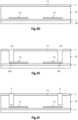
- FIGS. 2B and 2C are schematic and partial views, in cross-section ( fig.2B ) and in top view ( fig.2C ), of a current-assisted photonic demodulator 1 according to an alternative embodiment.
- demodulator 1 is distinguished from those of fig.1A And 2A in particular in that it comprises only one doped collection region, which is then an upper doped region 11 located in the center of the central zone Zc.
- the doped modulation regions are then lower doped regions 12.
- the conductive vias 3 which ensure the electrical polarization of the lower doped regions 12 are not vias distinct from the peripheral lateral portion 2, but are parts (distinct from each other) of the peripheral lateral portion 2. This is here formed from a plurality of distinct parts in the XY plane (without continuity of material between them).
- the peripheral lateral portion 2 is made of a doped conductive material of the same type of conductivity as the lower doped regions 12, here of the p type. In this example, it is made of p+ doped polycrystalline silicon with a boron concentration of approximately 10 20 cm -3 . The electrodes are then in contact with the parts of the peripheral lateral portion 2.
- a p-type doped lateral region 15 may be present in the detection portion 10, along the peripheral lateral portion 2, when the latter is p-type doped as here.
- This p+ doped lateral region 15 makes it possible to prevent the space charge region of the demodulator 1 from extending to the lateral edge of the detection portion 10. Thus, the contribution of this region (potentially not free from defects linked to the production of the trenches) to the dark current is limited.
- FIGS. 3A to 3L illustrate different steps of a manufacturing process of a matrix of current-assisted photonic demodulators 1 similar to that illustrated in the fig.1A .
- the demodulators 1 here have a planar configuration. They are made from germanium, and are therefore suitable for detecting infrared radiation in the near infrared.
- the detection portions 10 are made from germanium. In this example, they are made from a growth SOI substrate.
- a growth SOI substrate is provided, the upper layer 5 of which is a layer of monocrystalline silicon 10 to 100nm thick.
- the growth temperature can be 400°C.
- the lower doped regions 12 are then produced by lithography and localized etching of the p++ doped layer 22, with etching stopped on the layer lower 21 in nested germanium.
- Each lower 12 doped region extends between a proximal 12p end and a distant 12e end in the XY plane.
- the proximal 12p ends delimit the optical window along the X axis.
- the dimension along the X axis of the optical window depends on the pixel pitch, and can thus range from 1.5 ⁇ m to several tens of microns.
- the main semiconductor layer 23 is produced by epitaxy from the layer 21 of nested germanium and the lower doped regions 12.
- the main semiconductor layer 23 is made of unintentionally doped germanium and has a thickness of between approximately 700 and 800 nm. It can be produced as described in particular in the publication of Hartmann & Aubin entitled Assessment of the growth/etch back technique for the production of Ge strain-relaxed buffers on Si, Journal of Crystal Growth, 488 (2016), 43
- the main semiconductor layer 23 then has a very low density of emerging dislocations (for example of the order of 10 7 dislocations/cm 2 ), which contributes to reducing the dark current in the detection portion 10 of the demodulator 1.
- CMP chemical-mechanical planarization
- a passivation dielectric layer 4 is deposited on the upper face F1 of the main semiconductor layer 23 (the layer 21 is integrated into the layer 23).
- This passivation dielectric layer 4 can be formed of a first passivation sub-layer made for example of an aluminum oxide deposited by atomic layer deposition (ALD) with a thickness of the order of 10 to 50nm, for example 10nm, or even by a thin layer of unintentionally doped silicon with a thickness ranging from 1 to 4nm, deposited by epitaxy on the germanium of the detection portion 10.
- ALD atomic layer deposition
- a second sub-layer made for example of a silicon oxide such as SiO 2 TEOS (tetraethyl orthosilicate) with a thickness of the order of 100 to 500nm, is deposited on the first underlying sub-layer.
- SiO 2 TEOS tetraethyl orthosilicate
- notches 24 are then made in the main layer 23, extending along the Z axis from the upper face F1 until they open onto the lower doped regions 12, at the distal ends 12d. These notches 24 are made by lithography and localized etching, with etching stopped on the p++ doped germanium of the regions lower doped 12. The transverse dimensions of these notches 24 can be of the order of 0.5 to 1 ⁇ m approximately.
- the conductive vias 3 are then produced by depositing an electrically conductive material in the notches 24.
- the notches 24 are filled by epitaxy at a temperature of approximately 600°C with boron-doped p-type germanium with a concentration of approximately 10 19 cm -3 .
- a CMP planarization step is then carried out to eliminate the p+ doped germanium resting on the passivation dielectric layer 4.
- a peripheral trench 25 is then made in the main layer 23, making it possible to pixelate the demodulators 1 by the peripheral lateral portions 2.
- a localized etching of the main layer 23 is thus carried out to open here onto the BOX oxide layer 20.
- Each trench 25 here extends continuously in the XY plane around a detection portion 10.
- a plurality of detection portions 10 are thus obtained, separated from each other by a continuous trench 25. They are preferably obtained by an anisotropic etching technique, so as to obtain a substantially vertical lateral border along the Z axis.
- the trenches 25 have a transverse dimension (width) in the XY plane which can be between 0.5 ⁇ m and 2 ⁇ m, for example equal to 1 ⁇ m.
- the detection portions 10 can thus have a shape in the XY plane, for example circular, oval, polygonal, for example square, or any other shape.
- the peripheral lateral portion 2 is produced by epitaxy in the trenches 25 of a crystalline semiconductor material here based on silicon, at a temperature between 500°C and 700°C.
- a crystalline semiconductor material here based on silicon, at a temperature between 500°C and 700°C.
- This is polycrystalline silicon. It can be p-type doped, for example with boron with a doping level of the order of 4 ⁇ 10 19 cm -3 .
- This material has a thermal expansion coefficient lower than that of the germanium of the detection portion 10, so that upon returning to room temperature (after epitaxy of the polysilicon in the peripheral trench 25), the detection portion 10 has mechanical stresses in horizontal tension and vertical compression.
- an interdiffusion annealing is carried out to form the SiGe-based lateral zone 14.
- a chemical mechanical polishing (CMP) step is then carried out, with a stop on the upper face of the passivation dielectric layer 4, to remove the excess silicon-based material and planarize the upper face of the stack.
- CMP chemical mechanical polishing
- non-through notches 26 are made in the dielectric passivation layer 4, leaving an unetched part of, for example, 20nm.
- a resin 27 implantation mask
- the upper doped regions 11, here n+ doped are produced by ion implantation of phosphorus (or even with arsenic or antimony) in the detection portion 10.
- the doping level can be of the order of 5 ⁇ 10 18 to 10 20 cm -3 .
- the upper doped regions 11 are therefore flush with the upper face F1 and are located above the lower doped regions 12. Here, they are located perpendicular to the proximal ends 12p of the lower doped regions 12.
- the resin 27 is then removed, and an activation annealing of the phosphorus is carried out.
- the upper doped regions 11 can also be produced by resumption of germanium epitaxy in notches made in the detection portion 10 from the face F1, with n-type doping during growth.
- ion implantation is preferred so as to preserve the mechanical constraints present in the detection portion 10.
- a new dielectric layer is deposited on the underlying dielectric layer 4, so as to cover the detection portion 10, the conductive vias 3 and the peripheral lateral portion 2.
- the modulation electrodes M1 and M2 are produced, which extend through the dielectric passivation layer 4 and come into contact with the conductive vias 3, as well as the collection electrodes C1 and C2, which extend through the dielectric passivation layer 4 and come into contact with the upper doped regions 11.
Landscapes
- Physics & Mathematics (AREA)
- General Physics & Mathematics (AREA)
- Engineering & Computer Science (AREA)
- Microelectronics & Electronic Packaging (AREA)
- Optics & Photonics (AREA)
- Spectroscopy & Molecular Physics (AREA)
- Light Receiving Elements (AREA)
- Photometry And Measurement Of Optical Pulse Characteristics (AREA)
- Optical Communication System (AREA)
Claims (15)
- Stromunterstützter Photonendemodulator (1), geeignet zur Erfassung einer relevanten Lichtstrahlung, umfassend:∘ einen Erfassungsabschnitt (10), der eine erste Seite (F1) und eine zweite Seite (F2) aufweist, die sich gegenüberstehen und parallel zu einer Hauptebene sind, und eine zentrale Zone (Zc) zur Erfassung der einfallenden Lichtstrahlung umfasst,• hergestellt aus einem ersten kristallinen halbleitenden Material auf Basis von Germanium,• umfassend dotierte Bereiche, darunter:- mindestens zwei modulationsdotierte, p-dotierte Bereiche, die dazu bestimmt sind, einen Driftstrom im Erfassungsabschnitt (10) zu erzeugen und zu modulieren;- mindestens einen n-dotierten Sammelbereich, der dazu bestimmt ist, die bei der Absorption der relevanten Lichtstrahlung photogen erzeugten Minoritätsladungsträger zu sammeln;∘ eine dielektrische Passivierungsschicht (4), die auf der Basis eines elektrisch isolierenden Materials hergestellt ist und die erste Seite (F1) bedeckt;∘ Elektroden (M1, M2, C1, C2), die sich auf der ersten Seite (F1) befinden und die dielektrische Passivierungsschicht (4) durchqueren, darunter Modulationselektroden (M1, M2), die in elektrischem Kontakt mit den modulationsdotierten Bereichen stehen; und mindestens eine Sammelelektrode (C1, C2), die in elektrischem Kontakt mit mindestens dem dotierten Sammelbereich steht;∘ dadurch gekennzeichnet, dass er einen peripheren seitlichen Abschnitt (2) umfasst, der den Erfassungsabschnitt (10) in der Hauptebene umgibt,• die auf der Basis eines zweiten Materials mit einem geringeren thermischen Ausdehnungskoeffizienten als das erste Material hergestellt wird, wobei der Erfassungsabschnitt (10) dann mechanische Spannungen in der Hauptebene und mechanische Druckspannungen entlang einer vertikalen Achse orthogonal zur Hauptebene aufweist;∘ und, dass die dotierten Bereiche in einer vertikalen Anordnung wie folgt angeordnet sind:• mindestens ein nach einem ersten Leitfähigkeitstyp dotierter Bereich, der als oberer dotierter Bereich (11) bezeichnet wird, bündig mit der ersten Seite (F1) ist und sich in der Nähe der zentralen Zone (Zc) befindet;• mindestens zwei nach einem zweiten Leitfähigkeitstyp gegenüber dem ersten Typ dotierte Bereiche, untere dotierte Bereiche (12), befinden sich in einem Abstand entlang der vertikalen Achse des oberen dotierten Bereichs (11).
- Photonendemodulator (1) nach Anspruch 1, wobei sich jeder untere dotierte Bereich (12) parallel zur Hauptebene in Richtung des zentralen Bereichs (Zc) und des oberen dotierten Bereichs (11) erstreckt und ein distales Ende (12d) entfernt vom zentralen Bereich (Zc) und ein proximales Ende (12p) in Richtung des zentralen Bereichs (Zc) aufweist.
- Photonendemodulator (1) nach Anspruch 1 oder 2, umfassend leitende Vias (3), die sich entlang der vertikalen Achse der ersten Seite (F1) erstrecken und in elektrischem Kontakt mit den unteren dotierten Bereichen (12) stehen.
- Photonendemodulator (1) nach Anspruch 3, wobei die leitenden Vias (3) vom peripheren seitlichen Abschnitt (2) getrennt sind; oder die leitenden Vias (3) voneinander getrennte Teile des peripheren seitlichen Abschnitts (2) sind, wobei dieser dann aus einem elektrisch leitenden Material hergestellt ist.
- Photonendemodulator (1) nach einem der Ansprüche 3 bis 4, wobei die Elektrode(n) in Kontakt mit dem/den oberen dotierten Bereich(en) (11) näher an der zentralen Zone (Zc) sind als die Elektroden in Kontakt mit den leitenden Vias (3).
- Photonendemodulator (1) nach einem der Ansprüche 1 bis 5, umfassend zwei untere dotierte Modulationsbereiche (12), und umfassend einen einzigen oberen dotierten Sammlerbereich (11), der sich in der zentralen Zone (Zc) und in der Hauptebene entfernt von den unteren dotierten Modulationsbereichen (12) befindet.
- Photonendemodulator (1) nach einem der Ansprüche 1 bis 5, umfassend zwei obere dotierte Bereiche (11), die jeweils senkrecht zu einem der unteren dotierten Bereiche (12) liegen.
- Photonendemodulator (1) nach einem der Ansprüche 1 bis 7, wobei für einen vertikal benachbarten oberen dotierten Bereich (11) und einen vertikal benachbarten unteren dotierten Bereich (12) ein vertikaler Abstand, entlang der vertikalen Achse zwischen den dotierten Bereichen (11, 12) kleiner als ein horizontaler Abstand in der Hauptebene ist, zwischen der Elektrode, die mit dem oberen dotierten Bereich (11) verbunden ist, und der Elektrode, die mit dem Leiter (3) des benachbarten unteren dotierten Bereichs (12) verbunden ist.
- Photonendemodulator (1) nach einem der Ansprüche 1 bis 8, wobei der/die obere(n) dotierte(n) Bereich(e) (11) Sammelbereiche und die untere(n) dotierte(n) Bereich(e) (12) Modulationsbereiche sind.
- Photonendemodulator (1) nach einem der Ansprüche 1 bis 9, wobei der periphere seitliche Abschnitt (2) auf Siliziumbasis ausgeführt ist und wobei der Erfassungsabschnitt (10) eine seitliche Zone (14) auf SiGe-Basis umfasst, der sich an der Schnittstelle zum peripheren seitlichen Abschnitt (2) befindet.
- Photonendemodulator (1) nach einem der Ansprüche 1 bis 10, wobei die unteren dotierten Bereiche (12) näher an der zweiten Seite (F2) als an der ersten Seite (F1) liegen.
- Fertigungsverfahren eines Photonendemodulators (1) nach einem der vorhergehenden Ansprüche, das folgende Schritte umfasst:∘ Herstellung, durch Epitaxie aus einer Trägerschicht (5), einer ersten Schicht (22) auf Basis von dotiertem Germanium;∘ Herstellung der unteren dotierten Bereiche (12) durch lokalisierte Ätzen der ersten Schicht (22) auf Basis von dotiertem Germanium;∘ Herstellung durch Epitaxie einer Hauptschicht (23) auf Basis von nicht absichtlich dotiertem Germanium auf und in Kontakt mit den unteren dotierten Bereichen (12);∘ Herstellung eines Grabens (25) durch die Hauptschicht (23), die den Erfassungsabschnitt (10) umgibt;∘ Herstellung des peripheren seitlichen Abschnitts (2) im Graben (25) bei einer Temperatur, die über der Umgebungstemperatur liegt, so dass der Erfassungsabschnitt (10) nach Rückkehr zur Umgebungstemperatur in der Hauptebene gespannt und entlang der vertikalen Achse komprimiert ist;∘ Herstellung eines oder mehrerer oberer dotierter Bereiche (11) in dem Erfassungsabschnitt (10);∘ Ablagerung einer dielektrischen Passivierungsschicht (4) auf dem Erfassungsabschnitt (10);∘ Herstellung von Modulationselektroden und Sammelelektroden.
- Fertigungsverfahren nach Anspruch 12, umfassend vor der Herstellung des Grabens (25) einen Schritt zur Herstellung von zwei ersten Aussparungen (24), die auf die unteren dotierten Bereiche (12) münden, gefolgt von einem Schritt zur Herstellung von leitenden Vias (3) in den ersten Aussparungen (24).
- Fertigungsverfahren nach Anspruch 12, so dass dieser bei der Herstellung des Grabens (25) auf die unteren dotierten Bereiche (12) mündet, so dass der periphere seitliche Abschnitt (2) diese dann berührt.
- Fertigungsverfahren nach einem der Ansprüche 12 bis 14, wobei der/die obere(n) dotierte(n) Bereich(e) (11) durch lokalisierte lonenimplantation hergestellt wird/werden.
Applications Claiming Priority (1)
| Application Number | Priority Date | Filing Date | Title |
|---|---|---|---|
| FR2213208A FR3143193B1 (fr) | 2022-12-12 | 2022-12-12 | Démodulateur photonique assisté par courant comportant des régions dopées de modulation et de collection agencées verticalement et situees dans une zone en compression |
Publications (2)
| Publication Number | Publication Date |
|---|---|
| EP4386873A1 EP4386873A1 (de) | 2024-06-19 |
| EP4386873B1 true EP4386873B1 (de) | 2025-06-11 |
Family
ID=85726942
Family Applications (1)
| Application Number | Title | Priority Date | Filing Date |
|---|---|---|---|
| EP23215188.6A Active EP4386873B1 (de) | 2022-12-12 | 2023-12-08 | Stromunterstützter photonischer demodulator mit vertikal angeordneten dotierten modulations- und sammelregionen in einer zone unter druckbeanspruchung |
Country Status (4)
| Country | Link |
|---|---|
| US (1) | US20240192440A1 (de) |
| EP (1) | EP4386873B1 (de) |
| CN (1) | CN118198172A (de) |
| FR (1) | FR3143193B1 (de) |
Families Citing this family (1)
| Publication number | Priority date | Publication date | Assignee | Title |
|---|---|---|---|---|
| FR3142606B1 (fr) * | 2022-11-29 | 2024-11-15 | Commissariat Energie Atomique | Démodulateur photonique assisté par courant à performances améliorées comportant des électrodes intermédiaires |
Family Cites Families (8)
| Publication number | Priority date | Publication date | Assignee | Title |
|---|---|---|---|---|
| JP4814095B2 (ja) * | 2003-09-18 | 2011-11-09 | イーツェー−ハウス ゲーエムベーハー | 3次元距離測定用の光電子センサおよびデバイス |
| US10741598B2 (en) * | 2015-11-06 | 2020-08-11 | Atrilux, Inc. | High-speed light sensing apparatus II |
| DE102016208343B4 (de) * | 2016-05-13 | 2020-02-27 | Infineon Technologies Ag | Optische Sensoreinrichtung und Verfahren zur Herstellung der optischen Sensoreinrichtung |
| US11105928B2 (en) * | 2018-02-23 | 2021-08-31 | Artilux, Inc. | Light-sensing apparatus and light-sensing method thereof |
| FR3080489B1 (fr) * | 2018-04-18 | 2020-05-08 | Commissariat A L'energie Atomique Et Aux Energies Alternatives | Dispositif optoelectronique a diode contrainte en tension par effet piezoelectrique inverse |
| FR3101727B1 (fr) * | 2019-10-08 | 2021-09-17 | Commissariat Energie Atomique | procede de fabrication d’au moins une photodiode planaire contrainte en tension |
| US20240030257A1 (en) * | 2020-12-08 | 2024-01-25 | C/O Sony Semiconductor Solutions Corporation | Imaging device and ranging device |
| FR3142606B1 (fr) * | 2022-11-29 | 2024-11-15 | Commissariat Energie Atomique | Démodulateur photonique assisté par courant à performances améliorées comportant des électrodes intermédiaires |
-
2022
- 2022-12-12 FR FR2213208A patent/FR3143193B1/fr active Active
-
2023
- 2023-12-08 EP EP23215188.6A patent/EP4386873B1/de active Active
- 2023-12-11 US US18/535,194 patent/US20240192440A1/en active Pending
- 2023-12-11 CN CN202311694941.5A patent/CN118198172A/zh active Pending
Also Published As
| Publication number | Publication date |
|---|---|
| EP4386873A1 (de) | 2024-06-19 |
| US20240192440A1 (en) | 2024-06-13 |
| FR3143193B1 (fr) | 2024-11-29 |
| FR3143193A1 (fr) | 2024-06-14 |
| CN118198172A (zh) | 2024-06-14 |
Similar Documents
| Publication | Publication Date | Title |
|---|---|---|
| EP3657556B1 (de) | Herstellungsverfahren mindestens einer passivierten planaren fotodiode mit reduziertem dunkelstrom | |
| EP3660930B1 (de) | Herstellungsverfahren einer fotodiodenmatrix auf germaniumbasis und mit schwachem dunkelstrom | |
| EP3084843B1 (de) | Quantendetektionselement mit geringem rauschen und verfahren zur herstellung solch eines lichtdetektionselements | |
| EP2587539B1 (de) | CMOS-UTBB-Bildaufnehmer | |
| EP3971995B1 (de) | Passivierte fotodiode mit einem ferroelektrischen peripheren teil | |
| EP3806167B1 (de) | Verfahren zur herstellung mindestens einer planaren fotodiode unter spannung | |
| EP3782205A1 (de) | Optoelektronische vorrichtung mit einer durch eine inverse piezoelektrische wirkung unter zugspannung stehenden diode | |
| EP2865017B1 (de) | Halbleiterstruktur mit absorbierendem bereich in einem fokusierenden resonator | |
| EP4386873B1 (de) | Stromunterstützter photonischer demodulator mit vertikal angeordneten dotierten modulations- und sammelregionen in einer zone unter druckbeanspruchung | |
| EP2432033B1 (de) | Bispektraler Mehrschichtdetektor mit Fotodioden | |
| EP4379821B1 (de) | Stromunterstützter photonischer demodulator mit verbesserter leistung und zwischenelektroden | |
| EP4184594B1 (de) | Germanium-photodiode mit reduziertem dunkelstrom mit einem auf sige/ge basierenden peripheren zwischenteil | |
| EP4354524B1 (de) | Planare photodiode auf germaniumbasis mit einer kompressiven peripheren seitlichen zone | |
| EP3703138B1 (de) | Struktur zur erkennung einer elektromagnetischen strahlung mit hoher absorptionseffizienz, und herstellungsverfahren einer solchen struktur | |
| EP4292136B1 (de) | Germanium-photodiode mit optimierten metallkontakten | |
| FR3162870A1 (fr) | Démodulateur photonique assisté par courant à consommation d’énergie réduite | |
| FR2742581A1 (fr) | Detecteur infrarouge bicolore a coherence spatio-temporelle planaire |
Legal Events
| Date | Code | Title | Description |
|---|---|---|---|
| PUAI | Public reference made under article 153(3) epc to a published international application that has entered the european phase |
Free format text: ORIGINAL CODE: 0009012 |
|
| STAA | Information on the status of an ep patent application or granted ep patent |
Free format text: STATUS: REQUEST FOR EXAMINATION WAS MADE |
|
| 17P | Request for examination filed |
Effective date: 20231208 |
|
| AK | Designated contracting states |
Kind code of ref document: A1 Designated state(s): AL AT BE BG CH CY CZ DE DK EE ES FI FR GB GR HR HU IE IS IT LI LT LU LV MC ME MK MT NL NO PL PT RO RS SE SI SK SM TR |
|
| RAP3 | Party data changed (applicant data changed or rights of an application transferred) |
Owner name: COMMISSARIAT A L'ENERGIE ATOMIQUE ET AUX ENERGIESALTERNATIVES |
|
| REG | Reference to a national code |
Ref country code: DE Ref legal event code: R079 Free format text: PREVIOUS MAIN CLASS: H01L0031111000 Ipc: H10F0030260000 Ref document number: 602023003969 Country of ref document: DE |
|
| GRAP | Despatch of communication of intention to grant a patent |
Free format text: ORIGINAL CODE: EPIDOSNIGR1 |
|
| STAA | Information on the status of an ep patent application or granted ep patent |
Free format text: STATUS: GRANT OF PATENT IS INTENDED |
|
| INTG | Intention to grant announced |
Effective date: 20250113 |
|
| RIC1 | Information provided on ipc code assigned before grant |
Ipc: H10F 30/26 20250101AFI20250109BHEP |
|
| GRAS | Grant fee paid |
Free format text: ORIGINAL CODE: EPIDOSNIGR3 |
|
| GRAA | (expected) grant |
Free format text: ORIGINAL CODE: 0009210 |
|
| STAA | Information on the status of an ep patent application or granted ep patent |
Free format text: STATUS: THE PATENT HAS BEEN GRANTED |
|
| AK | Designated contracting states |
Kind code of ref document: B1 Designated state(s): AL AT BE BG CH CY CZ DE DK EE ES FI FR GB GR HR HU IE IS IT LI LT LU LV MC ME MK MT NL NO PL PT RO RS SE SI SK SM TR |
|
| REG | Reference to a national code |
Ref country code: GB Ref legal event code: FG4D Free format text: NOT ENGLISH |
|
| REG | Reference to a national code |
Ref country code: CH Ref legal event code: EP |
|
| REG | Reference to a national code |
Ref country code: DE Ref legal event code: R096 Ref document number: 602023003969 Country of ref document: DE |
|
| REG | Reference to a national code |
Ref country code: IE Ref legal event code: FG4D Free format text: LANGUAGE OF EP DOCUMENT: FRENCH |
|
| PG25 | Lapsed in a contracting state [announced via postgrant information from national office to epo] |
Ref country code: ES Free format text: LAPSE BECAUSE OF FAILURE TO SUBMIT A TRANSLATION OF THE DESCRIPTION OR TO PAY THE FEE WITHIN THE PRESCRIBED TIME-LIMIT Effective date: 20250611 Ref country code: FI Free format text: LAPSE BECAUSE OF FAILURE TO SUBMIT A TRANSLATION OF THE DESCRIPTION OR TO PAY THE FEE WITHIN THE PRESCRIBED TIME-LIMIT Effective date: 20250611 |
|
| REG | Reference to a national code |
Ref country code: LT Ref legal event code: MG9D |
|
| PG25 | Lapsed in a contracting state [announced via postgrant information from national office to epo] |
Ref country code: GR Free format text: LAPSE BECAUSE OF FAILURE TO SUBMIT A TRANSLATION OF THE DESCRIPTION OR TO PAY THE FEE WITHIN THE PRESCRIBED TIME-LIMIT Effective date: 20250912 Ref country code: NO Free format text: LAPSE BECAUSE OF FAILURE TO SUBMIT A TRANSLATION OF THE DESCRIPTION OR TO PAY THE FEE WITHIN THE PRESCRIBED TIME-LIMIT Effective date: 20250911 |
|
| REG | Reference to a national code |
Ref country code: NL Ref legal event code: MP Effective date: 20250611 |
|
| PG25 | Lapsed in a contracting state [announced via postgrant information from national office to epo] |
Ref country code: BG Free format text: LAPSE BECAUSE OF FAILURE TO SUBMIT A TRANSLATION OF THE DESCRIPTION OR TO PAY THE FEE WITHIN THE PRESCRIBED TIME-LIMIT Effective date: 20250611 |
|
| PG25 | Lapsed in a contracting state [announced via postgrant information from national office to epo] |
Ref country code: HR Free format text: LAPSE BECAUSE OF FAILURE TO SUBMIT A TRANSLATION OF THE DESCRIPTION OR TO PAY THE FEE WITHIN THE PRESCRIBED TIME-LIMIT Effective date: 20250611 |
|
| PG25 | Lapsed in a contracting state [announced via postgrant information from national office to epo] |
Ref country code: RS Free format text: LAPSE BECAUSE OF FAILURE TO SUBMIT A TRANSLATION OF THE DESCRIPTION OR TO PAY THE FEE WITHIN THE PRESCRIBED TIME-LIMIT Effective date: 20250911 |
|
| PG25 | Lapsed in a contracting state [announced via postgrant information from national office to epo] |
Ref country code: LV Free format text: LAPSE BECAUSE OF FAILURE TO SUBMIT A TRANSLATION OF THE DESCRIPTION OR TO PAY THE FEE WITHIN THE PRESCRIBED TIME-LIMIT Effective date: 20250611 |
|
| PG25 | Lapsed in a contracting state [announced via postgrant information from national office to epo] |
Ref country code: NL Free format text: LAPSE BECAUSE OF FAILURE TO SUBMIT A TRANSLATION OF THE DESCRIPTION OR TO PAY THE FEE WITHIN THE PRESCRIBED TIME-LIMIT Effective date: 20250611 |
|
| PG25 | Lapsed in a contracting state [announced via postgrant information from national office to epo] |
Ref country code: PT Free format text: LAPSE BECAUSE OF FAILURE TO SUBMIT A TRANSLATION OF THE DESCRIPTION OR TO PAY THE FEE WITHIN THE PRESCRIBED TIME-LIMIT Effective date: 20251013 |
|
| REG | Reference to a national code |
Ref country code: AT Ref legal event code: MK05 Ref document number: 1803299 Country of ref document: AT Kind code of ref document: T Effective date: 20250611 |
|
| PG25 | Lapsed in a contracting state [announced via postgrant information from national office to epo] |
Ref country code: IS Free format text: LAPSE BECAUSE OF FAILURE TO SUBMIT A TRANSLATION OF THE DESCRIPTION OR TO PAY THE FEE WITHIN THE PRESCRIBED TIME-LIMIT Effective date: 20251011 |
|
| PG25 | Lapsed in a contracting state [announced via postgrant information from national office to epo] |
Ref country code: SM Free format text: LAPSE BECAUSE OF FAILURE TO SUBMIT A TRANSLATION OF THE DESCRIPTION OR TO PAY THE FEE WITHIN THE PRESCRIBED TIME-LIMIT Effective date: 20250611 Ref country code: AT Free format text: LAPSE BECAUSE OF FAILURE TO SUBMIT A TRANSLATION OF THE DESCRIPTION OR TO PAY THE FEE WITHIN THE PRESCRIBED TIME-LIMIT Effective date: 20250611 |
|
| PGFP | Annual fee paid to national office [announced via postgrant information from national office to epo] |
Ref country code: FR Payment date: 20251222 Year of fee payment: 3 |
|
| PG25 | Lapsed in a contracting state [announced via postgrant information from national office to epo] |
Ref country code: CZ Free format text: LAPSE BECAUSE OF FAILURE TO SUBMIT A TRANSLATION OF THE DESCRIPTION OR TO PAY THE FEE WITHIN THE PRESCRIBED TIME-LIMIT Effective date: 20250611 |
|
| PG25 | Lapsed in a contracting state [announced via postgrant information from national office to epo] |
Ref country code: PL Free format text: LAPSE BECAUSE OF FAILURE TO SUBMIT A TRANSLATION OF THE DESCRIPTION OR TO PAY THE FEE WITHIN THE PRESCRIBED TIME-LIMIT Effective date: 20250611 |
|
| PG25 | Lapsed in a contracting state [announced via postgrant information from national office to epo] |
Ref country code: EE Free format text: LAPSE BECAUSE OF FAILURE TO SUBMIT A TRANSLATION OF THE DESCRIPTION OR TO PAY THE FEE WITHIN THE PRESCRIBED TIME-LIMIT Effective date: 20250611 |
|
| PG25 | Lapsed in a contracting state [announced via postgrant information from national office to epo] |
Ref country code: SK Free format text: LAPSE BECAUSE OF FAILURE TO SUBMIT A TRANSLATION OF THE DESCRIPTION OR TO PAY THE FEE WITHIN THE PRESCRIBED TIME-LIMIT Effective date: 20250611 |