EP4386147A1 - Construction machine - Google Patents
Construction machine Download PDFInfo
- Publication number
- EP4386147A1 EP4386147A1 EP23752812.0A EP23752812A EP4386147A1 EP 4386147 A1 EP4386147 A1 EP 4386147A1 EP 23752812 A EP23752812 A EP 23752812A EP 4386147 A1 EP4386147 A1 EP 4386147A1
- Authority
- EP
- European Patent Office
- Prior art keywords
- lever
- control lever
- disposed
- gate lock
- guide groove
- Prior art date
- Legal status (The legal status is an assumption and is not a legal conclusion. Google has not performed a legal analysis and makes no representation as to the accuracy of the status listed.)
- Granted
Links
Images




Classifications
-
- E—FIXED CONSTRUCTIONS
- E02—HYDRAULIC ENGINEERING; FOUNDATIONS; SOIL SHIFTING
- E02F—DREDGING; SOIL-SHIFTING
- E02F9/00—Component parts of dredgers or soil-shifting machines, not restricted to one of the kinds covered by groups E02F3/00 - E02F7/00
- E02F9/16—Cabins, platforms, or the like, for drivers
- E02F9/166—Cabins, platforms, or the like, for drivers movable, tiltable or pivoting, e.g. movable seats, dampening arrangements of cabins
-
- E—FIXED CONSTRUCTIONS
- E02—HYDRAULIC ENGINEERING; FOUNDATIONS; SOIL SHIFTING
- E02F—DREDGING; SOIL-SHIFTING
- E02F9/00—Component parts of dredgers or soil-shifting machines, not restricted to one of the kinds covered by groups E02F3/00 - E02F7/00
- E02F9/24—Safety devices, e.g. for preventing overload
-
- B—PERFORMING OPERATIONS; TRANSPORTING
- B60—VEHICLES IN GENERAL
- B60N—SEATS SPECIALLY ADAPTED FOR VEHICLES; VEHICLE PASSENGER ACCOMMODATION NOT OTHERWISE PROVIDED FOR
- B60N2/00—Seats specially adapted for vehicles; Arrangement or mounting of seats in vehicles
- B60N2/75—Arm-rests
- B60N2/79—Adaptations for additional use of the arm-rests
- B60N2/797—Adaptations for additional use of the arm-rests for use as electrical control means, e.g. switches
-
- E—FIXED CONSTRUCTIONS
- E02—HYDRAULIC ENGINEERING; FOUNDATIONS; SOIL SHIFTING
- E02F—DREDGING; SOIL-SHIFTING
- E02F3/00—Dredgers; Soil-shifting machines
- E02F3/04—Dredgers; Soil-shifting machines mechanically-driven
- E02F3/28—Dredgers; Soil-shifting machines mechanically-driven with digging tools mounted on a dipper- or bucket-arm, i.e. there is either one arm or a pair of arms, e.g. dippers, buckets
- E02F3/30—Dredgers; Soil-shifting machines mechanically-driven with digging tools mounted on a dipper- or bucket-arm, i.e. there is either one arm or a pair of arms, e.g. dippers, buckets with a dipper-arm pivoted on a cantilever beam, i.e. boom
- E02F3/32—Dredgers; Soil-shifting machines mechanically-driven with digging tools mounted on a dipper- or bucket-arm, i.e. there is either one arm or a pair of arms, e.g. dippers, buckets with a dipper-arm pivoted on a cantilever beam, i.e. boom working downwardly and towards the machine, e.g. with backhoes
-
- E—FIXED CONSTRUCTIONS
- E02—HYDRAULIC ENGINEERING; FOUNDATIONS; SOIL SHIFTING
- E02F—DREDGING; SOIL-SHIFTING
- E02F9/00—Component parts of dredgers or soil-shifting machines, not restricted to one of the kinds covered by groups E02F3/00 - E02F7/00
- E02F9/16—Cabins, platforms, or the like, for drivers
-
- E—FIXED CONSTRUCTIONS
- E02—HYDRAULIC ENGINEERING; FOUNDATIONS; SOIL SHIFTING
- E02F—DREDGING; SOIL-SHIFTING
- E02F9/00—Component parts of dredgers or soil-shifting machines, not restricted to one of the kinds covered by groups E02F3/00 - E02F7/00
- E02F9/20—Drives; Control devices
- E02F9/2004—Control mechanisms, e.g. control levers
-
- E—FIXED CONSTRUCTIONS
- E02—HYDRAULIC ENGINEERING; FOUNDATIONS; SOIL SHIFTING
- E02F—DREDGING; SOIL-SHIFTING
- E02F9/00—Component parts of dredgers or soil-shifting machines, not restricted to one of the kinds covered by groups E02F3/00 - E02F7/00
- E02F9/20—Drives; Control devices
- E02F9/2004—Control mechanisms, e.g. control levers
- E02F9/2012—Setting the functions of the control levers, e.g. changing assigned functions among operations levers, setting functions dependent on the operator or seat orientation
-
- E—FIXED CONSTRUCTIONS
- E02—HYDRAULIC ENGINEERING; FOUNDATIONS; SOIL SHIFTING
- E02F—DREDGING; SOIL-SHIFTING
- E02F9/00—Component parts of dredgers or soil-shifting machines, not restricted to one of the kinds covered by groups E02F3/00 - E02F7/00
- E02F9/20—Drives; Control devices
- E02F9/22—Hydraulic or pneumatic drives
- E02F9/2246—Control of prime movers, e.g. depending on the hydraulic load of work tools
-
- E—FIXED CONSTRUCTIONS
- E02—HYDRAULIC ENGINEERING; FOUNDATIONS; SOIL SHIFTING
- E02F—DREDGING; SOIL-SHIFTING
- E02F9/00—Component parts of dredgers or soil-shifting machines, not restricted to one of the kinds covered by groups E02F3/00 - E02F7/00
- E02F9/26—Indicating devices
- E02F9/264—Sensors and their calibration for indicating the position of the work tool
-
- G—PHYSICS
- G05—CONTROLLING; REGULATING
- G05G—CONTROL DEVICES OR SYSTEMS INSOFAR AS CHARACTERISED BY MECHANICAL FEATURES ONLY
- G05G5/00—Means for preventing, limiting or returning the movements of parts of a control mechanism, e.g. locking controlling member
- G05G5/005—Means for preventing, limiting or returning the movements of parts of a control mechanism, e.g. locking controlling member for preventing unintentional use of a control mechanism
-
- B—PERFORMING OPERATIONS; TRANSPORTING
- B60—VEHICLES IN GENERAL
- B60Y—INDEXING SCHEME RELATING TO ASPECTS CROSS-CUTTING VEHICLE TECHNOLOGY
- B60Y2200/00—Type of vehicle
- B60Y2200/40—Special vehicles
- B60Y2200/41—Construction vehicles, e.g. graders, excavators
- B60Y2200/412—Excavators
-
- G—PHYSICS
- G05—CONTROLLING; REGULATING
- G05G—CONTROL DEVICES OR SYSTEMS INSOFAR AS CHARACTERISED BY MECHANICAL FEATURES ONLY
- G05G9/00—Manually-actuated control mechanisms provided with one single controlling member co-operating with two or more controlled members, e.g. selectively, simultaneously
- G05G9/02—Manually-actuated control mechanisms provided with one single controlling member co-operating with two or more controlled members, e.g. selectively, simultaneously the controlling member being movable in different independent ways, movement in each individual way actuating one controlled member only
- G05G9/04—Manually-actuated control mechanisms provided with one single controlling member co-operating with two or more controlled members, e.g. selectively, simultaneously the controlling member being movable in different independent ways, movement in each individual way actuating one controlled member only in which movement in two or more ways can occur simultaneously
- G05G9/047—Manually-actuated control mechanisms provided with one single controlling member co-operating with two or more controlled members, e.g. selectively, simultaneously the controlling member being movable in different independent ways, movement in each individual way actuating one controlled member only in which movement in two or more ways can occur simultaneously the controlling member being movable by hand about orthogonal axes, e.g. joysticks
- G05G2009/04703—Mounting of controlling member
- G05G2009/04714—Mounting of controlling member with orthogonal axes
- G05G2009/04718—Mounting of controlling member with orthogonal axes with cardan or gimbal type joint
-
- G—PHYSICS
- G05—CONTROLLING; REGULATING
- G05G—CONTROL DEVICES OR SYSTEMS INSOFAR AS CHARACTERISED BY MECHANICAL FEATURES ONLY
- G05G9/00—Manually-actuated control mechanisms provided with one single controlling member co-operating with two or more controlled members, e.g. selectively, simultaneously
- G05G9/02—Manually-actuated control mechanisms provided with one single controlling member co-operating with two or more controlled members, e.g. selectively, simultaneously the controlling member being movable in different independent ways, movement in each individual way actuating one controlled member only
- G05G9/04—Manually-actuated control mechanisms provided with one single controlling member co-operating with two or more controlled members, e.g. selectively, simultaneously the controlling member being movable in different independent ways, movement in each individual way actuating one controlled member only in which movement in two or more ways can occur simultaneously
- G05G9/047—Manually-actuated control mechanisms provided with one single controlling member co-operating with two or more controlled members, e.g. selectively, simultaneously the controlling member being movable in different independent ways, movement in each individual way actuating one controlled member only in which movement in two or more ways can occur simultaneously the controlling member being movable by hand about orthogonal axes, e.g. joysticks
Definitions
- the present invention relates to construction machines such as a hydraulic excavator provided with console devices on both left and right sides of an operator's seat.
- a hydraulic excavator representative of a construction machine is provided with an automotive vehicle body composed of a lower traveling structure and an upper revolving structure, and a working mechanism disposed on the front side of the upper revolving structure.
- a cab for defining an operator's room therein is disposed on the front left side of the upper revolving structure.
- An operator's seat is disposed within the cab, and console devices each provided with a control lever are arranged on both sides of the operator's seat in the left-right direction.
- An operator sits on the operator's seat from an entrance formed on a left side surface of the cab through an entrance passage on a floor plate and operates the left and right control levers.
- Actuators for a revolving operation of the upper revolving structure and an operation of the working mechanism are controlled in response to operations to the control levers.
- a gate lock lever is disposed in the left console device on the entrance passage side out of the left and right console devices.
- This gate lock lever is operable to control supply of a pilot pressure to the control lever and is displaced to a locking position for prohibiting the operation of the actuator regardless of the operation of the control lever and a lock releasing position for allowing the operation of the actuator in response to the operation of the control lever.
- the gate lock lever is displaced to the locking position, the entrance passage is released, and when the gate lock lever is displaced to the lock releasing position, the entrance passage is blocked out. Because of this configuration, when an operator or the like goes through the released entrance, even if he or she comes in contact with the control lever in error, the actuator can be prevented from inadvertently being operated.
- Patent Document 1 however, the mechanism for moving the console device is not disposed and the entrance passage is narrowed by the console device. Therefore, it is difficult for an operator to go through the entrance passage smoothly.
- Patent Document 2 since the mechanism for adjusting the height position of the control lever relative to the operator's seat is not disposed, it becomes difficult for the operators of various physiques to operate the control lever in a comfortable posture.
- a mechanism that can move in a direction of widening the entrance and a mechanism (height adjusting mechanism) that adjusts the height position of the control lever relative to the operator's seat into the console device on the entrance passage side.
- the gate lock lever since the gate lock lever is disposed in the console device on the entrance passage side, the gate lock lever is changed in a position in association with the movement of the console device of which a position is changed by the height adjusting mechanism.
- the height position of the control lever is adjusted by the height adjusting mechanism, in a case where the height position of the gate lock lever is changed, there is a problem that an operator feels uncomfortable when the operator grips a gripping part of the gate lock lever.
- the gate lock lever is designed to prohibit the operation of the actuator, it is preferable that the gate lock lever is always in the same position, but when the position is changed by the height adjusting mechanism, there occurs a problem that operability to the gate lock lever deteriorates.
- An object of the present invention is to provide a construction machine that can maintain the operability to a gate lock lever to be good even in a case where a height position of a control lever is adjusted relative to an operator's seat.
- a construction machine comprises: an operator's seat; a console device provided with an control lever for operating an actuator; and a gate lock lever that is disposed in the console device and is displaced to a locking position for prohibiting an operation of the actuator in response to an operation of the control lever and a lock releasing position for allowing the operation of the actuator in response to the operation of the control lever, characterized in that the console device includes: a support shaft disposed in a seat base to which the operator's seat is attached; a rotational frame that is supported to be rotatable in an upper-lower direction on the support shaft and to which the control lever is attached; and a height adjusting mechanism for adjusting a position of the rotational frame in a rotating direction centering on the support shaft, and the gate lock lever includes: a base plate that is supported to be rotatable on a first shaft body disposed in the rotational frame and in which a second shaft body is disposed in a position different from that of the first shaft body, and a lever member that is disposed
- the movement of the second shaft body disposed on the base plate of the gate lock lever is restricted by the guide groove of the guide member.
- a hydraulic excavator 1 representative of a construction machine is provided with an automotive lower traveling structure 2 of a crawl type in the front-back direction and an upper revolving structure 3 that is mounted on the lower traveling structure 2 to be capable of revolving thereon.
- the lower traveling structure 2 and the upper revolving structure 3 configure a vehicle body in the hydraulic excavator 1.
- a working mechanism 4 is disposed on the front side of the upper revolving structure 3 to be capable of tilting and lifting thereto.
- the hydraulic excavator 1 travels in the working site by the lower traveling structure 2, and tilts and lifts the working mechanism 4 while revolving the upper revolving structure 3, thus performing an excavating work of earth and sand, or the like.
- the upper revolving structure 3 is provided with a revolving frame 5 as a base.
- a counterweight 6 is disposed on the rear side of the revolving frame 5 to act as a weight balance to the working mechanism 4.
- Mounted equipment devices (none of them are shown) of an engine, a hydraulic pump, a heat exchanger and the like are mounted on the revolving frame 5 to be positioned in the front side to the counterweight 6.
- the mounted equipment devices are covered with an exterior cover 7 disposed on the revolving frame 5.
- a cab 8 is disposed on the front left side of the upper revolving structure 3 to define an operator's room therein.
- the cab 8 rises upward from the revolving frame 5 to be formed in a boxy shape and the operator's room is defined in the inside of the cab 8.
- An entrance 8A for an operator to get in/off the cab 8 and a door 8B for opening/closing the entrance 8A are arranged on the left side surface of the cab 8.
- a lower side of the cab 8 is covered with a floor member 9.
- the floor member 9 configures a floor plate of the cab 8 and as shown in Fig. 2 , is formed as a rectangular plate body elongated in the front-back direction.
- An operator's seat 12, a left console device 13, a right console device 14 and a gate lock lever 25, which will be described later, and the like are arranged in the operator's room in the cab 8, and a left front part of the floor member 9 serves as an entrance passage 9A for the operator to move (getting in/off) between the entrance 8A of the cab 8 and the operator's seat 12.
- An operator's seat support platform 10 is disposed in an intermediate position of the floor member 9 in the front-back direction.
- the operator's seat support platform 10 includes a seating 10A fixed on the floor member 9, a position adjusting mechanism 10B disposed on the seating 10A and a seat base 11 disposed on the position adjusting mechanism 10B. Since operators of various physiques sit on the operator's seat 12, an optimal position of the control lever differs depending on the operator. Therefore, disposing the position adjusting mechanism 10B on the operator's seat support platform 10 enables the operator's seat 12, the left console device 13 and the right console device 14 to be adjusted in a position in the front-back direction and in the upper-lower direction.
- the seat base 11 is located above the position adjusting mechanism 10B and configures a base for attaching the operator's seat 12, the left console device 13, the right console device 14 and the like.
- the seat base 11 is formed in a flat boxy shape as a whole and as shown in Fig. 4 , a left rear projection plate 11A that projects upward is disposed on a left rear part of the seat base 11 and a support shaft 15 to be described later is disposed on the left rear projection plate 11A.
- a right rear projection plate (not shown) is disposed on a right rear part of the seat base 11 in a position symmetrical to the left rear projection plate 11A in the left-right direction and a support shaft (not shown) is disposed on the right rear projection plate.
- a left front projection plate 11B that projects downward is disposed on a left front part of the seat base 11. Further, a left intermediate projection plate 11C that projects downward is disposed, which is in a portion closer to the left rear projection plate 11A, in an intermediate part of the seat base 11 in the front-back direction.
- a guide plate shaft 11D, a stopper shaft 11E and a lower engagement pin 11F are arranged on a lower end side of the left front projection plate 11B at intervals in the front-back direction and respectively project to the left side from the left front projection plate 11B.
- a guide plate 26 to be described later is attached to a projection end side of the guide plate shaft 11D to be rotatable in the front-back direction.
- the stopper shaft 11E holds the guide plate 26 to a lever height adjusting posture as shown in Fig. 3 due to the guide plate 26 abutting on the stopper shaft 11E.
- One end of a coil spring 31 to be described later is engaged to the lower engagement pin 11F.
- a lower gas spring pin 11G is fixed on a lower end side of the left intermediate projection plate 11C and projects to the left side from the left intermediate projection plate 11C.
- a bottom side of a gas spring 30 to be described later is attached to the lower gas spring pin 11G.
- the operator's seat 12 is disposed on the seat base 11 of the operator's seat support platform 10.
- the left console device 13 provided with the control lever 19 is located on the left side of the operator's seat 12 and the right console device 14 provided with the control lever 20 is located on the right side of the operator's seat 12.
- An operator sitting on the operator's seat 12 operates the left and right control levers 19, 20, thereby controlling the operations of actuators of the revolving motor for driving the upper revolving structure 3, the hydraulic cylinder for driving the working mechanism 4, and the like.
- the left console device 13 and the right console device 14 are formed to be substantially symmetrical to each other in the left-right direction. Therefore, hereinafter an explanation will be made of the details of the configuration of the left console device 13 as one of the console devices positioned on the entrance passage 9A-side, and in the right console device 14, components corresponding to those in the left console device 13 are referred to as the identical numerals and an explanation thereof is omitted.
- the left console device 13 is located on the left side of the operator's seat 12 and is provided with the control lever 19 for operating the actuator.
- the left console device 13 configures one of the console devices positioned on the entrance passage 9A-side of the floor member 9.
- the left console device 13 includes the support shaft 15, a rotational bracket 16, a rotational frame 17, the gate lock lever 25, the guide plate 26 and the like.
- the support shaft 15 is disposed on a left rear part of the seat base 11 and projects to the left side.
- the support shaft 15 is formed in a columnar shape and supports the rotational bracket 16 and the rotational frame 17 to be rotatable relative to the seat base 11.
- the rotational bracket 16 is disposed adjacent to the left side of the seat base 11. As shown in Fig. 4 , the rotational bracket 16 is formed in a plate shape extending in the front-back direction as a whole. A shaft through hole 16A is formed in a rear upper side of the rotational bracket 16 and the support shaft 15 is inserted via a bearing in the shaft through hole 16A. With this configuration, the rotational bracket 16 is designed to be rotatable in the upper-lower direction centering on the support shaft 15. A plurality (for example, three holes) of height adjusting holes 16B, 16C, 16D are arranged on the front end side of the rotational bracket 16.
- the height adjusting holes 16B, 16C, 16D are arranged at a constant interval on a circular arc of a radius R1 centering on a center (shaft center of the support shaft 15) of the shaft through hole 16A, and a positioning pin 23 to be described later is fitted selectively into any one of the height adjusting holes 16B, 16C, 16D.
- An upper gas spring pin 16E is disposed in an intermediate part of the rotational bracket 16 in the longitudinal direction (front-back direction).
- the upper gas spring pin 16E is formed in a stepped columnar shape and projects to the left side from the rotational bracket 16.
- a rod side of the gas spring 30 is attached to be rotatable on a projection end of the upper gas spring pin 16E.
- a shaft attachment plate 16G is attached via a spacer 16F on the front side of the rotational bracket 16.
- a third shaft body 16H in a stepped columnar shape is disposed on the shaft attachment plate 16G to project to the left side and a projection end of the third shaft body 16H is engaged to a second guide groove 28 of the guide plate 26.
- the rotational frame 17 is disposed adjacent to the left side of the rotational bracket 16.
- the rotational frame 17 is formed in a frame shape extending in the front-back direction as a whole.
- a shaft through hole 17A is formed in a rear side of the rotational frame 17 and the support shaft 15 is inserted via a bearing in the shaft through hole 17A.
- the rotational frame 17 is designed to be rotatable in the upper-lower direction centering on the support shaft 15.
- a rear-side attachment part 17B in a square cylinder shape is disposed on the upper side of the shaft through hole 17A in the rotational frame 17.
- An armrest 18 on which an operator sitting on the operator's seat 12 places an operator's arm is attached to the rear-side attachment part 17B.
- a boxy front-side attachment part 17C is disposed on the front side of the rotational frame 17.
- the control lever 19 is attached to the front-side attachment part 17C and a pin support case 22 configuring part of a height adjusting mechanism 21 is disposed on the front end of the front-side attachment part 17C.
- a first shaft body 17D in a columnar shape is disposed to project to the left side on the front-side attachment part 17C and a base plate 25A of the gate lock lever 25 is rotatably supported on the first shaft body 17D.
- the control lever 19 is disposed in the left console device 13 and the control lever 20 is disposed in the right console device 14.
- the left and right control levers 19, 20 are operated by an operator to control the operations of actuators such as the revolving motor for performing a revolving operation of the upper revolving structure 3, the hydraulic cylinder configuring part of the working mechanism 4 and the like.
- the control lever 19 includes a pilot valve of a pressure reducing valve type (not shown) attached to the front-side attachment part 17C of the rotational frame 17, and a lever part 19A that extends upward from the pilot valve and is gripped by an operator.
- the control lever 20 on the right side also includes a pilot valve of a pressure reducing valve type (not shown), and a lever part 20A that is gripped by an operator.
- the height adjusting mechanism 21 is disposed on the front side of the left console device 13 to adjust a height position of the control lever 19 relative to the operator's seat 12 in a stepwise fashion (for example, in three stages). It should be noted that a height adjusting mechanism is disposed also on the front side of the right console device 14 to adjust a height position of the control lever 20 and the height adjusting mechanism on the right side is configured to be similar to the height adjusting mechanism 21 on the left side. Therefore, hereinafter, an explanation will be made of the height adjusting mechanism 21 on the left side and an explanation of the height adjusting mechanism on the right side is omitted. As shown in Fig. 4 , the height adjusting mechanism 21 includes the three height adjusting holes 16B, 16C, 16D, the pin support case 22, the positioning pin 23 and a release lever 24.
- the pin support case 22 is disposed on the front end of the front-side attachment part 17C configuring part of the rotational frame 17.
- the pin support case 22 is formed in a square cylinder shape extending in the upper-lower direction and a pin through hole 22A is disposed on the lower end side of the pin support case 22 to penetrate therethrough in the left-right direction.
- a lever through hole (not shown) is disposed on the front surface of the pin support case 22 to be positioned closer to the upper side than the pin through hole 22A and penetrate therethrough in the front-back direction.
- the positioning pin 23 is supported to be movable on the pin support case 22.
- the positioning pin 23 is formed in a columnar shape extending in the left-right direction and is inserted in the pin through hole 22A disposed in the pin support case 22 to be movable axially (in the left-right direction) .
- the positioning pin 23 is urged in a projecting direction toward the rotational bracket 16 by an urgent member (not shown) of a spring or the like.
- the positioning pin 23 is selectively inserted in any one of the three height adjusting holes 16B, 16C, 16D arranged in the rotational bracket 16.
- the height position of the control lever 19 is set to a maximum height.
- the height position of the control lever 19 is set to a minimum height.
- the height position of the control lever 19 is set to an intermediate height as intermediate between the maximum height and the minimum height.
- the release lever 24 is positioned closer to the upper side than the positioning pin 23 to be rotatably disposed in the pin support case 22.
- the release lever 24 is configured of a bar-shaped body extending in the front-back direction and is supported to be rotatable in a lever through hole (not shown) of the pin support case 22.
- the release lever 24 projects forward from the pin support case 22, and a projection end of the release lever 24 serves as a control part extending in the left-right direction from the front end of the left console device 13 (refer to Fig. 2 ).
- An operator sitting on the operator's seat 12 operates the control part of the release lever 24 to rotate the release lever 24.
- a conversion member (not shown) that converts a rotational motion of the release lever 24 to a linear motion in an axial direction of the positioning pin 23 is disposed in the inside of the pin support case 22. Accordingly, when an operator operates the release lever 24 for rotation, the rotational motion of the release lever 24 is converted into the linear motion in the axial direction of the positioning pin 23 by the conversion member. As a result, the positioning pin 23 inserted in any one of the height adjusting holes 16B, 16C, 16D in the rotational bracket 16 leaves the height adjusting hole 16B, 16C or 16D against the urging member. Therefore, a locking state of the rotational frame 17 is released and the rotational frame 17 can rotate in the upper-lower direction centering on the support shaft 15 together with the control lever 19.
- the gate lock lever 25 is disposed in the left console device 13, which is positioned on the entrance passage 9A-side for getting in/off the operator's seat 12, out of the left console device 13 and the right console device 14.
- the gate lock lever 25 is operated by an operator or the like to be displaced to a locking position as shown in Fig. 7 and a lock releasing position as shown in Fig. 3 .
- the gate lock lever 25 maintains the locking position as shown in Fig. 7 .
- the gate lock lever 25 releases the entrance passage 9A-side, the supply of the pilot pressure to the control levers 19, 20 is stopped.
- the gate lock lever 25 maintains the lock releasing position as shown in Fig. 3 , and when the gate lock lever 25 blocks out the entrance passage 9A, the supply of the pilot pressure to the control levers 19, 20 is made possible. With this configuration, the operation of the actuator in response to the operations of the left and right control levers 19, 20 is allowed.
- the gate lock lever 25 includes the base plate 25A in a flat plate shape, and a lever member 25B fixed to be integral with the base plate 25A.
- a shaft through hole 25C is disposed on the upper side of the base plate 25A to penetrate therethrough in the plate thickness direction, and the shaft through hole 25C is inserted in the first shaft body 17D disposed to project on the rotational frame 17 (front-side attachment part 17C) .
- the gate lock lever 25 is rotatably supported via the first shaft body 17D on the rotational frame 17 and is displaced to the locking position and the lock releasing position centering on the first shaft body 17D.
- a second shaft body 25D is disposed on the lower side of the base plate 25A.
- the second shaft body 25D is formed in a columnar shape extending in the left-right direction and projects to the left side from the base plate 25A.
- the second shaft body 25D is movably engaged to a guide groove 27 of the guide plate 26.
- the lever member 25B is fixed on the base plate 25A by using the means of welding or the like.
- the lever member 25B is formed by performing bending work to a round bar material, for example, and the lever member 25B projects forward in such a manner as to block out the entrance passage 9A when the gate lock lever 25 is in the lock releasing position (position in Fig. 3 ).
- a tip end side of the lever member 25B becomes a gripping part 25E to be gripped by an operator or the like at the time of operating the gate lock lever 25 and a grip 25F is attached to the gripping part 25E.
- the guide plate 26 as a guide member is rotatably attached to the seat base 11.
- the guide plate 26 is formed in a flat plate shape extending in the upper-lower direction and is provided with a guide groove 27 and a second guide groove 28.
- a shaft through hole 26A is disposed on the lower side of the guide plate 26 to penetrate therethrough in the plate thickness direction, and the shaft through hole 26A is inserted via a bearing in the guide plate shaft 11D disposed in the left front projection plate 11B of the seat base 11.
- the guide plate 26 is rotatably supported in the front-back direction centering on the guide plate shaft 11D, and at the time of adjusting a height of the control lever 19 by the height adjusting mechanism 21, maintains a lever height adjusting posture as shown in Fig. 3 , Fig. 5 and Fig. 6 .
- the guide groove 27 is disposed in the guide plate 26 to be positioned closer to the upper side than the shaft through hole 26A.
- the second shaft body 25D disposed on the base plate 25A of the gate lock lever 25 is engaged to be movable to the guide groove 27.
- the guide groove 27 is disposed to form a circular arc of a radius R2 centering on the support shaft 15 when the guide plate 26 assumes the lever moving posture (posture in Fig. 7 to Fig. 9 ) .
- An upper engagement groove 27A is disposed on an upper end of the guide groove 27.
- the upper engagement groove 27A is located in a portion away from the support shaft 15 by more than the radius R2 of the guide groove 27 and is communicated with an upper end side of the guide groove 27.
- the second guide groove 28 is disposed adjacent to the guide groove 27 on the guide plate 26.
- the second guide groove 28 configures part of the control lever moving mechanism 29.
- the third shaft body 16H disposed in the rotational bracket 16 (shaft attachment plate 16G) is movably engaged to the second guide groove 28.
- the second guide groove 28 is disposed to form a circular arc of a radius R3 centering on the support shaft 15 when the guide plate 26 assumes the lever moving posture.
- the radius R3 of a circular arc shape of the second guide groove 28 is set to be smaller than the radius R2 of the circular arc shape of the guide groove 27 (R2 > R3) . In this way, when the guide plate 26 assumes the lever moving posture, the guide groove 27 and the second guide groove 28 are respectively arranged on circular arcs different in a radius centering on the support shaft 15.
- a lower engagement groove 28A is disposed on a lower end of the second guide groove 28.
- the lower engagement groove 28A is located in a portion away from the support shaft 15 by more than the radius R3 of the second guide groove 28 and is communicated with a lower end side of the second guide groove 28.
- An upper engagement pin 26B is disposed on a portion, which is adjacent to the lower engagement groove 28A, in the guide plate 26.
- the upper engagement pin 26B projects to the left side from the guide plate 26 and the other end of the coil spring 31 is engaged to a projection end of the upper engagement pin 26B.
- the control lever moving mechanism 29 is disposed in the left console device 13.
- the control lever moving mechanism 29 is caused to move the control lever 19 upward as a direction of widening the entrance passage 9A centering on the support shaft 15 together with the gate lock lever 25 when the gate lock lever 25 is displace to the locking position.
- the control lever moving mechanism 29 includes the rotational bracket 16, the rotational frame 17, the gate lock lever 25, the guide plate 26, the gas spring 30 and the coil spring 31.
- the gas spring 30 is disposed between the seat base 11 and the rotational bracket 16.
- a bottom side of the gas spring 30 is rotatably attached to the lower gas spring pin 11G disposed in the seat base 11 (left intermediate projection plate 11C), and a rod side of the gas spring 30 is rotatably attached to the upper gas spring pin 16E disposed in the rotational bracket 16.
- the gas spring 30 urges the rotational bracket 16 in a direction of being rotated upward centering on the support shaft 15.
- the coil spring 31 is disposed between the seat base 11 and the guide plate 26.
- the coil spring 31 is composed of a tension spring, and one end of the coil spring 31 is engaged to the lower engagement pin 11F of the seat base 11 and the other end of the coil spring 31 is engaged to the upper engagement pin 26B of the guide plate 26.
- the coil spring 31 urges the guide plate 26 in a direction of abutting on the stopper shaft 11E centering on the guide plate shaft 11D.
- the left console device 13 in the hydraulic excavator 1 has the configuration as described above, and next, an explanation will be made of the operation (jumping-up operation) of moving the control lever 19 upward (in a direction of widening the entrance passage 9A) by the control lever moving mechanism 29.
- the gate lock lever 25 in the lock releasing position in Fig. 3 is rotated upward centering on the first shaft body 17D disposed to project on the rotational frame 17.
- the second shaft body 25D disposed in the gate lock lever 25 presses the guide plate 26 forward against the coil spring 31. Therefore, the guide plate 26 rotates forward centering on the guide plate shaft 11D to be displaced to the lever moving posture.
- the third shaft body 16H disposed to project on the rotational bracket 16 leaves the lower engagement groove 28A of the guide plate 26 and is engaged to the second guide groove 28.
- the rotational bracket 16 rotates upward centering on the support shaft 15 by the gas spring 30.
- the positioning pin 23 in the height adjusting mechanism 21 is engaged to any one of the height adjusting holes 16B to 16D (for example, the height adjusting hole 16C)
- the rotational frame 17 and the rotational bracket 16 are united. Accordingly, the rotational bracket 16, the rotational frame 17, the control lever 19 and the gate lock lever 25 integrally rotates upward centering on the support shaft 15.
- the guide groove 27 and the second guide groove 28 of the guide plate 26 are respectively arranged on circular arcs different in a radius centering on the support shaft 15. Therefore, the second shaft body 25D of the gate lock lever 25 smoothly moves upward along the guide groove 27, and the third shaft body 16H of the rotational bracket 16 can smoothly move upward along the second guide groove 28. As a result, the control lever 19 and the gate lock lever 25 can be moved to the upper limit position in a state of being associated with each other, improving the workability.
- control lever 19 and the gate lock lever 25 are moved to the upper limit position, the control lever 19 can be prevented from being set to an unintentional height position due to an operator or the like in error contacting the release lever 24 of the height adjusting mechanism 21 or the like. Accordingly, in a state where the gate lock lever 25 is displaced to the lock releasing position, the operator sitting on the operator's seat 12 can accurately adjust the height position of the control lever 19.
- the gate lock lever 25 in the upper limit position is rotated downward (forward) centering on the first shaft body 17D.
- the second shaft body 25D leaves the upper engagement groove 27A of the guide groove 27 and is engaged to the guide groove 27.
- the gate lock lever 25 is pressed downward against the gas spring 30.
- the second shaft body 25D of the gate lock lever 25 presses the guide plate 26 backward, and the guide plate 26 rotates backward centering on the guide plate shaft 11D.
- the third shaft body 16H of the rotational bracket 16 is engaged to the lower engagement groove 28A from the second guide groove 28.
- the guide plate 26 abuts on the stopper shaft 11E of the seat base 11 by the coil spring 31 to maintain the lever height adjusting posture.
- the height position of the control lever 19 can be adjusted to the maximum height.
- the rotational frame 17 is caused to rotate downward and the positioning pin 23 is inserted in the height adjusting hole 16D, as shown in Fig. 6 the height position of the control lever 19 can be adjusted to the minimum height.
- the positioning pin 23 is inserted in the height adjusting hole 16C, as shown in Fig. 3 the height position of the control lever 19 can be adjusted to the intermediate height.
- the control lever 19 attached to the rotational frame 17 and the gate lock lever 25 attached via the first shaft body 17D to the rotational frame 17 rotate together centering on the support shaft 15.
- the gate lock lever 25 is made rotatable relative to the rotational frame 17 centering on the first shaft body 17D, and the second shaft body 25D disposed in the gate lock lever 25 is engaged to the guide groove 27 of the guide plate 26 to restrict the movement.
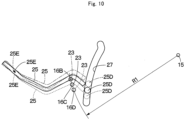
- Fig. 10 shows a state where the gate lock lever 25 is displaced in three states following a displacement of the height position of the control lever 19.
- the gate lock lever 25 is displaced to an intermediate position as shown by a solid line
- the gate lock lever 25 is displaced to an upper position as shown by a dashed-dotted line
- the gate lock lever 25 is displaced to a lower position as shown by a broken line.
- the positioning pin 23 of the height adjusting mechanism 21 moves on a circular arc-shaped path centering on the support shaft 15 together with the rotational frame 17.
- the gate lock lever 25 is rotatably attached via the first shaft body 17D to the rotational frame 17, and the second shaft body 25D disposed in the gate lock lever 25 is engaged to the guide groove 27 of the guide plate 26. Therefore, the movement of the second shaft body 25D is restricted by a shape of the guide groove 27.
- the guide groove 27 restricts the movement of the second shaft body 25D following a change in a position of the rotational frame 17 by the height adjusting mechanism 21 centering on the support shaft 15 to suppress a change in a height position of the gripping part 25E of the gate lock lever 25.
- the gate lock lever 25 can smoothly be operated from the lock releasing position to the locking position, and even in a case where the height position of the control lever 19 is adjusted, the operability to the gate lock lever 25 can be maintained to be good.
- a groove shape of the guide groove 27 corresponds to a moving path drawn by the second shaft body 25D at the time of moving the control lever 19 in the direction of widening the entrance passage 9A by the control lever moving mechanism 29.
- the constant position in which the gripping part 25E of the gate lock lever 25 is kept during the time of adjusting the height position of the control lever 19 is not limited to one point but, for example, when an operator grips the gripping part 25E in a state where the gate lock lever 25 is displaced to the intermediate position, is defined as a range in which an operator can accommodate the gripping part 25E in hand without changing the posture.
- the left console device 13 positioned on the entrance passage 9A-side for getting in/off the operator's seat 12 includes: the support shaft 15 disposed in the seat base 11 to which the operator's seat 12 is attached; the rotational frame 17 that is supported to be rotatable in the upper-lower direction on the support shaft 15 and to which the control lever 19 is attached; and the height adjusting mechanism 21 for adjusting the position of the rotational frame 17 in the rotating direction centering on the support shaft 15, and the gate lock lever 25 includes: the base plate 25A that is supported to be rotatable on the first shaft body 17D disposed in the rotational frame 17 and in which the second shaft body 25D is disposed in the position different from that of the first shaft body 17D; and the lever member 25B that is disposed to be integral with the base plate 25A and is provided with the gripping part 25E for the gripping of an operator, wherein the seat base 11 is provided with the guide plate 26 rotatable in the front-back direction
- the rotational frame 17 rotates in the upper-lower direction centering on the support shaft 15 together with the gate lock lever 25.
- the movement of the second shaft body 25D disposed on the base plate 25A of the gate lock lever 25 is restricted by the guide groove 27 of the guide plate 26.
- the left console device 13 is provided with the control lever moving mechanism 29 that rotates the rotational frame 17 to which the control lever 19 is attached, upward together with the gate lock lever 25 when the gate lock lever 25 is displaced to the locking position, and a groove shape of the guide groove 27 corresponds to the moving path drawn by the second shaft body 25D when the rotational frame 17 rotates upward by the control lever moving mechanism 29.
- the guide plate 26 is provided with the second guide groove 28 formed adjacent to the guide groove 27, and the control lever moving mechanism 29 is provided with the rotational bracket 16 in which the third shaft body 16H engaged to the second guide groove 28 is formed and that is supported on the support shaft 15 in the state of being rotatable in the upper-lower direction, and a connecting part for connection between the rotational bracket 16 and the rotational frame 17, wherein the guide groove 27 and the second guide groove 28 are arranged on the circular arcs different in a radius centering on the support shaft 15.
- the control lever 19 when the control lever 19 is caused to rotate upward by using the control lever moving mechanism 29, the second shaft body 25D disposed in the gate lock lever 25 and the third shaft body 16H disposed in the rotational bracket 16 can move in the circular arc-shaped path centering on the support shaft 15.
- the control lever 19 and the gate lock lever 25 can be rotated upward in a state of being associated with each other, making it possible to move the control lever 19 and the gate lock lever 25 in the direction (to the upper limit position) of widening the entrance passage 9A, improving the workability.
- the left console device 13 positioned on the entrance passage 9A-side is provided with the gate lock lever 25, the control lever moving mechanism 29 and the like.
- the present invention is not limited thereto but in a hydraulic excavator in which a right front part of a floor member serves as an entrance passage, a right console device positioned on an entrance passage side may be provided with a gate lock lever, a control lever moving mechanism and the like.
- a height adjusting hole in which the positioning pin 23 in the height adjusting mechanism 21 is inserted comprises three holes disposed in the rotational bracket 16.
- the present invention is not limited thereto but for example, two, four or more height adjusting holes may be provided.
- the hydraulic excavator 1 provided with the lower traveling structure 2 of a crawler type is shown as an example of the construction machine provided with the left and right console devices 13, 14.
- the present invention is not limited thereto, but may be applied widely to other construction machines, such as a hydraulic excavator provided with a lower traveling structure of a wheel type.
Landscapes
- Engineering & Computer Science (AREA)
- Mining & Mineral Resources (AREA)
- Civil Engineering (AREA)
- General Engineering & Computer Science (AREA)
- Structural Engineering (AREA)
- General Physics & Mathematics (AREA)
- Physics & Mathematics (AREA)
- Automation & Control Theory (AREA)
- Mechanical Engineering (AREA)
- Transportation (AREA)
- Aviation & Aerospace Engineering (AREA)
- Operation Control Of Excavators (AREA)
- Component Parts Of Construction Machinery (AREA)
Abstract
Description
- The present invention relates to construction machines such as a hydraulic excavator provided with console devices on both left and right sides of an operator's seat.
- A hydraulic excavator representative of a construction machine is provided with an automotive vehicle body composed of a lower traveling structure and an upper revolving structure, and a working mechanism disposed on the front side of the upper revolving structure. A cab for defining an operator's room therein is disposed on the front left side of the upper revolving structure. An operator's seat is disposed within the cab, and console devices each provided with a control lever are arranged on both sides of the operator's seat in the left-right direction. An operator sits on the operator's seat from an entrance formed on a left side surface of the cab through an entrance passage on a floor plate and operates the left and right control levers. Actuators for a revolving operation of the upper revolving structure and an operation of the working mechanism are controlled in response to operations to the control levers.
- A gate lock lever is disposed in the left console device on the entrance passage side out of the left and right console devices. This gate lock lever is operable to control supply of a pilot pressure to the control lever and is displaced to a locking position for prohibiting the operation of the actuator regardless of the operation of the control lever and a lock releasing position for allowing the operation of the actuator in response to the operation of the control lever. When the gate lock lever is displaced to the locking position, the entrance passage is released, and when the gate lock lever is displaced to the lock releasing position, the entrance passage is blocked out. Because of this configuration, when an operator or the like goes through the released entrance, even if he or she comes in contact with the control lever in error, the actuator can be prevented from inadvertently being operated.
- Incidentally, operators of various physiques are seated on the operator's seat. Therefore, there is known a hydraulic excavator in which a height of the console device provided with the control lever is changed, thereby enabling each height position of the left and right control levers to be adjusted relative to the operator's seat, for enabling the operator to operate the control lever in a comfortable posture (Patent Document 1). Further, there is known a hydraulic excavator in which in order that an operator of a large physique can smoothly go through the entrance passage from the entrance of the cab to the operator's seat, one of the console devices positioned on the entrance passage side is made movable in a direction of widening the entrance passage (backward) (Patent Document 2).
-
- Patent Document 1:
Japanese Patent Laid-Open No. 2018-168566 A - Patent Document 2:
Japanese Patent Laid-Open No. 2012-127137 A - According to
Patent Document 1, however, the mechanism for moving the console device is not disposed and the entrance passage is narrowed by the console device. Therefore, it is difficult for an operator to go through the entrance passage smoothly. On the other hand, according toPatent Document 2, since the mechanism for adjusting the height position of the control lever relative to the operator's seat is not disposed, it becomes difficult for the operators of various physiques to operate the control lever in a comfortable posture. - Therefore, it is considered to incorporate a mechanism that can move in a direction of widening the entrance and a mechanism (height adjusting mechanism) that adjusts the height position of the control lever relative to the operator's seat into the console device on the entrance passage side. In this case, since the gate lock lever is disposed in the console device on the entrance passage side, the gate lock lever is changed in a position in association with the movement of the console device of which a position is changed by the height adjusting mechanism. When the height position of the control lever is adjusted by the height adjusting mechanism, in a case where the height position of the gate lock lever is changed, there is a problem that an operator feels uncomfortable when the operator grips a gripping part of the gate lock lever. Further, since the gate lock lever is designed to prohibit the operation of the actuator, it is preferable that the gate lock lever is always in the same position, but when the position is changed by the height adjusting mechanism, there occurs a problem that operability to the gate lock lever deteriorates.
- An object of the present invention is to provide a construction machine that can maintain the operability to a gate lock lever to be good even in a case where a height position of a control lever is adjusted relative to an operator's seat.
- A construction machine according to the present invention comprises: an operator's seat; a console device provided with an control lever for operating an actuator; and a gate lock lever that is disposed in the console device and is displaced to a locking position for prohibiting an operation of the actuator in response to an operation of the control lever and a lock releasing position for allowing the operation of the actuator in response to the operation of the control lever, characterized in that the console device includes: a support shaft disposed in a seat base to which the operator's seat is attached; a rotational frame that is supported to be rotatable in an upper-lower direction on the support shaft and to which the control lever is attached; and a height adjusting mechanism for adjusting a position of the rotational frame in a rotating direction centering on the support shaft, and the gate lock lever includes: a base plate that is supported to be rotatable on a first shaft body disposed in the rotational frame and in which a second shaft body is disposed in a position different from that of the first shaft body, and a lever member that is disposed to be integral with the base plate and is provided with a gripping part for the gripping of an operator, wherein the seat base is provided with a guide member rotatable in a front-back direction of the operator's seat, the guide member being provided with a guide groove formed for engagement of the second shaft body of the gate lock lever, and the guide groove restricting a movement of the second shaft body following a change in a position of the rotational frame by the height adjusting mechanism in the rotating direction centering on the support shaft to suppress a change in a height position of the gripping part of the lever member.
- According to the present invention, when the height adjustment of the control lever is performed and the rotational frame rotates in the upper-lower direction centering on the support shaft, the movement of the second shaft body disposed on the base plate of the gate lock lever is restricted by the guide groove of the guide member. With this configuration, a change in the height position of the gripping part of the gate lock lever can be suppressed.
-
-
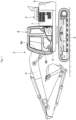
Fig. 1 is a left side view showing a hydraulic excavator according to an embodiment in the present invention. -
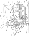
Fig. 2 is a perspective view showing an operator's seat, console devices, a gate lock lever and the like. -
Fig. 3 is a left side view showing a state where a control lever is displaced to an intermediate height by a height adjusting mechanism. -
Fig. 4 is an exploded perspective view showing a support shaft, a rotational frame, the gate lock lever, the control lever, a guide plate and the like. -
Fig. 5 is a left side view showing a state where the control lever is displaced to a maximum height by the height adjusting mechanism. -
Fig. 6 is a left side view showing a state where the control lever is displaced to a minimum height by the height adjusting mechanism. -
Fig. 7 is a left side view showing an initial state of a jumping-up motion of the control lever. -
Fig. 8 is a left side view showing a state where the control lever is moved halfway through an upper limit position. -
Fig. 9 is a left side view showing a state where the control lever is moved to the upper limit position. -
Fig. 10 is a schematic diagram showing displacements of a positioning pin, a second shaft body and a gripping part of the gate lock lever at the height adjusting of the control lever. - Hereinafter, an explanation will be in detail made of a construction machine according to an embodiment in the present invention with reference to the accompanying drawings by taking a case of being applied to a hydraulic excavator as an example. It should be noted that an explanation will be made of the present embodiment in such a manner that a traveling direction of the hydraulic excavator is defined as a front-back direction, and a direction perpendicular to the traveling direction of the hydraulic excavator is defined as a left-right direction.
- In the figure, a
hydraulic excavator 1 representative of a construction machine is provided with an automotivelower traveling structure 2 of a crawl type in the front-back direction and an upper revolvingstructure 3 that is mounted on thelower traveling structure 2 to be capable of revolving thereon. Thelower traveling structure 2 and theupper revolving structure 3 configure a vehicle body in thehydraulic excavator 1. Aworking mechanism 4 is disposed on the front side of the upper revolvingstructure 3 to be capable of tilting and lifting thereto. Thehydraulic excavator 1 travels in the working site by thelower traveling structure 2, and tilts and lifts theworking mechanism 4 while revolving the upper revolvingstructure 3, thus performing an excavating work of earth and sand, or the like. - The upper revolving
structure 3 is provided with a revolvingframe 5 as a base. Acounterweight 6 is disposed on the rear side of the revolvingframe 5 to act as a weight balance to theworking mechanism 4. Mounted equipment devices (none of them are shown) of an engine, a hydraulic pump, a heat exchanger and the like are mounted on the revolvingframe 5 to be positioned in the front side to thecounterweight 6. The mounted equipment devices are covered with anexterior cover 7 disposed on the revolvingframe 5. Acab 8 is disposed on the front left side of the upper revolvingstructure 3 to define an operator's room therein. - The
cab 8 rises upward from the revolvingframe 5 to be formed in a boxy shape and the operator's room is defined in the inside of thecab 8. Anentrance 8A for an operator to get in/off thecab 8 and adoor 8B for opening/closing theentrance 8A are arranged on the left side surface of thecab 8. A lower side of thecab 8 is covered with afloor member 9. Thefloor member 9 configures a floor plate of thecab 8 and as shown inFig. 2 , is formed as a rectangular plate body elongated in the front-back direction. An operator'sseat 12, aleft console device 13, aright console device 14 and agate lock lever 25, which will be described later, and the like are arranged in the operator's room in thecab 8, and a left front part of thefloor member 9 serves as anentrance passage 9A for the operator to move (getting in/off) between theentrance 8A of thecab 8 and the operator'sseat 12. - An operator's
seat support platform 10 is disposed in an intermediate position of thefloor member 9 in the front-back direction. The operator'sseat support platform 10 includes aseating 10A fixed on thefloor member 9, aposition adjusting mechanism 10B disposed on theseating 10A and aseat base 11 disposed on theposition adjusting mechanism 10B. Since operators of various physiques sit on the operator'sseat 12, an optimal position of the control lever differs depending on the operator. Therefore, disposing theposition adjusting mechanism 10B on the operator'sseat support platform 10 enables the operator'sseat 12, theleft console device 13 and theright console device 14 to be adjusted in a position in the front-back direction and in the upper-lower direction. - The
seat base 11 is located above theposition adjusting mechanism 10B and configures a base for attaching the operator'sseat 12, theleft console device 13, theright console device 14 and the like. Theseat base 11 is formed in a flat boxy shape as a whole and as shown inFig. 4 , a leftrear projection plate 11A that projects upward is disposed on a left rear part of theseat base 11 and asupport shaft 15 to be described later is disposed on the leftrear projection plate 11A. On the other hand, a right rear projection plate (not shown) is disposed on a right rear part of theseat base 11 in a position symmetrical to the leftrear projection plate 11A in the left-right direction and a support shaft (not shown) is disposed on the right rear projection plate. - A left
front projection plate 11B that projects downward is disposed on a left front part of theseat base 11. Further, a leftintermediate projection plate 11C that projects downward is disposed, which is in a portion closer to the leftrear projection plate 11A, in an intermediate part of theseat base 11 in the front-back direction. Aguide plate shaft 11D, astopper shaft 11E and alower engagement pin 11F are arranged on a lower end side of the leftfront projection plate 11B at intervals in the front-back direction and respectively project to the left side from the leftfront projection plate 11B. - A
guide plate 26 to be described later is attached to a projection end side of theguide plate shaft 11D to be rotatable in the front-back direction. Thestopper shaft 11E holds theguide plate 26 to a lever height adjusting posture as shown inFig. 3 due to theguide plate 26 abutting on thestopper shaft 11E. One end of acoil spring 31 to be described later is engaged to thelower engagement pin 11F. On the other hand, a lowergas spring pin 11G is fixed on a lower end side of the leftintermediate projection plate 11C and projects to the left side from the leftintermediate projection plate 11C. A bottom side of agas spring 30 to be described later is attached to the lowergas spring pin 11G. - The operator's
seat 12 is disposed on theseat base 11 of the operator'sseat support platform 10. Theleft console device 13 provided with thecontrol lever 19 is located on the left side of the operator'sseat 12 and theright console device 14 provided with thecontrol lever 20 is located on the right side of the operator'sseat 12. An operator sitting on the operator'sseat 12 operates the left and right control levers 19, 20, thereby controlling the operations of actuators of the revolving motor for driving the upper revolvingstructure 3, the hydraulic cylinder for driving theworking mechanism 4, and the like. - Next, an explanation will be made of the
left console device 13 and theright console device 14 according to the present embodiment. Theleft console device 13 and theright console device 14 are formed to be substantially symmetrical to each other in the left-right direction. Therefore, hereinafter an explanation will be made of the details of the configuration of theleft console device 13 as one of the console devices positioned on theentrance passage 9A-side, and in theright console device 14, components corresponding to those in theleft console device 13 are referred to as the identical numerals and an explanation thereof is omitted. - The
left console device 13 is located on the left side of the operator'sseat 12 and is provided with thecontrol lever 19 for operating the actuator. Theleft console device 13 configures one of the console devices positioned on theentrance passage 9A-side of thefloor member 9. Theleft console device 13 includes thesupport shaft 15, arotational bracket 16, arotational frame 17, thegate lock lever 25, theguide plate 26 and the like. - The
support shaft 15 is disposed on a left rear part of theseat base 11 and projects to the left side. Thesupport shaft 15 is formed in a columnar shape and supports therotational bracket 16 and therotational frame 17 to be rotatable relative to theseat base 11. - The
rotational bracket 16 is disposed adjacent to the left side of theseat base 11. As shown inFig. 4 , therotational bracket 16 is formed in a plate shape extending in the front-back direction as a whole. A shaft throughhole 16A is formed in a rear upper side of therotational bracket 16 and thesupport shaft 15 is inserted via a bearing in the shaft throughhole 16A. With this configuration, therotational bracket 16 is designed to be rotatable in the upper-lower direction centering on thesupport shaft 15. A plurality (for example, three holes) ofheight adjusting holes rotational bracket 16. Theheight adjusting holes hole 16A, and apositioning pin 23 to be described later is fitted selectively into any one of theheight adjusting holes - An upper
gas spring pin 16E is disposed in an intermediate part of therotational bracket 16 in the longitudinal direction (front-back direction). The uppergas spring pin 16E is formed in a stepped columnar shape and projects to the left side from therotational bracket 16. A rod side of thegas spring 30 is attached to be rotatable on a projection end of the uppergas spring pin 16E. In addition, Ashaft attachment plate 16G is attached via aspacer 16F on the front side of therotational bracket 16. Athird shaft body 16H in a stepped columnar shape is disposed on theshaft attachment plate 16G to project to the left side and a projection end of thethird shaft body 16H is engaged to asecond guide groove 28 of theguide plate 26. - The
rotational frame 17 is disposed adjacent to the left side of therotational bracket 16. Therotational frame 17 is formed in a frame shape extending in the front-back direction as a whole. A shaft throughhole 17A is formed in a rear side of therotational frame 17 and thesupport shaft 15 is inserted via a bearing in the shaft throughhole 17A. With this configuration, therotational frame 17 is designed to be rotatable in the upper-lower direction centering on thesupport shaft 15. A rear-side attachment part 17B in a square cylinder shape is disposed on the upper side of the shaft throughhole 17A in therotational frame 17. An armrest 18 on which an operator sitting on the operator'sseat 12 places an operator's arm is attached to the rear-side attachment part 17B. - A boxy front-
side attachment part 17C is disposed on the front side of therotational frame 17. Thecontrol lever 19 is attached to the front-side attachment part 17C and apin support case 22 configuring part of aheight adjusting mechanism 21 is disposed on the front end of the front-side attachment part 17C. In addition, afirst shaft body 17D in a columnar shape is disposed to project to the left side on the front-side attachment part 17C and abase plate 25A of thegate lock lever 25 is rotatably supported on thefirst shaft body 17D. - The
control lever 19 is disposed in theleft console device 13 and thecontrol lever 20 is disposed in theright console device 14. The left and right control levers 19, 20 are operated by an operator to control the operations of actuators such as the revolving motor for performing a revolving operation of the upper revolvingstructure 3, the hydraulic cylinder configuring part of the workingmechanism 4 and the like. Thecontrol lever 19 includes a pilot valve of a pressure reducing valve type (not shown) attached to the front-side attachment part 17C of therotational frame 17, and alever part 19A that extends upward from the pilot valve and is gripped by an operator. Thecontrol lever 20 on the right side also includes a pilot valve of a pressure reducing valve type (not shown), and alever part 20A that is gripped by an operator. - The
height adjusting mechanism 21 is disposed on the front side of theleft console device 13 to adjust a height position of thecontrol lever 19 relative to the operator'sseat 12 in a stepwise fashion (for example, in three stages). It should be noted that a height adjusting mechanism is disposed also on the front side of theright console device 14 to adjust a height position of thecontrol lever 20 and the height adjusting mechanism on the right side is configured to be similar to theheight adjusting mechanism 21 on the left side. Therefore, hereinafter, an explanation will be made of theheight adjusting mechanism 21 on the left side and an explanation of the height adjusting mechanism on the right side is omitted. As shown inFig. 4 , theheight adjusting mechanism 21 includes the threeheight adjusting holes pin support case 22, thepositioning pin 23 and arelease lever 24. - The
pin support case 22 is disposed on the front end of the front-side attachment part 17C configuring part of therotational frame 17. Thepin support case 22 is formed in a square cylinder shape extending in the upper-lower direction and a pin throughhole 22A is disposed on the lower end side of thepin support case 22 to penetrate therethrough in the left-right direction. In addition, a lever through hole (not shown) is disposed on the front surface of thepin support case 22 to be positioned closer to the upper side than the pin throughhole 22A and penetrate therethrough in the front-back direction. - The
positioning pin 23 is supported to be movable on thepin support case 22. Thepositioning pin 23 is formed in a columnar shape extending in the left-right direction and is inserted in the pin throughhole 22A disposed in thepin support case 22 to be movable axially (in the left-right direction) . Thepositioning pin 23 is urged in a projecting direction toward therotational bracket 16 by an urgent member (not shown) of a spring or the like. In addition, when therotational frame 17 is rotated centering on thesupport shaft 15, thepositioning pin 23 is selectively inserted in any one of the threeheight adjusting holes rotational bracket 16. - For example, as shown in
Fig. 5 , when thepositioning pin 23 is inserted in theheight adjusting hole 16B, the height position of thecontrol lever 19 is set to a maximum height. In addition, as shownFig. 6 , when thepositioning pin 23 is inserted in theheight adjusting hole 16D, the height position of thecontrol lever 19 is set to a minimum height. Further, as shownFig. 3 , when thepositioning pin 23 is inserted in theheight adjusting hole 16C, the height position of thecontrol lever 19 is set to an intermediate height as intermediate between the maximum height and the minimum height. In this way, when therotational frame 17 to which thecontrol lever 19 is attached is locked to any height position of theheight adjusting holes control lever 19 relative to the operator'sseat 12 is adjusted in three stages. In this state, therotational bracket 16 and therotational frame 17 are connected, and a connecting part for connecting therotational bracket 16 and therotational frame 17 is configured of thepositioning pin 23 and theheight adjusting holes - The
release lever 24 is positioned closer to the upper side than thepositioning pin 23 to be rotatably disposed in thepin support case 22. Therelease lever 24 is configured of a bar-shaped body extending in the front-back direction and is supported to be rotatable in a lever through hole (not shown) of thepin support case 22. Therelease lever 24 projects forward from thepin support case 22, and a projection end of therelease lever 24 serves as a control part extending in the left-right direction from the front end of the left console device 13 (refer toFig. 2 ). An operator sitting on the operator'sseat 12 operates the control part of therelease lever 24 to rotate therelease lever 24. - A conversion member (not shown) that converts a rotational motion of the
release lever 24 to a linear motion in an axial direction of thepositioning pin 23 is disposed in the inside of thepin support case 22. Accordingly, when an operator operates therelease lever 24 for rotation, the rotational motion of therelease lever 24 is converted into the linear motion in the axial direction of thepositioning pin 23 by the conversion member. As a result, thepositioning pin 23 inserted in any one of theheight adjusting holes rotational bracket 16 leaves theheight adjusting hole rotational frame 17 is released and therotational frame 17 can rotate in the upper-lower direction centering on thesupport shaft 15 together with thecontrol lever 19. - Next, an explanation will be made of the
gate lock lever 25 disposed in theleft console device 13. - The
gate lock lever 25 is disposed in theleft console device 13, which is positioned on theentrance passage 9A-side for getting in/off the operator'sseat 12, out of theleft console device 13 and theright console device 14. Thegate lock lever 25 is operated by an operator or the like to be displaced to a locking position as shown inFig. 7 and a lock releasing position as shown inFig. 3 . - The
gate lock lever 25 maintains the locking position as shown inFig. 7 . When thegate lock lever 25 releases theentrance passage 9A-side, the supply of the pilot pressure to the control levers 19, 20 is stopped. With this configuration, regardless of the operations to the left and right control levers 19, 20 the operation of the actuator is prohibited, and when an operator or the like goes through theentrance passage 9A, even if the operator comes in contact with thecontrol lever 19 or the like in error, the actuator can be prevented from operating inadvertently. - On the other hand, the
gate lock lever 25 maintains the lock releasing position as shown inFig. 3 , and when thegate lock lever 25 blocks out theentrance passage 9A, the supply of the pilot pressure to the control levers 19, 20 is made possible. With this configuration, the operation of the actuator in response to the operations of the left and right control levers 19, 20 is allowed. - Here, as shown in
Fig. 4 , thegate lock lever 25 includes thebase plate 25A in a flat plate shape, and alever member 25B fixed to be integral with thebase plate 25A. A shaft throughhole 25C is disposed on the upper side of thebase plate 25A to penetrate therethrough in the plate thickness direction, and the shaft throughhole 25C is inserted in thefirst shaft body 17D disposed to project on the rotational frame 17 (front-side attachment part 17C) . Accordingly, thegate lock lever 25 is rotatably supported via thefirst shaft body 17D on therotational frame 17 and is displaced to the locking position and the lock releasing position centering on thefirst shaft body 17D. Asecond shaft body 25D is disposed on the lower side of thebase plate 25A. Thesecond shaft body 25D is formed in a columnar shape extending in the left-right direction and projects to the left side from thebase plate 25A. Thesecond shaft body 25D is movably engaged to aguide groove 27 of theguide plate 26. - The
lever member 25B is fixed on thebase plate 25A by using the means of welding or the like. Thelever member 25B is formed by performing bending work to a round bar material, for example, and thelever member 25B projects forward in such a manner as to block out theentrance passage 9A when thegate lock lever 25 is in the lock releasing position (position inFig. 3 ). A tip end side of thelever member 25B becomes agripping part 25E to be gripped by an operator or the like at the time of operating thegate lock lever 25 and agrip 25F is attached to thegripping part 25E. - The
guide plate 26 as a guide member is rotatably attached to theseat base 11. As shown inFig. 3 andFig. 4 , theguide plate 26 is formed in a flat plate shape extending in the upper-lower direction and is provided with aguide groove 27 and asecond guide groove 28. Here, a shaft throughhole 26A is disposed on the lower side of theguide plate 26 to penetrate therethrough in the plate thickness direction, and the shaft throughhole 26A is inserted via a bearing in theguide plate shaft 11D disposed in the leftfront projection plate 11B of theseat base 11. - With this configuration, the
guide plate 26 is rotatably supported in the front-back direction centering on theguide plate shaft 11D, and at the time of adjusting a height of thecontrol lever 19 by theheight adjusting mechanism 21, maintains a lever height adjusting posture as shown inFig. 3 ,Fig. 5 andFig. 6 . On the other hand, theguide plate 26, at the time of moving thecontrol lever 19 upward (in a direction of widening theentrance passage 9A) by a controllever moving mechanism 29 to be described later, maintains a lever moving posture as shown inFig. 7 to Fig. 9 . In this way, theguide plate 26 is displaced to the lever height adjusting posture and the lever moving posture centering on theguide plate shaft 11D. - The
guide groove 27 is disposed in theguide plate 26 to be positioned closer to the upper side than the shaft throughhole 26A. Thesecond shaft body 25D disposed on thebase plate 25A of thegate lock lever 25 is engaged to be movable to theguide groove 27. With this configuration, when therotational frame 17 to which thecontrol lever 19 is attached rotates centering on thesupport shaft 15 together with thegate lock lever 25 by theheight adjusting mechanism 21, the movement of thesecond shaft body 25D is restricted along a shape of theguide groove 27. - Here, the
guide groove 27 is disposed to form a circular arc of a radius R2 centering on thesupport shaft 15 when theguide plate 26 assumes the lever moving posture (posture inFig. 7 to Fig. 9 ) . Anupper engagement groove 27A is disposed on an upper end of theguide groove 27. Theupper engagement groove 27A is located in a portion away from thesupport shaft 15 by more than the radius R2 of theguide groove 27 and is communicated with an upper end side of theguide groove 27. When thecontrol lever 19 moves to the upper limit position (jumping-up position) as shown inFig. 9 by a controllever moving mechanism 29 to be described later, thesecond shaft body 25D of the gate lock lever 25 (base plate 25A) is engaged to theupper engagement groove 27A from theguide groove 27. As a result, the movement of thesecond shaft body 25D is stopped and thecontrol lever 19 and thegate lock lever 25 maintain the upper limit position inFig. 9 . - The
second guide groove 28 is disposed adjacent to theguide groove 27 on theguide plate 26. Thesecond guide groove 28 configures part of the controllever moving mechanism 29. Thethird shaft body 16H disposed in the rotational bracket 16 (shaft attachment plate 16G) is movably engaged to thesecond guide groove 28. Thesecond guide groove 28, because of moving thecontrol lever 19 upward by the controllever moving mechanism 29, restricts the movement of thethird shaft body 16H when therotational bracket 16 rotates upward centering on thesupport shaft 15. - Here, the
second guide groove 28 is disposed to form a circular arc of a radius R3 centering on thesupport shaft 15 when theguide plate 26 assumes the lever moving posture. In this case, the radius R3 of a circular arc shape of thesecond guide groove 28 is set to be smaller than the radius R2 of the circular arc shape of the guide groove 27 (R2 > R3) . In this way, when theguide plate 26 assumes the lever moving posture, theguide groove 27 and thesecond guide groove 28 are respectively arranged on circular arcs different in a radius centering on thesupport shaft 15. - A
lower engagement groove 28A is disposed on a lower end of thesecond guide groove 28. Thelower engagement groove 28A is located in a portion away from thesupport shaft 15 by more than the radius R3 of thesecond guide groove 28 and is communicated with a lower end side of thesecond guide groove 28. When thethird shaft body 16H of therotational bracket 16 is engaged to thelower engagement groove 28A, theguide plate 26 maintains the lever height adjusting posture as shown inFig. 3 or the like. In addition, when thethird shaft body 16H is engaged from thelower engagement groove 28A to thesecond guide groove 28, theguide plate 26 transfers from the lever height adjusting posture to the lever moving posture. - An
upper engagement pin 26B is disposed on a portion, which is adjacent to thelower engagement groove 28A, in theguide plate 26. Theupper engagement pin 26B projects to the left side from theguide plate 26 and the other end of thecoil spring 31 is engaged to a projection end of theupper engagement pin 26B. - The control
lever moving mechanism 29 is disposed in theleft console device 13. The controllever moving mechanism 29 is caused to move thecontrol lever 19 upward as a direction of widening theentrance passage 9A centering on thesupport shaft 15 together with thegate lock lever 25 when thegate lock lever 25 is displace to the locking position. The controllever moving mechanism 29 includes therotational bracket 16, therotational frame 17, thegate lock lever 25, theguide plate 26, thegas spring 30 and thecoil spring 31. - The
gas spring 30 is disposed between theseat base 11 and therotational bracket 16. A bottom side of thegas spring 30 is rotatably attached to the lowergas spring pin 11G disposed in the seat base 11 (leftintermediate projection plate 11C), and a rod side of thegas spring 30 is rotatably attached to the uppergas spring pin 16E disposed in therotational bracket 16. With this configuration, thegas spring 30 urges therotational bracket 16 in a direction of being rotated upward centering on thesupport shaft 15. - The
coil spring 31 is disposed between theseat base 11 and theguide plate 26. Thecoil spring 31 is composed of a tension spring, and one end of thecoil spring 31 is engaged to thelower engagement pin 11F of theseat base 11 and the other end of thecoil spring 31 is engaged to theupper engagement pin 26B of theguide plate 26. Thecoil spring 31 urges theguide plate 26 in a direction of abutting on thestopper shaft 11E centering on theguide plate shaft 11D. - The
left console device 13 in thehydraulic excavator 1 according to the present embodiment has the configuration as described above, and next, an explanation will be made of the operation (jumping-up operation) of moving thecontrol lever 19 upward (in a direction of widening theentrance passage 9A) by the controllever moving mechanism 29. - At the time of performing the jumping-up operation of the
control lever 19 by the controllever moving mechanism 29, for example, thegate lock lever 25 in the lock releasing position inFig. 3 is rotated upward centering on thefirst shaft body 17D disposed to project on therotational frame 17. With this configuration, as shown inFig. 7 , thesecond shaft body 25D disposed in thegate lock lever 25 presses theguide plate 26 forward against thecoil spring 31. Therefore, theguide plate 26 rotates forward centering on theguide plate shaft 11D to be displaced to the lever moving posture. At this time, thethird shaft body 16H disposed to project on therotational bracket 16 leaves thelower engagement groove 28A of theguide plate 26 and is engaged to thesecond guide groove 28. - Therefore, the
rotational bracket 16 rotates upward centering on thesupport shaft 15 by thegas spring 30. At this time, since thepositioning pin 23 in theheight adjusting mechanism 21 is engaged to any one of theheight adjusting holes 16B to 16D (for example, theheight adjusting hole 16C), therotational frame 17 and therotational bracket 16 are united. Accordingly, therotational bracket 16, therotational frame 17, thecontrol lever 19 and thegate lock lever 25 integrally rotates upward centering on thesupport shaft 15. - When the
guide plate 26 is displaced to the lever moving posture, theguide groove 27 and thesecond guide groove 28 of theguide plate 26 are respectively arranged on circular arcs different in a radius centering on thesupport shaft 15. Therefore, thesecond shaft body 25D of thegate lock lever 25 smoothly moves upward along theguide groove 27, and thethird shaft body 16H of therotational bracket 16 can smoothly move upward along thesecond guide groove 28. As a result, thecontrol lever 19 and thegate lock lever 25 can be moved to the upper limit position in a state of being associated with each other, improving the workability. - In addition, as shown in
Fig. 9 , when thesecond shaft body 25D of thegate lock lever 25 is engaged to theupper engagement groove 27A disposed on the upper end side of theguide groove 27, the movement of thesecond shaft body 25D is stopped, and thecontrol lever 19 and thegate lock lever 25 are stopped in the upper limit position (jumping-up position). With this configuration, in a state where thegate lock lever 25 is set in the locking position, thecontrol lever 19 and thegate lock lever 25 are moved in the direction of widening theentrance passage 9A, making it possible to secure a space of theentrance passage 9A to be large. - In this way, when the
control lever 19 and thegate lock lever 25 are moved to the upper limit position, thesecond shaft body 25D of thegate lock lever 25 is engaged to theupper engagement groove 27A disposed on the upper end side of theguide groove 27. Therefore, therotational frame 17 connected via thefirst shaft body 17D to thegate lock lever 25 is interrupted from rotating centering on thesupport shaft 15. Accordingly, thepositioning pin 23 of theheight adjusting mechanism 21 attached to therotational frame 17 cannot be removed from/inserted in theheight adjusting holes rotational bracket 16. That is, in the present embodiment, in a state where thecontrol lever 19 and thegate lock lever 25 are moved to the upper limit position, it is possible to prohibit the adjustment of the height position of thecontrol lever 19 relative to the operator'sseat 12. - As a result, in a state where the
control lever 19 and thegate lock lever 25 are moved to the upper limit position, thecontrol lever 19 can be prevented from being set to an unintentional height position due to an operator or the like in error contacting therelease lever 24 of theheight adjusting mechanism 21 or the like. Accordingly, in a state where thegate lock lever 25 is displaced to the lock releasing position, the operator sitting on the operator'sseat 12 can accurately adjust the height position of thecontrol lever 19. - Next, an explanation will be made of the height adjusting operation of adjusting the height position of the
control lever 19 relative to the operator'sseat 12 by theheight adjusting mechanism 21. - At the time of performing the height adjusting operation of the
control lever 19 by theheight adjusting mechanism 21, for example, thegate lock lever 25 in the upper limit position is rotated downward (forward) centering on thefirst shaft body 17D. As a result, as shown inFig. 8 , thesecond shaft body 25D leaves theupper engagement groove 27A of theguide groove 27 and is engaged to theguide groove 27. In this state, thegate lock lever 25 is pressed downward against thegas spring 30. - With this configuration, the
rotational bracket 16, therotational frame 17, thecontrol lever 19 and thegate lock lever 25 integrally rotate downward centering on thesupport shaft 15. In addition, as shown inFig. 7 , when thethird shaft body 16H of therotational bracket 16 reaches the lower end of thesecond guide groove 28 in theguide plate 26, thegate lock lever 25 is rotated further downward (forward) centering on thefirst shaft body 17D. - With this configuration, the
second shaft body 25D of thegate lock lever 25 presses theguide plate 26 backward, and theguide plate 26 rotates backward centering on theguide plate shaft 11D. In this way, as shown inFig. 3 , thethird shaft body 16H of therotational bracket 16 is engaged to thelower engagement groove 28A from thesecond guide groove 28. At this time, theguide plate 26 abuts on thestopper shaft 11E of theseat base 11 by thecoil spring 31 to maintain the lever height adjusting posture. - In this way, in a state where the
guide plate 26 maintains the lever height adjusting posture, therotational bracket 16 is fixed via theguide plate 26 on theseat base 11. In this state, the height adjustment of thecontrol lever 19 relative to the operator'sseat 12 is performed by theheight adjusting mechanism 21. - For example, as shown in
Fig. 3 , in a case where thepositioning pin 23 of theheight adjusting mechanism 21 is inserted in theheight adjusting hole 16C of therotational bracket 16, an operator or the like rotates therelease lever 24 to separate thepositioning pin 23 from theheight adjusting hole 16C. With this configuration, therotational frame 17 to which thecontrol lever 19 is attached is made rotatable in the upper-lower direction centering on thesupport shaft 15. - Accordingly, when the
rotational frame 17 is caused to rotate upward and thepositioning pin 23 is inserted in theheight adjusting hole 16B, as shown inFig. 5 the height position of thecontrol lever 19 can be adjusted to the maximum height. In addition, when therotational frame 17 is caused to rotate downward and thepositioning pin 23 is inserted in theheight adjusting hole 16D, as shown inFig. 6 the height position of thecontrol lever 19 can be adjusted to the minimum height. Further, when thepositioning pin 23 is inserted in theheight adjusting hole 16C, as shown inFig. 3 the height position of thecontrol lever 19 can be adjusted to the intermediate height. - In this way, when the height position of the
control lever 19 is adjusted by theheight adjusting mechanism 21, thecontrol lever 19 attached to therotational frame 17 and thegate lock lever 25 attached via thefirst shaft body 17D to therotational frame 17 rotate together centering on thesupport shaft 15. Thegate lock lever 25 is made rotatable relative to therotational frame 17 centering on thefirst shaft body 17D, and thesecond shaft body 25D disposed in thegate lock lever 25 is engaged to theguide groove 27 of theguide plate 26 to restrict the movement. - Here,
Fig. 10 shows a state where thegate lock lever 25 is displaced in three states following a displacement of the height position of thecontrol lever 19. When thecontrol lever 19 is in the intermediate height, thegate lock lever 25 is displaced to an intermediate position as shown by a solid line, when thecontrol lever 19 is in the maximum height, thegate lock lever 25 is displaced to an upper position as shown by a dashed-dotted line and when thecontrol lever 19 is in the minimum height, thegate lock lever 25 is displaced to a lower position as shown by a broken line. - As shown in
Fig. 10 , since theheight adjusting holes 16B to 16D are arranged in a circular arc shape of a radius R1 centering on thesupport shaft 15, thepositioning pin 23 of theheight adjusting mechanism 21 moves on a circular arc-shaped path centering on thesupport shaft 15 together with therotational frame 17. On the other hand, thegate lock lever 25 is rotatably attached via thefirst shaft body 17D to therotational frame 17, and thesecond shaft body 25D disposed in thegate lock lever 25 is engaged to theguide groove 27 of theguide plate 26. Therefore, the movement of thesecond shaft body 25D is restricted by a shape of theguide groove 27. As a result, even when thegate lock lever 25 is displaced to the intermediate position, the upper position and the lower position, a change in a height position of thegripping part 25E of the gate lock lever 25 (lever member 25B) is suppressed, making it possible to hold thegripping part 25E in a constant position. That is, theguide groove 27 restricts the movement of thesecond shaft body 25D following a change in a position of therotational frame 17 by theheight adjusting mechanism 21 centering on thesupport shaft 15 to suppress a change in a height position of thegripping part 25E of thegate lock lever 25. - Therefore, by adjusting the height position of the
control lever 19, even when thegate lock lever 25 is displaced to three positions of the intermediate position, the upper position and the lower position, an operator sitting on the operator'sseat 12 can always grip thegripping part 25E of thegate lock lever 25 without having an uncomfortable feeling in a substantially constant position by expanding his/her arm with the same posture being kept. As a result, for example, thegate lock lever 25 can smoothly be operated from the lock releasing position to the locking position, and even in a case where the height position of thecontrol lever 19 is adjusted, the operability to thegate lock lever 25 can be maintained to be good. In this case, a groove shape of theguide groove 27 corresponds to a moving path drawn by thesecond shaft body 25D at the time of moving thecontrol lever 19 in the direction of widening theentrance passage 9A by the controllever moving mechanism 29. As a result, utilizing theguide groove 27 as the moving path of thesecond shaft body 25D when thecontrol lever 19 is moved to the upper limit position, thegripping part 25E of thegate lock lever 25 can be kept in a constant position at the height adjusting of thecontrol lever 19. - It should be noted that in the present embodiment, the constant position in which the
gripping part 25E of thegate lock lever 25 is kept during the time of adjusting the height position of thecontrol lever 19 is not limited to one point but, for example, when an operator grips thegripping part 25E in a state where thegate lock lever 25 is displaced to the intermediate position, is defined as a range in which an operator can accommodate thegripping part 25E in hand without changing the posture. - In this way, in the hydraulic excavator 1 according to the present embodiment the left console device 13 positioned on the entrance passage 9A-side for getting in/off the operator's seat 12 includes: the support shaft 15 disposed in the seat base 11 to which the operator's seat 12 is attached; the rotational frame 17 that is supported to be rotatable in the upper-lower direction on the support shaft 15 and to which the control lever 19 is attached; and the height adjusting mechanism 21 for adjusting the position of the rotational frame 17 in the rotating direction centering on the support shaft 15, and the gate lock lever 25 includes: the base plate 25A that is supported to be rotatable on the first shaft body 17D disposed in the rotational frame 17 and in which the second shaft body 25D is disposed in the position different from that of the first shaft body 17D; and the lever member 25B that is disposed to be integral with the base plate 25A and is provided with the gripping part 25E for the gripping of an operator, wherein the seat base 11 is provided with the guide plate 26 rotatable in the front-back direction of the operator's seat 12, the guide plate 26 being provided with the guide groove 27 formed for engagement of the second shaft body 25D of the gate lock lever 25, and the guide groove 27 restricting the movement of the second shaft body 25D following the change in the position of the rotational frame 17 by the height adjusting mechanism 21 in the rotating direction centering on the support shaft 15 to suppress the change in the height position of the gripping part 25E of the lever member 25B.
- According to the configuration, when the adjustment of the height position relative to the operator's
seat 12 of thecontrol lever 19 is performed by theheight adjusting mechanism 21, therotational frame 17 rotates in the upper-lower direction centering on thesupport shaft 15 together with thegate lock lever 25. At this time, the movement of thesecond shaft body 25D disposed on thebase plate 25A of thegate lock lever 25 is restricted by theguide groove 27 of theguide plate 26. With this configuration, the change in the height position of thegripping part 25E of thegate lock lever 25 can be suppressed. - In the embodiment the
left console device 13 is provided with the controllever moving mechanism 29 that rotates therotational frame 17 to which thecontrol lever 19 is attached, upward together with thegate lock lever 25 when thegate lock lever 25 is displaced to the locking position, and a groove shape of theguide groove 27 corresponds to the moving path drawn by thesecond shaft body 25D when therotational frame 17 rotates upward by the controllever moving mechanism 29. According to this configuration, at the time of rotating thecontrol lever 19 upward toward the upper limit position, the change in the height position of thegripping part 25E of thegate lock lever 25 can be suppressed by utilizing theguide groove 27 as the moving path of thesecond shaft body 25D. - In the embodiment the
guide plate 26 is provided with thesecond guide groove 28 formed adjacent to theguide groove 27, and the controllever moving mechanism 29 is provided with therotational bracket 16 in which thethird shaft body 16H engaged to thesecond guide groove 28 is formed and that is supported on thesupport shaft 15 in the state of being rotatable in the upper-lower direction, and a connecting part for connection between therotational bracket 16 and therotational frame 17, wherein theguide groove 27 and thesecond guide groove 28 are arranged on the circular arcs different in a radius centering on thesupport shaft 15. - According to this configuration, when the
control lever 19 is caused to rotate upward by using the controllever moving mechanism 29, thesecond shaft body 25D disposed in thegate lock lever 25 and thethird shaft body 16H disposed in therotational bracket 16 can move in the circular arc-shaped path centering on thesupport shaft 15. As a result, thecontrol lever 19 and thegate lock lever 25 can be rotated upward in a state of being associated with each other, making it possible to move thecontrol lever 19 and thegate lock lever 25 in the direction (to the upper limit position) of widening theentrance passage 9A, improving the workability. - It should be noted that in the embodiment there is shown as an example a case where in the
hydraulic excavator 1 in which the left front part of thefloor member 9 serves as theentrance passage 9A, theleft console device 13 positioned on theentrance passage 9A-side is provided with thegate lock lever 25, the controllever moving mechanism 29 and the like. However, the present invention is not limited thereto but in a hydraulic excavator in which a right front part of a floor member serves as an entrance passage, a right console device positioned on an entrance passage side may be provided with a gate lock lever, a control lever moving mechanism and the like. - In the embodiment there is shown as an example a case where a height adjusting hole in which the
positioning pin 23 in theheight adjusting mechanism 21 is inserted comprises three holes disposed in therotational bracket 16. However, the present invention is not limited thereto but for example, two, four or more height adjusting holes may be provided. - In the embodiment, the
hydraulic excavator 1 provided with thelower traveling structure 2 of a crawler type is shown as an example of the construction machine provided with the left andright console devices -
- 9:
- FLOOR MEMBER
- 9A:
- ENTRANCE PASSAGE
- 11:
- SEAT BASE
- 12:
- OPERATOR'S SEAT
- 13:
- LEFT CONSOLE DEVICE
- 14:
- RIGHT CONSOLE DEVICE
- 15:
- SUPPORT SHAFT
- 16:
- ROTATIONAL BRACKET
- 16B, 16C, 16D:
- HEIGHT ADJUSTING HOLE (CONNECTING PART)
- 16H:
- THIRD SHAFT BODY
- 17:
- ROTATIONAL FRAME
- 17D:
- FIRST SHAFT BODY
- 19, 20:
- CONTROL LEVER
- 21:
- HEIGHT ADJUSTING MECHANISM
- 23:
- POSITIONING PIN (CONNECTING PART)
- 25:
- GATE LOCK LEVER
- 25A:
- BASE PLATE
- 25B:
- LEVER MEMBER
- 25D:
- SECOND SHAFT BODY
- 25E:
- GRIPPING PART
- 26:
- GUIDE PLATE (GUIDE MEMBER)
- 27:
- GUIDE GROOVE
- 28:
- SECOND GUIDE GROOVE
- 29:
- CONTROL LEVER MOVING MECHANISM
Claims (3)
- A construction machine comprising:an operator's seat;a console device provided with a control lever for operating an actuator; anda gate lock lever that is disposed in the console device and is displaced to a locking position for prohibiting an operation of the actuator in response to an operation of the control lever and a lock releasing position for allowing the operation of the actuator in response to the operation of the control lever, characterized in thatthe console device includes:a support shaft disposed in a seat base to which the operator's seat is attached;a rotational frame that is supported to be rotatable in an upper-lower direction on the support shaft and to which the control lever is attached; anda height adjusting mechanism for adjusting a position of the rotational frame in a rotating direction centering on the support shaft, andthe gate lock lever includes:a base plate that is supported to be rotatable on a first shaft body disposed in the rotational frame and in which a second shaft body is disposed in a position different from that of the first shaft body; anda lever member that is disposed to be integral with the base plate and is provided with a gripping part for the gripping of an operator, whereinthe seat base is provided with a guide member rotatable in a front-back direction of the operator's seat, the guide member being provided with a guide groove formed for engagement of the second shaft body of the gate lock lever, and the guide groove restricting a movement of the second shaft body following a change in a position of the rotational frame by the height adjusting mechanism in the rotating direction centering on the support shaft to suppress a change in a height position of the gripping part of the lever member.
- The construction machine according to claim 1, whereinthe console device is provided with a control lever moving mechanism that rotates the rotational frame to which the control lever is attached, upward together with the gate lock lever when the gate lock lever is displaced to the locking position, anda groove shape of the guide groove corresponds to a moving path drawn by the second shaft body when the rotational frame rotates upward by the control lever moving mechanism.
- The construction machine according to claim 2, wherein
the guide member is provided with a second guide groove formed adjacent to the guide groove, and the control lever moving mechanism is provided with:a rotational bracket in which a third shaft body engaged to the second guide groove is formed and that is supported on the support shaft in a state of being rotatable in the upper-lower direction; anda connecting part for connection between the rotational bracket and the rotational frame, whereinthe guide groove and the second guide groove are respectively arranged on circular arcs different in a radius centering on the support shaft.
Applications Claiming Priority (2)
| Application Number | Priority Date | Filing Date | Title |
|---|---|---|---|
| JP2022019405 | 2022-02-10 | ||
| PCT/JP2023/003721 WO2023153348A1 (en) | 2022-02-10 | 2023-02-06 | Construction machine |
Publications (3)
| Publication Number | Publication Date |
|---|---|
| EP4386147A1 true EP4386147A1 (en) | 2024-06-19 |
| EP4386147A4 EP4386147A4 (en) | 2025-07-30 |
| EP4386147B1 EP4386147B1 (en) | 2026-04-22 |
Family
ID=87564407
Family Applications (1)
| Application Number | Title | Priority Date | Filing Date |
|---|---|---|---|
| EP23752812.0A Active EP4386147B1 (en) | 2022-02-10 | 2023-02-06 | Construction machine |
Country Status (6)
| Country | Link |
|---|---|
| US (1) | US12428820B2 (en) |
| EP (1) | EP4386147B1 (en) |
| JP (1) | JP7521136B2 (en) |
| KR (1) | KR102941561B1 (en) |
| CN (1) | CN117897535A (en) |
| WO (1) | WO2023153348A1 (en) |
Families Citing this family (4)
| Publication number | Priority date | Publication date | Assignee | Title |
|---|---|---|---|---|
| US12473039B2 (en) | 2021-11-17 | 2025-11-18 | Oshkosh Corporation | Vehicle cab systems and methods |
| US12466298B2 (en) * | 2022-03-07 | 2025-11-11 | Oshkosh Corporation | Ergonomic vehicle cab |
| US20240191460A1 (en) * | 2022-12-12 | 2024-06-13 | Great Plains Manufacturing, Inc. | Rear frame for work machine |
| GB2634582A (en) * | 2023-10-10 | 2025-04-16 | Bamford Excavators Ltd | A seat console assembly |
Family Cites Families (24)
| Publication number | Priority date | Publication date | Assignee | Title |
|---|---|---|---|---|
| JP3666678B2 (en) * | 1995-01-25 | 2005-06-29 | 株式会社小松製作所 | Control box opening and closing device |
| JPH09209405A (en) * | 1996-01-31 | 1997-08-12 | Yutani Heavy Ind Ltd | Controlling device of construction machine |
| JPH1046629A (en) * | 1996-08-02 | 1998-02-17 | Hitachi Constr Mach Co Ltd | Operation lever device for construction machinery |
| JP3950267B2 (en) | 1999-07-14 | 2007-07-25 | ヤンマー株式会社 | Hydraulic control lever part structure of turning work vehicle |
| JP2002070079A (en) * | 2000-08-29 | 2002-03-08 | Hitachi Constr Mach Co Ltd | Console box for construction equipment |
| JP3747434B2 (en) | 2000-12-28 | 2006-02-22 | 日立建機株式会社 | Console box equipment for construction machinery |
| US6971279B2 (en) | 2003-02-12 | 2005-12-06 | Volvo Construction Equipment Holding Sweden Ab | Control lever safety apparatus for heavy equipment |
| JP3985762B2 (en) * | 2003-09-29 | 2007-10-03 | コベルコ建機株式会社 | Construction machine control device |
| JP3963887B2 (en) * | 2003-11-14 | 2007-08-22 | 住友建機製造株式会社 | Gate lock device for construction machinery |
| JP4413669B2 (en) | 2004-03-24 | 2010-02-10 | 住友建機株式会社 | Gate lock device for construction machinery |
| CN1773027B (en) * | 2004-11-10 | 2010-09-08 | 日立建机株式会社 | Locking rod releasing preventing device for engineering construction machinery |
| JP5264306B2 (en) * | 2008-06-10 | 2013-08-14 | Ihi建機株式会社 | Construction machine control device |
| JP5420526B2 (en) | 2010-12-16 | 2014-02-19 | 日立建機株式会社 | Construction machinery |
| JP5920313B2 (en) * | 2013-10-29 | 2016-05-18 | コベルコ建機株式会社 | Work machine |
| JP6336939B2 (en) * | 2015-03-30 | 2018-06-06 | 株式会社クボタ | Working machine |
| EP3279401B1 (en) * | 2015-03-30 | 2023-05-31 | Kubota Corporation | Work machine |
| JP6511419B2 (en) * | 2016-09-01 | 2019-05-15 | 株式会社日立建機ティエラ | Small hydraulic shovel |
| JP6606117B2 (en) | 2017-03-29 | 2019-11-13 | 日立建機株式会社 | Control lever device for construction machinery |
| JP6827916B2 (en) * | 2017-12-27 | 2021-02-10 | 株式会社クボタ | Lever device and work machine equipped with it |
| WO2021004637A1 (en) * | 2019-07-11 | 2021-01-14 | Volvo Construction Equipment Ab | Movable control module for hydraulic machine with locking feature |
| KR20220117886A (en) * | 2019-12-26 | 2022-08-24 | 스타팅 고교 가부시키가이샤 | The tilt structure of the console and the console |
| WO2022113922A1 (en) * | 2020-11-27 | 2022-06-02 | 株式会社クボタ | Work machine |
| EP4361357A4 (en) * | 2021-06-24 | 2025-07-23 | Kubota Kk | LEVER DEVICE AND CONSTRUCTION MACHINE |
| EP4549667A1 (en) * | 2022-06-30 | 2025-05-07 | Kubota Corporation | Lever device and work machine comprising same |
-
2023
- 2023-02-06 CN CN202380013360.2A patent/CN117897535A/en active Pending
- 2023-02-06 KR KR1020247006621A patent/KR102941561B1/en active Active
- 2023-02-06 JP JP2023580228A patent/JP7521136B2/en active Active
- 2023-02-06 WO PCT/JP2023/003721 patent/WO2023153348A1/en not_active Ceased
- 2023-02-06 US US18/691,234 patent/US12428820B2/en active Active
- 2023-02-06 EP EP23752812.0A patent/EP4386147B1/en active Active
Also Published As
| Publication number | Publication date |
|---|---|
| KR102941561B1 (en) | 2026-03-19 |
| EP4386147B1 (en) | 2026-04-22 |
| KR20240033126A (en) | 2024-03-12 |
| CN117897535A (en) | 2024-04-16 |
| EP4386147A4 (en) | 2025-07-30 |
| JP7521136B2 (en) | 2024-07-23 |
| WO2023153348A1 (en) | 2023-08-17 |
| US12428820B2 (en) | 2025-09-30 |
| JPWO2023153348A1 (en) | 2023-08-17 |
| US20240376692A1 (en) | 2024-11-14 |
Similar Documents
| Publication | Publication Date | Title |
|---|---|---|
| EP4386147B1 (en) | Construction machine | |
| JP4182984B2 (en) | Sheet | |
| US8899129B2 (en) | Steering device for construction machine | |
| EP2159105A1 (en) | Console height adjustment device for construction machine | |
| EP3396073B1 (en) | Device for operating construction machine | |
| JP4286183B2 (en) | Armrest device | |
| JP2020066403A (en) | Work vehicle | |
| JPH10280481A (en) | Operation lever device for construction machine | |
| JPH10131235A (en) | Driver's seat of work vehicle | |
| US11642989B2 (en) | Tilt structure for console | |
| JP4535457B2 (en) | Entrance / exit blocking device for work machine | |
| JP2020076243A (en) | Work vehicle | |
| JP2020100982A (en) | Work vehicle operating mechanism | |
| JP7777816B2 (en) | Armrest structure | |
| JP2003204839A (en) | Operating lever device of construction machine | |
| JP5872385B2 (en) | Vehicle seat | |
| JP2001220773A (en) | Construction machine | |
| JPH10204923A (en) | Operation lever device for construction machinery | |
| JP2001322467A (en) | Driver's cab for construction machine | |
| JP6722152B2 (en) | Construction machinery | |
| JP2024088176A (en) | Construction Machinery | |
| JP5872386B2 (en) | Vehicle seat | |
| JP4793925B2 (en) | Entrance / exit blocking device for work machine | |
| JPH1046629A (en) | Operation lever device for construction machinery | |
| JP2001098584A (en) | Construction machinery |
Legal Events
| Date | Code | Title | Description |
|---|---|---|---|
| STAA | Information on the status of an ep patent application or granted ep patent |
Free format text: STATUS: THE INTERNATIONAL PUBLICATION HAS BEEN MADE |
|
| PUAI | Public reference made under article 153(3) epc to a published international application that has entered the european phase |
Free format text: ORIGINAL CODE: 0009012 |
|
| STAA | Information on the status of an ep patent application or granted ep patent |
Free format text: STATUS: REQUEST FOR EXAMINATION WAS MADE |
|
| 17P | Request for examination filed |
Effective date: 20240312 |
|
| AK | Designated contracting states |
Kind code of ref document: A1 Designated state(s): AL AT BE BG CH CY CZ DE DK EE ES FI FR GB GR HR HU IE IS IT LI LT LU LV MC ME MK MT NL NO PL PT RO RS SE SI SK SM TR |
|
| DAV | Request for validation of the european patent (deleted) | ||
| DAX | Request for extension of the european patent (deleted) | ||
| A4 | Supplementary search report drawn up and despatched |
Effective date: 20250630 |
|
| RIC1 | Information provided on ipc code assigned before grant |
Ipc: E02F 9/16 20060101AFI20250624BHEP |
|
| GRAP | Despatch of communication of intention to grant a patent |
Free format text: ORIGINAL CODE: EPIDOSNIGR1 |
|
| STAA | Information on the status of an ep patent application or granted ep patent |
Free format text: STATUS: GRANT OF PATENT IS INTENDED |
|
| INTG | Intention to grant announced |
Effective date: 20260204 |
|
| GRAS | Grant fee paid |
Free format text: ORIGINAL CODE: EPIDOSNIGR3 |
|
| GRAA | (expected) grant |
Free format text: ORIGINAL CODE: 0009210 |
|
| STAA | Information on the status of an ep patent application or granted ep patent |
Free format text: STATUS: THE PATENT HAS BEEN GRANTED |
|
| AK | Designated contracting states |
Kind code of ref document: B1 Designated state(s): AL AT BE BG CH CY CZ DE DK EE ES FI FR GB GR HR HU IE IS IT LI LT LU LV MC ME MK MT NL NO PL PT RO RS SE SI SK SM TR |
|
| REG | Reference to a national code |
Ref country code: CH Ref legal event code: F10 Free format text: ST27 STATUS EVENT CODE: U-0-0-F10-F00 (AS PROVIDED BY THE NATIONAL OFFICE) Effective date: 20260422 Ref country code: GB Ref legal event code: FG4D |