EP4385909A1 - Method and transfer device for transferring products from a first conveyor device to a second conveyor device - Google Patents
Method and transfer device for transferring products from a first conveyor device to a second conveyor device Download PDFInfo
- Publication number
- EP4385909A1 EP4385909A1 EP22214086.5A EP22214086A EP4385909A1 EP 4385909 A1 EP4385909 A1 EP 4385909A1 EP 22214086 A EP22214086 A EP 22214086A EP 4385909 A1 EP4385909 A1 EP 4385909A1
- Authority
- EP
- European Patent Office
- Prior art keywords
- product
- conveyor
- transfer
- pivoting
- holder
- Prior art date
- Legal status (The legal status is an assumption and is not a legal conclusion. Google has not performed a legal analysis and makes no representation as to the accuracy of the status listed.)
- Pending
Links
Images


Classifications
-
- B—PERFORMING OPERATIONS; TRANSPORTING
- B65—CONVEYING; PACKING; STORING; HANDLING THIN OR FILAMENTARY MATERIAL
- B65B—MACHINES, APPARATUS OR DEVICES FOR, OR METHODS OF, PACKAGING ARTICLES OR MATERIALS; UNPACKING
- B65B19/00—Packaging rod-shaped or tubular articles susceptible to damage by abrasion or pressure, e.g. cigarettes, cigars, macaroni, spaghetti, drinking straws or welding electrodes
- B65B19/34—Packaging other rod-shaped articles, e.g. sausages, macaroni, spaghetti, drinking straws, welding electrodes
-
- A—HUMAN NECESSITIES
- A22—BUTCHERING; MEAT TREATMENT; PROCESSING POULTRY OR FISH
- A22C—PROCESSING MEAT, POULTRY, OR FISH
- A22C11/00—Sausage making ; Apparatus for handling or conveying sausage products during manufacture
- A22C11/008—Conveying sausages in horizontal position
-
- B—PERFORMING OPERATIONS; TRANSPORTING
- B65—CONVEYING; PACKING; STORING; HANDLING THIN OR FILAMENTARY MATERIAL
- B65B—MACHINES, APPARATUS OR DEVICES FOR, OR METHODS OF, PACKAGING ARTICLES OR MATERIALS; UNPACKING
- B65B35/00—Supplying, feeding, arranging or orientating articles to be packaged
- B65B35/30—Arranging and feeding articles in groups
- B65B35/32—Arranging and feeding articles in groups by gravity
-
- B—PERFORMING OPERATIONS; TRANSPORTING
- B65—CONVEYING; PACKING; STORING; HANDLING THIN OR FILAMENTARY MATERIAL
- B65B—MACHINES, APPARATUS OR DEVICES FOR, OR METHODS OF, PACKAGING ARTICLES OR MATERIALS; UNPACKING
- B65B35/00—Supplying, feeding, arranging or orientating articles to be packaged
- B65B35/30—Arranging and feeding articles in groups
- B65B35/36—Arranging and feeding articles in groups by grippers
-
- B—PERFORMING OPERATIONS; TRANSPORTING
- B65—CONVEYING; PACKING; STORING; HANDLING THIN OR FILAMENTARY MATERIAL
- B65B—MACHINES, APPARATUS OR DEVICES FOR, OR METHODS OF, PACKAGING ARTICLES OR MATERIALS; UNPACKING
- B65B35/00—Supplying, feeding, arranging or orientating articles to be packaged
- B65B35/56—Orientating, i.e. changing the attitude of, articles, e.g. of non-uniform cross-section
-
- B—PERFORMING OPERATIONS; TRANSPORTING
- B65—CONVEYING; PACKING; STORING; HANDLING THIN OR FILAMENTARY MATERIAL
- B65B—MACHINES, APPARATUS OR DEVICES FOR, OR METHODS OF, PACKAGING ARTICLES OR MATERIALS; UNPACKING
- B65B63/00—Auxiliary devices, not otherwise provided for, for operating on articles or materials to be packaged
- B65B63/02—Auxiliary devices, not otherwise provided for, for operating on articles or materials to be packaged for compressing or compacting articles or materials prior to wrapping or insertion in containers or receptacles
-
- B—PERFORMING OPERATIONS; TRANSPORTING
- B65—CONVEYING; PACKING; STORING; HANDLING THIN OR FILAMENTARY MATERIAL
- B65G—TRANSPORT OR STORAGE DEVICES, e.g. CONVEYORS FOR LOADING OR TIPPING, SHOP CONVEYOR SYSTEMS OR PNEUMATIC TUBE CONVEYORS
- B65G47/00—Article or material-handling devices associated with conveyors; Methods employing such devices
- B65G47/22—Devices influencing the relative position or the attitude of articles during transit by conveyors
- B65G47/24—Devices influencing the relative position or the attitude of articles during transit by conveyors orientating the articles
- B65G47/248—Devices influencing the relative position or the attitude of articles during transit by conveyors orientating the articles by turning over or inverting them
- B65G47/252—Devices influencing the relative position or the attitude of articles during transit by conveyors orientating the articles by turning over or inverting them about an axis substantially perpendicular to the conveying direction
-
- B—PERFORMING OPERATIONS; TRANSPORTING
- B65—CONVEYING; PACKING; STORING; HANDLING THIN OR FILAMENTARY MATERIAL
- B65G—TRANSPORT OR STORAGE DEVICES, e.g. CONVEYORS FOR LOADING OR TIPPING, SHOP CONVEYOR SYSTEMS OR PNEUMATIC TUBE CONVEYORS
- B65G47/00—Article or material-handling devices associated with conveyors; Methods employing such devices
- B65G47/52—Devices for transferring articles or materials between conveyors i.e. discharging or feeding devices
- B65G47/68—Devices for transferring articles or materials between conveyors i.e. discharging or feeding devices adapted to receive articles arriving in one layer from one conveyor lane and to transfer them in individual layers to more than one conveyor lane or to one broader conveyor lane, or vice versa, e.g. combining the flows of articles conveyed by more than one conveyor
- B65G47/681—Devices for transferring articles or materials between conveyors i.e. discharging or feeding devices adapted to receive articles arriving in one layer from one conveyor lane and to transfer them in individual layers to more than one conveyor lane or to one broader conveyor lane, or vice versa, e.g. combining the flows of articles conveyed by more than one conveyor from distinct, separate conveyor lanes
-
- B—PERFORMING OPERATIONS; TRANSPORTING
- B65—CONVEYING; PACKING; STORING; HANDLING THIN OR FILAMENTARY MATERIAL
- B65G—TRANSPORT OR STORAGE DEVICES, e.g. CONVEYORS FOR LOADING OR TIPPING, SHOP CONVEYOR SYSTEMS OR PNEUMATIC TUBE CONVEYORS
- B65G47/00—Article or material-handling devices associated with conveyors; Methods employing such devices
- B65G47/74—Feeding, transfer, or discharging devices of particular kinds or types
- B65G47/90—Devices for picking-up and depositing articles or materials
- B65G47/904—Devices for picking-up and depositing articles or materials provided with rotary movements only
Definitions
- the invention relates to a method for transferring products from a first conveyor device to a second conveyor device, wherein the conveyor devices have mutually crossing conveying directions, and to a transfer device for transferring products from a first conveyor device to a second conveyor device.
- Methods for transferring products from a first conveyor to a second conveyor are used in particular in packaging machines which, after separating the products conveyed towards a filling device, require a change in the direction of the product conveyance, for example to transfer the products from a horizontal conveying direction to a vertical conveying direction and enable gravity-assisted feeding of the products to a filling device in which the products are provided with packaging.
- the packaging is usually adapted to the shape of the conveyed products, which, for example in the case of products that have a large longitudinal extension, means that the packaging into which the products are filled in the filling device also has a correspondingly large longitudinal extension.
- the method according to the invention has the features of claim 1.
- the method according to the invention enables the product to be subjected to centrifugal force when conveyed sufficiently quickly along a swivel arc due to the product transfer by means of a swivel movement, so that a centrifugal force is generated when the product is transferred into the folded arrangement of the segmented product in the product holder is maintained during conveyance along the pivoting arc up to the transfer position, whereby the folded product arrangement is further compressed by the narrowing of the product holder space in addition to the centrifugal force effect and when the transfer position is reached the contact between the product holder and the product is reduced by enlarging the product holder in order to enable a transfer that is as contact-free as possible and influences the compressed folded configuration of the product as little as possible by means of the kinetic energy impressed on the product during the pivoting movement in the product holder.
- the method according to the invention thus makes it possible not only to maintain a folded configuration of the product, which can be produced, for example, by accumulating the elongated segmented product before it is transferred to the product holder, during the transfer from the first conveyor to the second conveyor, which is designed, for example, as a filling pipe and leads to the filling device, but also to compress it further by narrowing the product receiving space of the product holder during the pivoting movement.
- the product receiving space is initially converted from an expanded configuration to a narrowed configuration for receiving the product from the first conveyor device. and is subsequently converted back into the expanded configuration before reaching the transfer position, so that the expanded configuration allows the product to be transferred from the conveyor to the product holder with as little collision as possible.
- the desired centrifugal force can be adjusted by accelerating the rotary drive depending on the mass of the product.
- the first conveyor device with two conveyor lines arranged next to one another in a common conveyor plane for transferring the products into a filling pipe, two product receptacles each assigned to a conveyor line are pivoted between a take-over position in a take-over plane parallel to the conveyor plane, in which the products are taken from the conveyor lines into the respective product receptacle, alternately between the take-over position for taking a product from a conveyor line and a transfer position for transferring the product to the filling pipe, such that one product receptacle is in the take-over position while the other is arranged in the transfer position
- the The filling capacity of the filling device can be doubled compared to a design of the first conveyor device with only one conveyor line.
- the pivoting movement of the product holder is composed of two pivoting movements, one pivoting movement being parallel to the transfer plane and the other pivoting movement being in a pivoting plane orthogonal to the transfer plane, in which the respective product holder and the filling tube are arranged during the product transfer, so that it is ensured that the product arranged in the product holder can be subjected to a centrifugal force with superimposed gravity compressing the product in the product holder during the transfer phase.
- the narrowing of the product receiving space is carried out by closing a receiving opening of the product receiving device by means of a door device with subsequent movement of a product receiving base opposite the receiving opening in the direction of the door device, so that after the product has been taken into the product receiving device, a spatial narrowing of the product receiving device is carried out from two opposite sides of the product receiving device.
- the expansion of the product receiving space is carried out by resetting the product receiving floor and subsequently opening the door device so that the compressing effect of the centrifugal force on the product can be maintained as long as possible until immediately before the product is transferred to the second conveyor.
- the transfer device for transferring products from a first conveyor device to a second conveyor device is designed as a pivoting conveyor with a pivoting lever pivotably mounted on a pivot axis, which is provided with a product holder for taking over a product from the first conveyor device and transferring the product to the second conveyor device by means of a pivoting movement carried out between the conveyor devices, wherein the product holder has a compression device for narrowing a product receiving space formed in the product holder.
- the product holder is designed as a product holder tray with a door device for closing a holder opening formed on the product holder tray.
- the product receiving tray has two tray walls that can be pivoted against each other to form the door device, not only is it possible to compress the receiving space formed in the product receiving device, but the size of the tray receiving space can also be easily adapted to the size of the product or the volume of the product configuration during the transfer of the product from the first conveyor device.
- a shell base arranged opposite the receiving opening is at least partially adjustable in the direction of the receiving opening, the compression acts in the direction of the centrifugal force generated by the pivoting movement.
- two product receptacles are formed on the swivel conveyor, which are each arranged on a swivel lever arranged on a common first swivel axis, wherein the first swivel axis of the swivel lever is arranged parallel to the conveying plane and can be pivoted about a second swivel axis arranged orthogonally to the conveying plane, so that a particularly compact design of the transfer device is possible.
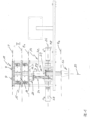
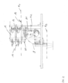
- the Figs. 1 to 3 show a transfer device 10 which, in the case of the present embodiment, is arranged in the product conveying direction between a first conveyor device designed as a horizontal belt conveyor 11 and a conveyor device 12 designed as a filling pipe of a filling device.
- a first conveyor device designed as a horizontal belt conveyor 11
- a conveyor device 12 designed as a filling pipe of a filling device.
- products P are fed to a separating device arranged above the transfer device 10 and designed as a cascade container 13, which are conveyed along two essentially parallel conveyor lines 14, 15 on the conveyor device 11 to the transfer device 10.
- the products P are so-called "salami whips", i.e.
- segmented sausage products which, as shown by way of example in Fig.5 shown, have four salami segments S 1 , S 2 , S 3 and S 4 , each of which is essentially rigid and connected to one another via hinge-like joints G formed from the sausage skin.
- the products P have a substantially straight longitudinal extension due to the production, wherein the products P fall at a falling edge 44 of the conveyor device 11 into an upper container 16 of the cascade container 13, so that the segments S 1 , S 2 , S 3 and S 4 are transferred from the row arrangement formed during the continuous conveying on the conveyor device 11 into a configuration in which the segments S 1 , S 2 , S 3 and S 4 are arranged next to one another in a substantially random manner, such as in Fig.5 shown.
- the containers 16 and the containers 17 are at an increasing angle arranged relative to one another in order to achieve an increasing horizontal distance between the products P before transfer to the transfer device 10.
- the cascade container 13 serves to enable a timed transfer of the products P by the transfer device 10 after the products P in the upper containers 16 have been separated by the lower containers.
- the bottom flaps 18 of the lower containers 17 are opened in accordance with a cycle predetermined by the pivoting conveyor 22 whenever one of the two product holders 23 arranged on the pivoting levers 21 of the pivoting conveyor 22 is located under the respective lower container 17.
- the pivot levers 21 of the pivot conveyor 22 are arranged on a common first pivot axis 26, which is arranged parallel to the conveying plane F and parallel to the receiving plane E 1 and can be pivoted by means of a rotary drive 29 about a second pivot axis 27 arranged orthogonally to the conveying plane F or receiving plane E 1.
- the pivot levers 21 are each driven independently of one another by a rotary drive 28 arranged on the pivot axis 26, such that the product holders 23 can be moved along a pivoting arc B independently of one another between the receiving plane E 1 and a Figs. 1 and 2 shown transfer level E 2 .
- the representation of the transfer device in Fig.1 shows the arrangement of the first conveyor device 11, designed here as a belt conveyor, and the second conveyor device 12, designed here as a filling pipe of a filling device, with crossing conveying directions, whereby in the present case, a horizontal conveying direction towards the transfer device 10 is defined by means of the first conveying device 11 and a conveying direction orthogonal to the first conveying direction 11 is defined by means of the second conveying device 12.
- the first conveying direction 11 has two conveying lines 14, 15 formed next to one another in a common conveying plane F, along which the products P are each conveyed in a row arrangement, wherein the second conveying device 12 formed as a filling tube defines only one conveying line 30 along which conveying takes place after the products P have been transferred from the product receptacles 23 into the filling tube and which is arranged in the middle between the conveying lines 14, 15.
- Fig.4 shows, both for the transfer of the products P from the lower containers 17 of the cascade container 13 in the transfer level E 1 and for the transfer of the products P from the product receptacles 23 into the conveyor device 12 designed as a filling pipe in the transfer level E 2 , a horizontal pivoting of the pivot axis 26 about the orthogonal pivot axis 27 is therefore necessary in order to enable an overlapping arrangement of the containers 17 with the product receptacles 23 in the transfer level E 1 and an overlapping arrangement of the product receptacles 23 with the conveyor device 12 designed here as a filling pipe in the transfer level E 2 .
- the swivel conveyor 22 is shown in a configuration in which the left product holder 23 is arranged in the receiving level E 1 and the right product holder 23 is located in the transfer level E 2.
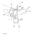
- the product holder 23 is provided with a drive pin 34 at a drive end 33 arranged on the joint axis 26, which is used for the force-locking connection with the Fig.1
- a lever end 35 opposite the drive end 33 is provided with the product holder 23, which is designed as a product bowl with opposing bowl walls 36, 37, which are connected via a pneumatically driven actuator 38, which is arranged on the pivot lever 21, can be pivoted against each other in such a way that a product receiving space 39 formed within the product receptacle 23 can be increased or decreased in its width b, wherein the shell walls 36, 37 are moved past a driver wall 40 forming the rear end of the product receptacle 23.
- the product holder 23 is provided with a tray bottom 41, which is pivoted between a Fig.5 shown lower position and one in Fig.5 is adjustable in the upper position shown by the dash-dotted line, so that in addition to the width b, the height h of the product receiving space 3 can also be changed.
- the swivel conveyor 22 is first swiveled 43 about the orthogonal swivel axis 27, so that the product holder 23 is in a position in the Figs. 1 to 4 shown take-over position II, in which the product holder 23 is covered by the container 17, a door device 45 of the product holder 23 formed by the tray walls 36, 37 is in the open position and the tray base 41 is arranged in its lower position.
- the product holder 23 is thus in the maximum expanded configuration, so that the product P can be taken over after the bottom flap 18 of the container 17 is opened.
- an opposite pivoting 46 takes place about the orthogonal pivot axis 27, such that the product holder 23 and the second conveying device 12 formed by the filling tube are located in a common orthogonal pivot plane E S.
- the tray walls 36, 37 are pivoted against each other to close the door device 45, whereby at the same time or after reaching position III, the tray bottom 41 is adjusted to its upper position (see Fig.5 ) so that the shell bottom 41, which is adjustable by means of the actuator 42, forms a compression device 47 and the Fig.5 the product P presented within the expanded product receiving space 39 is compressed, with the result that the product segments S 1 to S 4 are converted into a more or less parallel and more closely spaced arrangement, thus the product volume is significantly reduced.
- the product holder 23 is now pivoted along a pivoting arc B ( Fig.2 ), during which the product P is accelerated and maintains the compressed configuration due to the centrifugal force acting on the product during the pivoting movement, so that the bowl bottom 41 can be moved back into its lower position in order to enable the product receiving space 39 for a transfer of the product P into the second conveyor device 12 formed by the filling tube after stopping the pivoting movement after reaching the transfer position IV of the product holder 23 in the product transfer plane E 2 .
- the door device 45 Shortly before reaching the transfer position IV of the product holder 23, the door device 45 is opened by pivoting the tray walls 36, 37, so that the product P immediately before being transferred into the filling tube essentially only has physical contact with the product holder 23 via the carrier wall 40 and the kinetic energy impressed on the product P during the pivoting movement in the orthogonal pivoting plane E S in the product holder 23 is essentially unrestricted. is available for discharging the product into the filling tube.
- the right product holder While the left product holder 23 is in the transfer position IV, the right product holder is filled so that during the return movement of the left product holder 23 to the transfer level E 1 , it executes a pivoting movement in the opposite direction to the pivoting movement of the left product holder 23 into the transfer position in the transfer level E 2 .
- a filling device arranged downstream of the second conveyor device 12 can be operated essentially continuously.
Landscapes
- Engineering & Computer Science (AREA)
- Mechanical Engineering (AREA)
- Life Sciences & Earth Sciences (AREA)
- Wood Science & Technology (AREA)
- Zoology (AREA)
- Food Science & Technology (AREA)
- Specific Conveyance Elements (AREA)
- Intermediate Stations On Conveyors (AREA)
Abstract
Die Erfindung betrifft ein Verfahren und eine Vorrichtung zur Übergabe von Produkten P von einer ersten Fördereinrichtung (11) zu einer zweiten Fördereinrichtung (12), wobei die Übergabe mittels eines an einer Schwenkachse (26) schwenkbar gelagerten Schwenkhebel (21) erfolgt, der mit einer Produktaufnahme (23) versehen ist zur Übernahme eines Produkts P von der ersten Fördereinrichtung (11) und Übergabe des Produkts P an die zweite Fördereinrichtung (12) mit Ausführung einer Schwenkbewegung zwischen den Fördereinrichtungen (11, 12), wobei die Produktaufnahme (23) eine Komprimierungseinrichtung zur Verengung eines in der Produktaufnahme (23) ausgebildeten Produktaufnahmeraums aufweist.The invention relates to a method and a device for transferring products P from a first conveyor device (11) to a second conveyor device (12), wherein the transfer takes place by means of a pivoting lever (21) which is pivotably mounted on a pivot axis (26) and is provided with a product holder (23) for taking over a product P from the first conveyor device (11) and transferring the product P to the second conveyor device (12) with execution of a pivoting movement between the conveyor devices (11, 12), wherein the product holder (23) has a compression device for narrowing a product receiving space formed in the product holder (23).
Description
Die Erfindung betrifft ein Verfahren zur Übergabe von Produkten von einer ersten Fördereinrichtung zu einer zweiten Fördereinrichtung, wobei die Fördereinrichtungen einander kreuzende Förderrichtungen aufweisen sowie eine Übergabeeinrichtung zur Übergabe von Produkten von einer ersten Fördereinrichtung zu einer zweiten Fördereinrichtung.The invention relates to a method for transferring products from a first conveyor device to a second conveyor device, wherein the conveyor devices have mutually crossing conveying directions, and to a transfer device for transferring products from a first conveyor device to a second conveyor device.
Verfahren zur Übergabe von Produkten von einer ersten Fördereinrichtung zu einer zweiten Fördereinrichtung kommen insbesondere bei Verpackungsmaschinen zur Anwendung, die nach einer Vereinzelung der in Richtung auf eine Abfülleinrichtung geförderten Produkte eine Richtungsänderung in der Förderung der Produkte notwendig machen, um etwa die Produkte von einer horizontalen Förderrichtung in eine vertikale Förderrichtung zu überführen und eine schwerkraftunterstützte Zuführung der Produkte zu einer Abfülleinrichtung ermöglicht, in der die Produkte mit einer Verpackung versehen werden. Dabei ist die Verpackung regelmäßig an die Form der geförderten Produkte angepasst, was beispielsweise bei Produkten, die eine große Längserstreckung aufweisen dazu führt, dass auch die Verpackung, in die die Produkte in der Abfülleinrichtung abgefüllt werden, eine entsprechend große Längserstreckung aufweist.Methods for transferring products from a first conveyor to a second conveyor are used in particular in packaging machines which, after separating the products conveyed towards a filling device, require a change in the direction of the product conveyance, for example to transfer the products from a horizontal conveying direction to a vertical conveying direction and enable gravity-assisted feeding of the products to a filling device in which the products are provided with packaging. The packaging is usually adapted to the shape of the conveyed products, which, for example in the case of products that have a large longitudinal extension, means that the packaging into which the products are filled in the filling device also has a correspondingly large longitudinal extension.
Selbst bei solchen Produkten, die, wie etwa sogenannte "Salami-Peitschen", eine Segmentierung aufweisen, und die aufgrund der Segmentierung eine Verpackungsmaterial einsparende Verpackung bei einer Stapel- oder Faltkonfiguration der Salami ermöglichen, erfolgt bislang eine derartige Verpackung nur im Falle einer einfachen Segmentierung, also bei zwei durch eine Verbindungsstelle miteinander verbundenen Segmenten, die in Stapelanordnung aufeinanderliegen. Bei Salami-Peitschen, die mehr als zwei Salami-Segmente und somit mehr als eine Verbindungsstelle zwischen den Salami-Segmenten aufweisen, ist es bislang üblich, dass sie in vollständiger Längserstreckung verpackt werden und daher auch ein Verpackungsmaterial in entsprechender Länge benötigt wird.Even in the case of products such as so-called "salami whips" which have a segmentation and which, due to the segmentation, enable packaging that saves packaging material when the salami is stacked or folded, such packaging has so far only been used in the case of simple segmentation, i.e. with two segments connected to one another by a connecting point and lying on top of one another in a stacked arrangement. In the case of salami whips which have more than two salami segments and thus more than one connecting point between the salami segments, it has so far been usual for them to be packaged in their entire length and therefore packaging material of the corresponding length is also required.
Der vorliegenden Erfindung liegt die Aufgabe zugrunde, ein Verfahren sowie eine Vorrichtung vorzuschlagen, dass bzw. die eine beträchtliche Einsparung von Verpackungsmaterial bei der Verpackung von mehrfachsegmentierten Produkten mit großer Längserstreckung, wie beispielsweise eine Salami-Peitsche, ermöglicht.The present invention is based on the object of proposing a method and a device which enables a considerable saving of packaging material when packaging multi-segmented products with a large longitudinal extension, such as a salami whip.
Zur Lösung dieser Aufgabe weist das erfindungsgemäße Verfahren die Merkmale des Anspruchs 1 auf.To achieve this object, the method according to the invention has the features of claim 1.
Erfindungsgemäß erfolgt die Übergabe mittels einer Schwenkbewegung, bei der eine Produktaufnahme zwischen einer Übernahmeposition gegenüber der ersten Fördereinrichtung und einer Übergabeposition gegenüber der zweiten Fördereinrichtung längs eines Schwenkbogens geführt wird, und während der Schwenkbewegung zunächst eine Verengung und nachfolgend eine Aufweitung eines in der Produktaufnahme gebildeten Produktaufnahmeraums erfolgt.According to the invention, the transfer takes place by means of a pivoting movement, in which a product holder is guided along a pivoting arc between a take-over position opposite the first conveyor device and a transfer position opposite the second conveyor device, and during the pivoting movement, a product receiving space formed in the product holder initially narrows and then widens.
Das erfindungsgemäße Verfahren ermöglicht es aufgrund der Produktübergabe mittels einer Schwenkbewegung, dass das Produkt bei hinreichend schneller Förderung des Produkts längs eines Schwenkbogens mit Fliehkraft beaufschlagt wird, sodass eine bei Übergabe des Produkts in die Produktaufnahme gefaltete Anordnung des segmentierten Produkts während der Förderung längs des Schwenkbogens bis in die Übergabeposition aufrecht erhalten bleibt, wobei die gefaltete Produktanordnung durch die Verengung des Produktaufnahmeraums zusätzlich zur Fliehkrafteinwirkung noch weiter komprimiert wird und bei Erreichen der Übergabeposition der Kontakt zwischen der Produktaufnahme und dem Produkt durch die Vergrößerung der Produktaufnahme reduziert wird, um eine möglichst kontaktfreie, die komprimierte Faltkonfiguration des Produkts so wenig wie möglich beeinflussende Übergabe mittels der dem Produkt während der Schwenkbewegung in der Produktaufnahme aufgeprägten kinetischen Energie zu ermöglichen.The method according to the invention enables the product to be subjected to centrifugal force when conveyed sufficiently quickly along a swivel arc due to the product transfer by means of a swivel movement, so that a centrifugal force is generated when the product is transferred into the folded arrangement of the segmented product in the product holder is maintained during conveyance along the pivoting arc up to the transfer position, whereby the folded product arrangement is further compressed by the narrowing of the product holder space in addition to the centrifugal force effect and when the transfer position is reached the contact between the product holder and the product is reduced by enlarging the product holder in order to enable a transfer that is as contact-free as possible and influences the compressed folded configuration of the product as little as possible by means of the kinetic energy impressed on the product during the pivoting movement in the product holder.
Das erfindungsgemäße Verfahren ermöglicht es somit, eine Faltkonfiguration des Produkts, die etwa durch ein Aufstauen des längsgestreckten segmentierten Produkts vor der Übernahme in die Produktaufnahme hergestellt werden kann, während der Übergabe von der ersten Fördereinrichtung an die etwa als Abfüllrohr ausgebildete, zur Abfülleinrichtung führende zweite Fördereinrichtung nicht nur aufrechtzuerhalten, sondern darüber hinaus auch durch die während der Schwenkbewegung erfolgende Verengung des Produktaufnahmeraums der Produktaufnahme weiter zu komprimieren. Aufgrund der die komprimierte Faltkonfiguration möglichst wenig störende Übergabe durch Aufweitung der Produktaufnahme vor der Übergabe des Produkts an die zweite Fördereinrichtung ist es möglich, die komprimierten Faltkonfiguration auch während der Abfüllung des Produkts in die Verpackung aufrechtzuerhalten, sodass für eine Verpackung nur eine entsprechend geringe Menge an Verpackungsmaterial erforderlich ist, verglichen mit der Menge an Verpackungsmaterial, die erforderlich wäre, um das segmentierte Produkt in Längserstreckung aufzunehmen.The method according to the invention thus makes it possible not only to maintain a folded configuration of the product, which can be produced, for example, by accumulating the elongated segmented product before it is transferred to the product holder, during the transfer from the first conveyor to the second conveyor, which is designed, for example, as a filling pipe and leads to the filling device, but also to compress it further by narrowing the product receiving space of the product holder during the pivoting movement. Because the transfer disrupts the compressed folded configuration as little as possible by widening the product holder before the product is transferred to the second conveyor, it is possible to maintain the compressed folded configuration even while the product is being filled into the packaging, so that only a correspondingly small amount of packaging material is required for packaging, compared to the amount of packaging material that would be required to accommodate the segmented product in its longitudinal extension.
Besonders vorteilhaft ist es, wenn der Produktaufnahmeraum ausgehend von einer aufgeweiteten Konfiguration zur Übernahme des Produkts von der ersten Fördereinrichtung zunächst in eine verengte Konfiguration und nachfolgend vor Erreichen der Übergabeposition wieder in die aufgeweitete Konfiguration überführt wird, sodass aufgrund der aufgeweiteten Konfiguration eine möglichst kollisionsfreie Übernahme des Produkts von der Fördereinrichtung in die Produktaufnahme erfolgen kann.It is particularly advantageous if the product receiving space is initially converted from an expanded configuration to a narrowed configuration for receiving the product from the first conveyor device. and is subsequently converted back into the expanded configuration before reaching the transfer position, so that the expanded configuration allows the product to be transferred from the conveyor to the product holder with as little collision as possible.
Wenn die Schwenkbewegung mittels eines Schwenkförderers erfolgt, welcher die Produktaufnahme an einem um eine Schwenkachse verschwenkbaren Schwenkhebel aufweist, kann über die Beschleunigung des Drehantriebs in Abhängigkeit von der Masse des Produkts die gewünschte Fliehkraft eingestellt werden.If the swivel movement is carried out by means of a swivel conveyor which has the product pick-up on a swivel lever which can be swiveled about a swivel axis, the desired centrifugal force can be adjusted by accelerating the rotary drive depending on the mass of the product.
Vorteilhaft ist es auch, wenn in der Übergabeposition eine Übergabe des Produkts aus dem Produktaufnahmeraum in die als Füllrohr einer Abfülleinrichtung ausgebildete zweite Fördereinrichtung erfolgt, derart, dass das Produkt mit der während der Schwenkbewegung in der Produktaufnahme dem Produkt aufgeprägten kinetischen Energie in das Füllrohr gefördert wird, sodass in der durch das Füllrohr gebildeten zweiten Fördereinrichtung eine Förderung des Produkts in die Verpackung mittels kinetischer Energie erfolgt und ein Kontakt des Produkts mit dem Verpackungsboden mit entsprechender Ausnutzung der Länge der Verpackung sichergestellt ist.It is also advantageous if, in the transfer position, the product is transferred from the product receiving space into the second conveying device designed as a filling tube of a filling device, in such a way that the product is conveyed into the filling tube with the kinetic energy impressed on the product during the pivoting movement in the product receiving space, so that in the second conveying device formed by the filling tube, the product is conveyed into the packaging by means of kinetic energy and contact of the product with the packaging base is ensured with appropriate utilization of the length of the packaging.
Wenn bei einer Ausführung der ersten Fördereinrichtung mit zwei nebeneinander in einer gemeinsamen Förderebene angeordneten Förderlinien zur Übergabe der Produkte in ein Füllrohr zwei jeweils einer Förderlinie zugeordnete Produktaufnahmen zwischen einer Übernahmeposition in einer zur Förderebene parallelen Übernahmeebene, in der die Übernahme der Produkte von den Förderlinien in die jeweilige Produktaufnahme erfolgt, abwechselnd jeweils zwischen der Übernahmeposition zur Übernahme eines Produkts von einer Förderlinie und einer Übergabeposition zur Übergabe des Produkts an das Füllrohr verschwenkt werden, derart, dass sich eine Produktaufnahme in der Übernahmeposition befindet, während die andere in der Übergabeposition angeordnet ist, kann die Abfüllleistung der Abfülleinrichtung im Vergleich zu einer Ausführung der ersten Fördereinrichtung mit lediglich einer Förderlinie um das Doppelte gesteigert werden.If, in an embodiment of the first conveyor device with two conveyor lines arranged next to one another in a common conveyor plane for transferring the products into a filling pipe, two product receptacles each assigned to a conveyor line are pivoted between a take-over position in a take-over plane parallel to the conveyor plane, in which the products are taken from the conveyor lines into the respective product receptacle, alternately between the take-over position for taking a product from a conveyor line and a transfer position for transferring the product to the filling pipe, such that one product receptacle is in the take-over position while the other is arranged in the transfer position, the The filling capacity of the filling device can be doubled compared to a design of the first conveyor device with only one conveyor line.
Besonders vorteilhaft ist es, wenn die Schwenkbewegung der Produktaufnahme jeweils aus zwei Schwenkbewegungen zusammengesetzt ist, wobei die eine Schwenkbewegung parallel zur Übernahmeebene und die andere Schwenkbewegung in einer zur Übernahmeebene orthogonal Schwenkebene erfolgt, in der die jeweilige Produktaufnahme und das Füllrohr während der Produktübergabe angeordnet sind, sodass sichergestellt ist, dass dem in der Produktaufnahme angeordneten Produkt in der Phase der Übergabe eine das Produkt in der Produktaufnahme komprimierende Fliehkraft mit überlagerter Schwerkraft aufgeprägt werden kann.It is particularly advantageous if the pivoting movement of the product holder is composed of two pivoting movements, one pivoting movement being parallel to the transfer plane and the other pivoting movement being in a pivoting plane orthogonal to the transfer plane, in which the respective product holder and the filling tube are arranged during the product transfer, so that it is ensured that the product arranged in the product holder can be subjected to a centrifugal force with superimposed gravity compressing the product in the product holder during the transfer phase.
Wenn die von der Produktaufnahme aus der Übernahmeposition in die Übergabeposition ausgeführten Schwenkbewegungen einander nachfolgend und die Zurückführung der Produktaufnahme aus der Übergabeposition in die Übernahmeposition ausgeführten Schwenkbewegungen einander überlagert erfolgen, ist es möglich, die rückführende Bewegung im Vergleich zu der bei der Produktübergabe erfolgenden Bewegung längs einer verkürzten Bewegungsbahn auszuführen.If the swivel movements carried out by the product pick-up from the take-over position to the transfer position occur one after the other and the swivel movements carried out by the return of the product pick-up from the transfer position to the take-over position occur superimposed on one another, it is possible to carry out the return movement along a shortened movement path compared to the movement carried out during the product transfer.
Vorzugsweise erfolgt die Verengung des Produktaufnahmeraums durch Verschließen einer Aufnahmeöffnung der Produktaufnahme mittels einer Türeinrichtung mit nachfolgender Bewegung eines der Aufnahmeöffnung gegenüberliegenden Produktaufnahmebodens in Richtung auf die Türeinrichtung, sodass nach Übernahme des Produkts in die Produktaufnahme eine von zwei einander gegenüberliegenden Seiten der Produktaufnahme ausgeführte räumliche Verengung der Produktaufnahme erfolgt.Preferably, the narrowing of the product receiving space is carried out by closing a receiving opening of the product receiving device by means of a door device with subsequent movement of a product receiving base opposite the receiving opening in the direction of the door device, so that after the product has been taken into the product receiving device, a spatial narrowing of the product receiving device is carried out from two opposite sides of the product receiving device.
Vorzugsweise erfolgt die Aufweitung des Produktaufnahmeraums durch Rückstellung des Produktaufnahmebodens mit nachfolgender Öffnung der Türeinrichtung, sodass der komprimierende Effekt der Fliehkraft auf das Produkt solange wie möglich bis unmittelbar vor Übergabe des Produkts an die zweite Fördereinrichtung aufrechterhalten werden kann.Preferably, the expansion of the product receiving space is carried out by resetting the product receiving floor and subsequently opening the door device so that the compressing effect of the centrifugal force on the product can be maintained as long as possible until immediately before the product is transferred to the second conveyor.
Erfindungsgemäß ist die Übergabeeinrichtung zur Übergabe von Produkten von einer ersten Fördereinrichtung zu einer zweiten Fördereinrichtung als Schwenkförderer ausgebildet mit einem an einer Schwenkachse schwenkbar gelagerten Schwenkhebel, der mit einer Produktaufnahme versehen ist zur Übernahme eines Produkts von der ersten Fördereinrichtung und Übergabe des Produkts an die zweite Fördereinrichtung mittels einer zwischen den Fördereinrichtungen ausgeführten Schwenkbewegung, wobei die Produktaufnahme eine Komprimierungseinrichtung zur Verengung eines in der Produktaufnahme ausgebildeten Produktaufnahmeraums aufweist.According to the invention, the transfer device for transferring products from a first conveyor device to a second conveyor device is designed as a pivoting conveyor with a pivoting lever pivotably mounted on a pivot axis, which is provided with a product holder for taking over a product from the first conveyor device and transferring the product to the second conveyor device by means of a pivoting movement carried out between the conveyor devices, wherein the product holder has a compression device for narrowing a product receiving space formed in the product holder.
Vorzugsweise ist die Produktaufnahme als eine Produktaufnahmeschale ausgebildet mit einer Türeinrichtung zum Verschließen einer an der Produktaufnahmeschale ausgebildeten Aufnahmeöffnung.Preferably, the product holder is designed as a product holder tray with a door device for closing a holder opening formed on the product holder tray.
Wenn die Produktaufnahmeschale zur Ausbildung der Türeinrichtung zwei gegeneinander verschwenkbare Schalenwände aufweist, ist nicht nur eine Komprimierung des in der Produktaufnahme ausgebildeten Aufnahmeraums möglich, sondern die Größe des Schalenaufnahmeraums kann während der Übernahme des Produkts von der ersten Fördereinrichtung einfach an die Größe des Produkts bzw. das Volumen der Produktkonfiguration angepasst werden.If the product receiving tray has two tray walls that can be pivoted against each other to form the door device, not only is it possible to compress the receiving space formed in the product receiving device, but the size of the tray receiving space can also be easily adapted to the size of the product or the volume of the product configuration during the transfer of the product from the first conveyor device.
Wenn zur Ausbildung der Komprimierungseinrichtung ein gegenüber der Aufnahmeöffnung angeordneten Schalenboden zumindest teilweise in Richtung der Aufnahmeöffnung verstellbar ist, wirkt die Komprimierung in Richtung der durch die Schwenkbewegung erzeugten Fliehkraft.If, in order to form the compression device, a shell base arranged opposite the receiving opening is at least partially adjustable in the direction of the receiving opening, the compression acts in the direction of the centrifugal force generated by the pivoting movement.
Vorzugsweise sind bei einer Ausführung der ersten Fördereinrichtung mit zwei nebeneinander in einer gemeinsamen Förderebene angeordneten Förderlinien zur Übergabe der Produkte in eine als Füllrohr einer Abfülleinrichtung ausgebildete zweite Fördereinrichtung zwei Produktaufnahmen am Schwenkförderer ausgebildet, die an jeweils einem auf einer gemeinsamen ersten Schwenkachse angeordneten Schwenkhebel angeordnet sind, wobei die ersten Schwenkachse der Schwenkhebel parallel zur Förderebene angeordnet ist und um eine orthogonal zur Förderebene angeordnete zweite Schwenkachse verschwenkbar ist, sodass eine besonders kompakte Ausgestaltung der Übergabeeinrichtung möglich ist.Preferably, in an embodiment of the first conveyor device with two conveyor lines arranged next to each other in a common conveyor plane for transferring the products into a filling pipe of a filling device formed second conveyor device, two product receptacles are formed on the swivel conveyor, which are each arranged on a swivel lever arranged on a common first swivel axis, wherein the first swivel axis of the swivel lever is arranged parallel to the conveying plane and can be pivoted about a second swivel axis arranged orthogonally to the conveying plane, so that a particularly compact design of the transfer device is possible.
Nachfolgend wird eine bevorzugte Ausführungsform der Erfindung anhand der Zeichnungen näher erläutert.A preferred embodiment of the invention is explained in more detail below with reference to the drawings.
Es zeigen:
- Fig. 1
- Eine im Übergang zwischen einer ersten Fördereinrichtung und einer zweiten Fördereinrichtung angeordnete Übergabeeinrichtung mit zwei Produktaufnahmen in Frontansicht;
- Fig. 2
- die in
Fig. 1 dargestellte Übergabeeinrichtung in seitlicher Ansicht mit Darstellung eines Schwenkförderers mit den an Schwenkhebeln angeordneten Produktaufnahmen; - Fig. 3
- die in den
Fig. 1 und2 dargestellte Übergabeeinrichtung in perspektivischer Ansicht; - Fig. 4
- eine Schnittansicht der in
Fig. 1 dargestellten Übergabeeinrichtung gemäß Schnittlinienverlauf IV-IV; - Fig. 5
- einen mit einer Produktaufnahme versehenen Schwenkhebel des Schwenkförderers in Einzeldarstellung;
- Fig. 6
- eine schematische Darstellung der Schwenkbewegungen einer Produktaufnahme in Draufsicht.
- Fig.1
- A transfer device arranged in the transition between a first conveyor device and a second conveyor device with two product holders in front view;
- Fig.2
- in the
Fig.1 shown transfer device in side view showing a swivel conveyor with the product holders arranged on swivel levers; - Fig.3
- which in the
Fig.1 and2 transfer device shown in perspective view; - Fig.4
- a sectional view of the
Fig.1 shown transfer device according to section line IV-IV; - Fig.5
- a swivel lever of the swivel conveyor provided with a product holder in an individual view;
- Fig.6
- a schematic representation of the swivel movements of a product holder in plan view.
Die
Während der Förderung auf der Fördereinrichtung 11 weisen die Produkte P eine durch die Herstellung bedingte, im Wesentlichen geradlinig ausgebildete Längserstreckung auf, wobei die Produkte P an einer Absturzkante 44 der Fördereinrichtung 11 jeweils in einen oberen Behälter 16 des Kaskadenbehälters 13 stürzen, sodass die Segmente S1, S2, S3 und S4 aus der während der kontinuierlichen Förderung auf der Fördereinrichtung 11 gebildeten Reihenanordnung in eine Konfiguration überführt werden, in der die Segmente S1, S2, S3 und S4 im Wesentlichen regellos nebeneinander angeordnet sind, wie etwa in
Die oberen Behälter 16 des Kaskadenbehälters 13 weisen genauso wie untere Behälter 17 des Kaskadenbehälters 13 eine Bodenklappe 18 mit jeweils zwei, in
Wie aus einer Zusammenschau der
Wenn die Produkte aus den oberen Behältern 16 nach Öffnung der Bodenklappen 18 in die unteren Behälter 17 gelangt sind, befinden sie sich in einer Übernahmeebene E1 oberhalb der Übergabeeinrichtung 10 und können von jeweils einer an einem Schwenkhebel 21 eines Schwenkförderers 22 der Übergabeeinrichtung 10 angeordneten Produktaufnahme 23 übernommen werden. Hierzu erfolgt eine Öffnung der Bodenklappen 18 der unteren Behälter 17 entsprechend einem durch den Schwenkförderer 22 vorgegebenen Takt immer dann, wenn sich eine der beiden an den Schwenkhebeln 21 des Schwenkförderers 22 angeordneten Produktaufnahmen 23 unter dem jeweiligen unteren Behälters 17 befindet.When the products from the
Wie insbesondere aus den
Die Darstellung der Übergabeeinrichtung in
Wie insbesondere
In den
Wie
Wie in
Nachfolgend erfolgt ein entgegengesetztes Verschwenken 46 um die orthogonale Schwenkachse 27, derart, dass sich die Produktaufnahme 23 und die durch das Füllrohr gebildete zweite Fördereinrichtung 12 in einer gemeinsamen orthogonalen Schwenkebene ES befinden.Subsequently, an opposite pivoting 46 takes place about the
Während der Schwenkbewegung der Produktaufnahme 23 in der Übernahmeebene E1 aus der Position II in die Position III werden die Schalenwände 36, 37 zum Schließen der Türeinrichtung 45 gegeneinander verschwenkt, wobei gleichzeitig oder nach Erreichen der Position III eine Verstellung des Schalenbodens 41 in seine obere Position (siehe
Ausgehend von der verengten Konfiguration der Produktaufnahme 39 in der Position III der Produktaufnahme 23 erfolgt nun ein Verschwenken der Produktaufnahme 23 längs eines in der Schwenkebene ES ausgebildeten Schwenkbogens B (
Kurz vor Erreichen der Übergabeposition IV der Produktaufnahme 23 wird die Türeinrichtung 45 durch Aufschwenken der Schalenwände 36, 37 geöffnet, so dass das Produkt P unmittelbar vor Übergabe in das Füllrohr im Wesentlichen nur noch über die Mitnehmerwand 40 Körperkontakt zur Produktaufnahme 23 hat und die dem Produkt P während der Schwenkbewegung in der orthogonalen Schwenkebene ES in der Produktaufnahme 23 aufgeprägte kinetische Energie im Wesentlichen uneingeschränkt für einen Abwurf des Produkts in das Füllrohr zur Verfügung steht.Shortly before reaching the transfer position IV of the
Nach Abwurf bzw. Übergabe des Produkts aus der Produktaufnahme 23 wird diese mit einander überlagerten Schwenkbewegungen um die Schwenkachsen 26 und 27 wieder in die Übernahmeposition II in der Übernahmeebene E1 zurückbewegt.After the product has been dropped or transferred from the
Während sich die linke Produktaufnahme 23 in der Übergabeposition IV befindet, erfolgt eine Befüllung der rechten Produktaufnahme, so dass diese während der Rückbewegung der linken Produktaufnahme 23 in die Übernahmeebene E1 eine zur Schwenkbewegung der linken Produktaufnahme 23 gegensinnige Schwenkbewegung in die Übergabeposition in der Übergabeebene E2 ausführt.While the
Dadurch, dass die linke und rechte Produktaufnahme 23 abwechselnd jeweils zwischen einer Übernahmeposition II zur Übernahme eines Produkts P von einer Förderlinie 14 bzw. 15 und einer Übergabeposition IV zur Übergabe des Produkts P an die von dem Füllrohr gebildete Fördereinrichtung 12 verschwenkt werden, derart, dass sich eine Produktaufnahme 23 in der Übernahmeposition II befindet, während die andere in der Übergabeposition IV angeordnet ist, kann eine der zweiten Fördereinrichtung 12 nachgeordnete Abfülleinrichtung im Wesentlichen kontinuierlich betrieben werden.Because the left and
Claims (14)
dadurch gekennzeichnet,
dass die Übergabe mittels einer Schwenkbewegung erfolgt, bei der eine Produktaufnahme (23) zwischen einer Übernahmeposition II gegenüber der ersten Fördereinrichtung (11) und einer Übergabeposition IV gegenüber der zweiten Fördereinrichtung (12) längs eines Schwenkbogens geführt wird, und während der Schwenkbewegung zunächst eine Verengung und nachfolgend eine Aufweitung eines in der Produktaufnahme (23) gebildeten Produktaufnahmeraums (39) erfolgt.Method for transferring products P from a first conveyor device (11) to a second conveyor device (12), wherein the conveyor devices (11, 12) have mutually crossing conveying directions,
characterized,
that the transfer takes place by means of a pivoting movement in which a product holder (23) is guided along a pivoting arc between a take-over position II opposite the first conveyor device (11) and a transfer position IV opposite the second conveyor device (12), and during the pivoting movement a product receiving space (39) formed in the product holder (23) initially narrows and then widens.
dadurch gekennzeichnet,
dass der Produktaufnahmeraum (39) ausgehend von einer aufgeweiteten Konfiguration zur Übernahme des Produkts P von der ersten Fördereinrichtung (11) zunächst in eine verengte Konfiguration und nachfolgend vor Erreichen der Übergabeposition IV wieder in die aufgeweitete Konfiguration überführt wird.Method according to claim 1,
characterized,
that the product receiving space (39), starting from an expanded configuration for receiving the product P from the first conveyor device (11), is first converted into a narrowed configuration and then back into the expanded configuration before reaching the transfer position IV.
dadurch gekennzeichnet,
dass die Schwenkbewegung mittels eines Schwenkförderers (22) erfolgt, welcher die Produktaufnahme (23) an einem um eine Schwenkachse (26) verschwenkbaren Schwenkhebel (21) aufweist.Method according to claim 1 or 2,
characterized,
that the pivoting movement takes place by means of a pivoting conveyor (22) which has the product holder (23) on a pivoting lever (21) pivotable about a pivot axis (26).
dadurch gekennzeichnet,
dass in der Übergabeposition IV eine Übergabe des Produkts P aus dem Produktaufnahmeraum (39) in die als ein Füllrohr einer Abfülleinrichtung ausgebildete zweite Fördereinrichtung (12) erfolgt, derart, dass das Produkt P mit der während der Schwenkbewegung in der Produktaufnahme (23) dem Produkt P aufgeprägten kinetischen Energie in das Füllrohr gefördert wird.Method according to claim 3,
characterized,
that in the transfer position IV, the product P is transferred from the product receiving space (39) into the second conveying device (12) designed as a filling tube of a filling device, such that the product P is conveyed into the filling tube with the kinetic energy impressed on the product P during the pivoting movement in the product receiving space (23).
dadurch gekennzeichnet,
dass bei einer Ausführung der ersten Fördereinrichtung (11) mit zwei nebeneinander in einer gemeinsamen Förderebene F angeordneten Förderlinien (14, 15) zur Übergabe der Produkte P in ein Füllrohr zwei jeweils einer Förderlinie (14, 15) zugeordnete Produktaufnahmen (23) zwischen einer Übernahmeposition II in einer zur Förderebene F parallelen Übernahmeebene E1, in der die Übernahme der Produkte P von den Förderlinien (14, 15) in die jeweilige Produktaufnahme (23) erfolgt, abwechselnd jeweils zwischen der Übernahmeposition II zur Übernahme eines Produkts P von einer Förderlinie (14, 15) und einer Übergabeposition IV zur Übergabe des Produkts P an das Füllrohr verschwenkt werden, derart, dass sich eine Produktaufnahme (23) in der Übernahmeposition II befindet, während die andere in der Übergabeposition IV angeordnet ist.Method according to claim 4,
characterized,
that in an embodiment of the first conveyor device (11) with two conveyor lines (14, 15) arranged next to one another in a common conveyor plane F for transferring the products P into a filling pipe, two product receptacles (23) each assigned to a conveyor line (14, 15) are pivoted alternately between a take-over position II in a take-over plane E 1 parallel to the conveyor plane F, in which the products P are taken over from the conveyor lines (14, 15) into the respective product receptacle (23), in each case between the take-over position II for taking over a product P from a conveyor line (14, 15) and a transfer position IV for transferring the product P to the filling pipe, such that one product receptacle (23) is in the take-over position II, while the other is arranged in the transfer position IV.
dadurch gekennzeichnet,
dass die Schwenkbewegung der Produktaufnahmen (23) jeweils aus zwei Schwenkbewegungen zusammengesetzt ist, wobei die eine Schwenkbewegung parallel zur Übernahmeebene E1 und die andere Schwenkbewegung in einer zur Übernahmeebene E1 orthogonalen Schwenkebene ES erfolgt, in der die jeweilige Produktaufnahme (23) und das Füllrohr während der Produktübergabe angeordnet sind.Method according to claim 5,
characterized,
that the pivoting movement of the product receptacles (23) is each composed of two pivoting movements, wherein one pivoting movement takes place parallel to the transfer plane E 1 and the other pivoting movement takes place in a pivoting plane E S which is orthogonal to the transfer plane E 1 and in which the respective product receptacle (23) and the filling pipe are arranged during the product transfer.
dadurch gekennzeichnet,
dass die von der Produktaufnahme (23) aus der Übernahmeposition II in die Übergabeposition IV ausgeführten Schwenkbewegungen einander nachfolgend und die zur Rückführung der Produktaufnahme (23) aus der Übergabeposition IV in die Übernahmeposition II ausgeführten Schwenkbewegungen einander überlagert erfolgen.Method according to claim 6,
characterized,
that the pivoting movements carried out by the product holder (23) from the take-over position II to the transfer position IV follow one another and the pivoting movements carried out to return the product holder (23) from the transfer position IV to the take-over position II occur superimposed on one another.
dadurch gekennzeichnet,
dass die Verengung des Produktaufnahmeraums (39) durch Verschließen einer Aufnahmeöffnung der Produktaufnahme (23) mittels einer Türeinrichtung (45) mit nachfolgender Bewegung eines der Aufnahmeöffnung gegenüberliegenden Produktaufnahmebodens in Richtung auf die Türeinrichtung (45) erfolgt.Method according to one of the preceding claims,
characterized,
that the narrowing of the product receiving space (39) takes place by closing a receiving opening of the product receiving device (23) by means of a door device (45) with subsequent movement of a product receiving base opposite the receiving opening in the direction of the door device (45).
dadurch gekennzeichnet,
dass die Aufweitung des Produktaufnahmeraums (39) durch Rückstellung des Produktaufnahmebodens mit nachfolgender Öffnung der Türeinrichtung (45) erfolgt.Method according to one of the preceding claims,
characterized,
that the expansion of the product receiving space (39) takes place by resetting the product receiving floor with subsequent opening of the door device (45).
dadurch gekennzeichnet,
dass die Produktaufnahme (23) als eine Produktaufnahmeschale ausgebildet ist mit einer Türeinrichtung (45) zum Verschließen einer an der Produktaufnahmeschale ausgebildeten Aufnahmeöffnung.Transfer device according to claim 10,
characterized,
that the product holder (23) is designed as a product holder tray with a door device (45) for closing a holder opening formed on the product holder tray.
dadurch gekennzeichnet,
dass die Produktaufnahmeschale zur Ausbildung der Türeinrichtung (45) zwei gegeneinander verschwenkbare Schalenwände (36, 37) aufweist.Transfer device according to claim 11,
characterized,
that the product receiving tray has two tray walls (36, 37) which can be pivoted relative to one another to form the door device (45).
dadurch gekennzeichnet,
dass zur Ausbildung der Komprimierungseinrichtung (47) ein gegenüberliegend der Aufnahmeöffnung angeordneter Schalenboden (41) zumindest teilweise in Richtung der Aufnahmeöffnung verstellbar ist.Transfer device according to claim 10 to 12,
characterized,
in order to form the compression device (47), a shell base (41) arranged opposite the receiving opening is at least partially adjustable in the direction of the receiving opening.
dadurch gekennzeichnet,
dass bei einer Ausführung der ersten Fördereinrichtung (11) mit zwei nebeneinander in einer gemeinsamen Förderebene F angeordneten Förderlinien (14, 15) zur Übergabe der Produkte P in eine als Füllrohr einer Abfülleinrichtung ausgebildete zweite Fördereinrichtungführung (12) zwei Produktaufnahmen (23) am Schwenkförderer (22) ausgebildet sind, die an jeweils einem auf einer gemeinsamen ersten Schwenkachse (26) angeordneten Schwenkhebel (21) angeordnet sind, wobei die erste Schwenkachse (26) der Schwenkhebel (21) parallel zur Förderebene F angeordnet ist und um eine orthogonal zur Förderebene F angeordnete zweite Schwenkachse (27) verschwenkbar ist.Transfer device according to one of claims 10 to 13,
characterized,
that in an embodiment of the first conveyor device (11) with two conveyor lines (14, 15) arranged next to one another in a common conveyor plane F for transferring the products P into a second conveyor device guide (12) designed as a filling pipe of a filling device, two product receptacles (23) are formed on the pivoting conveyor (22), which are each arranged on a pivot lever (21) arranged on a common first pivot axis (26), wherein the first pivot axis (26) of the pivot lever (21) is arranged parallel to the conveyor plane F and can be pivoted about a second pivot axis (27) arranged orthogonal to the conveyor plane F.
Priority Applications (3)
| Application Number | Priority Date | Filing Date | Title |
|---|---|---|---|
| EP22214086.5A EP4385909A1 (en) | 2022-12-16 | 2022-12-16 | Method and transfer device for transferring products from a first conveyor device to a second conveyor device |
| EP25163401.0A EP4545257A2 (en) | 2022-12-16 | 2022-12-16 | Method and transfer device for transferring products from a first conveyor device to a second conveyor device |
| PCT/EP2023/083137 WO2024126015A1 (en) | 2022-12-16 | 2023-11-27 | Method and transfer device for transferring products from a first conveying device to a second conveying device |
Applications Claiming Priority (1)
| Application Number | Priority Date | Filing Date | Title |
|---|---|---|---|
| EP22214086.5A EP4385909A1 (en) | 2022-12-16 | 2022-12-16 | Method and transfer device for transferring products from a first conveyor device to a second conveyor device |
Related Child Applications (1)
| Application Number | Title | Priority Date | Filing Date |
|---|---|---|---|
| EP25163401.0A Division EP4545257A2 (en) | 2022-12-16 | 2022-12-16 | Method and transfer device for transferring products from a first conveyor device to a second conveyor device |
Publications (1)
| Publication Number | Publication Date |
|---|---|
| EP4385909A1 true EP4385909A1 (en) | 2024-06-19 |
Family
ID=84537553
Family Applications (2)
| Application Number | Title | Priority Date | Filing Date |
|---|---|---|---|
| EP22214086.5A Pending EP4385909A1 (en) | 2022-12-16 | 2022-12-16 | Method and transfer device for transferring products from a first conveyor device to a second conveyor device |
| EP25163401.0A Pending EP4545257A2 (en) | 2022-12-16 | 2022-12-16 | Method and transfer device for transferring products from a first conveyor device to a second conveyor device |
Family Applications After (1)
| Application Number | Title | Priority Date | Filing Date |
|---|---|---|---|
| EP25163401.0A Pending EP4545257A2 (en) | 2022-12-16 | 2022-12-16 | Method and transfer device for transferring products from a first conveyor device to a second conveyor device |
Country Status (2)
| Country | Link |
|---|---|
| EP (2) | EP4385909A1 (en) |
| WO (1) | WO2024126015A1 (en) |
Citations (8)
| Publication number | Priority date | Publication date | Assignee | Title |
|---|---|---|---|---|
| US4364467A (en) * | 1980-12-29 | 1982-12-21 | Baker Perkins Holdings Limited | Apparatus for handling biscuits |
| DE3223472A1 (en) * | 1981-07-24 | 1983-02-10 | M.O.S.S. S.r.l., 42029 Reggio Emilia | DEVICE FOR CONVERTING MOLDED OBJECTS FROM A FIRST TO A SECOND BAND CONVEYOR, THEREOF ARE ALIGNED TO THE LATTER |
| US7438192B1 (en) * | 2004-05-28 | 2008-10-21 | Owens-Brockway Glass Container Inc. | Electronic control system for container indexing and inspection apparatus |
| EP1394082B1 (en) * | 2002-09-02 | 2010-04-14 | Ishida Co., Ltd. | Apparatus for transferring and orientating articles, in particular sticks |
| ITBO20090549A1 (en) * | 2009-08-14 | 2011-02-15 | M C Automations S R L | EQUIPMENT FOR THE WRAPPING OF SWEET AND SIMILAR PRODUCTS |
| US7900426B2 (en) * | 2005-11-30 | 2011-03-08 | Sverre Stenbom | Method for packaging food products, and an arrangement for use in such a method |
| EP3254994A1 (en) * | 2016-06-10 | 2017-12-13 | Sidel Participations | A conveying wheel for transporting articles and an apparatus for handling articles including at least one such conveying wheel |
| EP3178742B1 (en) * | 2015-12-08 | 2019-04-17 | Marel A/S | A pick and place gripper device for picking up and re-positioning a deformable food item and a method of doing the same |
-
2022
- 2022-12-16 EP EP22214086.5A patent/EP4385909A1/en active Pending
- 2022-12-16 EP EP25163401.0A patent/EP4545257A2/en active Pending
-
2023
- 2023-11-27 WO PCT/EP2023/083137 patent/WO2024126015A1/en unknown
Patent Citations (8)
| Publication number | Priority date | Publication date | Assignee | Title |
|---|---|---|---|---|
| US4364467A (en) * | 1980-12-29 | 1982-12-21 | Baker Perkins Holdings Limited | Apparatus for handling biscuits |
| DE3223472A1 (en) * | 1981-07-24 | 1983-02-10 | M.O.S.S. S.r.l., 42029 Reggio Emilia | DEVICE FOR CONVERTING MOLDED OBJECTS FROM A FIRST TO A SECOND BAND CONVEYOR, THEREOF ARE ALIGNED TO THE LATTER |
| EP1394082B1 (en) * | 2002-09-02 | 2010-04-14 | Ishida Co., Ltd. | Apparatus for transferring and orientating articles, in particular sticks |
| US7438192B1 (en) * | 2004-05-28 | 2008-10-21 | Owens-Brockway Glass Container Inc. | Electronic control system for container indexing and inspection apparatus |
| US7900426B2 (en) * | 2005-11-30 | 2011-03-08 | Sverre Stenbom | Method for packaging food products, and an arrangement for use in such a method |
| ITBO20090549A1 (en) * | 2009-08-14 | 2011-02-15 | M C Automations S R L | EQUIPMENT FOR THE WRAPPING OF SWEET AND SIMILAR PRODUCTS |
| EP3178742B1 (en) * | 2015-12-08 | 2019-04-17 | Marel A/S | A pick and place gripper device for picking up and re-positioning a deformable food item and a method of doing the same |
| EP3254994A1 (en) * | 2016-06-10 | 2017-12-13 | Sidel Participations | A conveying wheel for transporting articles and an apparatus for handling articles including at least one such conveying wheel |
Also Published As
| Publication number | Publication date |
|---|---|
| EP4545257A2 (en) | 2025-04-30 |
| WO2024126015A1 (en) | 2024-06-20 |
Similar Documents
| Publication | Publication Date | Title |
|---|---|---|
| EP3357816B1 (en) | Method and device for transporting and filling bags | |
| EP3453654B1 (en) | Method and device for grouped arranging and orienting and packaging of individual food products | |
| DE69500340T2 (en) | Device for opening and feeding boxes | |
| EP1955604B1 (en) | Method and device for filling containers with rod-shaped objects | |
| DE1917416A1 (en) | Method and device for transferring objects | |
| DE3786746T2 (en) | APPARATUS FOR TRANSPORTING AND OPENING A BEVERAGE HOLDER. | |
| EP0124740A2 (en) | Device for forming and transporting batches of tobacco | |
| DE2205153A1 (en) | TRANSPORT LINE FOR TRANSPORTING WORK PIECE PACKAGES FOR BAG PRODUCTION | |
| DE60201425T3 (en) | METHOD AND DEVICE FOR CLOSING A BOX BY FOLDING A LATERAL CLOSURE FLAP | |
| WO2005040020A1 (en) | Device for forming piles | |
| EP2108271B9 (en) | Emptying cartridge and method for emptying shaft trays filled with rod-shaped products | |
| EP3197781A2 (en) | Method and device for producing packaging units | |
| EP4385909A1 (en) | Method and transfer device for transferring products from a first conveyor device to a second conveyor device | |
| DE102011107687A1 (en) | Method and device for forming and packaging portions of fibrous material | |
| DE68910438T2 (en) | Method and device for erecting folded tubular blanks. | |
| EP0332160A2 (en) | Coin stacking device | |
| DE102021117317B4 (en) | Device and method for inserting flat objects into a transport container | |
| DE1236921B (en) | Device for removing vertically stacked folding box blanks from a magazine | |
| DE2331166C3 (en) | Device for conveying cigarettes from two storage hoppers to a packaging machine | |
| DE10211785A1 (en) | Method for setting up a letter-sorting machine with a device for conveying scattered items delivers letters as flat stackable items piled up in boxes. | |
| DE102008009803B3 (en) | Apparatus for supplying bags having a spout | |
| EP1712471B1 (en) | Device and method for packaging articles | |
| DE1028418B (en) | Folding and inserting device for lining parts in folding boxes | |
| EP4053024A1 (en) | Method and device for forming packaging stacks | |
| DE202021103617U1 (en) | Device and control unit of a device for feeding flat objects into a transport container |
Legal Events
| Date | Code | Title | Description |
|---|---|---|---|
| PUAI | Public reference made under article 153(3) epc to a published international application that has entered the european phase |
Free format text: ORIGINAL CODE: 0009012 |
|
| STAA | Information on the status of an ep patent application or granted ep patent |
Free format text: STATUS: THE APPLICATION HAS BEEN PUBLISHED |
|
| AK | Designated contracting states |
Kind code of ref document: A1 Designated state(s): AL AT BE BG CH CY CZ DE DK EE ES FI FR GB GR HR HU IE IS IT LI LT LU LV MC ME MK MT NL NO PL PT RO RS SE SI SK SM TR |
|
| STAA | Information on the status of an ep patent application or granted ep patent |
Free format text: STATUS: REQUEST FOR EXAMINATION WAS MADE |
|
| 17P | Request for examination filed |
Effective date: 20241218 |