EP4385902B1 - Hilfsstromsystem - Google Patents
Hilfsstromsystem Download PDFInfo
- Publication number
- EP4385902B1 EP4385902B1 EP22383210.6A EP22383210A EP4385902B1 EP 4385902 B1 EP4385902 B1 EP 4385902B1 EP 22383210 A EP22383210 A EP 22383210A EP 4385902 B1 EP4385902 B1 EP 4385902B1
- Authority
- EP
- European Patent Office
- Prior art keywords
- electric power
- emergency
- normal
- apu
- electric
- Prior art date
- Legal status (The legal status is an assumption and is not a legal conclusion. Google has not performed a legal analysis and makes no representation as to the accuracy of the status listed.)
- Active
Links
Images


Classifications
-
- B—PERFORMING OPERATIONS; TRANSPORTING
- B64—AIRCRAFT; AVIATION; COSMONAUTICS
- B64D—EQUIPMENT FOR FITTING IN OR TO AIRCRAFT; FLIGHT SUITS; PARACHUTES; ARRANGEMENT OR MOUNTING OF POWER PLANTS OR PROPULSION TRANSMISSIONS IN AIRCRAFT
- B64D41/00—Power installations for auxiliary purposes
-
- B—PERFORMING OPERATIONS; TRANSPORTING
- B60—VEHICLES IN GENERAL
- B60L—PROPULSION OF ELECTRICALLY-PROPELLED VEHICLES; SUPPLYING ELECTRIC POWER FOR AUXILIARY EQUIPMENT OF ELECTRICALLY-PROPELLED VEHICLES; ELECTRODYNAMIC BRAKE SYSTEMS FOR VEHICLES IN GENERAL; MAGNETIC SUSPENSION OR LEVITATION FOR VEHICLES; MONITORING OPERATING VARIABLES OF ELECTRICALLY-PROPELLED VEHICLES; ELECTRIC SAFETY DEVICES FOR ELECTRICALLY-PROPELLED VEHICLES
- B60L3/00—Electric devices on electrically-propelled vehicles for safety purposes; Monitoring operating variables, e.g. speed, deceleration or energy consumption
- B60L3/0092—Electric devices on electrically-propelled vehicles for safety purposes; Monitoring operating variables, e.g. speed, deceleration or energy consumption with use of redundant elements for safety purposes
-
- B—PERFORMING OPERATIONS; TRANSPORTING
- B60—VEHICLES IN GENERAL
- B60L—PROPULSION OF ELECTRICALLY-PROPELLED VEHICLES; SUPPLYING ELECTRIC POWER FOR AUXILIARY EQUIPMENT OF ELECTRICALLY-PROPELLED VEHICLES; ELECTRODYNAMIC BRAKE SYSTEMS FOR VEHICLES IN GENERAL; MAGNETIC SUSPENSION OR LEVITATION FOR VEHICLES; MONITORING OPERATING VARIABLES OF ELECTRICALLY-PROPELLED VEHICLES; ELECTRIC SAFETY DEVICES FOR ELECTRICALLY-PROPELLED VEHICLES
- B60L50/00—Electric propulsion with power supplied within the vehicle
-
- B—PERFORMING OPERATIONS; TRANSPORTING
- B64—AIRCRAFT; AVIATION; COSMONAUTICS
- B64D—EQUIPMENT FOR FITTING IN OR TO AIRCRAFT; FLIGHT SUITS; PARACHUTES; ARRANGEMENT OR MOUNTING OF POWER PLANTS OR PROPULSION TRANSMISSIONS IN AIRCRAFT
- B64D27/00—Arrangement or mounting of power plants in aircraft; Aircraft characterised by the type or position of power plants
- B64D27/02—Aircraft characterised by the type or position of power plants
- B64D27/10—Aircraft characterised by the type or position of power plants of gas-turbine type
-
- B—PERFORMING OPERATIONS; TRANSPORTING
- B64—AIRCRAFT; AVIATION; COSMONAUTICS
- B64D—EQUIPMENT FOR FITTING IN OR TO AIRCRAFT; FLIGHT SUITS; PARACHUTES; ARRANGEMENT OR MOUNTING OF POWER PLANTS OR PROPULSION TRANSMISSIONS IN AIRCRAFT
- B64D31/00—Power plant control systems; Arrangement of power plant control systems in aircraft
- B64D31/02—Initiating means
-
- F—MECHANICAL ENGINEERING; LIGHTING; HEATING; WEAPONS; BLASTING
- F02—COMBUSTION ENGINES; HOT-GAS OR COMBUSTION-PRODUCT ENGINE PLANTS
- F02C—GAS-TURBINE PLANTS; AIR INTAKES FOR JET-PROPULSION PLANTS; CONTROLLING FUEL SUPPLY IN AIR-BREATHING JET-PROPULSION PLANTS
- F02C7/00—Features, components parts, details or accessories, not provided for in, or of interest apart form groups F02C1/00 - F02C6/00; Air intakes for jet-propulsion plants
- F02C7/26—Starting; Ignition
-
- H—ELECTRICITY
- H02—GENERATION; CONVERSION OR DISTRIBUTION OF ELECTRIC POWER
- H02J—ELECTRIC POWER NETWORKS; CIRCUIT ARRANGEMENTS OR SYSTEMS FOR SUPPLYING OR DISTRIBUTING ELECTRIC POWER; SYSTEMS FOR STORING ELECTRIC ENERGY
- H02J1/00—Circuit arrangements for DC mains or DC distribution networks
- H02J1/10—Parallel operation of DC sources
- H02J1/12—Parallel operation of DC sources having power converters with further DC sources without power converters
-
- H—ELECTRICITY
- H02—GENERATION; CONVERSION OR DISTRIBUTION OF ELECTRIC POWER
- H02J—ELECTRIC POWER NETWORKS; CIRCUIT ARRANGEMENTS OR SYSTEMS FOR SUPPLYING OR DISTRIBUTING ELECTRIC POWER; SYSTEMS FOR STORING ELECTRIC ENERGY
- H02J3/00—Circuit arrangements for AC mains or AC distribution networks
- H02J3/007—Arrangements for selectively connecting one or more loads to one or more power sources or power lines
- H02J3/0073—Arrangements for selectively connecting one or more loads to one or more power sources or power lines by providing alternative feeding paths when the main path fails
-
- H—ELECTRICITY
- H02—GENERATION; CONVERSION OR DISTRIBUTION OF ELECTRIC POWER
- H02J—ELECTRIC POWER NETWORKS; CIRCUIT ARRANGEMENTS OR SYSTEMS FOR SUPPLYING OR DISTRIBUTING ELECTRIC POWER; SYSTEMS FOR STORING ELECTRIC ENERGY
- H02J9/00—Circuit arrangements for emergency or stand-by power supply, e.g. for emergency lighting
- H02J9/002—Circuit arrangements for emergency or stand-by power supply, e.g. for emergency lighting in which a reserve is maintained in an energy source by disconnecting non-critical loads, e.g. maintaining a reserve of charge in a vehicle battery for starting an engine
-
- B—PERFORMING OPERATIONS; TRANSPORTING
- B60—VEHICLES IN GENERAL
- B60L—PROPULSION OF ELECTRICALLY-PROPELLED VEHICLES; SUPPLYING ELECTRIC POWER FOR AUXILIARY EQUIPMENT OF ELECTRICALLY-PROPELLED VEHICLES; ELECTRODYNAMIC BRAKE SYSTEMS FOR VEHICLES IN GENERAL; MAGNETIC SUSPENSION OR LEVITATION FOR VEHICLES; MONITORING OPERATING VARIABLES OF ELECTRICALLY-PROPELLED VEHICLES; ELECTRIC SAFETY DEVICES FOR ELECTRICALLY-PROPELLED VEHICLES
- B60L2200/00—Type of vehicles
- B60L2200/10—Air crafts
-
- B—PERFORMING OPERATIONS; TRANSPORTING
- B64—AIRCRAFT; AVIATION; COSMONAUTICS
- B64D—EQUIPMENT FOR FITTING IN OR TO AIRCRAFT; FLIGHT SUITS; PARACHUTES; ARRANGEMENT OR MOUNTING OF POWER PLANTS OR PROPULSION TRANSMISSIONS IN AIRCRAFT
- B64D41/00—Power installations for auxiliary purposes
- B64D2041/002—Mounting arrangements for auxiliary power units (APU's)
-
- B—PERFORMING OPERATIONS; TRANSPORTING
- B64—AIRCRAFT; AVIATION; COSMONAUTICS
- B64D—EQUIPMENT FOR FITTING IN OR TO AIRCRAFT; FLIGHT SUITS; PARACHUTES; ARRANGEMENT OR MOUNTING OF POWER PLANTS OR PROPULSION TRANSMISSIONS IN AIRCRAFT
- B64D2221/00—Electric power distribution systems onboard aircraft
-
- F—MECHANICAL ENGINEERING; LIGHTING; HEATING; WEAPONS; BLASTING
- F05—INDEXING SCHEMES RELATING TO ENGINES OR PUMPS IN VARIOUS SUBCLASSES OF CLASSES F01-F04
- F05D—INDEXING SCHEME FOR ASPECTS RELATING TO NON-POSITIVE-DISPLACEMENT MACHINES OR ENGINES, GAS-TURBINES OR JET-PROPULSION PLANTS
- F05D2220/00—Application
- F05D2220/70—Application in combination with
- F05D2220/76—Application in combination with an electrical generator
-
- F—MECHANICAL ENGINEERING; LIGHTING; HEATING; WEAPONS; BLASTING
- F05—INDEXING SCHEMES RELATING TO ENGINES OR PUMPS IN VARIOUS SUBCLASSES OF CLASSES F01-F04
- F05D—INDEXING SCHEME FOR ASPECTS RELATING TO NON-POSITIVE-DISPLACEMENT MACHINES OR ENGINES, GAS-TURBINES OR JET-PROPULSION PLANTS
- F05D2260/00—Function
- F05D2260/85—Starting
-
- H—ELECTRICITY
- H02—GENERATION; CONVERSION OR DISTRIBUTION OF ELECTRIC POWER
- H02J—ELECTRIC POWER NETWORKS; CIRCUIT ARRANGEMENTS OR SYSTEMS FOR SUPPLYING OR DISTRIBUTING ELECTRIC POWER; SYSTEMS FOR STORING ELECTRIC ENERGY
- H02J2105/00—Networks for supplying or distributing electric power characterised by their spatial reach or by the load
- H02J2105/30—Networks for supplying or distributing electric power characterised by their spatial reach or by the load the load networks being external to vehicles, i.e. exchanging power with vehicles
- H02J2105/32—Networks for supplying or distributing electric power characterised by their spatial reach or by the load the load networks being external to vehicles, i.e. exchanging power with vehicles for aircrafts
Definitions
- the present invention relates to auxiliary power generator systems for an aircraft. More particular, the present invention relates to an auxiliary power system with a new architecture that includes an essential auxiliary power unit (APU) with dual and fully redundant starter and electrical power generation systems that can connect independently to a normal electric busbar network or an emergency electric busbar network of an aircraft. In addition, the present invention also relates to an aircraft comprising said redundant auxiliary power system and a method for supplying electric power to an aircraft by means of said system, according to the operating modes of the redundant auxiliary power system, either normal or emergency.
- APU essential auxiliary power unit
- An Auxiliary Power Unit is a gas turbine engine which is used in aircraft to provide electrical and/or pneumatic power to various systems and components in the aircraft as an auxiliary or secondary source of power.
- the APU is generally located in the aircraft fuselage at/or near the tail cone section.
- the APU allows the aircraft to be autonomous of the external electrical and pneumatic power sources on the ground and in-flight.
- a typical gas turbine APU for aircraft comprises three main sections: power section, load compressor section and gearbox section.
- the power section is the gas-generator portion of the engine and produces all the shaft power for the APU.
- the load compressor section is generally a shaft mounted compressor that provides pneumatic power for the aircraft through some APUs extract bleed air from the power section compressor.
- the gearbox transfers power from the main shaft of the engine to an oil-cooled generator for electrical power.
- the APUs can be used to provide power to an aircraft when the primary engines are not running, for example, while the aircraft is on ground.
- the APUs can also provide temporary power to start the primary engines during normal operations, and/or temporary emergency power during an engine-out condition or other emergency situations, and/or continuous emergency power until aircraft landing.
- the APUs can be used to replace one main generator failed for dispatch conditions.
- the aircraft typically includes a RAT that is usually connected to an electrical generator to be used as an emergency power source.
- the RAT will power some aircraft systems.
- the RAT is stowed into the fuselage or wing in normal conditions and is deployed automatically following complete loss of power.
- APU and RAT are completely separated systems located at separate parts of the aircraft. While APU provides auxiliary power, the RAT is used as source of emergency power. Both systems generate electrical power through respective electrical power generators.
- there are also some aircraft architectures where the APU is used as an emergency power source and this is possible due to a legacy overall aircraft architecture (non-fly-by-wire) and requirements demonstrated to have enough compliance with this.
- ETOPS flight Extended Operations flight
- this aircraft architecture requires the APU to be running in the ETOPS sector.
- EP 2 228 881 A2 discloses a redundant auxiliary power system for an aircraft, comprising:
- a redundant auxiliary power system for an aircraft, this system including a dual and fully redundant starter and electrical power generation systems that can connect independently to the normal or emergency electric busbar network of the aircraft.
- the proposed redundant auxiliary power system supplies electrical and pneumatic power for ground operations and degraded/MMEL (master minimum equipment list) flight operations; and further supplied emergency power in case of LMES (loss of main electrical supply)/TEFO (total engine flame out) and replaces RAT functionality.
- the present invention provides an auxiliary power unit according to claim 1, an aircraft according to claim 9 and methods for supplying electric power to an aircraft according to claims 10 and 11.
- Dependent claims disclose particular embodiments of the present invention.
- a first aspect of the invention provides a redundant auxiliary power system for an aircraft, comprising:
- the present auxiliary power system comprises an APU that provides standard APU functions which are deliver electrical and pneumatic power for ground operations and degraded/MMEL flight operations for an aircraft. Particularly, it has been specified that this APU supplies electric power in an operative mode.
- operative mode of APU is understood as the mode when the APU is working, i.e., has been started up.
- This redundant auxiliary power system is suitable to be installed in an aircraft and to be connected electrically to the aircraft electric busbar networks.
- the aircraft electric busbar networks comprise at least a normal electric busbar network and an emergency electric busbar network, wherein both normal and emergency electric busbar networks are composed by an AC (alternating current) and/or a DC (direct current).
- the electric busbar networks referred for the redundant auxiliary power system are the electric busbar networks of an aircraft.
- the normal electric power generator is further configured to supply electric power to the emergency electric busbar network
- the APU controller is further configured to activate the normal electric power generator for supplying electric power to either the normal or the emergency electric busbar network according to the normal mode of the redundant auxiliary power system, based on data received from the electrical power controller, data related to the aircraft operational parameters, or a manually activated signal.
- the APU controller is configured to be powered supplied by the emergency electric busbar network in any case to remain independent and segregated from the normal electric busbar network.
- the electrical power controller is further configured to monitor the operation of the starting means, such that upon a malfunction in one of the starting means, the APU controller is configured to deactivate the activated starting means and activate the other starting means to start up the APU. This advantageously would never lead to a NOGO decision as a result of a failure of one starting means.
- the electrical power controller is further configured to monitor the operation of the electric power generators, such that upon a malfunction in one of the electric power generators, the APU controller is configured to deactivate the activated electric power generator and activate the other electric power generator for electric power supply.
- the electrical power controller is able to detect it, report it to the centralized maintenance system and Flight Warning System, and then the system will be reconfigured accordingly (manually or automatically by means of the APU controller).
- the monitoring performed by the electric power controller advantageously allows the present system to reconfigure itself automatically and autonomously and guarantees the availability of the starting and generating functions for the emergency electric network.
- the auxiliary power system is configured to operate according to
- the emergency mode is understood as the operating mode that is instructed to the APU controller when TEFO or LMES occurs.
- the normal mode is understood as the operating mode when there are no emergency mode instructions.
- the aircraft operational parameters are ...
- the redundant auxiliary power system comprises a starter power unit for each starting means, these starter power units being power supplied by the emergency electric busbar network.
- These starter power units are a power converters in charge of converting low voltage DC to high voltage DC. The use of the starter power units would be necessary in case a high voltage battery (HVDC BATT) would not be available or certifiable to supply an emergency electric power.
- HVDC BATT high voltage battery
- any starting means could perform a normal or an emergency start-up, thus, the choice between them depends on the aircraft operation (normal mode or emergency mode), and the difference between the normal and emergency start up is basically a faster and more powerful start up for emergency mode.
- the present invention provides an aircraft comprising a redundant auxiliary power system according to the first inventive aspect.
- the redundant auxiliary power system is arranged at the rear end or tail cone of the aircraft.
- the APU controller activates the emergency starting means to start up the APU, and once the APU has been started up, then the APU controller activates the emergency electric power generator for supplying electric power to the emergency electric busbar network.
- the present invention provides a method for supplying electric power to an aircraft by means of a redundant auxiliary power system according to the first inventive aspect, wherein if the redundant auxiliary power system is operated according to a normal mode, the method comprises:
- the present method provides the advantage to supply electric power to an aircraft networks irrespective of the operation mode (normal or emergency) and regardless of whether any starting means fails.
- the method further comprises deciding whether the normal electric power generator supplies electric power to the normal or emergency electric busbar network in the aircraft. This is possible thanks to the particular configuration wherein the normal electric power generator can be connected to the normal or emergency electric busbar network to supply electric power to any of them.
- the method further comprises deciding whether the emergency electric power generator supplies electric power to the normal or emergency electric busbar network in the aircraft. This is possible thanks to the particular configuration wherein the emergency electric power generator can be connected to the normal or emergency electric busbar network to supply electric power to any of them.
- the method comprises activating both electric power generators so that one of the electric busbar network is power supplied by one of the generator and the other electric busbar network is power supplied by the other generator.
- the two electric power generators are connected to the electric busbar networks at the same time.
- the present invention discloses according to figures 1-4 a redundant auxiliary power system for supplying electric power to aircraft electric busbar networks (2, 3) according to an operating mode, normal mode or emergency mode.
- the emergency mode is understood as the operating mode of the redundant auxiliary power system when receive instructions related to Total Engine Flame Out “TEFO” or Loss of Main Electrical Supply “LMES”; and the normal mode is understood as the preset operating mode whenever there are no instructions to operate according to the emergency mode. Therefore, a normal mode will be operated when there is no emergency mode instructions.
- the system comprises an APU (10) for supplying power in an operative mode.
- the system also comprises a normal (2) and an emergency (3) electric busbar networks that corresponds to the electric busbar networks of an aircraft (1). That is, the present system is connected to the electric busbar networks of the aircraft when boarding and settling into the aircraft (1).
- the system also comprises two starting means, a normal (4) and an emergency (5) starting means, to independently start up the APU (10) as necessary; and two electric power generators, a normal (6) and emergency (7) electric power generators to generate electric power when the APU (10) is in the operative mode.
- the normal (4) and emergency (5) starting means are both configured to start up the APU (10) for independently operating at least one of the normal (6) and emergency (7) electric power generator. In these embodiments, the
- FIG. 1 shows a first embodiment of the redundant auxiliary power system wherein the normal (6) electric power generator is provided to supply electric power to the normal (2) electric busbar network whilst the emergency (7) electric power generator is provided to supply electric power to the emergency (3) electric busbar network. Therefore, each electric power generator (6, 7) is intended to be connected to a particular electric busbar network (2, 3).
- the configuration of this first embodiment provides a fully redundancy for APU startup. This embodiment is provided when certification risks have been identified and the redundant auxiliary power system provides fully redundancy of the starter function only, with the normal (6) electric power generator dedicated to the normal (2) electric busbar network and the emergency (7) electric power generator dedicated to the emergency (3) electric busbar network.
- the redundant auxiliary power system shown in said figures 1-4 further comprises an electrical power controller (8) that controls the electrical operational parameters of both normal (2) and emergency (3) electric busbar networks. Moreover, the electrical power controller (8) is also configured to monitor the operating time of each electric power generator (6, 7), and to monitor the operation of both starting means (4, 5) and electric power generators (6, 7) with the aim to detect a malfunction in any of them.
- the system comprises an APU controller (9) in data communication with the electrical power controller (8) and being configured to control the operative mode of the APU (10) according to data received from the electrical power controller (8), data related to the aircraft operational parameters or a manually activated signal. That is, the APU controller (9) operated the APU (10) based on normal or emergency mode that may be instructed from the electrical power controller (8) or a manually activated signal or may be determined from received data related to aircraft operational parameters.
- the redundant auxiliary power system is able to reconfigure itself automatically and autonomously thanks to the electrical power controller (8) that confirms the expected configuration with the APU controller (9), or manually with specific crew action, to ensure the availability of a starting means and electric power generator for the normal (2) or emergency (3) electric busbar network.
- the APU controller (9) is an engine control box as a full-authority digital electronic controller in charge of the APU logic for all modes of the APU operations, and control of the automatic shutdown, among others.
- the engine control box controls the normal (4) and emergency (5) starting means, and the starting means (4, 5) engages if an air intake (also provided in the system) is fully open and the starting means (4, 5) is in starting condition.
- This engine control box remains supplied on the emergency electric busbar network independent and segregated from the normal electric busbar network to ensure the start-up of the APU (10).
- This engine control box will always be able to decide the configuration to be applied depending on the health status of the redundant auxiliary power system and the electric busbar networks.
- the engine control box is in charge of computing if an emergency or normal start up is required depending on the needs.
- the redundant auxiliary power system is configured to operate according to an emergency mode or a normal mode.
- the APU controller (9) is configured to activate the emergency (5) starting means to start up the APU (10) and the emergency (7) electric power generator for supplying electric power to the emergency (3) electric.
- the operation of the APU controller varies between figures 1-4 .
- the APU controller (9) is configured to activate one of the normal (4) or emergency (5) starting means to start up the APU (10) and one of the normal (6) or emergency (7) electric power generators for supplying electric power to the corresponding normal (2) or emergency (3) electric busbar network.
- the normal (6) electric power generator would be activated by the APU controller (9), as well as if it is necessary to supply power to the emergency (3) electric busbar network the emergency (7) electric power generator would be activated by the APU controller (9).
- the APU controller (9) is configured to activate one of the normal (4) or emergency (5) starting means to start up the APU (10) and one of the normal (6) or emergency (7) electric power generators for supplying electric power to the emergency (3) electric busbar network or the normal (6) electric power generator for supplying electric power to the normal (2) electric busbar network.
- the normal (6) electric power generator would be activated by the APU controller (9).
- the emergency (3) electric busbar network any one of the normal (6) and emergency (7) electric power generators would be activated by the APU controller (9).
- the electrical power controller (8) In the process of supplying power to the emergency (3) electric busbar network in normal mode, if the normal (6) electric power generator has been activated and the electrical power controller (8) detects a malfunction in this normal (6) electric power generator, the electrical power controller (8) notifies of this to the APU controller (9) for the APU controller (9) to deactivate the normal (6) electric power generator and activate the emergency (7) electric power generator for supplying power to the emergency (3) electric busbar network.
- the emergency (7) electric power generator activated so that in case of failure, the normal (6) electric power generator will be then activated for supplying power to the emergency (3) electric busbar network.
- the APU controller (9) is configured to activate one of the normal (4) or emergency (5) starting means to start up the APU (10) and one of the normal (6) or emergency (7) electric power generators for supplying electric power to the normal (2) electric busbar network or the emergency (7) electric power generator for supplying electric power to the emergency (3) electric busbar network.
- the emergency (7) electric power generator would be activated by the APU controller (9).
- any one of the normal (6) and emergency (7) electric power generators would be activated by the APU controller (9).
- the APU controller (9) is configured to activate one of the normal (4) or emergency (5) starting means to start up the APU (10) and one of the normal (6) or emergency (7) electric power generators for supplying electric power to any one of the normal (2) or emergency (3) electric busbar network.
- the APU controller (9) any one of the two electric power generators (6, 7) would be activated by the APU controller (9).
- any one of the normal (2) electric busbar network also any one of the normal (6) and emergency (7) electric power generators would be activated by the APU controller (9).
- the electrical power controller (8) detects a malfunction in this normal (6) electric power generator, the electrical power controller (8) notifies of this to the APU controller (9) for the APU controller (9) to deactivate the normal (6) electric power generator and activate the emergency (7) electric power generator for supplying power to the emergency (3) electric busbar network.
- the emergency (7) electric power generator activated, so that in case of failure, the normal (6) electric power generator will be then activated for supplying power to the emergency (3) electric busbar network.
- the APU controller (9) is configured to selectively actuate the starting means (4, 5) and the electric power generators (6, 7) according to the operating mode (normal or emergency).
- the APU controller (8) take into account data received from the electrical power controller (8) for example informing about a failure in any starting means (4, 5) or electric power generator (6, 7) for reconfiguring the operation of the system.
- the APU controller (9) may receive aircraft operational parameters which can condition a particular operation of the system such as informing about the need to supply electric power to a specific electric busbar network (2, 3), so that the APU controller (9) reconfigures accordingly.
- the APU controller (9) may be also instructed by a manually activated signal to operate according to this specific operating mode i.e. the need to supply electric power to a specific electric busbar network.
- the method comprises the following steps:
- the present redundant auxiliary power system is configured to operate in normal mode by default unless it is notified to operate according to emergency mode.
- the activation of one of the starting means (4, 5) is indiscriminate while the activation of one electric power generator (6, 7) will depend on the electric busbar network (2, 3) to be supplied.
- the APU controller (9) may activate any one of the electric power generators (6, 7) for supplying electric power to the emergency (3) electric busbar network.
- the APU controller (9) activates the normal (6) electric power generator since it is the only one intended to supply electric power to the normal (2) electric busbar network according to the normal mode.
- the APU controller (9) may activate any one of the electric power generators (6, 7) for supplying electric power to the normal (2) electric busbar network.
- the APU controller (9) activates the emergency (7) electric power generator since it is the only one intended to supply electric power to the emergency (3) electric busbar network according to the normal mode.
- the APU controller (9) may activate any one of the electric power generators (6, 7) for supplying electric power to the normal (2) electric busbar network.
- the APU controller (9) may activate any one of the electric power generators (6, 7) for supplying electric power to the emergency (3) electric busbar network.
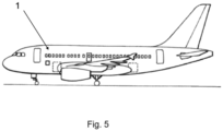
- Figure 5 shows an aircraft (1) comprising a redundant auxiliary power system according to any one of the embodiments disclosed above.
Landscapes
- Engineering & Computer Science (AREA)
- Power Engineering (AREA)
- Aviation & Aerospace Engineering (AREA)
- Mechanical Engineering (AREA)
- Transportation (AREA)
- Chemical & Material Sciences (AREA)
- Combustion & Propulsion (AREA)
- Life Sciences & Earth Sciences (AREA)
- Sustainable Development (AREA)
- Sustainable Energy (AREA)
- General Engineering & Computer Science (AREA)
- Business, Economics & Management (AREA)
- Emergency Management (AREA)
- Stand-By Power Supply Arrangements (AREA)
- Supply And Distribution Of Alternating Current (AREA)
Claims (15)
- Redundantes Hilfsenergiesystem für ein Flugzeug (1), umfassend:- ein Hilfstriebwerk "APU" (10) zum Liefern von Energie in einem operativen Modus;- ein elektrisches Sammelschienennetzwerk für den Normalfall (2) und den Notfall (3);- ein Startmittel für den Normalfall (4) und den Notfall (5), wobei beide Startmittel (4, 5) dazu ausgelegt sind, das APU (10) unabhängig zu starten;- einen elektrischen Energiegenerator für den Normalfall (6) und den Notfall (7), wobei beide elektrischen Energiegeneratoren (6, 7) dazu ausgelegt sind, elektrische Energie zu erzeugen, wenn sich das APU (10) im operativen Modus befindet; wobei der elektrische Energiegenerator für den Normalfall (6) dazu ausgelegt ist, elektrische Energie an das elektrische Sammelschienennetzwerk für den Normalfall (2) zu liefern, und der elektrische Energiegenerator für den Notfall (7) dazu ausgelegt ist, elektrische Energie an das elektrische Sammelschienennetzwerk für den Notfall (3) zu liefern,- eine elektrische Energiesteuerung (8), die dazu ausgelegt ist, die elektrischen Betriebsparameter des elektrischen Sammelschienennetzwerks für den Normalfall (2) und einen Notfall (3) zu steuern; und- eine APU-Steuerung (9), die mit der elektrischen Energiesteuerung (8) verbunden ist und dazu ausgelegt ist, den operativen Modus des APU (10) basierend auf Daten, die von der elektrischen Energiesteuerung (8) empfangen werden, Daten bezüglich der Betriebsparameter des Flugzeugs oder einem manuell aktivierten Signal zu steuern;wobeisowohl das Startmittel für den Normalfall (4) als auch den Notfall (5) dazu ausgelegt sind, das APU (10) zu starten, um unabhängig mindestens einen des elektrischen Energiegenerators für den Normalfall (6) und den Notfall (7) zu betreiben;und wobei das redundante Hilfsenergiesystem dazu ausgelegt ist, gemäß Folgendem zu arbeiten:- ein Notfallmodus, bei dem die APU-Steuerung (9) dazu ausgelegt ist, Folgendes zu aktivieren:o das Startmittel für den Notfall (5), um das APU (10) zu starten, undo den elektrischen Energiegenerator für den Notfall (7), um elektrische Energie an das elektrische Sammelschienennetzwerk für den Notfall (3) zu liefern; oder- ein Normalmodus, bei dem die APU-Steuerung (9) dazu ausgelegt ist, Folgendes zu aktivieren:o eines des Startmittels für den Normalfall (4) oder den Notfall (5), um das APU (10) zu starten, undo einen des elektrischen Energiegenerators für den Normalfall (6) oder den Notfall (7), um elektrische Energie an das elektrische Sammelschienennetzwerk für den Normalfall (2) bzw. den Notfall (3) zu liefern.
- Redundantes Hilfsenergiesystem nach dem vorherigen Anspruch, wobei der elektrische Energiegenerator für den Normalfall (6) ferner dazu ausgelegt ist, elektrische Energie an das elektrische Sammelschienennetzwerk für den Notfall (3) zu liefern, und wobei die APU-Steuerung (9) ferner dazu ausgelegt ist, den elektrischen Energiegenerator für den Normalfall (6) zu aktivieren, um elektrische Energie an entweder das elektrische Sammelschienennetzwerk für den Normalfall (2) oder den Notfall (3) zu liefern, gemäß dem Normalmodus des redundanten Hilfsenergiesystems, basierend auf Daten, die von der elektrischen Energiesteuerung (8) empfangen werden, Daten bezüglich der Betriebsparameter des Flugzeugs oder einem manuell aktivierten Signal.
- Redundantes Hilfsenergiesystem nach einem der vorherigen Ansprüche, wobei der elektrische Energiegenerator für den Notfall (7) ferner dazu ausgelegt ist, elektrische Energie an das elektrische Sammelschienennetzwerk für den Normalfall (2) zu liefern, und wobei die APU-Steuerung (9) ferner dazu ausgelegt ist, den elektrischen Energiegenerator für den Notfall (7) zu aktivieren, um elektrische Energie an entweder das elektrische Sammelschienennetzwerk für den Normalfall (2) oder den Notfall (3) zu liefern, gemäß dem Normalmodus des redundanten Hilfsenergiesystems, basierend auf Daten, die von der elektrischen Energiesteuerung (8) empfangen werden, Daten bezüglich der Betriebsparameter des Flugzeugs oder einem manuell aktivierten Signal.
- Redundantes Hilfsenergiesystem nach einem der vorherigen Ansprüche, wobei die elektrische Energiesteuerung (8) ferner dazu ausgelegt ist, die Betriebszeit jedes elektrischen Energiegenerators (6, 7) zu überwachen, und wobei gemäß dem Normalmodus die APU-Steuerung (9) dazu ausgelegt ist, den elektrischen Energiegenerator (6, 7) zu aktivieren, der für die kürzeste Zeit basierend auf den Betriebszeitdaten, die durch die elektrische Energiesteuerung (8) überwacht werden, betrieben wurde.
- Redundantes Hilfsenergiesystem nach einem der vorherigen Ansprüche, wobei die elektrische Energiesteuerung (8) ferner dazu ausgelegt ist, den Betrieb der Startmittel (4, 5) zu überwachen, sodass bei einer Fehlfunktion in einem der Startmittel (4, 5) die APU-Steuerung (9) dazu ausgelegt ist, das aktivierte Startmittel (4, 5) zu deaktivieren und das andere Startmittel (4, 5) zu aktivieren, um das APU (10) zu starten.
- Redundantes Hilfsenergiesystem nach einem der vorherigen Ansprüche, wobei die elektrische Energiesteuerung (8) ferner dazu ausgelegt ist, den Betrieb der elektrischen Energiegeneratoren (6, 7) zu überwachen, sodass bei einer Fehlfunktion in einem der elektrischen Energiegeneratoren (6, 7) die APU-Steuerung (9) dazu ausgelegt ist, den aktivierten elektrischen Energiegenerator (6, 7) zu deaktivieren und den anderen elektrischen Energiegenerator (6, 7) zur elektrischen Energieversorgung zu aktivieren.
- Redundantes Hilfsenergiesystem nach einem der vorherigen Ansprüche, wobei das Hilfsenergiesystem dazu ausgelegt ist, gemäß dem Notfallmodus zu arbeiten, wenn die APU-Steuerung (9) ein Signal im Fall von Total Engine Flame Out "TEFO" (totales Triebwerkserlöschen) oder Loss of Main Electrical Supply "LMES" (Verlust der Hauptstromversorgung) empfängt.
- Redundantes Hilfsenergiesystem nach einem der vorherigen Ansprüche, wobei die Betriebsparameter des Flugzeugs, gemäß denen die APU-Steuerung (9) den operativen Modus der APU (10) steuert, sind....
- Flugzeug (1), das ein redundantes Hilfsenergiesystem nach einem der vorherigen Ansprüche umfasst.
- Verfahren zum Liefern elektrischer Energie an ein Flugzeug (1) mittels eines redundanten Hilfsenergiesystems nach einem der Ansprüche 1-8, wobei, falls das redundante Hilfsenergiesystem gemäß einem Notfallmodus betrieben wird, das Verfahren umfasst:a) Aktivieren des Startmittels für den Notfall (5) durch die APU-Steuerung (9), um das APU (10) zu starten; undb) Aktivieren des elektrischen Energiegenerators für den Notfall (7) durch die APU-Steuerung (9), um elektrische Energie an das elektrische Sammelschienennetzwerk für den Notfall (3) zu liefern.
- Verfahren zum Liefern elektrischer Energie an ein Flugzeug (1) mittels eines redundanten Hilfsenergiesystems nach einem der Ansprüche 1-8, wobei, falls das redundante Hilfsenergiesystem gemäß einem Normalmodus betrieben wird, das Verfahren umfasst:c) Aktivieren eines des Startmittels für den Normalfall (4) oder den Notfall (5) durch die APU-Steuerung (9), um das APU (10) zu starten; undd) Aktivieren eines des elektrischen Energiegenerators für den Normalfall (6) oder den Notfall (7) durch die APU-Steuerung (9), um elektrische Energie an das elektrische Sammelschienennetzwerk für den Normalfall (2) bzw. den Notfall (3) zu liefern.
- Verfahren nach dem vorherigen Anspruch und Anspruch 2, wobei, falls der elektrische Energiegenerator für den Normalfall (6) in Schritt a) aktiviert wird, das Verfahren ferner Entscheiden umfasst, ob der elektrische Energiegenerator für den Normalfall (6) elektrische Energie an das elektrische Sammelschienennetzwerk für den Normalfall (2) oder den Notfall (3) im Flugzeug (1) liefert.
- Verfahren nach einem der Ansprüche 10 bis 12 und Anspruch 3, wobei, falls der elektrische Energiegenerator für den Notfall (7) in Schritt a) aktiviert wird, das Verfahren ferner Entscheiden umfasst, ob der elektrische Energiegenerator für den Notfall (7) elektrische Energie an das elektrische Sammelschienennetzwerk für den Normalfall (2) oder den Notfall (3) im Flugzeug (1) liefert.
- Verfahren nach einem der Ansprüche 11 bis 13, ferner umfassend Überwachen der Betriebszeit der elektrischen Energiegeneratoren (6, 7) durch die elektrische Energiesteuerung (8), wobei in Schritt b) die APU-Steuerung (9) den elektrischen Energiegenerator (6, 7) basierend auf Betriebszeitdaten aktiviert, die von der elektrischen Energiesteuerung (8) empfangen werden.
- Verfahren nach einem der Ansprüche 11 bis 14, wobei:- nach einer Fehlfunktion des aktivierten Startmittels (4, 5), die APU-Steuerung (9) das aktivierte Startmittel (4, 5) deaktiviert und das andere Startmittel (4, 5) aktiviert, um das APU (10) zu starten; und/oder- nach einer Fehlfunktion des aktivierten elektrischen Energiegenerators (6, 7), die APU-Steuerung (9) den aktivierten elektrischen Energiegenerator (6, 7) deaktiviert und den anderen elektrischen Energiegenerator (6, 7) zur elektrischen Energieversorgung aktiviert.
Priority Applications (5)
| Application Number | Priority Date | Filing Date | Title |
|---|---|---|---|
| ES22383210T ES3041779T3 (en) | 2022-12-13 | 2022-12-13 | Auxiliary power system |
| EP22383210.6A EP4385902B1 (de) | 2022-12-13 | 2022-12-13 | Hilfsstromsystem |
| CA3220644A CA3220644A1 (en) | 2022-12-13 | 2023-11-22 | Auxiliary power system |
| US18/523,042 US12312095B2 (en) | 2022-12-13 | 2023-11-29 | Auxiliary power system |
| CN202311709811.4A CN118182848A (zh) | 2022-12-13 | 2023-12-12 | 辅助动力系统 |
Applications Claiming Priority (1)
| Application Number | Priority Date | Filing Date | Title |
|---|---|---|---|
| EP22383210.6A EP4385902B1 (de) | 2022-12-13 | 2022-12-13 | Hilfsstromsystem |
Publications (2)
| Publication Number | Publication Date |
|---|---|
| EP4385902A1 EP4385902A1 (de) | 2024-06-19 |
| EP4385902B1 true EP4385902B1 (de) | 2025-07-02 |
Family
ID=84537111
Family Applications (1)
| Application Number | Title | Priority Date | Filing Date |
|---|---|---|---|
| EP22383210.6A Active EP4385902B1 (de) | 2022-12-13 | 2022-12-13 | Hilfsstromsystem |
Country Status (5)
| Country | Link |
|---|---|
| US (1) | US12312095B2 (de) |
| EP (1) | EP4385902B1 (de) |
| CN (1) | CN118182848A (de) |
| CA (1) | CA3220644A1 (de) |
| ES (1) | ES3041779T3 (de) |
Families Citing this family (1)
| Publication number | Priority date | Publication date | Assignee | Title |
|---|---|---|---|---|
| EP4385902B1 (de) * | 2022-12-13 | 2025-07-02 | Airbus Operations, S.L.U. | Hilfsstromsystem |
Family Cites Families (9)
| Publication number | Priority date | Publication date | Assignee | Title |
|---|---|---|---|---|
| US7439634B2 (en) * | 2004-08-24 | 2008-10-21 | Honeywell International Inc. | Electrical starting, generation, conversion and distribution system architecture for a more electric vehicle |
| US20120221157A1 (en) * | 2011-02-28 | 2012-08-30 | Hamilton Sundstrand Corporation | Low pressure spool emergency generator |
| FR2988694B1 (fr) * | 2012-03-30 | 2014-03-28 | Hispano Suiza Sa | Dispositif d'alimentation electrique d'un aeronef au sol |
| US20140197681A1 (en) * | 2012-07-30 | 2014-07-17 | The Boeing Company | Electric system stabilizing system for aircraft |
| GB201219925D0 (en) * | 2012-11-06 | 2012-12-19 | Rolls Royce Plc | An electrical system for an aircraft |
| FR3000469B1 (fr) * | 2013-01-03 | 2014-12-19 | Microturbo | Procede de gestion du reseau d'alimentation electrique d'un aeronef |
| JP6396006B2 (ja) * | 2013-08-30 | 2018-09-26 | ナブテスコ株式会社 | 航空機用電動アクチュエータ駆動装置 |
| GB2520024B (en) * | 2013-11-06 | 2016-02-03 | Ge Aviat Systems Ltd | Electrical power system for an aircraft |
| EP4385902B1 (de) * | 2022-12-13 | 2025-07-02 | Airbus Operations, S.L.U. | Hilfsstromsystem |
-
2022
- 2022-12-13 EP EP22383210.6A patent/EP4385902B1/de active Active
- 2022-12-13 ES ES22383210T patent/ES3041779T3/es active Active
-
2023
- 2023-11-22 CA CA3220644A patent/CA3220644A1/en active Pending
- 2023-11-29 US US18/523,042 patent/US12312095B2/en active Active
- 2023-12-12 CN CN202311709811.4A patent/CN118182848A/zh active Pending
Also Published As
| Publication number | Publication date |
|---|---|
| US20240190581A1 (en) | 2024-06-13 |
| EP4385902A1 (de) | 2024-06-19 |
| CN118182848A (zh) | 2024-06-14 |
| ES3041779T3 (en) | 2025-11-14 |
| US12312095B2 (en) | 2025-05-27 |
| CA3220644A1 (en) | 2024-06-13 |
Similar Documents
| Publication | Publication Date | Title |
|---|---|---|
| EP2408085B1 (de) | Verfahren für die Flugzeug-Notstromversorgung | |
| US8757542B2 (en) | Electrical architecture for a rotary wing aircraft with a hybrid power plant | |
| EP3304674B1 (de) | System und verfahren zur wechselstromverteilung für ein flugzeug | |
| US5899411A (en) | Aircraft electrical system providing emergency power and electric starting of propulsion engines | |
| US7439634B2 (en) | Electrical starting, generation, conversion and distribution system architecture for a more electric vehicle | |
| US9964044B2 (en) | Auxiliary power unit starting system for an aircraft | |
| JP6124913B2 (ja) | 少なくとも1つの航空機エンジン故障の場合に動力を調整する方法およびシステム | |
| US9960595B2 (en) | Airborne power system disconnect system and method | |
| KR20160010355A (ko) | 항공기에 관한 전기적 아키텍처, 항공기, 및 항공기 사용 방법 | |
| KR20140027395A (ko) | 항공기, 실행 아키텍처 및 해당 항공기의 전기 부품의 체인을 합리화하는 방법 | |
| US12312095B2 (en) | Auxiliary power system | |
| JP2025525252A (ja) | エネルギー分配システム | |
| EP4431401A1 (de) | Autonome einheit für notbeleuchtungssystem für flugzeuge, evols, vtols und drehflügler | |
| US9114888B2 (en) | RAM air turbine smoke isolation | |
| US11702222B2 (en) | DC contactor input into RAT auto-deploy | |
| EP3883081A1 (de) | Gleichstrombusspannungseingang in automatischem rat-einsatz | |
| US20170174357A1 (en) | Aircraft With A Bleed Supply Hybrid Architecture | |
| EP3882157B1 (de) | Wechselstrom-verteilerschienenschützeingang in automatischem rat-einsatz | |
| Mackenzie-Leigh et al. | Defining requirements for the implementation of interconnected generation in future civil aircraft | |
| CN119109204A (zh) | 一种飞行器用智能分布式供配电系统 | |
| CN121209238A (zh) | 一种单发有人旋翼机发动机控制系统的备份控制架构 |
Legal Events
| Date | Code | Title | Description |
|---|---|---|---|
| PUAI | Public reference made under article 153(3) epc to a published international application that has entered the european phase |
Free format text: ORIGINAL CODE: 0009012 |
|
| STAA | Information on the status of an ep patent application or granted ep patent |
Free format text: STATUS: THE APPLICATION HAS BEEN PUBLISHED |
|
| AK | Designated contracting states |
Kind code of ref document: A1 Designated state(s): AL AT BE BG CH CY CZ DE DK EE ES FI FR GB GR HR HU IE IS IT LI LT LU LV MC ME MK MT NL NO PL PT RO RS SE SI SK SM TR |
|
| STAA | Information on the status of an ep patent application or granted ep patent |
Free format text: STATUS: REQUEST FOR EXAMINATION WAS MADE |
|
| 17P | Request for examination filed |
Effective date: 20241002 |
|
| RBV | Designated contracting states (corrected) |
Designated state(s): AL AT BE BG CH CY CZ DE DK EE ES FI FR GB GR HR HU IE IS IT LI LT LU LV MC ME MK MT NL NO PL PT RO RS SE SI SK SM TR |
|
| GRAP | Despatch of communication of intention to grant a patent |
Free format text: ORIGINAL CODE: EPIDOSNIGR1 |
|
| STAA | Information on the status of an ep patent application or granted ep patent |
Free format text: STATUS: GRANT OF PATENT IS INTENDED |
|
| RIC1 | Information provided on ipc code assigned before grant |
Ipc: H02J 9/00 20060101ALI20250110BHEP Ipc: H02J 1/12 20060101ALI20250110BHEP Ipc: B64D 47/00 20060101ALI20250110BHEP Ipc: B64D 41/00 20060101AFI20250110BHEP |
|
| INTG | Intention to grant announced |
Effective date: 20250123 |
|
| GRAS | Grant fee paid |
Free format text: ORIGINAL CODE: EPIDOSNIGR3 |
|
| GRAA | (expected) grant |
Free format text: ORIGINAL CODE: 0009210 |
|
| STAA | Information on the status of an ep patent application or granted ep patent |
Free format text: STATUS: THE PATENT HAS BEEN GRANTED |
|
| AK | Designated contracting states |
Kind code of ref document: B1 Designated state(s): AL AT BE BG CH CY CZ DE DK EE ES FI FR GB GR HR HU IE IS IT LI LT LU LV MC ME MK MT NL NO PL PT RO RS SE SI SK SM TR |
|
| REG | Reference to a national code |
Ref country code: GB Ref legal event code: FG4D |
|
| REG | Reference to a national code |
Ref country code: CH Ref legal event code: EP |
|
| REG | Reference to a national code |
Ref country code: DE Ref legal event code: R096 Ref document number: 602022016846 Country of ref document: DE |
|
| REG | Reference to a national code |
Ref country code: IE Ref legal event code: FG4D |
|
| REG | Reference to a national code |
Ref country code: NL Ref legal event code: MP Effective date: 20250702 |
|
| REG | Reference to a national code |
Ref country code: ES Ref legal event code: FG2A Ref document number: 3041779 Country of ref document: ES Kind code of ref document: T3 Effective date: 20251114 |
|
| PG25 | Lapsed in a contracting state [announced via postgrant information from national office to epo] |
Ref country code: PT Free format text: LAPSE BECAUSE OF FAILURE TO SUBMIT A TRANSLATION OF THE DESCRIPTION OR TO PAY THE FEE WITHIN THE PRESCRIBED TIME-LIMIT Effective date: 20251103 |
|
| PG25 | Lapsed in a contracting state [announced via postgrant information from national office to epo] |
Ref country code: NL Free format text: LAPSE BECAUSE OF FAILURE TO SUBMIT A TRANSLATION OF THE DESCRIPTION OR TO PAY THE FEE WITHIN THE PRESCRIBED TIME-LIMIT Effective date: 20250702 |
|
| REG | Reference to a national code |
Ref country code: AT Ref legal event code: MK05 Ref document number: 1809003 Country of ref document: AT Kind code of ref document: T Effective date: 20250702 |
|
| PG25 | Lapsed in a contracting state [announced via postgrant information from national office to epo] |
Ref country code: IS Free format text: LAPSE BECAUSE OF FAILURE TO SUBMIT A TRANSLATION OF THE DESCRIPTION OR TO PAY THE FEE WITHIN THE PRESCRIBED TIME-LIMIT Effective date: 20251102 |
|
| PGFP | Annual fee paid to national office [announced via postgrant information from national office to epo] |
Ref country code: DE Payment date: 20251211 Year of fee payment: 4 |
|
| PG25 | Lapsed in a contracting state [announced via postgrant information from national office to epo] |
Ref country code: NO Free format text: LAPSE BECAUSE OF FAILURE TO SUBMIT A TRANSLATION OF THE DESCRIPTION OR TO PAY THE FEE WITHIN THE PRESCRIBED TIME-LIMIT Effective date: 20251002 |
|
| REG | Reference to a national code |
Ref country code: LT Ref legal event code: MG9D |
|
| PG25 | Lapsed in a contracting state [announced via postgrant information from national office to epo] |
Ref country code: AT Free format text: LAPSE BECAUSE OF FAILURE TO SUBMIT A TRANSLATION OF THE DESCRIPTION OR TO PAY THE FEE WITHIN THE PRESCRIBED TIME-LIMIT Effective date: 20250702 |
|
| PG25 | Lapsed in a contracting state [announced via postgrant information from national office to epo] |
Ref country code: FI Free format text: LAPSE BECAUSE OF FAILURE TO SUBMIT A TRANSLATION OF THE DESCRIPTION OR TO PAY THE FEE WITHIN THE PRESCRIBED TIME-LIMIT Effective date: 20250702 |
|
| PG25 | Lapsed in a contracting state [announced via postgrant information from national office to epo] |
Ref country code: HR Free format text: LAPSE BECAUSE OF FAILURE TO SUBMIT A TRANSLATION OF THE DESCRIPTION OR TO PAY THE FEE WITHIN THE PRESCRIBED TIME-LIMIT Effective date: 20250702 |
|
| PGFP | Annual fee paid to national office [announced via postgrant information from national office to epo] |
Ref country code: FR Payment date: 20251229 Year of fee payment: 4 |
|
| PG25 | Lapsed in a contracting state [announced via postgrant information from national office to epo] |
Ref country code: GR Free format text: LAPSE BECAUSE OF FAILURE TO SUBMIT A TRANSLATION OF THE DESCRIPTION OR TO PAY THE FEE WITHIN THE PRESCRIBED TIME-LIMIT Effective date: 20251003 |
|
| PG25 | Lapsed in a contracting state [announced via postgrant information from national office to epo] |
Ref country code: CZ Free format text: LAPSE BECAUSE OF FAILURE TO SUBMIT A TRANSLATION OF THE DESCRIPTION OR TO PAY THE FEE WITHIN THE PRESCRIBED TIME-LIMIT Effective date: 20250702 Ref country code: SE Free format text: LAPSE BECAUSE OF FAILURE TO SUBMIT A TRANSLATION OF THE DESCRIPTION OR TO PAY THE FEE WITHIN THE PRESCRIBED TIME-LIMIT Effective date: 20250702 |
|
| PG25 | Lapsed in a contracting state [announced via postgrant information from national office to epo] |
Ref country code: LV Free format text: LAPSE BECAUSE OF FAILURE TO SUBMIT A TRANSLATION OF THE DESCRIPTION OR TO PAY THE FEE WITHIN THE PRESCRIBED TIME-LIMIT Effective date: 20250702 |
|
| PG25 | Lapsed in a contracting state [announced via postgrant information from national office to epo] |
Ref country code: BG Free format text: LAPSE BECAUSE OF FAILURE TO SUBMIT A TRANSLATION OF THE DESCRIPTION OR TO PAY THE FEE WITHIN THE PRESCRIBED TIME-LIMIT Effective date: 20250702 Ref country code: PL Free format text: LAPSE BECAUSE OF FAILURE TO SUBMIT A TRANSLATION OF THE DESCRIPTION OR TO PAY THE FEE WITHIN THE PRESCRIBED TIME-LIMIT Effective date: 20250702 |
|
| PG25 | Lapsed in a contracting state [announced via postgrant information from national office to epo] |
Ref country code: RS Free format text: LAPSE BECAUSE OF FAILURE TO SUBMIT A TRANSLATION OF THE DESCRIPTION OR TO PAY THE FEE WITHIN THE PRESCRIBED TIME-LIMIT Effective date: 20251002 |
|
| PG25 | Lapsed in a contracting state [announced via postgrant information from national office to epo] |
Ref country code: RO Free format text: LAPSE BECAUSE OF FAILURE TO SUBMIT A TRANSLATION OF THE DESCRIPTION OR TO PAY THE FEE WITHIN THE PRESCRIBED TIME-LIMIT Effective date: 20250702 |