EP4385786A1 - Accelerator pedal bracket assembly for a vehicle, accelerating pedal assembly for a vehicle, vehicle comprisng accelerating pedal assembly with accelerator pedal bracket assembly and method for protecting a driver with accelerato pedal bracket assembly - Google Patents
Accelerator pedal bracket assembly for a vehicle, accelerating pedal assembly for a vehicle, vehicle comprisng accelerating pedal assembly with accelerator pedal bracket assembly and method for protecting a driver with accelerato pedal bracket assembly Download PDFInfo
- Publication number
- EP4385786A1 EP4385786A1 EP22214326.5A EP22214326A EP4385786A1 EP 4385786 A1 EP4385786 A1 EP 4385786A1 EP 22214326 A EP22214326 A EP 22214326A EP 4385786 A1 EP4385786 A1 EP 4385786A1
- Authority
- EP
- European Patent Office
- Prior art keywords
- accelerator pedal
- bracket portion
- crash
- assembly
- vehicle
- Prior art date
- Legal status (The legal status is an assumption and is not a legal conclusion. Google has not performed a legal analysis and makes no representation as to the accuracy of the status listed.)
- Pending
Links
Images



Classifications
-
- B—PERFORMING OPERATIONS; TRANSPORTING
- B60—VEHICLES IN GENERAL
- B60K—ARRANGEMENT OR MOUNTING OF PROPULSION UNITS OR OF TRANSMISSIONS IN VEHICLES; ARRANGEMENT OR MOUNTING OF PLURAL DIVERSE PRIME-MOVERS IN VEHICLES; AUXILIARY DRIVES FOR VEHICLES; INSTRUMENTATION OR DASHBOARDS FOR VEHICLES; ARRANGEMENTS IN CONNECTION WITH COOLING, AIR INTAKE, GAS EXHAUST OR FUEL SUPPLY OF PROPULSION UNITS IN VEHICLES
- B60K26/00—Arrangement or mounting of propulsion-unit control devices in vehicles
- B60K26/02—Arrangement or mounting of propulsion-unit control devices in vehicles of initiating means or elements
-
- B—PERFORMING OPERATIONS; TRANSPORTING
- B60—VEHICLES IN GENERAL
- B60R—VEHICLES, VEHICLE FITTINGS, OR VEHICLE PARTS, NOT OTHERWISE PROVIDED FOR
- B60R21/00—Arrangements or fittings on vehicles for protecting or preventing injuries to occupants or pedestrians in case of accidents or other traffic risks
- B60R21/02—Occupant safety arrangements or fittings, e.g. crash pads
- B60R21/0286—Padded or energy absorbing driving control initiating means, e.g. gear lever, pedals
-
- G—PHYSICS
- G05—CONTROLLING; REGULATING
- G05G—CONTROL DEVICES OR SYSTEMS INSOFAR AS CHARACTERISED BY MECHANICAL FEATURES ONLY
- G05G1/00—Controlling members, e.g. knobs or handles; Assemblies or arrangements thereof; Indicating position of controlling members
- G05G1/30—Controlling members actuated by foot
- G05G1/32—Controlling members actuated by foot with means to prevent injury
-
- B—PERFORMING OPERATIONS; TRANSPORTING
- B60—VEHICLES IN GENERAL
- B60K—ARRANGEMENT OR MOUNTING OF PROPULSION UNITS OR OF TRANSMISSIONS IN VEHICLES; ARRANGEMENT OR MOUNTING OF PLURAL DIVERSE PRIME-MOVERS IN VEHICLES; AUXILIARY DRIVES FOR VEHICLES; INSTRUMENTATION OR DASHBOARDS FOR VEHICLES; ARRANGEMENTS IN CONNECTION WITH COOLING, AIR INTAKE, GAS EXHAUST OR FUEL SUPPLY OF PROPULSION UNITS IN VEHICLES
- B60K26/00—Arrangement or mounting of propulsion-unit control devices in vehicles
- B60K26/02—Arrangement or mounting of propulsion-unit control devices in vehicles of initiating means or elements
- B60K2026/026—Adjusting of accelerator pedal positions
Definitions
- the present disclosure relates to an accelerator pedal bracket assembly for a vehicle for protecting a driver during a crash, an accelerating pedal assembly for a vehicle for protecting a driver during a crash, a vehicle comprising an accelerator pedal bracket assembly, the use of an accelerator pedal bracket assembly for a vehicle and a method for protecting a driver by means of an accelerator pedal bracket assembly.
- the driver In a belted or unbelted vehicle collision accident, the driver often still has his foot placed on a pedal of the vehicle.
- the G-force in such a collision may exert a high impact on the pedal and the foot thereon.
- the G-force exerted on the foot of the driver by such a collision may be as high as about 3500 N.
- the pedal of the vehicle may not be completely damaged or deformed, so that the force pulse on the foot placed thereon may not be absorbed or reduced enough and thereby cause a severe injury of the driver during the collision.
- the pedal may be damaged and fall apart into small pieces, resulting in further injuring the foot of the driver placed on the pedal.
- a sufficient protection system needs to be developed for the driving system of the vehicle, in order to keep the risk and the extent of an injury of the driver caused by the vehicle collision at a minimum.
- an accelerator pedal assembly for a vehicle for protecting a driver during a crash.
- the accelerator pedal assembly comprises a first bracket portion, which comprises a deformation element and a protruding surface.
- the protruding surface is configured to support an accelerator pedal.
- the deformation element is arranged in a deformation zone on the protruding surface and configured to be deformed during the crash and to lift the accelerator pedal up by a predefined height.
- the deformation element may be designed to be one or more recesses, slits or in combination, which may be formed on the protruding surface to facilitate the deformation in the deformation zone when compared to the zone on the protruding surface other than the deformation zone.
- the deformation element may be designed to be a protrusion on the protruding surface.
- the deformation element may be a resilient element that may be designed to lift the accelerator pedal up by means of the spring force of the resilient element during the crash.
- the high initial pulse of the collision which may be for example around 3500 N on the foot, may be absorbed or brought down to a lower level and the injury caused by the crash may be prevented or at least kept at a minimum. Furthermore, by deforming the deformation element, the damage of the accelerator pedal may be minimized and the accelerator pedal may not fall into loose parts.
- the first bracket portion may further comprise a base that may comprise at least one through hole and at least one retention element.
- the at least one through hole may be configured to secure the accelerator pedal to a floor panel of the vehicle by means of at least one fixing element.
- the at least one retention element may be arranged at the at least one through hole.
- the deformation elements and/or the retention elements may be cost-efficiently formed on the protruding surface of the pedal bracket, so that the optimized protection for the foot of the driver may be achieved during the crash without modifying the accelerator pedal itself.
- the at least one retention element may comprise at least one sliding slot, which may be configured to elongate the at least one through hole in a first direction.
- the at least one sliding slot may be configured to allow the at least one fixing element sliding from the at least one through hole into the at least one sliding slot during the crash.
- the at least one retention element may be configured to elongate the at least one through hole in parallel to each other.
- the at least one sliding slot may be configured to allow the at least one fixing element sliding from the at least one through hole into the at least one sliding slot in the same first direction during the crash.
- the lateral translational movement, in addition to the vertical lifting up movement, of the accelerator pedal bracket assembly may further absorb and reduce the force exerted on the accelerator pedal and the foot thereon during the crash, resulting in minimized foot injury.
- the at least one retention element may be configured to elongate the at least one through hole antiparallel to each other.
- the at least one sliding slot may be configured to allow the at least one sliding slot sliding in opposite directions and thereby to allow the first bracket portion twisting by a predefined angle during the crash.
- the lateral twisting movement, in addition to the vertical lifting up movement, of the accelerator pedal bracket assembly may further absorb and reduce the force exerted on the accelerator pedal and the foot thereon during the crash, resulting in minimized foot injury.
- the at least one retention element may further comprise at least one pivot element, which may be configured to pivot about the at least one through hole by the predefined angle during the crash.
- the lateral pivot or rotation movement, in addition to the vertical lifting up movement, of the accelerator pedal bracket assembly may further absorb and reduce the force exerted on the accelerator pedal and the foot thereon during the crash, resulting in minimized foot injury.
- the at least one retention element may be configured to allow the sliding slot sliding into the sliding slot during the crash. Additionally, the at least one retention element may be configured to allow the pivot element pivoting by the predefined angle and thereby allow the first bracket portion twisting by the predefined angle during the crash.
- the predefined height may be 1 mm to 2 mm.
- the accelerator pedal bracket assembly may further comprise a second bracket portion, which may comprise the through hole and be configured to be at least partially overlaid by the first bracket portion.
- the first bracket portion may be designed to be movable independently from the second bracket portion, so that the sliding slots of the first bracket portion may be configured to allow the respective fixing elements to slide or move in opposite directions.
- the second bracket portion may be secured to the first bracket portion.
- the second bracket portion and the first bracket portion may be designed to be one piece.
- the second bracket portion and the first bracket portion may form an integral piece of the accelerator pedal bracket, so that the accelerator pedal bracket may be lifted up, move or rotate as a whole piece.
- the second bracket portion may further comprise the retention element, which may be the sliding slot.
- the sliding slot of the second bracket portion may be configured to elongate the through hole of the second bracket portion in parallel to the at least one retention element of the first bracket portion, and thereby to allow the fixing element of the second bracket portion sliding from the through hole into the sliding slot in the same first direction as the at least one fixing element of the first bracket portion during the crash.
- the sliding slot of the second bracket portion may be configured to elongate the through hole of the second bracket portion in a second direction different from the first direction, and to allow the fixing element of the second bracket portion sliding in the second direction, thereby to allow the second bracket portion twisting by the predefined angle, when the first bracket portion twisting by the predefined angle during the crash.
- an accelerating pedal assembly for a vehicle for protecting a driver during a crash.
- the accelerating pedal assembly comprises an accelerator pedal and an accelerator pedal bracket assembly according to the present disclosure.
- the accelerator pedal bracket assembly is configured to secure the accelerator pedal to a floor panel of the vehicle and comprises a deformation element, which is configured to be deformed during the crash, so that the accelerator pedal and a foot of the driver are lifted up by a predefined height.
- the accelerator pedal bracket assembly may further comprise a first bracket portion, which may comprise at least one retention element comprising at least one sliding slot and/or at least one pivot element.
- the at least one sliding slot may be configured to allow the at least one fixing element, which may be configured to be arranged at the at least one through hole of the first bracket portion and attach the accelerator pedal to the floor panel, sliding from the at least one through hole into the at least one sliding slot or twisting by a predefined angle during the crash.
- the at least one pivot element may be configured to pivot about the at least one through hole by a predefined angle.
- the accelerator pedal bracket assembly may be arranged between the accelerator pedal and the floor panel of the vehicle, so that the accelerator pedal may be designed to be a hanging pedal. This may advantageously allow the accelerator pedal and the foot of the driver placed on the accelerator pedal sliding off during a crash, so that the foot injury may be prevented or at least minimized, since the pulse of the crash on foot may fully or at least partly absorbed by the movable hanging accelerator pedal and the foot may be moved to a relatively stable and safe position during the crash.
- the accelerator pedal bracket assembly, the accelerator pedal and the foot may twist from a first position to a second position, so that the foot may be distant to the side panel of the vehicle with a predefined distance. As such, the foot may be prevented from a further injury caused by the side panel during the crash.
- a maximum predefined distance may be provided between the accelerator pedal and the side panel for preventing the foot from slipping off the accelerator pedal at the right side of the accelerator pedal.
- the accelerator pedal may be configured to twist to guide the foot to the right side of the accelerator pedal for preventing the foot from slipping off the accelerator pedal at the left side of the accelerator pedal.
- an accelerator pedal bracket assembly for a vehicle according to the present disclosure for absorbing a crash impact and preventing a foot injury of a driver during a crash.
- a vehicle comprising an accelerating pedal assembly according to the present disclosure, which comprises an accelerator pedal bracket assembly according to the present disclosure.
- the accelerating pedal assembly and the accelerator pedal bracket assembly may be securely mounted to and/or integrated in the vehicle.
- a method for protecting a driver during a crash for a vehicle by means of an accelerator pedal bracket assembly comprises the following steps: first, providing a first bracket portion that comprises a deformation element and a protruding surface, and supporting an accelerator pedal by means of the protruding surface; subsequently, deforming the deformation element which is arranged in a deformation zone on the protruding surface during the crash, in order to lift the accelerator pedal up by a predefined height; finally, sliding or twisting the first bracket portion during the crash by means of at least one retention element, which comprises at least one sliding slot and/or at least one pivot element.
- a computer program element for an accelerator pedal bracket assembly which, when being executed by a processing element of a vehicle, is adapted to perform the method steps of the fifth aspect.
- the method may be at least partly computer-implemented, and may be implemented in software or in hardware, or in software and hardware. Further, the method may be carried out by computer program instructions running on means that provide data processing functions.
- the data processing means may be a suitable computing means, such as an electronic control module etc., which may also be a distributed computer system.
- the data processing means or the computer respectively, may comprise one or more of a processor, a memory, a data interface, or the like.
- Fig. 1 shows an accelerator pedal bracket assembly 100 for a vehicle 10, which is also shown in Fig. 6 , for protecting a driver 50 during a crash.
- the accelerator pedal bracket assembly 100 comprises a first bracket portion 110 and a second bracket portion 120.
- the first bracket portion 110 comprises a deformation element 111 and a protruding surface 115.
- the deformation element 111 is arranged in a deformation zone 111a on the protruding surface 115.
- the deformation element 111 may be designed to be one or more recesses, slits or in combination, which may be formed on the protruding surface 115 to facilitate the deformation in the deformation zone 111a when compared to the zone of the protruding surface 115 other than the deformation zone 111a.
- the protruding surface 115 may be configured to support an accelerator pedal 210, as shown in Fig. 4a to Fig. 5a , of the vehicle 10.
- the protruding surface 115 may be designed to be in a substantially rectangular form, which may correspond to the bottom surface of an accelerator pedal 210.
- the deformation zone 111a for the deformation element is arranged in a zone in one of the corners of the protruding surface 115. Alternatively, the deformation zone 111a may be arranged in the center zone of the protruding surface 115.
- the deformation element 111 may be configured to be deformed during the crash and to lift the accelerator pedal 210 up by a predefined height 101.
- the defined height 101 may be 1 mm to 2 mm.
- the deformation element 111 of the first bracket portion 110 of the accelerator pedal bracket assembly 100 By deforming the deformation element 111 of the first bracket portion 110 of the accelerator pedal bracket assembly 100, the high initial pulse of the collision, which may be around 3500 N on the foot 55 may be absorbed or brought down to a lower level and the injury caused by the crash may be prevented or at least kept at a minimum. Furthermore, by deforming the deformation element 111, the damage of the accelerator pedal 210 may be minimized and the accelerator pedal 210 may not fall into loose parts.
- the deformation element 111 may be cost-efficiently formed on the protruding surface 115 of the pedal bracket without modifying the accelerator pedal 210 itself.
- the first bracket portion 110 of the accelerator pedal bracket assembly 100 further comprises a base 116, which comprises at least one through hole 117.
- the at least one through hole 117 may be configured to secure the accelerator pedal 210 to a floor pedal of vehicle 10 by means of at least one fixing element as shown in Fig. 3a and Fig. 3b , such as at least one screw or at least one pin.
- Fig. 1 two through holes 117 are provided, respectively, in the two corners of the first bracket portion 110 to allow the accelerator pedal 210 being fixed to the floor panel of the vehicle 10.
- the second bracket portion 120 of the accelerator pedal bracket assembly 100 comprises an extending portion 121 and the through hole 117 that is arranged in the extending portion 121.
- the second bracket portion 120 may be secured to the first bracket portion 110.
- the second bracket portion 120 and the first bracket portion 110 may be designed to be one piece, so that the second bracket portion 120 and the first bracket portion 110 may be movable as a whole during the crash.
- the second bracket portion 120 may be designed to be at least partially overlaid by the first bracket portion 110, so that only the first bracket portion 110 may be movable during the crash.
- the base 116 of the first bracket portion 110 of the accelerator pedal bracket assembly 100 in Fig. 2 further comprises at least one retention element 118, which are arranged at the at least one through hole 117.
- the base 116 of the first bracket portion 110 of the accelerator pedal bracket assembly 100 in Fig. 2 further comprises at least one retention element 118, which are arranged at the at least one through hole 117.
- two retention elements 118 are provided, respectively, at the two through holes 117 of the base 116 of the first bracket portion 110.
- a further retention element 118 is arranged at the through hole 117 of the second bracket portion 120.
- the at least one retention element 118 may comprise at least one sliding slot 112 that may elongate or extend the at least one through hole 117.
- the at least one retention element 118 may comprise at least one sliding slot 112 that may elongate or extend the at least one through hole 117.
- three sliding slots 112 are provided, respectively, at the three corresponding retention elements 117.
- the sliding slots 112 may be configured to allow the respective fixing elements 114 to slide from the respective through holes 117 into the sliding slots 112 during the crash.
- All three sliding slots 112 are designed to elongate the respective through holes 117 in the same direction, namely a first direction.
- the retention elements 118 may be configured to elongate the through holes 117 in parallel to each other.
- the sliding slots may be configured to allow the fixing elements 114 to slide or move from the through holes 117 into the sliding slots 112 in the same first direction, so that the bracket assembly 100 may be moved translationally as a whole piece from a first position to a second position.
- the two retention elements 118 of the first bracket portion 110 may be configured to elongate the through holes 117 antiparallel to each other.
- the sliding slots 112 of the first bracket portion 110 may be configured to allow the respective fixing elements 114 to slide or move in opposite directions. Accordingly, the first bracket portion 110 may twist or pivot by a predefined angle 102, e.g. as shown in Fig. 4c , by a predefined angle during the crash.
- the at least one retention element 118 may further comprise at least one pivot element 113, which may be configured to pivot about the at least one through hole 117 by a predefined angle 102 during the crash.
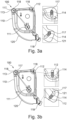
- Fig. 3a and Fig. 3b show, respectively, that the retention elements 118 of the first bracket portion 110 may comprise a sliding slot 112 at one of the two through holes 117 and a pivot element 113 at the other of the two through holes 117.
- the retention element 118 of the second bracket portion may, for example, be a sliding slot 112. Since the pivot element 113 may be configured to pivot about the respective though hole 117, for example counterclockwise, by a predefined angle 102 during the crash. Accordingly, by the crash, the sliding slot 112 of the first bracket portion 110 and the sliding slot 112 of the second bracket portion 120 may allow the respective fixing elements 114 to slide from the respective through holes 117 into the sliding slots 112.
- the pivot element 113 may pivot counterclockwise by the predefined angle and the first bracket portion 110 may twist by the corresponding predefined angle 102.
- the counterclockwise pivot direction may ensure that the accelerator pedal 210 and the foot 55 placed thereon may twist from a first position to a second position, so that the foot 55 during the crash may not be further injured by a brake pedal 300 as shown in Fig. 4a to Fig. 4c that is typically provided on the left side of the accelerator pedal 210.
- the sliding slot 112 of the second bracket portion 120 may elongate the respective through hole 117 in a second direction that may differ from the first elongation direction of the sliding slot 112 of the first bracket portion 110.
- the second bracket portion 120 may be secured to the first bracket portion so that the pedal bracket 100 may twist as a whole piece.
- the pedal bracket assembly may allow the accelerator pedal 210 and the foot 55 placed thereon to slide, rotate or twist from the first position into the second position during the crash, in addition to being lifted up by the deformation element 111, the crash force or the crash pulse on the accelerator pedal 210 and the foot 55 may further be absorbed and reduced and the extent of the foot injury of the driver may thus be further minimized.
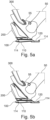
- Fig. 4a to Fig. 4c and Fig. 5a to Fig. 5c show, respectively, an accelerating pedal assembly 200 for protecting a driver 50 during a crash in a perspective view and a side view.
- the accelerating pedal assembly 200 comprises an accelerator pedal 210, which is arranged on the right side to a brake pedal 300 and on which the foot 55 of the driver 50 may be placed, and an accelerator pedal bracket assembly 100 which is shown in Fig. 1 to Fig. 3 for example.
- the accelerator pedal bracket assembly 100 may be configured to secure the accelerator pedal 210 to a floor panel of the vehicle 10 by means of at least one fixing element 114, so that the accelerator pedal 210 may be designed to be a flexible hanging pedal 210.
- the fixing elements 114 may be provided at the through holes 117 of the accelerator pedal bracket assembly 100.
- the accelerator pedal bracket assembly 100 may comprise a deformation element 111 which may be configured to allow the accelerator pedal 210 and the foot 55 thereon being lifted up by a predefined height 101, as shown in Fig. 4b , and/or at least one retention element 118 which may be configured to allow the accelerator pedal 210 and the foot twisting by a predefined angle 102, as shown in Fig. 4c .
- the accelerator pedal bracket assembly 100, the accelerator pedal 210 and the foot 55 may twist from a first position to a second position where the foot 55 may be distant to the side panel of the vehicle with a predefined distance 103, as shown in Fig. 4b and Fig. 5b , so that the foot 55 may be prevented from a further injury caused by the side panel during the crash.
- a maximum predefined distance 103 between the accelerator pedal 210 and the side panel may prevent the foot 55 from slipping off the accelerator pedal 210 at the right side of the accelerator pedal 210.
- the accelerator pedal 210 may twist to guide the foot 55 to the right side of the accelerator pedal 210, in order to prevent the foot 55 to slip off the accelerator pedal 210 at the left side of the accelerator pedal 210.
- Fig. 6 shows that the vehicle 10 comprises an accelerating pedal assembly 200 according to the present disclosure.
- the accelerating pedal assembly 200 may comprise an accelerator pedal bracket assembly 100 according to the present disclosure and a processing element 80, which may be designed to execute a computer program element for the vehicle 10 for performing method steps as shown in Fig. 7 .
- Fig. 7 shows a flow chart illustrating a method for protecting a driver 50 during a crash for a vehicle 10 by means of an accelerator pedal bracket assembly 100.
- the method starts at step 710 where a first bracket portion 110 comprising a deformation element 111 and a protruding surface 115 may be provided and an accelerator pedal 210 may be supported by means of the protruding surface 115.
- the deformation element 111 which is arranged in a deformation zone 111a on the protruding surface 115, may be deformed during the crash, in order to lift the accelerator pedal 210 up by a predefined height 101.
- the first bracket portion 110 may be able to slide or twist during the crash by means of at least one retention element 118 that may comprise at least one sliding slot 112 and/or at least one pivot element 113.
- a computer program may be stored/distributed on a suitable medium such as an optical storage medium or a solid-state medium supplied together with or as part of other hardware, but may also be distributed in other forms, such as via the Internet or other wired or wireless telecommunication systems. Any reference signs in the claims should not be construed as limiting the scope of the claims.
Landscapes
- Engineering & Computer Science (AREA)
- Mechanical Engineering (AREA)
- Chemical & Material Sciences (AREA)
- Combustion & Propulsion (AREA)
- Transportation (AREA)
- Physics & Mathematics (AREA)
- General Physics & Mathematics (AREA)
- Automation & Control Theory (AREA)
- Mechanical Control Devices (AREA)
- Auxiliary Drives, Propulsion Controls, And Safety Devices (AREA)
Abstract
Description
- The present disclosure relates to an accelerator pedal bracket assembly for a vehicle for protecting a driver during a crash, an accelerating pedal assembly for a vehicle for protecting a driver during a crash, a vehicle comprising an accelerator pedal bracket assembly, the use of an accelerator pedal bracket assembly for a vehicle and a method for protecting a driver by means of an accelerator pedal bracket assembly.
- In a belted or unbelted vehicle collision accident, the driver often still has his foot placed on a pedal of the vehicle. The G-force in such a collision may exert a high impact on the pedal and the foot thereon. Statistically, the G-force exerted on the foot of the driver by such a collision may be as high as about 3500 N. However, at this force level, the pedal of the vehicle may not be completely damaged or deformed, so that the force pulse on the foot placed thereon may not be absorbed or reduced enough and thereby cause a severe injury of the driver during the collision. Moreover, the pedal may be damaged and fall apart into small pieces, resulting in further injuring the foot of the driver placed on the pedal. Hence, a sufficient protection system needs to be developed for the driving system of the vehicle, in order to keep the risk and the extent of an injury of the driver caused by the vehicle collision at a minimum.
- It is an objective of the present disclosure to provide an improved pedal assembly for a vehicle for safety protection by a collision.
- The problem is at least partially solved or alleviated by the subject matter of the independent claims of the present disclosure, wherein further examples are incorporated in the dependent claims.
- According to a first aspect, there is provided an accelerator pedal assembly for a vehicle for protecting a driver during a crash. The accelerator pedal assembly comprises a first bracket portion, which comprises a deformation element and a protruding surface. The protruding surface is configured to support an accelerator pedal. The deformation element is arranged in a deformation zone on the protruding surface and configured to be deformed during the crash and to lift the accelerator pedal up by a predefined height.
- The deformation element may be designed to be one or more recesses, slits or in combination, which may be formed on the protruding surface to facilitate the deformation in the deformation zone when compared to the zone on the protruding surface other than the deformation zone. Alternatively, the deformation element may be designed to be a protrusion on the protruding surface. Alternatively, the deformation element may be a resilient element that may be designed to lift the accelerator pedal up by means of the spring force of the resilient element during the crash.
- By deforming the deformation element of the first bracket portion of the accelerator pedal bracket assembly, the high initial pulse of the collision, which may be for example around 3500 N on the foot, may be absorbed or brought down to a lower level and the injury caused by the crash may be prevented or at least kept at a minimum. Furthermore, by deforming the deformation element, the damage of the accelerator pedal may be minimized and the accelerator pedal may not fall into loose parts.
- In an example, the first bracket portion may further comprise a base that may comprise at least one through hole and at least one retention element. The at least one through hole may be configured to secure the accelerator pedal to a floor panel of the vehicle by means of at least one fixing element.
- The at least one retention element may be arranged at the at least one through hole.
- The deformation elements and/or the retention elements may be cost-efficiently formed on the protruding surface of the pedal bracket, so that the optimized protection for the foot of the driver may be achieved during the crash without modifying the accelerator pedal itself.
- In an example, the at least one retention element may comprise at least one sliding slot, which may be configured to elongate the at least one through hole in a first direction. The at least one sliding slot may be configured to allow the at least one fixing element sliding from the at least one through hole into the at least one sliding slot during the crash.
- In an example, the at least one retention element may be configured to elongate the at least one through hole in parallel to each other. The at least one sliding slot may be configured to allow the at least one fixing element sliding from the at least one through hole into the at least one sliding slot in the same first direction during the crash.
- The lateral translational movement, in addition to the vertical lifting up movement, of the accelerator pedal bracket assembly may further absorb and reduce the force exerted on the accelerator pedal and the foot thereon during the crash, resulting in minimized foot injury.
- In an example, the at least one retention element may be configured to elongate the at least one through hole antiparallel to each other. Additionally, the at least one sliding slot may be configured to allow the at least one sliding slot sliding in opposite directions and thereby to allow the first bracket portion twisting by a predefined angle during the crash.
- Similarly, the lateral twisting movement, in addition to the vertical lifting up movement, of the accelerator pedal bracket assembly may further absorb and reduce the force exerted on the accelerator pedal and the foot thereon during the crash, resulting in minimized foot injury.
- In an example, the at least one retention element may further comprise at least one pivot element, which may be configured to pivot about the at least one through hole by the predefined angle during the crash.
- Similarly, the lateral pivot or rotation movement, in addition to the vertical lifting up movement, of the accelerator pedal bracket assembly may further absorb and reduce the force exerted on the accelerator pedal and the foot thereon during the crash, resulting in minimized foot injury.
- In an example, the at least one retention element may be configured to allow the sliding slot sliding into the sliding slot during the crash. Additionally, the at least one retention element may be configured to allow the pivot element pivoting by the predefined angle and thereby allow the first bracket portion twisting by the predefined angle during the crash.
- In an example, the predefined height may be 1 mm to 2 mm.
- In an example, the accelerator pedal bracket assembly may further comprise a second bracket portion, which may comprise the through hole and be configured to be at least partially overlaid by the first bracket portion.
- The first bracket portion may be designed to be movable independently from the second bracket portion, so that the sliding slots of the first bracket portion may be configured to allow the respective fixing elements to slide or move in opposite directions.
- In an example, the second bracket portion may be secured to the first bracket portion.
- Alternatively or additionally, the second bracket portion and the first bracket portion may be designed to be one piece.
- The second bracket portion and the first bracket portion may form an integral piece of the accelerator pedal bracket, so that the accelerator pedal bracket may be lifted up, move or rotate as a whole piece.
- In an example, the second bracket portion may further comprise the retention element, which may be the sliding slot.
- The sliding slot of the second bracket portion may be configured to elongate the through hole of the second bracket portion in parallel to the at least one retention element of the first bracket portion, and thereby to allow the fixing element of the second bracket portion sliding from the through hole into the sliding slot in the same first direction as the at least one fixing element of the first bracket portion during the crash.
- Alternatively, the sliding slot of the second bracket portion may be configured to elongate the through hole of the second bracket portion in a second direction different from the first direction, and to allow the fixing element of the second bracket portion sliding in the second direction, thereby to allow the second bracket portion twisting by the predefined angle, when the first bracket portion twisting by the predefined angle during the crash.
- According to the second aspect, there is provided an accelerating pedal assembly for a vehicle for protecting a driver during a crash. The accelerating pedal assembly comprises an accelerator pedal and an accelerator pedal bracket assembly according to the present disclosure. The accelerator pedal bracket assembly is configured to secure the accelerator pedal to a floor panel of the vehicle and comprises a deformation element, which is configured to be deformed during the crash, so that the accelerator pedal and a foot of the driver are lifted up by a predefined height.
- Alternatively or additionally, the accelerator pedal bracket assembly may further comprise a first bracket portion, which may comprise at least one retention element comprising at least one sliding slot and/or at least one pivot element. The at least one sliding slot may be configured to allow the at least one fixing element, which may be configured to be arranged at the at least one through hole of the first bracket portion and attach the accelerator pedal to the floor panel, sliding from the at least one through hole into the at least one sliding slot or twisting by a predefined angle during the crash. The at least one pivot element may be configured to pivot about the at least one through hole by a predefined angle.
- The accelerator pedal bracket assembly may be arranged between the accelerator pedal and the floor panel of the vehicle, so that the accelerator pedal may be designed to be a hanging pedal. This may advantageously allow the accelerator pedal and the foot of the driver placed on the accelerator pedal sliding off during a crash, so that the foot injury may be prevented or at least minimized, since the pulse of the crash on foot may fully or at least partly absorbed by the movable hanging accelerator pedal and the foot may be moved to a relatively stable and safe position during the crash.
- Further, the accelerator pedal bracket assembly, the accelerator pedal and the foot may twist from a first position to a second position, so that the foot may be distant to the side panel of the vehicle with a predefined distance. As such, the foot may be prevented from a further injury caused by the side panel during the crash. A maximum predefined distance may be provided between the accelerator pedal and the side panel for preventing the foot from slipping off the accelerator pedal at the right side of the accelerator pedal. Moreover, the accelerator pedal may be configured to twist to guide the foot to the right side of the accelerator pedal for preventing the foot from slipping off the accelerator pedal at the left side of the accelerator pedal.
- According to a third aspect, there is provided the use of an accelerator pedal bracket assembly according to the present disclosure for a vehicle according to the present disclosure for absorbing a crash impact and preventing a foot injury of a driver during a crash.
- According to a fourth aspect, there is provided a vehicle comprising an accelerating pedal assembly according to the present disclosure, which comprises an accelerator pedal bracket assembly according to the present disclosure.
- The accelerating pedal assembly and the accelerator pedal bracket assembly may be securely mounted to and/or integrated in the vehicle.
- According to a fifth aspect, there is provided a method for protecting a driver during a crash for a vehicle by means of an accelerator pedal bracket assembly according to the present disclosure. The method comprises the following steps: first, providing a first bracket portion that comprises a deformation element and a protruding surface, and supporting an accelerator pedal by means of the protruding surface; subsequently, deforming the deformation element which is arranged in a deformation zone on the protruding surface during the crash, in order to lift the accelerator pedal up by a predefined height; finally, sliding or twisting the first bracket portion during the crash by means of at least one retention element, which comprises at least one sliding slot and/or at least one pivot element.
- Further, there may be provided a computer program element for an accelerator pedal bracket assembly, which, when being executed by a processing element of a vehicle, is adapted to perform the method steps of the fifth aspect.
- The method may be at least partly computer-implemented, and may be implemented in software or in hardware, or in software and hardware. Further, the method may be carried out by computer program instructions running on means that provide data processing functions. The data processing means may be a suitable computing means, such as an electronic control module etc., which may also be a distributed computer system. The data processing means or the computer, respectively, may comprise one or more of a processor, a memory, a data interface, or the like.
- It should be noted that the above examples may be combined with each other irrespective of the aspect involved. Accordingly, the method may be combined with structural features and, likewise, the apparatus and the system may be combined with features described above with regard to the method.
- These and other aspects of the present disclosure will become apparent from and elucidated with reference to the examples described hereinafter.
- Examples of the disclosure will be described in the following with reference to the following drawings.
- Fig. 1
- shows schematically an example of an accelerator pedal bracket assembly according to the present disclosure.
- Fig. 2
- shows schematically an example of an accelerator pedal bracket assembly according to the present disclosure.
- Fig. 3a
- shows schematically an example of an accelerator pedal bracket assembly according to the present disclosure.
- Fig. 3b
- shows schematically an example of an accelerator pedal bracket assembly according to the present disclosure.
- Fig. 4a
- shows schematically a perspective view of an example of an accelerating pedal assembly according to the present disclosure.
- Fig. 4b
- shows schematically a perspective view of an example of an accelerating pedal assembly according to the present disclosure.
- Fig. 4c
- shows schematically a perspective view of an example of an accelerating pedal assembly according to the present disclosure.
- Fig. 5a
- shows schematically a side view of an example of an accelerating pedal assembly according to the present disclosure.
- Fig. 5b
- shows schematically a side view of an example of an accelerating pedal assembly according to the present disclosure.
- Fig. 6
- shows schematically an example of a vehicle according to the present disclosure.
- Fig. 7
- shows schematically a flow chart illustrating a method for soundproofing in a vehicle by means of an audio controlling system according to the present disclosure.
- The figures are merely schematic representations and serve only to illustrate examples of the disclosure. Identical or equivalent elements are in principle provided with the same reference signs.
-
Fig. 1 shows an acceleratorpedal bracket assembly 100 for avehicle 10, which is also shown inFig. 6 , for protecting adriver 50 during a crash. The acceleratorpedal bracket assembly 100 comprises afirst bracket portion 110 and asecond bracket portion 120. - The
first bracket portion 110 comprises adeformation element 111 and aprotruding surface 115. Thedeformation element 111 is arranged in a deformation zone 111a on the protrudingsurface 115. Thedeformation element 111 may be designed to be one or more recesses, slits or in combination, which may be formed on the protrudingsurface 115 to facilitate the deformation in the deformation zone 111a when compared to the zone of the protrudingsurface 115 other than the deformation zone 111a. - The protruding
surface 115 may be configured to support anaccelerator pedal 210, as shown inFig. 4a to Fig. 5a , of thevehicle 10. - The protruding
surface 115 may be designed to be in a substantially rectangular form, which may correspond to the bottom surface of anaccelerator pedal 210. The deformation zone 111a for the deformation element is arranged in a zone in one of the corners of the protrudingsurface 115. Alternatively, the deformation zone 111a may be arranged in the center zone of the protrudingsurface 115. - The
deformation element 111, may be configured to be deformed during the crash and to lift theaccelerator pedal 210 up by apredefined height 101. For example, the definedheight 101 may be 1 mm to 2 mm. - By deforming the
deformation element 111 of thefirst bracket portion 110 of the acceleratorpedal bracket assembly 100, the high initial pulse of the collision, which may be around 3500 N on thefoot 55 may be absorbed or brought down to a lower level and the injury caused by the crash may be prevented or at least kept at a minimum. Furthermore, by deforming thedeformation element 111, the damage of theaccelerator pedal 210 may be minimized and theaccelerator pedal 210 may not fall into loose parts. - Moreover, the
deformation element 111 may be cost-efficiently formed on the protrudingsurface 115 of the pedal bracket without modifying theaccelerator pedal 210 itself. - The
first bracket portion 110 of the acceleratorpedal bracket assembly 100 further comprises abase 116, which comprises at least one throughhole 117. The at least one throughhole 117 may be configured to secure theaccelerator pedal 210 to a floor pedal ofvehicle 10 by means of at least one fixing element as shown inFig. 3a and Fig. 3b , such as at least one screw or at least one pin. InFig. 1 , two throughholes 117 are provided, respectively, in the two corners of thefirst bracket portion 110 to allow theaccelerator pedal 210 being fixed to the floor panel of thevehicle 10. - The
second bracket portion 120 of the acceleratorpedal bracket assembly 100 comprises an extendingportion 121 and the throughhole 117 that is arranged in the extendingportion 121. - The
second bracket portion 120 may be secured to thefirst bracket portion 110. For example, thesecond bracket portion 120 and thefirst bracket portion 110 may be designed to be one piece, so that thesecond bracket portion 120 and thefirst bracket portion 110 may be movable as a whole during the crash. - Alternatively, the
second bracket portion 120 may be designed to be at least partially overlaid by thefirst bracket portion 110, so that only thefirst bracket portion 110 may be movable during the crash. - In contrast to the accelerator
pedal bracket assembly 100 ofFig. 1 , thebase 116 of thefirst bracket portion 110 of the acceleratorpedal bracket assembly 100 inFig. 2 further comprises at least oneretention element 118, which are arranged at the at least one throughhole 117. As shown inFig. 2 , tworetention elements 118 are provided, respectively, at the two throughholes 117 of thebase 116 of thefirst bracket portion 110. Additionally, afurther retention element 118 is arranged at the throughhole 117 of thesecond bracket portion 120. - The at least one
retention element 118 may comprise at least one slidingslot 112 that may elongate or extend the at least one throughhole 117. For example, inFig. 2 , three slidingslots 112 are provided, respectively, at the threecorresponding retention elements 117. As thesecond bracket portion 120 may be secured to thefirst bracket portion 110 or formed as an integral piece with thefirst bracket portion 110, the slidingslots 112 may be configured to allow the respective fixingelements 114 to slide from the respective throughholes 117 into the slidingslots 112 during the crash. - All three sliding
slots 112 are designed to elongate the respective throughholes 117 in the same direction, namely a first direction. In this way, theretention elements 118 may be configured to elongate the throughholes 117 in parallel to each other. Accordingly, the sliding slots may be configured to allow the fixingelements 114 to slide or move from the throughholes 117 into the slidingslots 112 in the same first direction, so that thebracket assembly 100 may be moved translationally as a whole piece from a first position to a second position. - Alternatively, the two
retention elements 118 of thefirst bracket portion 110 may be configured to elongate the throughholes 117 antiparallel to each other. If thefirst bracket portion 110 is designed to be movable independently from thesecond bracket portion 120, the slidingslots 112 of thefirst bracket portion 110 may be configured to allow the respective fixingelements 114 to slide or move in opposite directions. Accordingly, thefirst bracket portion 110 may twist or pivot by apredefined angle 102, e.g. as shown inFig. 4c , by a predefined angle during the crash. - Alternatively, the at least one
retention element 118 may further comprise at least onepivot element 113, which may be configured to pivot about the at least one throughhole 117 by apredefined angle 102 during the crash. -
Fig. 3a and Fig. 3b show, respectively, that theretention elements 118 of thefirst bracket portion 110 may comprise a slidingslot 112 at one of the two throughholes 117 and apivot element 113 at the other of the two throughholes 117. Theretention element 118 of the second bracket portion may, for example, be a slidingslot 112. Since thepivot element 113 may be configured to pivot about the respective thoughhole 117, for example counterclockwise, by apredefined angle 102 during the crash. Accordingly, by the crash, the slidingslot 112 of thefirst bracket portion 110 and the slidingslot 112 of thesecond bracket portion 120 may allow the respective fixingelements 114 to slide from the respective throughholes 117 into the slidingslots 112. Simultaneously, thepivot element 113 may pivot counterclockwise by the predefined angle and thefirst bracket portion 110 may twist by the correspondingpredefined angle 102. The counterclockwise pivot direction may ensure that theaccelerator pedal 210 and thefoot 55 placed thereon may twist from a first position to a second position, so that thefoot 55 during the crash may not be further injured by abrake pedal 300 as shown inFig. 4a to Fig. 4c that is typically provided on the left side of theaccelerator pedal 210. - In
Fig. 3a and Fig. 3b , the slidingslot 112 of thesecond bracket portion 120 may elongate the respective throughhole 117 in a second direction that may differ from the first elongation direction of the slidingslot 112 of thefirst bracket portion 110. Thesecond bracket portion 120 may be secured to the first bracket portion so that thepedal bracket 100 may twist as a whole piece. - Since the pedal bracket assembly may allow the
accelerator pedal 210 and thefoot 55 placed thereon to slide, rotate or twist from the first position into the second position during the crash, in addition to being lifted up by thedeformation element 111, the crash force or the crash pulse on theaccelerator pedal 210 and thefoot 55 may further be absorbed and reduced and the extent of the foot injury of the driver may thus be further minimized. -
Fig. 4a to Fig. 4c andFig. 5a to Fig. 5c show, respectively, an acceleratingpedal assembly 200 for protecting adriver 50 during a crash in a perspective view and a side view. - The accelerating
pedal assembly 200 comprises anaccelerator pedal 210, which is arranged on the right side to abrake pedal 300 and on which thefoot 55 of thedriver 50 may be placed, and an acceleratorpedal bracket assembly 100 which is shown inFig. 1 to Fig. 3 for example. - The accelerator
pedal bracket assembly 100 may be configured to secure theaccelerator pedal 210 to a floor panel of thevehicle 10 by means of at least one fixingelement 114, so that theaccelerator pedal 210 may be designed to be aflexible hanging pedal 210. The fixingelements 114 may be provided at the throughholes 117 of the acceleratorpedal bracket assembly 100. - The accelerator
pedal bracket assembly 100 may comprise adeformation element 111 which may be configured to allow theaccelerator pedal 210 and thefoot 55 thereon being lifted up by apredefined height 101, as shown inFig. 4b , and/or at least oneretention element 118 which may be configured to allow theaccelerator pedal 210 and the foot twisting by apredefined angle 102, as shown inFig. 4c . - The accelerator
pedal bracket assembly 100, theaccelerator pedal 210 and thefoot 55 may twist from a first position to a second position where thefoot 55 may be distant to the side panel of the vehicle with apredefined distance 103, as shown inFig. 4b andFig. 5b , so that thefoot 55 may be prevented from a further injury caused by the side panel during the crash. A maximumpredefined distance 103 between theaccelerator pedal 210 and the side panel may prevent thefoot 55 from slipping off theaccelerator pedal 210 at the right side of theaccelerator pedal 210. Moreover, theaccelerator pedal 210 may twist to guide thefoot 55 to the right side of theaccelerator pedal 210, in order to prevent thefoot 55 to slip off theaccelerator pedal 210 at the left side of theaccelerator pedal 210. -
Fig. 6 shows that thevehicle 10 comprises an acceleratingpedal assembly 200 according to the present disclosure. The acceleratingpedal assembly 200 may comprise an acceleratorpedal bracket assembly 100 according to the present disclosure and aprocessing element 80, which may be designed to execute a computer program element for thevehicle 10 for performing method steps as shown inFig. 7 . -
Fig. 7 shows a flow chart illustrating a method for protecting adriver 50 during a crash for avehicle 10 by means of an acceleratorpedal bracket assembly 100. The method starts atstep 710 where afirst bracket portion 110 comprising adeformation element 111 and aprotruding surface 115 may be provided and anaccelerator pedal 210 may be supported by means of the protrudingsurface 115. At asubsequent step 720, thedeformation element 111, which is arranged in a deformation zone 111a on the protrudingsurface 115, may be deformed during the crash, in order to lift theaccelerator pedal 210 up by apredefined height 101. Finally, atstep 730, thefirst bracket portion 110 may be able to slide or twist during the crash by means of at least oneretention element 118 that may comprise at least one slidingslot 112 and/or at least onepivot element 113. - Other variations to the disclosed examples can be understood and effected by those skilled in the art in practicing the claimed disclosure, from the study of the drawings, the disclosure, and the appended claims. In the claims the word "comprising" does not exclude other elements or steps and the indefinite article "a" or "an" does not exclude a plurality. A single processor or other unit may fulfill the functions of several items or steps recited in the claims. The mere fact that certain measures are recited in mutually different dependent claims does not indicate that a combination of these measures cannot be used to advantage. A computer program may be stored/distributed on a suitable medium such as an optical storage medium or a solid-state medium supplied together with or as part of other hardware, but may also be distributed in other forms, such as via the Internet or other wired or wireless telecommunication systems. Any reference signs in the claims should not be construed as limiting the scope of the claims.
-
- 10
- vehicle
- 50
- driver
- 55
- foot of driver
- 80
- processing element
- 100
- accelerator pedal bracket assembly
- 101
- predefined height
- 102
- predefined angle
- 110
- first bracket portion
- 111
- deformation element
- 111a
- deformation zone
- 112
- sliding slot
- 113
- pivot element
- 114
- fixing element
- 115
- protruding surface
- 116
- base
- 117
- through hole
- 118
- retention element
- 120
- second bracket portion
- 121
- extending portion
- 200
- accelerating pedal assembly
- 210
- accelerator pedal
- 300
- brake pedal
- 710
- step of providing first bracket portion
- 720
- step of deforming deformation element
- 730
- step of sliding or twisting first bracket portion
Claims (15)
- An accelerator pedal bracket assembly (100) for a vehicle (10) for protecting a driver (50) during a crash, comprising:a first bracket portion (110) comprisinga deformation element (111), anda protruding surface (115);the protruding surface (115) being configured to support an accelerator pedal (210);the deformation element (111) being arranged in a deformation zone (111a) on the protruding surface (115);the deformation element (111) being configured to be deformed during the crash and lifting the accelerator pedal (210) up by a predefined height (101).
- The accelerator pedal bracket assembly (100) according to claim 1,
the first bracket portion (110) further comprising a base (116), the base (116) comprising:at least one through hole (117), the at least one through hole being configured to secure the accelerator pedal (210) to a floor panel of the vehicle (10) by means of at least one fixing element (114), andat least one retention element (118), the at least one retention element (118) being arranged at the at least one through hole (117). - The accelerator pedal bracket assembly (100) according to claim 2,the at least one retention element (118) comprising at least one sliding slot (112);the at least one sliding slot (112) being configured to elongate the at least one through hole (117) in a first direction; andthe at least one sliding slot (112) being configured to allow the at least one fixing element (114) sliding from the at least one through hole (117) into the at least one sliding slot (112) during the crash.
- The accelerator pedal bracket assembly (100) according to claim 3,the at least one retention element (118) being configured to elongate the at least one through hole (117) in parallel to each other; andthe at least one sliding slot (112) being configured to allow the at least one fixing element (114) sliding from the at least one through hole (117) into the at least one sliding slot (112) in the same first direction during the crash.
- The accelerator pedal bracket assembly (100) according to claim 2 or 3,the at least one retention element (118) being configured to elongate the at least one through hole (117) antiparallel to each other; andthe at least one sliding slot (112) being configured to allow the at least one sliding slot (112) sliding in opposite directions and thereby to allow the first bracket portion (110) twisting by a predefined angle (102) during the crash.
- The accelerator pedal bracket assembly (100) according to one of the claims 2 to 4,the at least one retention element (118) further comprising at least one pivot element (113);the at least one pivot element (113) being configured to pivot about the at least one through hole (117) by the predefined angle (102) during the crash.
- The accelerator pedal bracket assembly (100) according to claim 6,the at least one retention element (118) being configured to allow the sliding slot (112) sliding into the sliding slot (112) during the crash; andthe at least one retention element (118) being configured to allow the pivot element (113) pivoting by the predefined angle (102) and thereby allow the first bracket portion (110) twisting by the predefined angle (102) during the crash.
- The accelerator pedal bracket assembly (100) according to one of the preceding claims, the predefined height (101) being 1 mm to 2 mm.
- The accelerator pedal bracket assembly (100) according to one of the preceding claims, further comprising:a second bracket portion (120);the second bracket portion (120) comprising the through hole (117) and being configured to be at least partially overlaid by the first bracket portion (110).
- The accelerator pedal bracket assembly (100) according to claim 9,the second bracket portion (120) being secured to the first bracket portion (110); and/orthe second bracket portion (120) and the first bracket portion (110) being designed to be one piece.
- The accelerator pedal bracket assembly (100) according to claim 9,the second bracket portion (120) further comprising the retention element (118), the retention element (118) of the second bracket portion (120) being the sliding slot (112);the sliding slot (112) of the second bracket portion (120) being configured to elongate the through hole (117) of the second bracket portion (120) in parallel to the at least one retention element (118) of the first bracket portion (110), and thereby to allow the fixing element (114) of the second bracket portion (120) sliding from the through hole (117) into the sliding slot (112) in the same first direction as the at least one fixing element (114) of the first bracket portion (110) during the crash; orthe sliding slot (112) of the second bracket portion (120) being configured to elongate the through hole (117) of the second bracket portion (120) in a second direction different from the first direction, and to allow the fixing element (114) of the second bracket portion (120) sliding in the second direction, thereby to allow the second bracket portion (110) twisting by the predefined angle (102) when the first bracket portion (110) twisting by the predefined angle (102) during the crash.
- An accelerating pedal assembly (200) for a vehicle (10) for protecting a driver (50) during a crash, comprising:an accelerator pedal (210), andan accelerator pedal bracket assembly (100) according to one of the preceding claims 1 to 11;the accelerator pedal bracket assembly (100) being configured to secure the accelerator pedal (210) to a floor panel of the vehicle (10) and comprising a deformation element (111); andthe deformation element (111) being configured to be deformed during the crash, so that the accelerator pedal (200) and a foot (55) of the driver (50) are lifted up by a predefined height (101).
- A vehicle (10) comprising an accelerating pedal assembly (200) according to claim 12, the accelerating pedal assembly (200) comprising an accelerator pedal bracket assembly (100) according to one of the preceding claims 1 to 11.
- Use of an accelerator pedal bracket assembly (100) according to one of the preceding claims 1 to 11 for a vehicle (10) according to claim 13 for absorbing a crash impact and preventing a foot injury of a driver (50) during a crash.
- A method for protecting a driver (50) during a crash for a vehicle (10) by means of an accelerator pedal bracket assembly (100), the method comprising the steps of:providing (710) a first bracket portion (110) comprising a deformation element (111) and a protruding surface (115) and supporting an accelerator pedal (210) by means of the protruding surface (115);deforming (720) the deformation element (111) arranged in a deformation zone (111a) on the protruding surface during the crash, in order to lift the accelerator pedal (210) up by a predefined height (101); andsliding or twisting (730) the first bracket portion (110) during the crash by means of at least one retention element (118), the retention element (118) comprising at least one sliding slot (112) and/or at least one pivot element (113).
Priority Applications (3)
| Application Number | Priority Date | Filing Date | Title |
|---|---|---|---|
| EP22214326.5A EP4385786A1 (en) | 2022-12-16 | 2022-12-16 | Accelerator pedal bracket assembly for a vehicle, accelerating pedal assembly for a vehicle, vehicle comprisng accelerating pedal assembly with accelerator pedal bracket assembly and method for protecting a driver with accelerato pedal bracket assembly |
| CN202311726821.9A CN118205389A (en) | 2022-12-16 | 2023-12-15 | Accelerator pedal bracket assembly of vehicle, accelerator pedal assembly, vehicle, and method for protecting driver using accelerator pedal bracket assembly |
| US18/543,122 US12365242B2 (en) | 2022-12-16 | 2023-12-18 | Accelerator pedal assembly for a vehicle |
Applications Claiming Priority (1)
| Application Number | Priority Date | Filing Date | Title |
|---|---|---|---|
| EP22214326.5A EP4385786A1 (en) | 2022-12-16 | 2022-12-16 | Accelerator pedal bracket assembly for a vehicle, accelerating pedal assembly for a vehicle, vehicle comprisng accelerating pedal assembly with accelerator pedal bracket assembly and method for protecting a driver with accelerato pedal bracket assembly |
Publications (1)
| Publication Number | Publication Date |
|---|---|
| EP4385786A1 true EP4385786A1 (en) | 2024-06-19 |
Family
ID=84537748
Family Applications (1)
| Application Number | Title | Priority Date | Filing Date |
|---|---|---|---|
| EP22214326.5A Pending EP4385786A1 (en) | 2022-12-16 | 2022-12-16 | Accelerator pedal bracket assembly for a vehicle, accelerating pedal assembly for a vehicle, vehicle comprisng accelerating pedal assembly with accelerator pedal bracket assembly and method for protecting a driver with accelerato pedal bracket assembly |
Country Status (3)
| Country | Link |
|---|---|
| US (1) | US12365242B2 (en) |
| EP (1) | EP4385786A1 (en) |
| CN (1) | CN118205389A (en) |
Citations (4)
| Publication number | Priority date | Publication date | Assignee | Title |
|---|---|---|---|---|
| DE10306103A1 (en) * | 2003-02-14 | 2004-09-09 | Audi Ag | Vehicle pedal structure for a pedal mechanism bearing frame in a motor vehicle has a base plate fastened on a front panel and an accelerator pedal module platform part molded on the base-plate |
| DE102008046652A1 (en) * | 2007-10-29 | 2009-04-30 | Volkswagen Ag | Foot pedal i.e. accelerator pedal, for motor vehicle, has damper supplied with force by plate supported at foot of vehicle driver operating pedal due to crash event and intrusion of pedal into interior space of compartment of vehicle |
| US20090293666A1 (en) * | 2008-06-02 | 2009-12-03 | Hyundai Motor Company | Organ Type Accelerator Pedal Apparatus |
| DE102011051406A1 (en) * | 2011-06-28 | 2013-01-03 | Ab Elektronik Gmbh | Vehicle pedal assembly has pedal element and energy consumption element that are arranged such that energy is absorbed by energy consumption element during crash |
Family Cites Families (9)
| Publication number | Priority date | Publication date | Assignee | Title |
|---|---|---|---|---|
| US6327930B1 (en) * | 1996-12-11 | 2001-12-11 | Toyota Jidosha Kabushiki Kaisha | Pedal displacement-control structure for a vehicle |
| DE19652014C2 (en) * | 1996-12-13 | 2003-02-06 | Opel Adam Ag | Pedal mounting for a motor vehicle |
| DE10222106A1 (en) * | 2002-05-17 | 2004-01-22 | Fico Cables, S.A., Rubi | Pedal security system |
| KR101055086B1 (en) * | 2008-12-03 | 2011-08-08 | 기아자동차주식회사 | Organ accelerator pedal |
| KR101509990B1 (en) * | 2013-11-27 | 2015-04-07 | 현대자동차주식회사 | Apparatus for reducing effort of clutch pedal |
| KR101710542B1 (en) * | 2016-03-28 | 2017-03-13 | 씨제이오토모티브(유) | Device for preventing the pedal is pushed |
| SE541759C2 (en) * | 2017-06-22 | 2019-12-10 | Cj Automotive Ab | Pedal assembly with safety position for motor vehicle |
| CN109278724A (en) * | 2018-11-21 | 2019-01-29 | 东风(十堰)车身部件有限责任公司 | Crushing structure of a brake pedal |
| EP4407404A1 (en) * | 2023-01-27 | 2024-07-31 | Volvo Car Corporation | Pedal assembly for a vehicle, drive-by-wire system for a vehicle, and vehicle |
-
2022
- 2022-12-16 EP EP22214326.5A patent/EP4385786A1/en active Pending
-
2023
- 2023-12-15 CN CN202311726821.9A patent/CN118205389A/en active Pending
- 2023-12-18 US US18/543,122 patent/US12365242B2/en active Active
Patent Citations (4)
| Publication number | Priority date | Publication date | Assignee | Title |
|---|---|---|---|---|
| DE10306103A1 (en) * | 2003-02-14 | 2004-09-09 | Audi Ag | Vehicle pedal structure for a pedal mechanism bearing frame in a motor vehicle has a base plate fastened on a front panel and an accelerator pedal module platform part molded on the base-plate |
| DE102008046652A1 (en) * | 2007-10-29 | 2009-04-30 | Volkswagen Ag | Foot pedal i.e. accelerator pedal, for motor vehicle, has damper supplied with force by plate supported at foot of vehicle driver operating pedal due to crash event and intrusion of pedal into interior space of compartment of vehicle |
| US20090293666A1 (en) * | 2008-06-02 | 2009-12-03 | Hyundai Motor Company | Organ Type Accelerator Pedal Apparatus |
| DE102011051406A1 (en) * | 2011-06-28 | 2013-01-03 | Ab Elektronik Gmbh | Vehicle pedal assembly has pedal element and energy consumption element that are arranged such that energy is absorbed by energy consumption element during crash |
Also Published As
| Publication number | Publication date |
|---|---|
| CN118205389A (en) | 2024-06-18 |
| US12365242B2 (en) | 2025-07-22 |
| US20240198796A1 (en) | 2024-06-20 |
Similar Documents
| Publication | Publication Date | Title |
|---|---|---|
| CN1295106C (en) | Crew member protector | |
| CN114261364B (en) | Roof airbag systems and vehicles | |
| EP0639124A1 (en) | Safety seat | |
| JP4752453B2 (en) | Spare tire storage structure | |
| US20240198796A1 (en) | Accelerator pedal assembly for a vehicle | |
| CN107433913B (en) | Mounting bracket for console | |
| JP7119966B2 (en) | forklift | |
| CN113825673B (en) | Controlled separation feature for steering column mounted camera | |
| CN114750717A (en) | Vehicle seat back adjusting method, device, equipment and storage medium | |
| US10086794B2 (en) | Load limiting retractor with hall effect switch | |
| EP4286315B1 (en) | Elevator car with moving electrical box | |
| JP4054996B2 (en) | Knee airbag module mounting structure | |
| US20200398713A1 (en) | Motor vehicle seat and method for absorbing energy in a motor vehicle seat | |
| KR102634408B1 (en) | Seat belt for protecting submarine accident in automobile and operating method thereof | |
| JP4036079B2 (en) | Vehicle footrest structure | |
| KR101262970B1 (en) | Mounting bracket for seatback frame and seat frame unit for vehicle | |
| JP6646889B2 (en) | Vehicle undercarriage | |
| KR101593524B1 (en) | Impact absorbing seat frame | |
| KR102508399B1 (en) | Electronic control device and its manufacturing method | |
| KR102845394B1 (en) | Wheelchair securing apparatus for vehicle | |
| CN114572139B (en) | Passenger self-adaptive lower limb restraint system and method and vehicle | |
| JP2001150984A (en) | Leg structure of seat slide device | |
| KR101393500B1 (en) | Apparatus for folding seat cushion | |
| KR200366668Y1 (en) | A guide anchor for seat belt of vehicle | |
| KR100599700B1 (en) | Vehicle anti-submarine system |
Legal Events
| Date | Code | Title | Description |
|---|---|---|---|
| PUAI | Public reference made under article 153(3) epc to a published international application that has entered the european phase |
Free format text: ORIGINAL CODE: 0009012 |
|
| STAA | Information on the status of an ep patent application or granted ep patent |
Free format text: STATUS: REQUEST FOR EXAMINATION WAS MADE |
|
| 17P | Request for examination filed |
Effective date: 20230927 |
|
| AK | Designated contracting states |
Kind code of ref document: A1 Designated state(s): AL AT BE BG CH CY CZ DE DK EE ES FI FR GB GR HR HU IE IS IT LI LT LU LV MC ME MK MT NL NO PL PT RO RS SE SI SK SM TR |
|
| GRAP | Despatch of communication of intention to grant a patent |
Free format text: ORIGINAL CODE: EPIDOSNIGR1 |
|
| STAA | Information on the status of an ep patent application or granted ep patent |
Free format text: STATUS: GRANT OF PATENT IS INTENDED |
|
| RIC1 | Information provided on ipc code assigned before grant |
Ipc: B60K 26/02 20060101AFI20260331BHEP |