EP4383604A1 - Verfahren und vorrichtung zum senden oder empfangen eines signals in einem kommunikationssystem - Google Patents
Verfahren und vorrichtung zum senden oder empfangen eines signals in einem kommunikationssystem Download PDFInfo
- Publication number
- EP4383604A1 EP4383604A1 EP22867573.2A EP22867573A EP4383604A1 EP 4383604 A1 EP4383604 A1 EP 4383604A1 EP 22867573 A EP22867573 A EP 22867573A EP 4383604 A1 EP4383604 A1 EP 4383604A1
- Authority
- EP
- European Patent Office
- Prior art keywords
- sequence
- length
- bit
- operating unit
- bit sequence
- Prior art date
- Legal status (The legal status is an assumption and is not a legal conclusion. Google has not performed a legal analysis and makes no representation as to the accuracy of the status listed.)
- Pending
Links
Images






Classifications
-
- H—ELECTRICITY
- H04—ELECTRIC COMMUNICATION TECHNIQUE
- H04L—TRANSMISSION OF DIGITAL INFORMATION, e.g. TELEGRAPHIC COMMUNICATION
- H04L1/00—Arrangements for detecting or preventing errors in the information received
- H04L1/12—Arrangements for detecting or preventing errors in the information received by using return channel
- H04L1/16—Arrangements for detecting or preventing errors in the information received by using return channel in which the return channel carries supervisory signals, e.g. repetition request signals
- H04L1/18—Automatic repetition systems, e.g. Van Duuren systems
- H04L1/1812—Hybrid protocols; Hybrid automatic repeat request [HARQ]
-
- H—ELECTRICITY
- H04—ELECTRIC COMMUNICATION TECHNIQUE
- H04L—TRANSMISSION OF DIGITAL INFORMATION, e.g. TELEGRAPHIC COMMUNICATION
- H04L47/00—Traffic control in data switching networks
- H04L47/10—Flow control; Congestion control
- H04L47/34—Flow control; Congestion control ensuring sequence integrity, e.g. using sequence numbers
-
- H—ELECTRICITY
- H03—ELECTRONIC CIRCUITRY
- H03M—CODING; DECODING; CODE CONVERSION IN GENERAL
- H03M13/00—Coding, decoding or code conversion, for error detection or error correction; Coding theory basic assumptions; Coding bounds; Error probability evaluation methods; Channel models; Simulation or testing of codes
- H03M13/03—Error detection or forward error correction by redundancy in data representation, i.e. code words containing more digits than the source words
- H03M13/05—Error detection or forward error correction by redundancy in data representation, i.e. code words containing more digits than the source words using block codes, i.e. a predetermined number of check bits joined to a predetermined number of information bits
- H03M13/11—Error detection or forward error correction by redundancy in data representation, i.e. code words containing more digits than the source words using block codes, i.e. a predetermined number of check bits joined to a predetermined number of information bits using multiple parity bits
- H03M13/1102—Codes on graphs and decoding on graphs, e.g. low-density parity check [LDPC] codes
- H03M13/1148—Structural properties of the code parity-check or generator matrix
- H03M13/116—Quasi-cyclic LDPC [QC-LDPC] codes, i.e. the parity-check matrix being composed of permutation or circulant sub-matrices
-
- H—ELECTRICITY
- H03—ELECTRONIC CIRCUITRY
- H03M—CODING; DECODING; CODE CONVERSION IN GENERAL
- H03M13/00—Coding, decoding or code conversion, for error detection or error correction; Coding theory basic assumptions; Coding bounds; Error probability evaluation methods; Channel models; Simulation or testing of codes
- H03M13/03—Error detection or forward error correction by redundancy in data representation, i.e. code words containing more digits than the source words
- H03M13/05—Error detection or forward error correction by redundancy in data representation, i.e. code words containing more digits than the source words using block codes, i.e. a predetermined number of check bits joined to a predetermined number of information bits
- H03M13/11—Error detection or forward error correction by redundancy in data representation, i.e. code words containing more digits than the source words using block codes, i.e. a predetermined number of check bits joined to a predetermined number of information bits using multiple parity bits
- H03M13/1102—Codes on graphs and decoding on graphs, e.g. low-density parity check [LDPC] codes
- H03M13/1148—Structural properties of the code parity-check or generator matrix
- H03M13/118—Parity check matrix structured for simplifying encoding, e.g. by having a triangular or an approximate triangular structure
- H03M13/1185—Parity check matrix structured for simplifying encoding, e.g. by having a triangular or an approximate triangular structure wherein the parity-check matrix comprises a part with a double-diagonal
- H03M13/1188—Parity check matrix structured for simplifying encoding, e.g. by having a triangular or an approximate triangular structure wherein the parity-check matrix comprises a part with a double-diagonal wherein in the part with the double-diagonal at least one column has an odd column weight equal or greater than three
-
- H—ELECTRICITY
- H03—ELECTRONIC CIRCUITRY
- H03M—CODING; DECODING; CODE CONVERSION IN GENERAL
- H03M13/00—Coding, decoding or code conversion, for error detection or error correction; Coding theory basic assumptions; Coding bounds; Error probability evaluation methods; Channel models; Simulation or testing of codes
- H03M13/25—Error detection or forward error correction by signal space coding, i.e. adding redundancy in the signal constellation, e.g. Trellis Coded Modulation [TCM]
- H03M13/255—Error detection or forward error correction by signal space coding, i.e. adding redundancy in the signal constellation, e.g. Trellis Coded Modulation [TCM] with Low Density Parity Check [LDPC] codes
-
- H—ELECTRICITY
- H03—ELECTRONIC CIRCUITRY
- H03M—CODING; DECODING; CODE CONVERSION IN GENERAL
- H03M13/00—Coding, decoding or code conversion, for error detection or error correction; Coding theory basic assumptions; Coding bounds; Error probability evaluation methods; Channel models; Simulation or testing of codes
- H03M13/27—Coding, decoding or code conversion, for error detection or error correction; Coding theory basic assumptions; Coding bounds; Error probability evaluation methods; Channel models; Simulation or testing of codes using interleaving techniques
- H03M13/2703—Coding, decoding or code conversion, for error detection or error correction; Coding theory basic assumptions; Coding bounds; Error probability evaluation methods; Channel models; Simulation or testing of codes using interleaving techniques the interleaver involving at least two directions
- H03M13/2707—Simple row-column interleaver, i.e. pure block interleaving
-
- H—ELECTRICITY
- H03—ELECTRONIC CIRCUITRY
- H03M—CODING; DECODING; CODE CONVERSION IN GENERAL
- H03M13/00—Coding, decoding or code conversion, for error detection or error correction; Coding theory basic assumptions; Coding bounds; Error probability evaluation methods; Channel models; Simulation or testing of codes
- H03M13/63—Joint error correction and other techniques
- H03M13/6306—Error control coding in combination with Automatic Repeat reQuest [ARQ] and diversity transmission, e.g. coding schemes for the multiple transmission of the same information or the transmission of incremental redundancy
-
- H—ELECTRICITY
- H03—ELECTRONIC CIRCUITRY
- H03M—CODING; DECODING; CODE CONVERSION IN GENERAL
- H03M13/00—Coding, decoding or code conversion, for error detection or error correction; Coding theory basic assumptions; Coding bounds; Error probability evaluation methods; Channel models; Simulation or testing of codes
- H03M13/63—Joint error correction and other techniques
- H03M13/635—Error control coding in combination with rate matching
- H03M13/6356—Error control coding in combination with rate matching by repetition or insertion of dummy data, i.e. rate reduction
-
- H—ELECTRICITY
- H03—ELECTRONIC CIRCUITRY
- H03M—CODING; DECODING; CODE CONVERSION IN GENERAL
- H03M13/00—Coding, decoding or code conversion, for error detection or error correction; Coding theory basic assumptions; Coding bounds; Error probability evaluation methods; Channel models; Simulation or testing of codes
- H03M13/63—Joint error correction and other techniques
- H03M13/635—Error control coding in combination with rate matching
- H03M13/6362—Error control coding in combination with rate matching by puncturing
- H03M13/6368—Error control coding in combination with rate matching by puncturing using rate compatible puncturing or complementary puncturing
- H03M13/6393—Rate compatible low-density parity check [LDPC] codes
-
- H—ELECTRICITY
- H04—ELECTRIC COMMUNICATION TECHNIQUE
- H04L—TRANSMISSION OF DIGITAL INFORMATION, e.g. TELEGRAPHIC COMMUNICATION
- H04L1/00—Arrangements for detecting or preventing errors in the information received
- H04L1/004—Arrangements for detecting or preventing errors in the information received by using forward error control
- H04L1/0041—Arrangements at the transmitter end
-
- H—ELECTRICITY
- H04—ELECTRIC COMMUNICATION TECHNIQUE
- H04L—TRANSMISSION OF DIGITAL INFORMATION, e.g. TELEGRAPHIC COMMUNICATION
- H04L1/00—Arrangements for detecting or preventing errors in the information received
- H04L1/004—Arrangements for detecting or preventing errors in the information received by using forward error control
- H04L1/0045—Arrangements at the receiver end
-
- H—ELECTRICITY
- H04—ELECTRIC COMMUNICATION TECHNIQUE
- H04L—TRANSMISSION OF DIGITAL INFORMATION, e.g. TELEGRAPHIC COMMUNICATION
- H04L1/00—Arrangements for detecting or preventing errors in the information received
- H04L1/004—Arrangements for detecting or preventing errors in the information received by using forward error control
- H04L1/0056—Systems characterized by the type of code used
- H04L1/0057—Block codes
-
- H—ELECTRICITY
- H04—ELECTRIC COMMUNICATION TECHNIQUE
- H04L—TRANSMISSION OF DIGITAL INFORMATION, e.g. TELEGRAPHIC COMMUNICATION
- H04L1/00—Arrangements for detecting or preventing errors in the information received
- H04L1/004—Arrangements for detecting or preventing errors in the information received by using forward error control
- H04L1/0056—Systems characterized by the type of code used
- H04L1/0067—Rate matching
-
- H—ELECTRICITY
- H04—ELECTRIC COMMUNICATION TECHNIQUE
- H04L—TRANSMISSION OF DIGITAL INFORMATION, e.g. TELEGRAPHIC COMMUNICATION
- H04L1/00—Arrangements for detecting or preventing errors in the information received
- H04L1/004—Arrangements for detecting or preventing errors in the information received by using forward error control
- H04L1/0056—Systems characterized by the type of code used
- H04L1/0071—Use of interleaving
-
- H—ELECTRICITY
- H04—ELECTRIC COMMUNICATION TECHNIQUE
- H04L—TRANSMISSION OF DIGITAL INFORMATION, e.g. TELEGRAPHIC COMMUNICATION
- H04L47/00—Traffic control in data switching networks
- H04L47/10—Flow control; Congestion control
- H04L47/36—Flow control; Congestion control by determining packet size, e.g. maximum transfer unit [MTU]
-
- H—ELECTRICITY
- H03—ELECTRONIC CIRCUITRY
- H03M—CODING; DECODING; CODE CONVERSION IN GENERAL
- H03M13/00—Coding, decoding or code conversion, for error detection or error correction; Coding theory basic assumptions; Coding bounds; Error probability evaluation methods; Channel models; Simulation or testing of codes
- H03M13/03—Error detection or forward error correction by redundancy in data representation, i.e. code words containing more digits than the source words
- H03M13/05—Error detection or forward error correction by redundancy in data representation, i.e. code words containing more digits than the source words using block codes, i.e. a predetermined number of check bits joined to a predetermined number of information bits
- H03M13/09—Error detection only, e.g. using cyclic redundancy check [CRC] codes or single parity bit
-
- H—ELECTRICITY
- H04—ELECTRIC COMMUNICATION TECHNIQUE
- H04L—TRANSMISSION OF DIGITAL INFORMATION, e.g. TELEGRAPHIC COMMUNICATION
- H04L1/00—Arrangements for detecting or preventing errors in the information received
- H04L1/0001—Systems modifying transmission characteristics according to link quality, e.g. power backoff
- H04L1/0006—Systems modifying transmission characteristics according to link quality, e.g. power backoff by adapting the transmission format
- H04L1/0007—Systems modifying transmission characteristics according to link quality, e.g. power backoff by adapting the transmission format by modifying the frame length
- H04L1/0008—Systems modifying transmission characteristics according to link quality, e.g. power backoff by adapting the transmission format by modifying the frame length by supplementing frame payload, e.g. with padding bits
Definitions
- the disclosure relates to error-correction codes for correcting or restoring data when errors and loss of data may occur or are likely to occur, due to various causes such as noise, interference, or the like in a process of transmitting or storing data.
- the disclosure relates to encoding and decoding of a low-density parity-check (LDPC) code, and more particularly, to efficiently implementing a method, a procedure and an apparatus for encoding and transmitting a signal in a mobile communication system and a broadcasting system, and a method, a procedure, and an apparatus for receiving and decoding the transmitted signal.
- LDPC low-density parity-check
- a 5G communication system or a pre-5G communication system is referred to as a beyond 4G network communication system or a post LTE (long term evolution) system.
- 5G communication systems are being considered for implementation in ultra-high frequency (mmWave) bands (e.g., 28 GHz or 60 GHz bands).
- mmWave ultra-high frequency
- beamforming massive multiple-input multiple-output
- FD-MIMO full dimensional MIMO
- array antenna analog beamforming
- large-scale antenna technologies are being discussed in the 5G communication systems.
- technologies such as evolved small cell, advanced small cell, cloud radio access network (RAN), ultra-dense network, device-to-device (D2D) communication, wireless backhaul, moving network, cooperative communication, coordinated multi-points (CoMP), and interference cancellation are being developed for the 5G communication systems.
- RAN radio access network
- D2D device-to-device
- CoMP coordinated multi-points
- FQAM frequency shift keying and quadrature amplitude modulation
- SWSC sliding window superposition coding
- ACM advanced coding modulation
- FBMC filter bank multi carrier
- NOMA non-orthogonal multiple access
- SCMA sparse code multiple access
- IoT Internet of Things
- IoE Internet of Everything
- sensing technology wired and wireless communication and network infrastructure, service interface technology, and security technology
- technologies such as sensor network, machine to machine (M2M), and machine type communication (MTC) have been researched for connection between things.
- M2M machine to machine
- MTC machine type communication
- the IoT may be also applied to various fields such as e.g., smart homes, smart buildings, smart cities, smart or connected cars, smart grids, healthcare, smart appliances, advanced medical services and so on, using convergence and combination between existing information technology (IT) and various industries.
- IT information technology
- 5G communication system As such, various attempts have been made to apply the 5G communication system to the IoT network.
- technologies such as a sensor network, machine-to-machine (M2M) communication, machine type communication (MTC), and the like are being implemented by the 5G communication technologies such as e.g., beamforming, MIMO, and array antennas.
- cloud RAN cloud radio access network
- Such an application of a cloud radio access network (cloud RAN) as the big data processing technology described above may be referred to as an example of a convergence between the 5G technology and the IoT technology.
- error correction codes used for communication between transceivers are generally referred to as channel coding or forward error correction (FEC).
- FEC forward error correction
- the transmitter serves to encode a data bit sequence to be transmitted to generate and transmit a codeword bit sequence of a longer length
- the receiver serves to decode the codeword bit sequence mixed with errors or noise to overcome the errors or noise and estimate the dating bit sequence.
- Channel coding schemes used today may include convolutional code, turbo code, low-density parity-check coding (LDPC code), polar code or the like.
- LDPC code shows superior error correction performance compared to other channel coding techniques, as the length of the code increases.
- the LDPC code is more suitable for parallelization in the code structure and its resulting belief-propagation (BP) decoding operation, and thus is very suitable for use in an application system requiring high-throughput.
- BP belief-propagation
- LDPC codes are commonly used in various communication and broadcasting systems such as IEEE 802.11n/ad Wi-Fi, DVB-T2/C2/S2, ATSC 3.0 and so on, and in particular, have recently been adopted and also used in 3GPP New Radio (NR) systems, which are 5G mobile communication systems.
- NR 3GPP New Radio
- the disclosure relates to a method for effectively encoding a signal with an LDPC code and for effectively decoding a signal encoded with the LDPC code.
- the disclosure provides an apparatus and a method for efficiently encoding a signal with a low-density parity-check (LDPC) code in a communication or broadcasting system, and an apparatus and a method for efficiently decoding a signal encoded with the LDPC code.
- LDPC low-density parity-check
- the encoding or decoding operation may be interrupted or may not produce a normal result, in case where a size of an incremental redundancy bit transmitted at a specific time point is less than a minimum unit processed by an LDPC encoder and decoder.
- This problem may occur, in particular, in LDPC encoders and decoders implemented with hardware having a fixed structure, and this problem needs to be addressed because in case that the LDPC encoders and decoders do not function properly due to the above problem, the overall performance and reliability of the system may be lowered.
- a method performed by a receiving device of a communication system comprises obtaining a first sequence based on a received signal; comparing a length of the first sequence with an operating unit; when the length of the first sequence is less than the operating unit, generating a second sequence based on the first sequence; and performing decoding based on the second sequence, wherein the length of the second sequence is greater than or equal to the operating unit.
- a receiving device of a communication system comprises a transceiver; and a controller configured to obtain a first sequence based on a received signal, compare a length of the first sequence with an operating unit, generate a second sequence based on the first sequence when the length of the first sequence is less than the operating unit, and perform decoding based on the second sequence, wherein the length of the second sequence is greater than or equal to the operating unit.
- a method performed by a transmitting device of a communication system comprises identifying a length of a bit sequence for performing transmission; comparing the length of the bit sequence for performing transmission with an operating unit; when the length of the bit sequence for performing the transmission is less than the operating unit, generating a second bit sequence having a length greater than or equal to the operating unit; generating a first bit sequence having a length of the bit sequence for performing the transmission, based on the second bit sequence; and transmitting a signal based on the first bit sequence.
- a transmitting device of a communication system comprises a transceiver; and a controller configured to identify a length of a bit sequence for performing transmission, compare the length of the bit sequence for performing the transmission with an operating unit, when the length of the bit sequence for performing the transmission is less than the operating unit, generate a second bit sequence having a length greater than or equal to the operating unit, generate a first bit sequence having a length of the bit sequence for performing the transmission, based on the second bit sequence, and transmit a signal based on the first bit sequence.
- An apparatus and a method according to various embodiments of the disclosure may normally process an input sequence (bit sequence, LLR sequence, etc.) less than a minimum operating unit determined for an operation of an encoder and a decoder, thereby preventing the encoder and the decoder from stopping or operating incorrectly. Accordingly, the transceiver including the LDPC code encoder and e decoder of the disclosure may operate in a stable condition, thereby improving the reliability of the system.
- These computer program instructions may be stored in a computer-usable or computer-readable memory that may be directed to a computer or other programmable data processing equipment to implement a function in a specific manner, and thus the instructions stored in the computer-usable or computer-readable memory may also produce a manufacturing item including therein instruction means that perform the function described in the flowchart block(s).
- the computer program instructions may be mounted onto a computer or any other programmable data processing equipment, and therefore, the instructions causing the computer or other programmable data processing equipment to perform a series of steps of operation thereon to create a process executable by the computer may also provide steps for performing the functions described in the flowchart block(s).
- each block may represent a module, a segment, or a portion of a code including one or more executable instructions for executing a specified logical function(s).
- the functions mentioned in the blocks may occur out of the sequence. For example, two blocks shown one after another may actually be performed substantially simultaneously, or the blocks may sometimes be performed in reverse order depending on their corresponding functions.
- the term ' ⁇ unit (or part)' used in embodiments of the disclosure may mean software or a hardware component such as e.g., FPGA or ASIC, to perform a certain function.
- the ' ⁇ unit' does not mean that it is limited only to such software or hardware.
- the ' ⁇ unit' may be configured to reside in an addressable storage medium or may be configured to reproduce one or more processors.
- the ' ⁇ unit' may include components such as e.g., software components, object-oriented software components, class components, and task components, processes, functions, attributes, procedures, subroutines, segments of program code, drivers, firmware, micro-codes, circuits, data, databases, data structures, tables, arrays, variables and so on.
- components and the ' ⁇ unit' may be combined into a smaller number of components and ' ⁇ units (or parts)' or may be further separated into additional components and ' ⁇ units (or parts)'.
- the components and ' ⁇ units (or parts)' may be implemented to reproduce one or more CPUs in a device or a secure multimedia card.
- FIG. 1 is a diagram illustrating an example of a wireless communication system according to various embodiments of the disclosure.
- the communication system may include a transmission node (or transmitter or transmitting device) 110 and a reception node (or receiver or receiving device) 120 as a part of devices or nodes using a wireless channel in the wireless communication system according to an embodiment of the disclosure.
- FIG. 1 illustrates one transmission node 110 and one reception node 120, but it is only for illustrative purposes and the disclosure may also be applied to a communication system including a plurality of transmission nodes or a plurality of reception nodes. Further, while the disclosure describes that the transmission node 110 and the reception node 120 are separate entities for convenience of description, the functions of the transmission node 110 and the reception node 120 may be interchangeable. That is, depending on the situation, the transmission node illustrated in FIG.
- the transmission node 110 may be a terminal, and the reception node 120 may be a base station.
- the transmission node 110 may be a base station, and the reception node 120 may be a terminal.
- both the transmission node 110 and the reception node 120 may be a terminal.
- the transmission node 110 may generate a codeword by encoding information bits based on an LDPC code, and the reception node 120 may decode a signal of the received codeword based on the LDPC code.
- the reception node 120 may use an LDPC decoding scheme according to the disclosure, and may perform a syndrome check to determine whether its decoding result is normal.
- the transmission node 110 and the reception node 120 may perform the LDPC encoding and decoding using a parity check matrix known to each other.
- the parity check matrix may include the parity check matrix defined in the 5G NR standard, for example, TS 38.212, etc.
- FIGS. 2A and 2B each illustrate an example of a configuration of an apparatus for performing communications in a wireless communication system according to various embodiments of the disclosure.
- the terms ' ⁇ unit', ' ⁇ part', ' ⁇ er' and so on may refer to a unit that processes at least one function or operation, which may be implemented by hardware, software, or a combination of hardware and software.
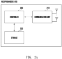
- FIG. 2A is a diagram illustrating an example of a configuration of a receiving device performing communications in a wireless communication system according to various embodiments of the disclosure.
- the receiving device 120 may include a communication unit 210, a storage 220, and a controller 230.
- the communication unit 210 may perform functions for transmitting and receiving signals over a wireless channel. For example, the communication unit 210 may perform a conversion function between a baseband signal and a bit stream according to a physical layer specification of the system. For example, when transmitting data, the communication unit 210 may encode and modulate a transmission bit stream to generate complex symbols. Further, upon receiving data, the communication unit 210 may demodulate and decode the baseband signal to reconstruct a received bit stream. In addition, the communication unit 210 may up-convert the baseband signal into a radio frequency (RF) band signal to transmit the RF band signal an the antenna, and down-convert the RF band signal received via the antenna into the baseband signal.
- RF radio frequency
- the communication unit 210 may include a transmission filter, a reception filter, an amplifier, a mixer, an oscillator, a digital-to-analog converter (DAC), an analog-to-digital converter (ADC), or the like. Further, the communication unit 210 may include a plurality of transmission/reception paths. Furthermore, the communication unit 210 may include at least one antenna array having a plurality of antenna elements. In terms of hardware, the communicator 210 may include a digital unit and an analog unit, in which the analog unit may include a plurality of sub-units depending on its operating power, operating frequency, and the like. Further, the communication unit 210 may include a decoding unit to perform decoding according to various embodiments of the disclosure.
- the communication unit 210 serves to transmit and receive signals as described above. Accordingly, the communication unit 210 may be referred to as a "transmitter”, a “receiver”, or a “transceiver”. Further, throughout the following description, transmission and reception performed over a wireless channel are used as meaning indicating that the above-described processing is performed by the communication unit 210.
- the communication unit 210 may further include a backhaul communication unit for communication with another network entity connected through a backhaul network.
- the storage 220 may store data such as a basic program, an application program, setting information and the like for operating the reception node 120.
- the storage 220 may include a volatile memory, a non-volatile memory, or a combination of the volatile memory and the non-volatile memory.
- the storage 220 may provide the stored data according to a request of the controller 230.
- the controller 230 may control the overall operations of the system. For example, the controller 230 may transmit and receive signals via the communication unit 210. Further, the controller 230 may record or read out data in the storage 220. To this end, the controller 230 may include at least one processor or a micro-processor, or may be a part of the processor. According to various embodiments, the controller 230 may control the system to perform operations according to various embodiments described below.
- FIG. 2B is a diagram illustrating an example of a configuration of a transmitting device performing communications in a wireless communication system according to various embodiments of the disclosure.
- the transmitting device 110 may include a communication unit 240, a storage 250, and a controller 260.
- the communication unit 240 may perform functions for transmitting and receiving signals over a wireless channel. For example, the communication unit 240 may perform a conversion function between a baseband signal and a bit stream according to the physical layer specification of the system. For example, during data transmission, the communication unit 240 may generate complex symbols by encoding and modulating a transmission bit stream. Further, when receiving data, the communication unit 240 may reconstruct the received bit stream by demodulating and decoding the baseband signal. In addition, the communication unit 240 may up-convert the baseband signal into a radio frequency (RF) band signal to transmit the RF band signal via an antenna, and down-convert the RF band signal received via the antenna into the baseband signal.
- RF radio frequency
- the communication unit 240 may include a transmission filter, a reception filter, an amplifier, a mixer, an oscillator, a digital-to-analog converter (DAC), an analog-to-digital converter (ADC), and the like.
- the communication unit 240 may include a plurality of transmission/reception paths.
- the communication unit 240 may include at least one antenna array having a plurality of antenna elements.
- the communicator 240 may include a digital unit and an analog unit, and the analog unit may include a plurality of sub-units depending on its operating power, its operating frequency, and the like.
- the communication unit 240 may include an encoding unit to perform encoding according to various embodiments of the disclosure.
- the communication unit 240 serve to transmit and receive signals as described above. Accordingly, the communication unit 240 may be referred to as a "transmitter”, a “receiver”, or a “transceiver”. In addition, throughout the following description, transmission and reception performed over a wireless channel are used as meaning to indicate that the above-described processing is performed by the communication unit 240. Further, when the device of FIG. 2B is a base station, the communication unit 240 may further include a backhaul communication unit for communication with another network entity connected through a backhaul network.
- the storage 250 may store data such as a basic program, an application program, setting information or the like for operating the transmission node 110.
- the storage 250 may include a volatile memory, a non-volatile memory, or a combination of the volatile memory and the non-volatile memory. Further, the storage 250 may provide the stored data according to a request of the controller 260.
- the controller 260 may control the overall operations of the system. For example, the controller 260 may transmit and receive a signal via the communication unit 240. Further, the controller 260 may record or read out data in the storage 250. To this end, the controller 260 may include at least one processor or a micro-processor, or may be a part of the processor. According to various embodiments, the controller 260 may control the system to perform operations according to various embodiments described below.
- the LDPC code is a linear code and is generally defined by a parity-check matrix.
- K the number of information bits (also referred to as a code dimension) to be encoded using the LDPC code
- code length the number of codeword bits (code length) resulting from encoding
- a value N - K obtained by subtracting the code dimension from the code length is referred to as the number of parity bits, the number of redundant bits.
- the information bit sequence of the length K to be encoded may be a codeword sequence encoded by outer coding such as a cyclic redundancy check (CRC) code or the like.
- outer coding such as a cyclic redundancy check (CRC) code or the like.
- the parity check matrix is given as H ⁇ F 2 N ⁇ K ⁇ N
- any codeword bit vector x of the LDPC code defined by the parity check matrix H is a null space for the parity check matrix H .
- the j -th row of H is denoted as h j ⁇ F 2 1 ⁇ N (row vector)
- the element of the j -th row of H and its i -th column is to be written as h ji ⁇ F 2 .
- the encoding and decoding of the LDPC code may be performed based on such a parity check matrix.
- the decoding of the LDPC code may be understood as a message-passing, so-called a belief-propagation process, in which messages are repeatedly exchanged on a binary graph corresponding to the parity check matrix.
- FIG. 3 is a diagram illustrating an embodiment of a parity check matrix of an LDPC code.
- the number of 1 in the parity check matrix is referred to as density, which density determines the complexity of encoding and decoding. Since the density of a general parity check matrix of the LDPC code is very low compared to the dimension of the entire parity check matrix, it is called a low-density parity check code.
- the parity check matrix in Figure 3 is of an example for an illustration purpose only and is a matrix of a very small dimension, so the density is relatively high, and the parity check matrix with a larger dimension commonly used may have much lower density.
- FIG. 4 is a diagram representing a binary graph corresponding to the parity check matrix of FIG. 3 .
- the binary graph may comprise a set of variable nodes v ( v
- N ), a set of check nodes (
- N - K ), and a set ( ⁇ ) of edges connecting elements of the two sets to each other.
- the variable nodes correspond to each bit of the codeword bit vector x ⁇ F 2 N , wherein the i -th variable node represents i -th second codeword bit having the same index.
- the check node represents a linear equation indicated by the inner product on a binary field of each row of the parity check matrix H and the codeword bit vector x .
- the belief-propagation decoding of the LDPC code may be understood as an iterative message exchange process using the relationship between the variable node and the check node on the graph.
- the LDPC code is being utilized in various communication and broadcasting systems, and is designed and used to satisfy the requirements demanded according to the characteristics of the systems.
- the requirements of channel codes for communication systems include length-flexibility of code length.
- the amount of communication resources such as time, frequency or the like available for transmission of specific information may change every transmission for various reasons. For example, the total amount of available communication resources may change, or the amount of communication resources allocated to transmit the corresponding information from the total available communication resources may change. Since the number of bits capable of transmission changes at every time point of transmission, the channel code used for the communication system should be designed to flexibly change its code length.
- channel quality between the transmitter and receiver varies over time. For example, when the receiver is physically moving, the distance between the transmitter and receiver may change, resulting in different channel conditions such as e.g., path loss and multi-path fading.
- the transmitter may increase the encoding rate (i.e., reduce the number of parity bits) to achieve error-free encryption/decryption with efficient utilization of communication resources.
- the transmitter may decrease the encoding rate (i.e., increase the number of parity bits) to increase the probability of overcoming the poor channel. Therefore, the channel coding used in communication systems should be designed to allow for flexible variation of the code rate.
- the transmitter encodes the information bit to be transmitted to create a codeword, and generates a signal through a processing such as modulation to transmit the signal to the receiver.
- the receiver attempts to decode the signal received from this first transmission (or initial transmission) by processing it through a series of processes. If the receiver detects an error through decoding of a CRC code and syndrome checking of an LDPC code, the receiver transmits the NACK to the transmitter to request retransmission.
- the receiver processes the received signal in a series of processes and then stores a log-likelihood ratio (LLR) sequence used for the decoding in a memory, a buffer, or the like.
- LLR log-likelihood ratio
- the LLR is given as a value obtained by taking a logarithm to the ratio of the probability for the values 0 and 1 of each bit, and is used as a probability information metric for the corresponding bit.
- the transmitter After receiving the NACK from the receiver, the transmitter generates a codeword for the existing information it wanted to transmit and transmits the codeword to the receiver. After the initial transmission, for example, the second transmission may be expressed as retransmission.
- the codeword generated for retransmission may be the same as the codeword transmitted in the initial transmission, and this HARQ scheme is referred to as Chase Combining HARQ (CC-HARQ).
- the codeword may be generated and transmitted to include parity bits that were not sent during initial transmission, which is referred to as an Incremental Redundancy HARQ (IR-HARQ) scheme.
- IR-HARQ Incremental Redundancy HARQ
- the receiver performs decoding by combining and utilizing the LLR sequence or the like stored in the initial transmission (although the decoding has failed) with the LLR sequence or the like newly obtained in the retransmission.
- the channel code for a communication system should be designed to allow decoding to be performed by combining two or more codewords generated to transmit the same information, that is, to have rate compatibility.
- the LDPC code for a practical communication system is designed to have the above required characteristics (flexible code length, flexible code rate, and rate compatibility).
- NR New Radio
- 5G 5th generation
- 3GPP 3rd Generation Partnership Project
- the LDPC code satisfying the aforementioned requirement characteristics is designed and in use.
- the LDPC code of the NR system will be described as an example of the target system of the disclosure.
- the disclosure is not limited to such a system, and may be also applied to other various systems.
- LDPC code systems actually used are designed with Quasi-Cyclic LDPC (QC-LDPC) codes that is suitable for implementation while satisfying the above required characteristic.
- the QC-LDPC codes belong to a structured LDPC coding class, and thus, they are widely used because they are easy to define the codes and are suitable for obtaining high throughput by decoding in a parallel architecture.
- the QC-LDPC codes are defined from a small base matrix or a base graph (BG) in a one-to-one correspondence relationship with the base matrix, as shown in FIGS. 3 and 4 .
- the base matrix and the base graph are treated as the same as each other.
- the base matrix may be written as H p ⁇ F 2 n ⁇ k ⁇ n , wherein the number of rows of the base matrix is n - k and the number of columns thereof is n .
- the parity check matrix H ⁇ F 2 N ⁇ K ⁇ N to be finally obtained may be obtained by increasing the size of the base matrix H p through a copy-and-permute process.
- the copy-and-permute process of the QC-LDPC code is referred to as lifting
- the size used to increase H p to construct the parity check matrix H is referred to as a lifting size.
- the lifting size is represented as Z.
- the size of the parity check matrix H is Z times the size of the base matrix H p .
- the lifting process may be understood to replace each element of the base matrix with a square matrix Z ⁇ Z .
- an exponential matrix E p ⁇ Z Z n ⁇ k ⁇ n is defined, which is another matrix of the same size as the base matrix.
- Each element of the base matrix is determined by its value and a value of the element at the same position as the exponential matrix.
- an element having a value of 0 is substituted with a zero matrix having a size of Z ⁇ Z (i.e., a matrix having a value of 0 for all elements).
- an element having a value of 1 is substituted with a circulant permutation matrix having the size of Z ⁇ Z , wherein the circulant permutation matrix is a matrix obtained by circularly shifting an identity matrix having the same size Z ⁇ Z by a value recorded at the same position in the exponential matrix.
- FIG. 5 is a diagram for use in understanding a lifting process, illustrating an example of a parity check matrix of a QC-LDPC code.
- a reference numeral 510 shown in FIG. 5 represents a parity check matrix H by displaying an exponential matrix E p on a base matrix H p . That is, the value described at each position of the matrix of 510 represents a circular shift value of each circulant permutation matrix indicated by the exponential matrix E p . Specifically, the portion where no value is indicated at each position is a portion where the element is 0 in the corresponding base matrix H p , and becomes Z ⁇ Z zero matrix as described above.
- the portion where a value is indicated at each position is Z ⁇ Z circulant permutation matrix, and its circular shift value is determined by the value indicated at each position.
- a reference numeral 511 is an element having a value of 2, and this portion actually represents Z ⁇ Z circulant permutation matrix 512 having a circular shift value of 2.
- the QC-LDPC code configured as described above adjusts the code dimension and length by adjusting the lifting size Z value.
- the code dimension and length of the base matrix H p are k and n, respectively.
- the parity check matrices of various code dimensions and lengths may be defined by adjusting the Z value based on these characteristics.
- the 3GPP NR LDPC code system defines two base graphs, BG1 and BG2, and lifts these two base graphs to various sizes to obtain a parity check matrix.
- BG1 is used to support a situation in which the code dimension and length are relatively large and the code rate is high
- BG2 is used to support situations in which the code dimension and length are relatively small and the code rate is low.
- the decoder of the QC-LDPC code may basically perform operations in Z-bit units.
- the decoding operation of the LDPC code is based on the parity check matrix H , and H is made up of circulant permutation matrices having the size of Z ⁇ Z , as described above.
- H is made up of circulant permutation matrices having the size of Z ⁇ Z , as described above.
- a circulant permutation matrix there is only one non-zero element in a particular row, and likewise, there is only one non-zero element in a particular column. Based on these characteristics, a variable node and a check node for each circulant permutation matrix may perform completely independent operations independently of each other without any conflict.
- the Z variable nodes and the Z check nodes making up the circulant permutation matrix may perform their operations independently of each other, and thus may be fully parallelized.
- the decoder for the QC-LDPC code is usually configured of the form to process each Z ⁇ Z circulant permutation matrix unit, or to process units of Z rows (i.e., submatrix of a size Z ⁇ N ) of the parity check matrix.
- a decoding scheduling scheme for sequentially processing units of Z rows i.e., submatrix of size Z ⁇ N
- Such a layered decoding scheme is widely used as a practical decoding scheme for decoding QC-LDPC codes.
- the transmitter generates a codeword bit sequence of length E suitable for a given transmission resource, from a codeword generated by a mother QC-LDPC code of code length N for each transmission.
- rate-matching this process of generating a codeword sequence by adjusting the code rate to be suitable for the transmission resource from the codeword of the mother code.
- This operation is usually carried out based on a virtual circular buffer and is referred to as circular-buffer rate-matching.
- the symbol N represents a length of the mother code used
- the symbol E represents the rate-matching output size transmitted and received.
- the rate-matching output length E is determined by the communication resource given for each transmission, and repetition of the codeword bit of the mother code occurs when E is greater than N, and puncturing of the codeword bit of the mother code occurs when E is less than N.
- the number of bits of the transmitted codeword i.e., the code length E
- the code dimension K should be greater than or equal to the code dimension K.
- the decoder may be unable to obtain any information about K-E non-transmitted information bits, and thus, it may be unable to perform normal decoding.
- the code length transmitted in i -th transmission is denoted by E i .
- E i the code length transmitted in i -th transmission.
- the condition of E 1 ⁇ K should be satisfied.
- the length of the entire code used by the decoder becomes E 1 + E 2
- the condition of E 1 + E 2 ⁇ K should be satisfied for the decoding to be successful.
- the condition of E 1 ⁇ K since the condition of E 1 ⁇ K has been already satisfied at the initial transmission, only the condition of E 2 ⁇ O needs to be satisfied for E 2 , and if the transmission has been already made, there may be no special restrictions for E 2 because it is at least E 2 >O.
- the code length becomes smaller after the retransmission, it is because the amount of communication resources allocated for the codeword transmission has been reduced compared to the initial transmission. In fact, the total amount of physical communication resources may have decreased, or although the total amount of communication resources may not have decreased, the amount of resources allocated for the corresponding codeword transmission may have decreased due to transmission of other information.
- E i ⁇ Z may be a critical problem in the decoder structure for the QC-LDPC code described above.
- the decoder of the QC-LDPC code may have a minimum operating unit of Z bits for an effective operation. Owing to the configuration of the consistent decoder as well as the decoding operation, its related peripheral operation may also be configured in Z-bit units.
- an embodiment of the disclosure proposes a method of identifying a condition related to a code length and a minimum operating unit, and readjusting an input LLR sequence according to a procedure based on the condition or generating a new input LLR sequence.
- an embodiment of the disclosure will be described in detail with reference to FIG. 6 .
- the decoder identifies a code parameter (code dimension K, mother code length N, transmission codeword length E, modulation order Q m ) for a codeword transmitted by the transmitter.
- the modulation order is a value determined by the modulation scheme in use, and it is 1 for the binary phase shift keying (BPSK), 2 for the quadrature phase shift keying (QPSK), and a value determined by log 2 M for the quadrature amplitude modulation (M-ary QAM).
- the decoder may configure or determine the parity check matrix of the QC-LDPC code to be used for decoding based on the identified code parameters.
- the decoder identifies a unit B operating the decoder, and this value in the decoder for the QC-LDPC code is usually related to the lifting size Z value. That is, the operating unit B of the decoder may be the same as Z or may be determined based on Z.
- A may be a minimum operating unit determined based on the characteristics of the decoder.
- the default operating unit B may be determined differently by the configuration of the decoder.
- the length E' of the modified LLR sequence may be simply determined as B, or may be determined to be greater than or equal to B depending on the configuration of the subsequent operation. For example, when the subsequent operation includes bit deinterleaving based on the modulation order Q m , the length E' of the modified LLR sequence may be determined to be a multiple of the modulation order Q m while being greater than or equal to the operating unit B.
- E' of the modified LLR sequence to be processed by the decoder is as small as possible, it may be determined, for example, using the following equation.
- E ′ ⁇ B / Q m ⁇ ⁇ Q m
- E' is a multiple of the smallest Q m that is greater than or equal to B.
- the modified LLR sequence ⁇ ' may be generated by appending E'-E LLR 0s after ⁇ of the length E.
- the decoder may perform the decoding based on the modified LLR sequence ⁇ ', assuming that the length of the input LLR sequence is E'.
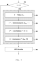
- FIG. 7 is a sequence diagram illustrating a process of performing decoding after a series of pre-processing according to an embodiment of the disclosure.
- the series of processes will be described by taking a bit interleaving operation performed in a 5G NR system as an example.
- the length E' of the modified LLR sequence may be determined using Equation 2 (720).
- the deinterleaving operation may be performed to obtain a result as described in the following pseudo-code.
- the interleaving operation may be performed to obtain a result as described in the following pseudo-code.
- the decoder may perform decoding based on the same.
- the lifting size Z determined by the code parameter of the initial transmission is 64
- the length E of the codeword transmitted in the retransmission is 36 bits.
- 64QAM was used as the modulation technique, and Q m is 6.
- the operating unit B was determined to be 64
- This deinterleaving operation may be also understood as a process of writing an LLR sequence in the allocated rectangular buffer by each column and reading the same by each row.
- the LLR index of the LLR sequence ⁇ written from each column in the rectangular buffer is given as shown in the table below. 0 6 12 18 24 30 1 7 13 19 25 31 2 8 14 20 26 32 3 9 15 21 27 33 4 10 16 22 28 34 5 11 17 23 29 35
- L 1 ⁇ 0 , ⁇ 6 , ⁇ 12 , ⁇ 18 , ⁇ 24 , ⁇ 30 , ⁇ 1 , ⁇ 7 , ⁇ 13 , ⁇ 19 , ⁇ 25 , ⁇ 31 , ... , ⁇ 5 , ⁇ 11 , ⁇ 17 , ⁇ 23 , ⁇ 29 , ⁇ 35
- L 2 ⁇ 0 , ⁇ 6 , ⁇ 12 , ⁇ 18 , ⁇ 24 , ⁇ 30 , ... , ⁇ 5 , ⁇ 11 , ⁇ 17 , ⁇ 23 , ⁇ 29 , ⁇ 35 , 0 , 0,0 , ... , 0
- This interleaving operation may be understood as a process of writing the LLR sequence in a given rectangular buffer from each row and reading the LLR sequence by each column.
- the index of the LLR in which the LLR sequence is written from each row in the rectangular buffer is given as shown in the table below, where -1 represents the position where the LLR 0 is mapped.
- the above buffer shape is also shown in FIG. 8 .
- the length E' of the finally modified LLR sequence may be determined by the operating unit B (which may be determined by the lifting size Z), the length E of the input LLR sequence, the modulation order Q m , or the like.
- the decoder may not determine the value of E' using Equation 2, but may use a predetermined constant that is always the same value.
- E' since E' should be a multiple of the modulation order Q m , it may be determined as a common multiple of all modulation orders used in the communication system to be applied.
- the modulation orders 1, 2, 4, 6, and 8 are considered in a 5G NR system, and thus, a multiple of 24, which is a least common multiple, may be fixed and used as E'.
- E' may be determined to be 384.
- E' may be determined as 480 in the same way. With this fixed value of E', the interleaving operation may be always performed consistently for the same length.
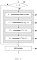
- FIG. 9 is a sequence diagram illustrating a process of performing a series of pre-processing and then decoding based on a predetermined length according to an embodiment of the disclosure.
- the decoder may determine the length E' of the modified LLR sequence with a preset value according to the foregoing (920).
- the decoder may perform decoding based on the modified LLR sequence.
- a similar problem may also occur in the encoder of the transmitter when the length of the sequence to be processed as in the decoder is less than the operating unit.
- the number of bits, E, transmitted by rate-matching of the encoder may be less than the operating unit B of the encoder, and the encoder may not perform a normal operation due to an explicit or implied reason.
- This problem may usually occur in an LDPC encoder having a hardware-fixed structure. This circumstance may generally occur after retransmission according to the HARQ operation.
- the operating unit B is denoted by the same symbol, but the operating unit of the decoder and the operating unit of the encoder described above may be the same as or different from each other.
- FIG. 10 is a diagram illustrating a process of performing encoding including post-processing according to conditions in an embodiment of the disclosure.
- the encoder may operate as shown in a block diagram of FIG. 10 in a situation where the number of bits, E, transmitted is less than the operating unit B of the encoder, as described above.
- the encoder having the constraint according to the operating length may not operate normally in case where a rate-matching output length E is less than the operating unit B.
- the encoder may determine the modified rate-matching output length E' to be greater than or equal to B and perform subsequent processes.
- E' should be determined as a multiple of Q m and may be determined as in Equation 2.
- it may always be determined as the same value regardless of the operating unit B, and for example, it may be determined as a common multiple (e.g. 384 or 480) of all modulation orders Q m used in the system.
- FIG. 11 is a diagram illustrating an example of a process of a post-processing operation according to an embodiment of the disclosure.
- a method for processing a signal encoded by LDPC coding, in an HARQ operation may comprise the steps of receiving a transmitted signal; identifying a code parameter applied by initial transmission of the HARQ operation and determining a configuration of a decoder; generating a first sequence of an LDPC code decoder of an LLR or the like from the received signal based on the configuration; comparing a length of the first sequence with an operating unit of the configured LDPC code decoder; when the length of the first sequence is less than the operating unit, generating a second sequence based on the first sequence; and decoding the LDPC code based on the second sequence.
- the length of the second sequence may be at least equal to or greater than the operating unit determined by the configuration of the LDPC code decoder.
- the operating unit determined by the configuration of the LDPC code decoder may be determined based on a lifting size of the decoder.
- the second sequence may be obtained by appending an element having a value of 0 to the first sequence.
- the second sequence may be obtained by performing first interleaving onto the first sequence, appending thereto the element having a value of 0, and performing second interleaving thereon.
- the first interleaving and the second interleaving are for sequences having different lengths, but their operations may be defined as an inverse relationship.
- the first interleaving and the second interleaving may be defined as deinterleaving and interleaving operations as described above, respectively.
- a computer-readable storage medium or a computer program product storing one or more programs (software modules) may be provided.
- the one or more programs stored in the computer-readable storage medium or the computer program product are configured for execution by one or more processors in an electronic device.
- the one or more programs include instructions that cause the electronic device to execute methods according to embodiments described in the specification or claims of the disclosure.
- These programs may be stored in a random access memory, a non-volatile memory including a flash memory, a read only memory (ROM), an electrically erasable programmable read only memory (EEPROM), a magnetic disc storage device, a compact disc ROM (CD-ROM), digital versatile discs (DVDs), other types of optical storage devices, magnetic cassettes, or the like.
- a non-volatile memory including a flash memory, a read only memory (ROM), an electrically erasable programmable read only memory (EEPROM), a magnetic disc storage device, a compact disc ROM (CD-ROM), digital versatile discs (DVDs), other types of optical storage devices, magnetic cassettes, or the like.
- ROM read only memory
- EEPROM electrically erasable programmable read only memory
- CD-ROM compact disc ROM
- DVDs digital versatile discs
- the program may be stored in an attachable storage device that is accessible via a communication network such as e.g., Internet, Intranet, a local area network (LAN), a wide LAN (WLAN), or a storage area network (SAN), or a communication network configured with a combination of those.
- a storage device may access a device performing an embodiment of the disclosure via an external port.
- a separate storage device on a communication network may access the device performing embodiments of the disclosure.
- an element included in the disclosure is expressed in a singular or plural form depending on a presented specific embodiment.
- the singular form or plural form is selected to suit its presented situation for the convenience of description, and the disclosure is not limited to the singular element or the plural element presented, and either a component expressed in plural may be configured in a singular form, or a component expressed in singular may be configured in a plural form.
- the embodiments of the disclosure disclosed in the specification and drawings are merely certain examples presented to easily describe the technical contents of the disclosure and help understanding of the disclosure, and are not intended to limit the scope of the disclosure thereto. That is, it is obvious to those skilled in the art to which the disclosure pertains that other modified examples based on the technical idea of the disclosure may be implemented.
- Each of the embodiments may be operated in combination with each other as necessary.
- a base station and a terminal may be operated by combining parts of an embodiment of the disclosure and parts of another embodiment of the disclosure.
- the embodiments of the disclosure may also be applied to other communication systems, and other modifications based on the technical idea of the embodiments may also be implemented.
- the embodiments may also be applied to an LTE system, a 5G system, or an NR system.
Landscapes
- Engineering & Computer Science (AREA)
- Physics & Mathematics (AREA)
- Computer Networks & Wireless Communication (AREA)
- Signal Processing (AREA)
- Probability & Statistics with Applications (AREA)
- Theoretical Computer Science (AREA)
- Mathematical Physics (AREA)
- Computer Security & Cryptography (AREA)
- Quality & Reliability (AREA)
- Error Detection And Correction (AREA)
- Mobile Radio Communication Systems (AREA)
Applications Claiming Priority (2)
| Application Number | Priority Date | Filing Date | Title |
|---|---|---|---|
| KR1020210120393A KR20230037264A (ko) | 2021-09-09 | 2021-09-09 | 통신 시스템에서 신호 송수신 방법 및 장치 |
| PCT/KR2022/011761 WO2023038304A1 (ko) | 2021-09-09 | 2022-08-08 | 통신 시스템에서 신호 송수신 방법 및 장치 |
Publications (2)
| Publication Number | Publication Date |
|---|---|
| EP4383604A1 true EP4383604A1 (de) | 2024-06-12 |
| EP4383604A4 EP4383604A4 (de) | 2024-12-04 |
Family
ID=85506710
Family Applications (1)
| Application Number | Title | Priority Date | Filing Date |
|---|---|---|---|
| EP22867573.2A Pending EP4383604A4 (de) | 2021-09-09 | 2022-08-08 | Verfahren und vorrichtung zum senden oder empfangen eines signals in einem kommunikationssystem |
Country Status (4)
| Country | Link |
|---|---|
| US (1) | US20240214322A1 (de) |
| EP (1) | EP4383604A4 (de) |
| KR (1) | KR20230037264A (de) |
| WO (1) | WO2023038304A1 (de) |
Families Citing this family (1)
| Publication number | Priority date | Publication date | Assignee | Title |
|---|---|---|---|---|
| KR20250093871A (ko) * | 2023-12-18 | 2025-06-25 | 삼성전자주식회사 | 무선 통신 및 방송 시스템에서 채널 부호의 앙상블 복호 방법 및 장치 |
Family Cites Families (7)
| Publication number | Priority date | Publication date | Assignee | Title |
|---|---|---|---|---|
| KR101102396B1 (ko) * | 2006-02-08 | 2012-01-05 | 엘지전자 주식회사 | 이동통신 시스템에서의 코드워드 크기 정합 방법 및 송신장치 |
| US10804933B2 (en) * | 2016-09-30 | 2020-10-13 | Lg Electronics Inc. | QC LDPC code rate matching method and device therefor |
| KR102302366B1 (ko) * | 2017-05-04 | 2021-09-16 | 삼성전자 주식회사 | 통신 또는 방송 시스템에서 채널 부호화/복호화 방법 및 장치 |
| CN110583023B (zh) * | 2017-05-04 | 2022-03-01 | 三星电子株式会社 | 在通信或广播系统中用于信道编码和解码的方法和设备 |
| KR102378324B1 (ko) * | 2017-06-19 | 2022-03-25 | 삼성전자 주식회사 | 통신 및 방송 시스템을 위한 부호율-조정 방법 및 장치 |
| CN118487610A (zh) * | 2017-06-27 | 2024-08-13 | 华为技术有限公司 | 信息处理的方法、装置和通信设备 |
| KR102450664B1 (ko) * | 2017-09-11 | 2022-10-04 | 지티이 코포레이션 | Ldpc 코딩된 데이터를 프로세싱하기 위한 방법 및 장치 |
-
2021
- 2021-09-09 KR KR1020210120393A patent/KR20230037264A/ko active Pending
-
2022
- 2022-08-08 WO PCT/KR2022/011761 patent/WO2023038304A1/ko not_active Ceased
- 2022-08-08 EP EP22867573.2A patent/EP4383604A4/de active Pending
-
2024
- 2024-03-07 US US18/598,425 patent/US20240214322A1/en active Pending
Also Published As
| Publication number | Publication date |
|---|---|
| WO2023038304A1 (ko) | 2023-03-16 |
| US20240214322A1 (en) | 2024-06-27 |
| KR20230037264A (ko) | 2023-03-16 |
| EP4383604A4 (de) | 2024-12-04 |
Similar Documents
| Publication | Publication Date | Title |
|---|---|---|
| US11838125B2 (en) | Apparatus and method for encoding and decoding using polar code in wireless communication system | |
| US12068851B2 (en) | Apparatus and method of transmission using HARQ in communication or broadcasting system | |
| US11451243B2 (en) | Method and apparatus for decoding data in communication or broadcasting system | |
| EP3954072B1 (de) | Verfahren und vorrichtungen zur datenübertragung in einem drahtloskommunikationssystem | |
| US11637653B2 (en) | Method and apparatus of rate-matching for communication and broadcasting systems | |
| US10742350B2 (en) | Method and apparatus of rate-matching for communication and broadcasting systems | |
| US11876534B2 (en) | Method and apparatus for data decoding in communication or broadcasting system | |
| US12170528B2 (en) | Method and apparatus for data decoding in communication or broadcasting system | |
| JP2024029096A (ja) | Ldpcコード化データを処理する方法および装置 | |
| WO2018059588A1 (zh) | 准循环ldpc编译码方法、装置及ldpc编译码器 | |
| KR20180107692A (ko) | 통신 또는 방송 시스템에서 harq 적용시 전송 방법 및 장치 | |
| US20240214322A1 (en) | Method and device for transmitting or receiving signal in communication system | |
| KR20200130063A (ko) | 무선 통신 시스템에서 데이터 전송 방법 및 장치 | |
| KR20180107703A (ko) | 통신 또는 방송 시스템에서 harq 적용시 전송 방법 및 장치 | |
| KR102930455B1 (ko) | 통신 및 방송 시스템에서 데이터 복호화 방법 및 장치 | |
| KR20240124150A (ko) | 무선 통신 시스템에서 수신된 신호를 처리하기 위한 전자 장치 및 방법 | |
| KR20180107701A (ko) | 통신 또는 방송 시스템에서 harq 적용시 전송 방법 및 장치 |
Legal Events
| Date | Code | Title | Description |
|---|---|---|---|
| STAA | Information on the status of an ep patent application or granted ep patent |
Free format text: STATUS: THE INTERNATIONAL PUBLICATION HAS BEEN MADE |
|
| PUAI | Public reference made under article 153(3) epc to a published international application that has entered the european phase |
Free format text: ORIGINAL CODE: 0009012 |
|
| STAA | Information on the status of an ep patent application or granted ep patent |
Free format text: STATUS: REQUEST FOR EXAMINATION WAS MADE |
|
| 17P | Request for examination filed |
Effective date: 20240307 |
|
| AK | Designated contracting states |
Kind code of ref document: A1 Designated state(s): AL AT BE BG CH CY CZ DE DK EE ES FI FR GB GR HR HU IE IS IT LI LT LU LV MC MK MT NL NO PL PT RO RS SE SI SK SM TR |
|
| A4 | Supplementary search report drawn up and despatched |
Effective date: 20241107 |
|
| RIC1 | Information provided on ipc code assigned before grant |
Ipc: H04L 47/36 20220101ALI20241031BHEP Ipc: H04L 47/34 20220101ALI20241031BHEP Ipc: H04L 1/00 20060101AFI20241031BHEP |
|
| DAV | Request for validation of the european patent (deleted) | ||
| DAX | Request for extension of the european patent (deleted) |