EP4383442A1 - Welding jig - Google Patents
Welding jig Download PDFInfo
- Publication number
- EP4383442A1 EP4383442A1 EP22911937.5A EP22911937A EP4383442A1 EP 4383442 A1 EP4383442 A1 EP 4383442A1 EP 22911937 A EP22911937 A EP 22911937A EP 4383442 A1 EP4383442 A1 EP 4383442A1
- Authority
- EP
- European Patent Office
- Prior art keywords
- welding
- jig
- protrusion
- secondary battery
- hole
- Prior art date
- Legal status (The legal status is an assumption and is not a legal conclusion. Google has not performed a legal analysis and makes no representation as to the accuracy of the status listed.)
- Granted
Links
Images


Classifications
-
- B—PERFORMING OPERATIONS; TRANSPORTING
- B23—MACHINE TOOLS; METAL-WORKING NOT OTHERWISE PROVIDED FOR
- B23K—SOLDERING OR UNSOLDERING; WELDING; CLADDING OR PLATING BY SOLDERING OR WELDING; CUTTING BY APPLYING HEAT LOCALLY, e.g. FLAME CUTTING; WORKING BY LASER BEAM
- B23K37/00—Auxiliary devices or processes, not specially adapted for a procedure covered by only one of the other main groups of this subclass
- B23K37/04—Auxiliary devices or processes, not specially adapted for a procedure covered by only one of the other main groups of this subclass for holding or positioning work
- B23K37/0426—Fixtures for other work
-
- B—PERFORMING OPERATIONS; TRANSPORTING
- B23—MACHINE TOOLS; METAL-WORKING NOT OTHERWISE PROVIDED FOR
- B23K—SOLDERING OR UNSOLDERING; WELDING; CLADDING OR PLATING BY SOLDERING OR WELDING; CUTTING BY APPLYING HEAT LOCALLY, e.g. FLAME CUTTING; WORKING BY LASER BEAM
- B23K26/00—Working by laser beam, e.g. welding, cutting or boring
- B23K26/14—Working by laser beam, e.g. welding, cutting or boring using a fluid stream, e.g. a jet of gas, in conjunction with the laser beam; Nozzles therefor
-
- B—PERFORMING OPERATIONS; TRANSPORTING
- B23—MACHINE TOOLS; METAL-WORKING NOT OTHERWISE PROVIDED FOR
- B23K—SOLDERING OR UNSOLDERING; WELDING; CLADDING OR PLATING BY SOLDERING OR WELDING; CUTTING BY APPLYING HEAT LOCALLY, e.g. FLAME CUTTING; WORKING BY LASER BEAM
- B23K37/00—Auxiliary devices or processes, not specially adapted for a procedure covered by only one of the other main groups of this subclass
- B23K37/04—Auxiliary devices or processes, not specially adapted for a procedure covered by only one of the other main groups of this subclass for holding or positioning work
- B23K37/0426—Fixtures for other work
- B23K37/0435—Clamps
- B23K37/0443—Jigs
-
- H—ELECTRICITY
- H01—ELECTRIC ELEMENTS
- H01M—PROCESSES OR MEANS, e.g. BATTERIES, FOR THE DIRECT CONVERSION OF CHEMICAL ENERGY INTO ELECTRICAL ENERGY
- H01M50/00—Constructional details or processes of manufacture of the non-active parts of electrochemical cells other than fuel cells, e.g. hybrid cells
- H01M50/10—Primary casings; Jackets or wrappings
- H01M50/102—Primary casings; Jackets or wrappings characterised by their shape or physical structure
- H01M50/107—Primary casings; Jackets or wrappings characterised by their shape or physical structure having curved cross-section, e.g. round or elliptic
-
- H—ELECTRICITY
- H01—ELECTRIC ELEMENTS
- H01M—PROCESSES OR MEANS, e.g. BATTERIES, FOR THE DIRECT CONVERSION OF CHEMICAL ENERGY INTO ELECTRICAL ENERGY
- H01M50/00—Constructional details or processes of manufacture of the non-active parts of electrochemical cells other than fuel cells, e.g. hybrid cells
- H01M50/50—Current conducting connections for cells or batteries
- H01M50/531—Electrode connections inside a battery casing
- H01M50/536—Electrode connections inside a battery casing characterised by the method of fixing the leads to the electrodes, e.g. by welding
-
- B—PERFORMING OPERATIONS; TRANSPORTING
- B23—MACHINE TOOLS; METAL-WORKING NOT OTHERWISE PROVIDED FOR
- B23K—SOLDERING OR UNSOLDERING; WELDING; CLADDING OR PLATING BY SOLDERING OR WELDING; CUTTING BY APPLYING HEAT LOCALLY, e.g. FLAME CUTTING; WORKING BY LASER BEAM
- B23K26/00—Working by laser beam, e.g. welding, cutting or boring
- B23K26/20—Bonding
- B23K26/21—Bonding by welding
-
- Y—GENERAL TAGGING OF NEW TECHNOLOGICAL DEVELOPMENTS; GENERAL TAGGING OF CROSS-SECTIONAL TECHNOLOGIES SPANNING OVER SEVERAL SECTIONS OF THE IPC; TECHNICAL SUBJECTS COVERED BY FORMER USPC CROSS-REFERENCE ART COLLECTIONS [XRACs] AND DIGESTS
- Y02—TECHNOLOGIES OR APPLICATIONS FOR MITIGATION OR ADAPTATION AGAINST CLIMATE CHANGE
- Y02E—REDUCTION OF GREENHOUSE GAS [GHG] EMISSIONS, RELATED TO ENERGY GENERATION, TRANSMISSION OR DISTRIBUTION
- Y02E60/00—Enabling technologies; Technologies with a potential or indirect contribution to GHG emissions mitigation
- Y02E60/10—Energy storage using batteries
Definitions
- the present invention relates to a jig for welding, and more particularly, to a jig for welding that is capable of preventing spatter, which is foreign matter caused by welding, from being introduced into a secondary battery during welding between a collector plate connected to an electrode assembly in a secondary battery can body and a beading part that is a portion recessed inward from the can body, and is capable of improving quality of the welding by increasing a welding force between the collector plate and the beading part, which are objects to be welded, to increase a degree of completion of the welding.
- secondary batteries may be classified into a cylindrical type battery and a prismatic type battery, each of which has an electrode assembly embedded in a cylindrical or prismatic metal can, a pouch type battery having an electrode assembly embedded in a pouch type case made of an aluminum laminate sheet, and so on.
- the electrode assembly embedded in a battery case is a chargeable and dischargeable power generation element having a structure in which a positive electrode/a separator/a negative electrode are stacked.
- the electrode assembly may be classified into an electrode assembly having a jelly-roll-type structure in which long sheet-shaped positive and negative electrodes, each of which is coated with an active material, are wound by interposing a separator therebetween, an electrode assembly having a stacked type structure in which multiple positive and negative electrodes, each of which has a predetermined size, are stacked in sequence with a separator interposed therebetween, and a stack and folding type electrode assembly in a structure in which bi-cells or full-cells are wound which have positive and negative electrodes in a predetermined unit stacked with a separator interposed therebetween.
- the jelly-roll-type electrode assembly has advantages such as easiness in manufacture and a high energy density per weight, and thus, are widely manufactured.
- the jelly-roll-type electrode assembly may be manufactured by assembling a stack of the long sheet-shaped positive and negative electrodes and the separator interposed therebetween, and winding the electrode stack in a longitudinal direction of the sheet in a state in which a core is in contact with an end at one side of the electrode stack. Then, this jelly-roll-type electrode assembly may be inserted into a battery case provided in a cylindrical metal can to form a cylindrical type secondary battery.
- Such a cylindrical type secondary battery is designed to have a high energy density and thus, a demand for the cylindrical type secondary battery is also on an increasing trend.
- a new sized cell (a tabless cell) manufactured to be in a tabless state is a secondary battery that has an energy density 5 times higher than that of the existing one and thus, has high investment cost efficiency.
- the present invention has been devised to solve the problems as above and an object of the present invention is to provide to a jig for welding that is capable of preventing spatter, which is foreign matter caused by welding, from being introduced into a secondary battery during welding between a collector plate connected to an electrode assembly in a secondary battery can body and a beading part that is a portion recessed inward from the can body, and is capable of improving quality of the welding by increasing a welding force between the collector plate and the beading part, which are objects to be welded, to increase a degree of completion of the welding.
- a jig for welding relates to a jig for welding that is used in a welding process during manufacturing of a secondary battery, and includes a body part, and a protrusion that extends downward from a bottom surface of the body part, has a size corresponding to a top opening of the secondary battery, and is inserted into the top opening of the secondary battery in the welding process, wherein a welding hole through which laser that performs the welding passes is defined in each of a circumferential portion of the protrusion and a region of the body part, which corresponds to a circumferential portion of the protrusion, wherein the protrusion includes a pressing portion that is provided in a peripheral part of the welding hole and presses an object to be welded in the secondary battery.
- a size of an outlet through which the laser is discharged may be smaller than a size of an inlet through which the laser enters.
- the welding hole may have a shape in which a width gradually decreases in a downward direction.
- a pair of welding holes may be provided in each of positions at which a circumferential portion of the protrusion is quartered at an angle of 90 degree to form a total of eight through-holes.
- the welding hole may be provided in each of positions at which a circumferential portion of the protrusion is quartered at an angle of 90 degree to form a total of four through-holes.
- the pressing portion may be a portion of a bottom surface of the protrusion, which presses the object to be welded.
- the protrusion may include a shielding gas inlet nozzle that is provided in an inner side of the circumferential portion and to allow shielding gas to flow into the secondary battery.
- a shielding gas flow hole for supplying, to the welding hole, the shielding gas flowing into the secondary battery may be defined in a lower portion of the protrusion.
- the shielding gas flow hole may be defined to be communicated with a lower end of the welding hole.
- the shielding gas inlet nozzle may have a lower end that is disposed downward from the lower end of the welding hole by a predetermined distance.
- a shielding gas supply pipe for supplying the shielding gas to the shielding gas inlet nozzle may be connected to a side surface of the body part.
- the body part may include an edge part that is a region other than a region in which the protrusion is defined, and a coupling hole for fixing may be defined in the edge part.
- the pressing portion may be a pressing protrusion that is provided on a bottom surface of the protrusion and presses the object to be welded.
- the pressing protrusion may be provided to be adjacent to one side or the other side of the welding hole in a circumferential direction of the protrusion.
- the secondary battery may be a cylindrical type secondary battery, and the protrusion may be provided in a cylindrical shape and extend downward from the bottom surface of the body part.
- the pressing portion may press a top surface of a collector plate connected to an electrode assembly in the cylindrical type secondary battery in order to perform welding between the collector plate and a beading part that is provided in a cylindrical type secondary battery can body.
- the present invention relates to the jig for welding that is capable of preventing spatter, which is the foreign matter caused by the welding, from being introduced into the secondary battery during the welding between the collector plate connected to the electrode assembly in the secondary battery can body and the beading part that is the portion recessed inward from the can body, and is capable of improving the quality of the welding by increasing the welding force between the collector plate and the beading part, which are the objects to be welded, to increase the degree of completion of the welding.
- FIG. 1 is a perspective view illustrating a jig for welding according to Embodiment 1 of the present invention.
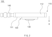
- FIG. 2 is a front view illustrating a jig for welding according to Embodiment 1 of the present invention.
- FIG. 3 is a plan view illustrating a jig for welding according to Embodiment 1 of the present invention.
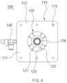
- FIG. 4 is a bottom view illustrating a jig for welding according to Embodiment 1 of the present invention.
- FIG. 5(a) is a cross-sectional view illustrating an electrode assembly and a collector plate connected to the electrode assembly.
- FIG. 5(b) is a plan view illustrating an object in FIG. 5(a) when viewed from an upper side.
- FIG. 5(a) is a cross-sectional view illustrating an electrode assembly and a collector plate connected to the electrode assembly.
- FIG. 5(b) is a plan view illustrating an object in FIG. 5(a) when viewed from an upper side.
- FIG. 6(a) is a cross-sectional view illustrating a state in which an electrode assembly to which a collector plate is connected is inserted into a secondary battery can body.
- FIG. 6(b) is a plan view illustrating an object in FIG. 5(a) when viewed from an upper side.
- FIG. 7 is a cross-sectional view illustrating a state in which a jig for welding according to Embodiment 1 of the present invention is used during manufacturing of a secondary battery.
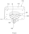
- FIG. 8 is a perspective view illustrating only a jig for welding and a collector plate according to Embodiment 1 of the present invention.
- a jig 100 for welding according to Embodiment 1 of the present invention may be the jig 100 for welding that is used in a welding process during manufacturing of a secondary battery.
- the jig 100 for welding according to Embodiment 1 of the present invention may include a body part 110 and a protrusion 120.
- the body part 110 may be a portion that constitutes a body of the jig 100 for welding.
- the protrusion 120 may be a portion that extends from a bottom surface 111 of the body part in a downward direction D.
- the protrusion 120 may be a portion that is inserted into an opening of the secondary battery in the welding process, and accordingly, the protrusion 120 may have a size corresponding to a top opening of the secondary battery.
- having a corresponding size may mean that, when the secondary battery is a cylindrical type, an opening diameter of the secondary battery and a diameter of the protrusion 120 correspond to each other.
- the protrusion 120 may be provided in a cylindrical shape and extend from the bottom surface 111 of the body part in the downward direction.
- shapes other than a circular shape it may mean that the shapes, widths, or the like, are provided to correspond to each other so as to be insertable.
- a welding hole 121 through which laser that performs the welding passes may be defined in each of a circumferential portion of the protrusion 120 and a region of the body part 110, which corresponds to the circumferential portion of the protrusion 120. That is, the welding hole 121 may be defined in the circumferential portion of the protrusion 120, and the welding hole 121 may be defined also in the body part 110 so as to communicated with the welding hole 121 defined in the circumferential portion of the protrusion 120.
- the laser that performs the welding needs to pass through the body part 110 and the protrusion 120, and a path through which this laser passes may be the welding hole 121.
- a pair welding holes 121 may be provided in each of positions at which a circumferential portion of the protrusion 120 is quartered at an angle of 90 degree to form a total of eight through-holes.
- the protrusion 120 may include a pressing portion 122 that is provided in a peripheral part of the welding hole 121 and presses an object to be welded in the secondary battery.
- the pressing portion 122 may be a portion of a bottom surface of the protrusion 120, which presses the object to be welded. That is, two objects to be welded to each other need to be pressed so as to be in close contact with each other during performing laser welding while the laser passes through the welding hole 121 and is emitted onto the objects to be welded. To this end, a component that presses the objects to be welded may be necessary. As a result, as necessary, the pressing portion 122 may be a portion that presses the objects to be welded. Thus, the pressing portion 122 may be a portion that is disposed around the welding hole 121 on the bottom surface of the protrusion 120.
- the pressing portion 122 may be a pressing surface that is provided in a planar shape, but is not necessarily limited to the planar shape. As reviewed in Embodiment 2 below, the pressing portion 122 may be provided in a shape of a protrusion. In addition, the pressing portion 122 may have any shape as long as the pressing is carried out effectively and efficiently through the shape.
- FIGS. 5 and 6 illustrate views of a cylindrical type secondary battery 1 to which the jig 100 for welding according to Embodiment 1 of the present invention is applicable.
- FIGS. 5 and 6 illustrate a portion of a welding process in manufacturing of a new sized cell (tabless cell) manufactured to be in a tabless state.
- FIG. 5 illustrates a state in which a collector plate 30 is connected to a jelly-roll-type electrode assembly 10 inserted into the new sized cell (tabless cell) by welding.
- the collector plate 30 may be a component that is a raw material welded to the jelly-roll-type electrode assembly 10 and serves to collect electrons.
- a combination of the electrode assembly 10 and the collector plate 30, which is illustrated in FIG. 5 may be inserted into a can body 20 illustrated in FIG. 6 .
- a beading part 21, which is provided to be recessed inwardly, may be provided in an upper portion of the can body 20 after the combination of the electrode assembly 10 and the collector plate 30 is inserted into the can body 20. Accordingly, an edge part of the collector plate 30 may be disposed on a top surface of the beading part 21.
- the welding between the beading part 21, which is provided to be recessed from an upper portion of the can, and the collector plate 30 may be performed.
- the jig 100 for welding according to Embodiment 1 of the present invention may be, as an example, a jig used in the welding between the beading part 21 and the collector plate 30.
- FIG. 7 illustrates a state, in which the protrusion 120 extending from a bottom surface 111 of the body part 110 in the downward direction D is inserted into a top opening of the secondary battery 1, and illustrates a state in which the jig 100 for welding according to Embodiment 1 of the present invention performs the welding while pressing a top surface of the collector plate 30, which is disposed on the top surface of the beading part 21.
- the pressing portion 122 may press the top surface of the collector plate 30 in order to perform the welding between the collector plate 30, which is connected to the electrode assembly 10 in the cylindrical type secondary battery 1, and the beading part 21 which is provided in the can body 20 of the cylindrical type secondary battery 1.
- the pressing portion 122 may increase a degree of completion of the welding by increasing a welding force between the collector plate 30 and the beading part 21, which are the objects to be welded.
- FIG. 8 is a view illustrating the jig 100 for welding and the collector plate 30 in order to clearly illustrate the state in which the jig 100 for welding according to Embodiment 1 of the present invention presses the collector plate 30.
- FIGS. 6 and 8 illustrate a welding position W, and this welding position W may be a position at which the laser passing through the welding hole 121 performs the welding.
- a pair of welding positions W may be provided in each of positions at which a circumferential portion of the collector plate 30 is quartered at an angle of 90 degree to form a total of eight welding positions. This may have a shape corresponding to the position of the welding hole 121.
- the welding hole 121 provided to pass through the protrusion 120 and the body part 110 may have a shape in which a size of an outlet through which the laser is discharged is smaller than a size of an inlet through which the laser enters.
- the welding hole 121 may have a shape in which a width gradually decreases in the downward direction.
- the welding hole 121 may have a small width in order not to allow the laser to be in contact with another point.
- An upper end of the welding hole 121 may has a great width in order to receive the laser having a greater width.
- the welding hole 121 may have a shape of which a width is great at an upper side and gradually decreases in the downward direction.
- the welding hole 121 may be provided in a shape in which a truncated cone is upside down. In addition, as illustrated in FIG.
- the welding hole 121 may be provided so that in the welding hole 121, an outer side surface is vertically inclined, and an inner side surface is gently inclined.
- the welding hole is not necessarily to have a shape of which the width gradually decreases, and there may be various possible embodiments in a shape in which the outlet is smaller than the inlet.
- the protrusion 120 may include a shielding gas inlet nozzle 130 that is provided in an inner side of the circumferential portion and to allow shielding gas to flow into the secondary battery 1.
- the shielding gas may mean inert or semiinert gas that is commonly used in the welding process.
- the shielding gas may serve to block introduction of oxygen in the atmosphere during high temperature reaction of the objects to be welded.
- the shielding gas may be nitrogen gas.
- the shielding gas may be supplied from the outside of the body part 110, and a shielding gas supply pipe 140 for supplying the shielding gas to the shielding gas inlet nozzle 130 may be connected to a side surface of the body part 110. That is, the shielding gas may flow from the outside of the body part 110 through the shielding gas supply pipe 140 into the body part 110 and then, flow into the secondary battery 1 through the shielding gas inlet nozzle 130.
- the shielding gas may flow into the can body 20 through the shielding gas inlet nozzle 130.
- the shielding gas has to form the atmosphere at a portion W at which the welding is performed, and thus, needs to flow to the portion at which the welding is performed.
- a shielding gas flow hole 123 may be defined in a lower portion of the protrusion 120.
- the shielding gas flow hole 123 may be a component that is defined in the lower portion of the protrusion 120 and provided to supply the shielding gas flowing into the secondary battery 1 to the welding hole 121.
- the shielding gas flow hole 123 may be provided to be communicated with a lower end of the welding hole 121, and the shielding gas may be supplied directly to a welding part (see an arrow G in FIG. 7 ). Thereafter, the shielding gas supplied thus to the welding part may flow upward through the welding hole 121 and be discharged to the outside (see an arrow F in FIG. 7 ).
- the jig 100 for welding according to Embodiment 1 of the present invention has a structure which shields all portions except for a laser irradiation portion for welding between the collector plate 30 and the beading part 21 and a shielding gas insertion part for forming the atmosphere during the welding, spatter that is foreign matter caused by the welding may be prevented from being introduced into the secondary battery 1.
- the shielding gas inlet nozzle 130 may have a lower end that is disposed downward from the lower end of the welding hole 121 by a predetermined distance. This structure may further prevent the spatter, which is foreign matter caused by the welding, from being introduced into the secondary battery 1, and may serve to allow the shielding gas to smoothly flow.
- the body part 110 may include an edge part 112 that is a region other than a region in which the protrusion 120 is defined.
- a coupling hole 113 for fixing may be defined in the edge part 112.
- the body part 110 or the protrusion 120 has not to be shaken for stable welding in the welding process and thus, may be fixed to a fixing device through the coupling hole 113 so as to perform a stable welding work.
- a total of six coupling holes 113 may be provided, i.e., three coupling holes 113 may be provided in one side, and three coupling holes may be provided in the other side.
- FIG. 9 is a front view illustrating a jig for welding according to Embodiment 2 of the present invention.
- FIG. 10 is a bottom view illustrating a jig for welding according to Embodiment 2 of the present invention.
- FIG. 11 is a plan view illustrating a portion of a collector plate, which is pressed by a jig for welding according to Embodiment 2 of the present invention.
- Embodiment 2 of the present invention is different from Embodiment 1 in that, in the jig 100 for welding according to Embodiment 1 of the present invention, the protrusion 120 includes a pressing protrusion 250.
- Embodiment 1 The content in common with Embodiment 1 will be preferably omitted and the description of Embodiment 2 will be focused on characteristics of a manufacturing method. That is, it is apparent that the content that is not described in Embodiment 2 may be regarded as the content of Embodiment 1 if necessary.
- a jig 200 for welding relates to the jig 200 for welding, which is used in a welding process during manufacturing of a secondary battery, and includes a body part 110, and a protrusion 120 that extends from a bottom surface 111 of the body part in a downward direction, has a size corresponding to a top opening of the secondary battery, and is inserted into the top opening of the secondary battery in the welding process.
- a welding hole 121 through which laser that performs the welding passes is defined in each of a circumferential portion of the protrusion 120 and a region of the body part 110, which corresponds to the circumferential portion of the protrusion 120.
- the protrusion 120 includes a pressing portion 122 that is provided in a peripheral part of the welding hole 121 and presses an object to be welded in the secondary battery 1.
- the pressing portion 122 may be the pressing protrusion 250 that is provided on a bottom surface of the protrusion 120 and presses the object to be welded.
- the pressing protrusion 250 may be a portion that is provided so as to further protrude from the bottom surface of the protrusion 120, which is adjacent to the welding hole 121, in a downward direction D.
- FIG. 10 illustrates an enlarged view of the pressing protrusion 250.
- the pressing protrusion 250 may be provided to be adjacent to one side or the other side of the welding hole 121 based on a circumferential direction of the protrusion 120. Accordingly, the pressing protrusion 250 may perform the pressing so as to be adjacent to one side or the other side of a welding position W at which the welding is performed (see FIG. 11 ).
- the pressing protrusion 250 of the protrusion 120 may be a component that enables point contact, not surface contact, when pressing objects to be welded.
- this pressing protrusion 250 may improve quality of the welding by increasing a welding force between a collector plate 30 and a beading part 21, which are the objects to be welded, to increase a degree of completion of the welding.
- FIG. 11 illustrates a position pressed by the pressing protrusion 250 on a top surface of the collector plate 30.
- a pair pressing protrusions 250 may be provided in each of positions at which a circumferential portion of the collector plate 30 is quartered at an angle of 90 degree. In this case, a total of eight pressing protrusions 250 may be provided.
- FIG. 12 is a plan view illustrating a jig for welding according to Embodiment 3 of the present invention.
- FIG. 13 is a bottom view illustrating a jig for welding according to Embodiment 3 of the present inventions.
- Embodiment 3 of the present invention is different from Embodiment 1 in that, in the jig 100 for welding according to Embodiment 1 of the present invention, the configuration such as the number of welding hole, is different.
- Embodiment 3 The content in common with Embodiment 1 will be preferably omitted and the description of Embodiment 3 will be focused on characteristics of the welding hole. That is, it is apparent that the content that is not described in Embodiment 3 may be regarded as the content of Embodiment 1 if necessary.
- a welding hole 321 through which laser that performs the welding passes may be defined in each of a circumferential portion of a protrusion 120 and a region of a body part 110, which corresponds to the circumferential portion of the protrusion 120. That is, the welding hole 321 may be defined in the circumferential portion of the protrusion 120, and the welding hole 321 may be defined also in the body part 110 so as to communicated with the welding hole 321 defined in the circumferential portion of the protrusion 120.
- the laser that performs the welding needs to pass through the body part 110 and the protrusion 120, and a path through which this laser passes may be the welding hole 321.
- the welding holes 321 may be provided in each of positions at which a circumferential portion of the protrusion 120 is quartered at an angle of 90 degree to form a total of four through-holes.
- the protrusion 120 may include a pressing portion 122 that is provided in a peripheral part of the welding hole 321 and presses an object to be welded in the secondary battery.
- the pressing portion 122 may be a portion of a bottom surface of the protrusion 120, which presses the object to be welded. That is, two objects to be welded to each other need to be pressed so as to be in close contact with each other during performing laser welding while the laser passes through the welding hole 321 and is emitted onto the objects to be welded. To this end, a component that presses the objects to be welded may be necessary. As a result, as necessary, the pressing portion 122 may be a portion that presses the objects to be welded. Thus, the pressing portion 122 may be a portion that is disposed around the welding hole 321 on the bottom surface of the protrusion 120.
Landscapes
- Physics & Mathematics (AREA)
- Optics & Photonics (AREA)
- Engineering & Computer Science (AREA)
- Chemical & Material Sciences (AREA)
- Chemical Kinetics & Catalysis (AREA)
- Electrochemistry (AREA)
- General Chemical & Material Sciences (AREA)
- Mechanical Engineering (AREA)
- Plasma & Fusion (AREA)
- Connection Of Batteries Or Terminals (AREA)
- Laser Beam Processing (AREA)
- Sealing Battery Cases Or Jackets (AREA)
Abstract
Description
- The present application claims the benefit of the priority of
Korean Patent Application Nos. 10-2021-0186536, filed on December 23, 2021 10-2022-0178491, filed on December 19, 2022 - The present invention relates to a jig for welding, and more particularly, to a jig for welding that is capable of preventing spatter, which is foreign matter caused by welding, from being introduced into a secondary battery during welding between a collector plate connected to an electrode assembly in a secondary battery can body and a beading part that is a portion recessed inward from the can body, and is capable of improving quality of the welding by increasing a welding force between the collector plate and the beading part, which are objects to be welded, to increase a degree of completion of the welding.
- According to the shape of a battery case, secondary batteries may be classified into a cylindrical type battery and a prismatic type battery, each of which has an electrode assembly embedded in a cylindrical or prismatic metal can, a pouch type battery having an electrode assembly embedded in a pouch type case made of an aluminum laminate sheet, and so on.
- In addition, the electrode assembly embedded in a battery case is a chargeable and dischargeable power generation element having a structure in which a positive electrode/a separator/a negative electrode are stacked. The electrode assembly may be classified into an electrode assembly having a jelly-roll-type structure in which long sheet-shaped positive and negative electrodes, each of which is coated with an active material, are wound by interposing a separator therebetween, an electrode assembly having a stacked type structure in which multiple positive and negative electrodes, each of which has a predetermined size, are stacked in sequence with a separator interposed therebetween, and a stack and folding type electrode assembly in a structure in which bi-cells or full-cells are wound which have positive and negative electrodes in a predetermined unit stacked with a separator interposed therebetween.
- Among these electrode assemblies, the jelly-roll-type electrode assembly has advantages such as easiness in manufacture and a high energy density per weight, and thus, are widely manufactured. The jelly-roll-type electrode assembly may be manufactured by assembling a stack of the long sheet-shaped positive and negative electrodes and the separator interposed therebetween, and winding the electrode stack in a longitudinal direction of the sheet in a state in which a core is in contact with an end at one side of the electrode stack. Then, this jelly-roll-type electrode assembly may be inserted into a battery case provided in a cylindrical metal can to form a cylindrical type secondary battery.
- Such a cylindrical type secondary battery is designed to have a high energy density and thus, a demand for the cylindrical type secondary battery is also on an increasing trend.
- In such a cylindrical type secondary battery, a new sized cell (a tabless cell) manufactured to be in a tabless state is a secondary battery that has an energy density 5 times higher than that of the existing one and thus, has high investment cost efficiency.
- In the case of the new sized cell (tabless cell) thus manufactured, welding between the beading part, which is formed to be recessed from an upper portion of the can, and the collector plate is performed in a state in which the jelly-roll-type electrode assembly welded to the collector plate is inserted into the can (see
FIG. 6 ). However, as this welding work is performed in the can, there is a problem that spatter, which is foreign matter caused by the welding, is introduced into the can and quality is deteriorated. - In addition, when welding the collector plate and the beading part to each other, the welding is not properly carried out when the beading part is not flat or the collector plate is in poor contact with the beading part. Accordingly, a problem in weld quality and a problem in quality of the secondary battery as a whole occur.
- The present invention has been devised to solve the problems as above and an object of the present invention is to provide to a jig for welding that is capable of preventing spatter, which is foreign matter caused by welding, from being introduced into a secondary battery during welding between a collector plate connected to an electrode assembly in a secondary battery can body and a beading part that is a portion recessed inward from the can body, and is capable of improving quality of the welding by increasing a welding force between the collector plate and the beading part, which are objects to be welded, to increase a degree of completion of the welding.
- A jig for welding according to the present invention relates to a jig for welding that is used in a welding process during manufacturing of a secondary battery, and includes a body part, and a protrusion that extends downward from a bottom surface of the body part, has a size corresponding to a top opening of the secondary battery, and is inserted into the top opening of the secondary battery in the welding process, wherein a welding hole through which laser that performs the welding passes is defined in each of a circumferential portion of the protrusion and a region of the body part, which corresponds to a circumferential portion of the protrusion, wherein the protrusion includes a pressing portion that is provided in a peripheral part of the welding hole and presses an object to be welded in the secondary battery.
- In the welding hole, a size of an outlet through which the laser is discharged may be smaller than a size of an inlet through which the laser enters.
- The welding hole may have a shape in which a width gradually decreases in a downward direction.
- A pair of welding holes may be provided in each of positions at which a circumferential portion of the protrusion is quartered at an angle of 90 degree to form a total of eight through-holes.
- The welding hole may be provided in each of positions at which a circumferential portion of the protrusion is quartered at an angle of 90 degree to form a total of four through-holes.
- The pressing portion may be a portion of a bottom surface of the protrusion, which presses the object to be welded.
- The protrusion may include a shielding gas inlet nozzle that is provided in an inner side of the circumferential portion and to allow shielding gas to flow into the secondary battery.
- A shielding gas flow hole for supplying, to the welding hole, the shielding gas flowing into the secondary battery may be defined in a lower portion of the protrusion.
- The shielding gas flow hole may be defined to be communicated with a lower end of the welding hole.
- The shielding gas inlet nozzle may have a lower end that is disposed downward from the lower end of the welding hole by a predetermined distance.
- A shielding gas supply pipe for supplying the shielding gas to the shielding gas inlet nozzle may be connected to a side surface of the body part.
- The body part may include an edge part that is a region other than a region in which the protrusion is defined, and a coupling hole for fixing may be defined in the edge part.
- The pressing portion may be a pressing protrusion that is provided on a bottom surface of the protrusion and presses the object to be welded.
- The pressing protrusion may be provided to be adjacent to one side or the other side of the welding hole in a circumferential direction of the protrusion.
- The secondary battery may be a cylindrical type secondary battery, and the protrusion may be provided in a cylindrical shape and extend downward from the bottom surface of the body part.
- The pressing portion may press a top surface of a collector plate connected to an electrode assembly in the cylindrical type secondary battery in order to perform welding between the collector plate and a beading part that is provided in a cylindrical type secondary battery can body.
- The present invention relates to the jig for welding that is capable of preventing spatter, which is the foreign matter caused by the welding, from being introduced into the secondary battery during the welding between the collector plate connected to the electrode assembly in the secondary battery can body and the beading part that is the portion recessed inward from the can body, and is capable of improving the quality of the welding by increasing the welding force between the collector plate and the beading part, which are the objects to be welded, to increase the degree of completion of the welding.
-
-
FIG. 1 is a perspective view illustrating a jig for welding according toEmbodiment 1 of the present invention. -
FIG. 2 is a front view illustrating a jig for welding according to Embodiment 1 of the present invention. -
FIG. 3 is a plan view illustrating a jig for welding according toEmbodiment 1 of the present invention. -
FIG. 4 is a bottom view illustrating a jig for welding according to Embodiment 1 of the present invention. -
FIG. 5(a) is a cross-sectional view illustrating an electrode assembly and a collector plate connected to the electrode assembly.FIG. 5(b) is a plan view illustrating an object inFIG. 5(a) when viewed from an upper side. -
FIG. 6(a) is a cross-sectional view illustrating a state in which an electrode assembly to which a collector plate is connected is inserted into a secondary battery can body.FIG. 6(b) is a plan view illustrating an object inFIG. 5(a) when viewed from an upper side. -
FIG. 7 is a cross-sectional view illustrating a state in which a jig for welding according toEmbodiment 1 of the present invention is used during manufacturing (welding) of a secondary battery. -
FIG. 8 is a perspective view illustrating only a jig for welding and a collector plate according to Embodiment 1 of the present invention. -
FIG. 9 is a front view illustrating a jig for welding according to Embodiment 2 of the present invention. -
FIG. 10 is a bottom view illustrating a jig for welding according to Embodiment 2 of the present invention. -
FIG. 11 is a plan view illustrating a portion of a collector plate, which is pressed by a jig for welding according to Embodiment 2 of the present invention. -
FIG. 12 is a plan view illustrating a jig for welding according to Embodiment 3 of the present invention. -
FIG. 13 is a bottom view illustrating a jig for welding according to Embodiment 3 of the present invention. - Hereinafter, preferred embodiments of the present invention will be described in detail with reference to the accompanying drawings to enable those skilled in the art to which the present invention pertains to easily carry out the present invention. The present invention may, however, be embodied in different forms and should not be construed as limited by the embodiments set forth herein.
- The parts unrelated to the description, or the detailed descriptions of related well-known art that may unnecessarily obscure subject matters of the present invention, will be ruled out in order to clearly describe the present invention. Like reference numerals refer to like elements throughout the whole specification.
- Moreover, terms or words used in this specification and claims should not be restrictively interpreted as ordinary meanings or dictionary-based meanings, but should be interpreted as meanings and concepts conforming to the scope of the present invention on the basis of the principle that an inventor can properly define the concept of a term to describe and explain his or her invention in the best ways.
-
FIG. 1 is a perspective view illustrating a jig for welding according toEmbodiment 1 of the present invention.FIG. 2 is a front view illustrating a jig for welding according to Embodiment 1 of the present invention.FIG. 3 is a plan view illustrating a jig for welding according toEmbodiment 1 of the present invention.FIG. 4 is a bottom view illustrating a jig for welding according to Embodiment 1 of the present invention.FIG. 5(a) is a cross-sectional view illustrating an electrode assembly and a collector plate connected to the electrode assembly.FIG. 5(b) is a plan view illustrating an object inFIG. 5(a) when viewed from an upper side.FIG. 6(a) is a cross-sectional view illustrating a state in which an electrode assembly to which a collector plate is connected is inserted into a secondary battery can body.FIG. 6(b) is a plan view illustrating an object inFIG. 5(a) when viewed from an upper side.FIG. 7 is a cross-sectional view illustrating a state in which a jig for welding according toEmbodiment 1 of the present invention is used during manufacturing of a secondary battery.FIG. 8 is a perspective view illustrating only a jig for welding and a collector plate according toEmbodiment 1 of the present invention. - Hereinafter, when describing a jig for welding according to
Embodiment 1 of the present invention, the jig for welding according toEmbodiment 1 of the present invention will be described with reference toFIGS. 1 to 8 . - A
jig 100 for welding according toEmbodiment 1 of the present invention may be thejig 100 for welding that is used in a welding process during manufacturing of a secondary battery. Thejig 100 for welding according toEmbodiment 1 of the present invention may include abody part 110 and aprotrusion 120. - Referring to
FIGS. 1 to 4 , thebody part 110 may be a portion that constitutes a body of thejig 100 for welding. Theprotrusion 120 may be a portion that extends from abottom surface 111 of the body part in a downward direction D. Theprotrusion 120 may be a portion that is inserted into an opening of the secondary battery in the welding process, and accordingly, theprotrusion 120 may have a size corresponding to a top opening of the secondary battery. Here, having a corresponding size may mean that, when the secondary battery is a cylindrical type, an opening diameter of the secondary battery and a diameter of theprotrusion 120 correspond to each other. - In one example, when the secondary battery is a cylindrical type secondary battery, the
protrusion 120 may be provided in a cylindrical shape and extend from thebottom surface 111 of the body part in the downward direction. In the case of shapes other than a circular shape, it may mean that the shapes, widths, or the like, are provided to correspond to each other so as to be insertable. - In the
jig 100 for welding according toEmbodiment 1 of the present invention, awelding hole 121 through which laser that performs the welding passes may be defined in each of a circumferential portion of theprotrusion 120 and a region of thebody part 110, which corresponds to the circumferential portion of theprotrusion 120. That is, thewelding hole 121 may be defined in the circumferential portion of theprotrusion 120, and thewelding hole 121 may be defined also in thebody part 110 so as to communicated with thewelding hole 121 defined in the circumferential portion of theprotrusion 120. Specifically, the laser that performs the welding needs to pass through thebody part 110 and theprotrusion 120, and a path through which this laser passes may be thewelding hole 121. A pair welding holes 121 may be provided in each of positions at which a circumferential portion of theprotrusion 120 is quartered at an angle of 90 degree to form a total of eight through-holes. - The
protrusion 120 may include apressing portion 122 that is provided in a peripheral part of thewelding hole 121 and presses an object to be welded in the secondary battery. Thepressing portion 122 may be a portion of a bottom surface of theprotrusion 120, which presses the object to be welded. That is, two objects to be welded to each other need to be pressed so as to be in close contact with each other during performing laser welding while the laser passes through thewelding hole 121 and is emitted onto the objects to be welded. To this end, a component that presses the objects to be welded may be necessary. As a result, as necessary, thepressing portion 122 may be a portion that presses the objects to be welded. Thus, thepressing portion 122 may be a portion that is disposed around thewelding hole 121 on the bottom surface of theprotrusion 120. - The
pressing portion 122 may be a pressing surface that is provided in a planar shape, but is not necessarily limited to the planar shape. As reviewed in Embodiment 2 below, thepressing portion 122 may be provided in a shape of a protrusion. In addition, thepressing portion 122 may have any shape as long as the pressing is carried out effectively and efficiently through the shape. -
FIGS. 5 and6 illustrate views of a cylindrical typesecondary battery 1 to which thejig 100 for welding according toEmbodiment 1 of the present invention is applicable. In particular,FIGS. 5 and6 illustrate a portion of a welding process in manufacturing of a new sized cell (tabless cell) manufactured to be in a tabless state.FIG. 5 illustrates a state in which acollector plate 30 is connected to a jelly-roll-type electrode assembly 10 inserted into the new sized cell (tabless cell) by welding. Thecollector plate 30 may be a component that is a raw material welded to the jelly-roll-type electrode assembly 10 and serves to collect electrons. - A combination of the
electrode assembly 10 and thecollector plate 30, which is illustrated inFIG. 5 , may be inserted into acan body 20 illustrated inFIG. 6 . Abeading part 21, which is provided to be recessed inwardly, may be provided in an upper portion of thecan body 20 after the combination of theelectrode assembly 10 and thecollector plate 30 is inserted into thecan body 20. Accordingly, an edge part of thecollector plate 30 may be disposed on a top surface of thebeading part 21. The welding between the beadingpart 21, which is provided to be recessed from an upper portion of the can, and thecollector plate 30 may be performed. Thejig 100 for welding according toEmbodiment 1 of the present invention may be, as an example, a jig used in the welding between the beadingpart 21 and thecollector plate 30. -
FIG. 7 illustrates a state, in which theprotrusion 120 extending from abottom surface 111 of thebody part 110 in the downward direction D is inserted into a top opening of thesecondary battery 1, and illustrates a state in which thejig 100 for welding according toEmbodiment 1 of the present invention performs the welding while pressing a top surface of thecollector plate 30, which is disposed on the top surface of thebeading part 21. - Referring to
FIGS. 1 to 4 and7 , thepressing portion 122 may press the top surface of thecollector plate 30 in order to perform the welding between thecollector plate 30, which is connected to theelectrode assembly 10 in the cylindrical typesecondary battery 1, and thebeading part 21 which is provided in thecan body 20 of the cylindrical typesecondary battery 1. Thepressing portion 122 may increase a degree of completion of the welding by increasing a welding force between thecollector plate 30 and thebeading part 21, which are the objects to be welded. -
FIG. 8 is a view illustrating thejig 100 for welding and thecollector plate 30 in order to clearly illustrate the state in which thejig 100 for welding according toEmbodiment 1 of the present invention presses thecollector plate 30.FIGS. 6 and8 illustrate a welding position W, and this welding position W may be a position at which the laser passing through thewelding hole 121 performs the welding. A pair of welding positions W may be provided in each of positions at which a circumferential portion of thecollector plate 30 is quartered at an angle of 90 degree to form a total of eight welding positions. This may have a shape corresponding to the position of thewelding hole 121. - Referring to
FIG. 7 , thewelding hole 121 provided to pass through theprotrusion 120 and thebody part 110 may have a shape in which a size of an outlet through which the laser is discharged is smaller than a size of an inlet through which the laser enters. - In addition, the
welding hole 121 may have a shape in which a width gradually decreases in the downward direction. As a lower end of thewelding hole 121 needs to be accurately pointed at a point at which the welding is carried out, thewelding hole 121 may have a small width in order not to allow the laser to be in contact with another point. An upper end of thewelding hole 121 may has a great width in order to receive the laser having a greater width. Accordingly, thewelding hole 121 may have a shape of which a width is great at an upper side and gradually decreases in the downward direction. As an example, thewelding hole 121 may be provided in a shape in which a truncated cone is upside down. In addition, as illustrated inFIG. 7 , thewelding hole 121 may be provided so that in thewelding hole 121, an outer side surface is vertically inclined, and an inner side surface is gently inclined. Alternatively, the welding hole is not necessarily to have a shape of which the width gradually decreases, and there may be various possible embodiments in a shape in which the outlet is smaller than the inlet. - Referring to
FIGS. 1 to 4 and7 , in thejig 100 for welding according toEmbodiment 1 of the present invention, theprotrusion 120 may include a shieldinggas inlet nozzle 130 that is provided in an inner side of the circumferential portion and to allow shielding gas to flow into thesecondary battery 1. Here, the shielding gas may mean inert or semiinert gas that is commonly used in the welding process. The shielding gas may serve to block introduction of oxygen in the atmosphere during high temperature reaction of the objects to be welded. InEmbodiment 1 of the present invention, the shielding gas may be nitrogen gas. - The shielding gas may be supplied from the outside of the
body part 110, and a shieldinggas supply pipe 140 for supplying the shielding gas to the shieldinggas inlet nozzle 130 may be connected to a side surface of thebody part 110. That is, the shielding gas may flow from the outside of thebody part 110 through the shieldinggas supply pipe 140 into thebody part 110 and then, flow into thesecondary battery 1 through the shieldinggas inlet nozzle 130. - Specifically, referring to
FIG. 7 , the shielding gas may flow into thecan body 20 through the shieldinggas inlet nozzle 130. The shielding gas has to form the atmosphere at a portion W at which the welding is performed, and thus, needs to flow to the portion at which the welding is performed. To this end, a shieldinggas flow hole 123 may be defined in a lower portion of theprotrusion 120. - The shielding
gas flow hole 123 may be a component that is defined in the lower portion of theprotrusion 120 and provided to supply the shielding gas flowing into thesecondary battery 1 to thewelding hole 121. The shieldinggas flow hole 123 may be provided to be communicated with a lower end of thewelding hole 121, and the shielding gas may be supplied directly to a welding part (see an arrow G inFIG. 7 ). Thereafter, the shielding gas supplied thus to the welding part may flow upward through thewelding hole 121 and be discharged to the outside (see an arrow F inFIG. 7 ). - As reviewed above, as the
jig 100 for welding according toEmbodiment 1 of the present invention has a structure which shields all portions except for a laser irradiation portion for welding between thecollector plate 30 and thebeading part 21 and a shielding gas insertion part for forming the atmosphere during the welding, spatter that is foreign matter caused by the welding may be prevented from being introduced into thesecondary battery 1. - Moreover, in the
jig 100 for welding according toEmbodiment 1 of the present invention, the shieldinggas inlet nozzle 130 may have a lower end that is disposed downward from the lower end of thewelding hole 121 by a predetermined distance. This structure may further prevent the spatter, which is foreign matter caused by the welding, from being introduced into thesecondary battery 1, and may serve to allow the shielding gas to smoothly flow. - Meanwhile, in the
jig 100 for welding according toEmbodiment 1 of the present invention, thebody part 110 may include anedge part 112 that is a region other than a region in which theprotrusion 120 is defined. Acoupling hole 113 for fixing may be defined in theedge part 112. Thebody part 110 or theprotrusion 120 has not to be shaken for stable welding in the welding process and thus, may be fixed to a fixing device through thecoupling hole 113 so as to perform a stable welding work. Referring toFIGS. 1 and3 , a total of sixcoupling holes 113 may be provided, i.e., threecoupling holes 113 may be provided in one side, and three coupling holes may be provided in the other side. -
FIG. 9 is a front view illustrating a jig for welding according to Embodiment 2 of the present invention.FIG. 10 is a bottom view illustrating a jig for welding according to Embodiment 2 of the present invention.FIG. 11 is a plan view illustrating a portion of a collector plate, which is pressed by a jig for welding according to Embodiment 2 of the present invention. - Embodiment 2 of the present invention is different from
Embodiment 1 in that, in thejig 100 for welding according toEmbodiment 1 of the present invention, theprotrusion 120 includes apressing protrusion 250. - The content in common with
Embodiment 1 will be preferably omitted and the description of Embodiment 2 will be focused on characteristics of a manufacturing method. That is, it is apparent that the content that is not described in Embodiment 2 may be regarded as the content ofEmbodiment 1 if necessary. - Referring to
FIGS. 9 and10 , ajig 200 for welding according to Embodiment 2 of the present invention relates to thejig 200 for welding, which is used in a welding process during manufacturing of a secondary battery, and includes abody part 110, and aprotrusion 120 that extends from abottom surface 111 of the body part in a downward direction, has a size corresponding to a top opening of the secondary battery, and is inserted into the top opening of the secondary battery in the welding process. Awelding hole 121 through which laser that performs the welding passes is defined in each of a circumferential portion of theprotrusion 120 and a region of thebody part 110, which corresponds to the circumferential portion of theprotrusion 120. Theprotrusion 120 includes apressing portion 122 that is provided in a peripheral part of thewelding hole 121 and presses an object to be welded in thesecondary battery 1. - Here, the
pressing portion 122 may be thepressing protrusion 250 that is provided on a bottom surface of theprotrusion 120 and presses the object to be welded. Thepressing protrusion 250 may be a portion that is provided so as to further protrude from the bottom surface of theprotrusion 120, which is adjacent to thewelding hole 121, in a downward direction D.FIG. 10 illustrates an enlarged view of thepressing protrusion 250. - Referring to
FIGS. 9 and10 , thepressing protrusion 250 may be provided to be adjacent to one side or the other side of thewelding hole 121 based on a circumferential direction of theprotrusion 120. Accordingly, thepressing protrusion 250 may perform the pressing so as to be adjacent to one side or the other side of a welding position W at which the welding is performed (seeFIG. 11 ). - The
pressing protrusion 250 of theprotrusion 120 may be a component that enables point contact, not surface contact, when pressing objects to be welded. Thus, thispressing protrusion 250 may improve quality of the welding by increasing a welding force between acollector plate 30 and abeading part 21, which are the objects to be welded, to increase a degree of completion of the welding. - Meanwhile,
FIG. 11 illustrates a position pressed by thepressing protrusion 250 on a top surface of thecollector plate 30. As illustrated inFIG. 11 , apair pressing protrusions 250 may be provided in each of positions at which a circumferential portion of thecollector plate 30 is quartered at an angle of 90 degree. In this case, a total of eightpressing protrusions 250 may be provided. -
FIG. 12 is a plan view illustrating a jig for welding according to Embodiment 3 of the present invention.FIG. 13 is a bottom view illustrating a jig for welding according to Embodiment 3 of the present inventions. - Embodiment 3 of the present invention is different from
Embodiment 1 in that, in thejig 100 for welding according toEmbodiment 1 of the present invention, the configuration such as the number of welding hole, is different. - The content in common with
Embodiment 1 will be preferably omitted and the description of Embodiment 3 will be focused on characteristics of the welding hole. That is, it is apparent that the content that is not described in Embodiment 3 may be regarded as the content ofEmbodiment 1 if necessary. - Also in a
jig 300 for welding according to Embodiment 3 of the present invention, awelding hole 321 through which laser that performs the welding passes may be defined in each of a circumferential portion of aprotrusion 120 and a region of abody part 110, which corresponds to the circumferential portion of theprotrusion 120. That is, thewelding hole 321 may be defined in the circumferential portion of theprotrusion 120, and thewelding hole 321 may be defined also in thebody part 110 so as to communicated with thewelding hole 321 defined in the circumferential portion of theprotrusion 120. Specifically, the laser that performs the welding needs to pass through thebody part 110 and theprotrusion 120, and a path through which this laser passes may be thewelding hole 321. The welding holes 321 may be provided in each of positions at which a circumferential portion of theprotrusion 120 is quartered at an angle of 90 degree to form a total of four through-holes. - The
protrusion 120 may include apressing portion 122 that is provided in a peripheral part of thewelding hole 321 and presses an object to be welded in the secondary battery. Thepressing portion 122 may be a portion of a bottom surface of theprotrusion 120, which presses the object to be welded. That is, two objects to be welded to each other need to be pressed so as to be in close contact with each other during performing laser welding while the laser passes through thewelding hole 321 and is emitted onto the objects to be welded. To this end, a component that presses the objects to be welded may be necessary. As a result, as necessary, thepressing portion 122 may be a portion that presses the objects to be welded. Thus, thepressing portion 122 may be a portion that is disposed around thewelding hole 321 on the bottom surface of theprotrusion 120. - Although the present invention has been described with reference to the limited embodiments and drawings, the present invention is not limited thereto and may be variously implemented by those of ordinary skill in the art to which the present invention pertains, within the technical idea of the present invention and an equivalent of the appended claims.
-
- 1: Secondary battery
- 10: Electrode assembly
- 20: Can body
- 21: Beading part
- 30: Collector plate
- 100, 200, 300: Jig for welding
- 110: Body part
- 111: Bottom surface of body part
- 112: Edge part
- 113: Coupling hole
- 120: Protrusion
- 121, 321: Welding hole
- 122: Pressing portion
- 123: Shielding gas flow hole
- 130: Shielding gas inlet nozzle
- 140: Shielding gas supply pipe
- 250: Pressing protrusion
- W: Welding position
Claims (16)
- A jig for welding, which is used in a welding process during manufacturing of a secondary battery, the jig for welding comprising:a body part; anda protrusion extending downward from a bottom surface of the body part, having a size corresponding to a top opening of the secondary battery, and inserted into the top opening of the secondary battery in the welding process,wherein a welding hole through which laser that performs the welding passes is defined in a circumferential portion of the protrusion and a region of the body part, which corresponds to the circumferential portion of the protrusion,wherein the protrusion comprises a pressing portion provided in a peripheral part of the welding hole and configured to press an object to be welded in the secondary battery.
- The jig for welding of claim 1, wherein, in the welding hole, a size of an outlet through which the laser is discharged is smaller than a size of an inlet through which the laser enters.
- The jig for welding of claim 1, wherein the welding hole has a shape in which a width gradually decreases in a downward direction.
- The jig for welding of claim 1, wherein the welding hole is provided in each of positions at which a circumferential portion of the protrusion is quartered at an angle of 90 degree to form a total of four through-holes.
- The jig for welding of claim 1, wherein a pair of welding holes are provided in each of positions at which a circumferential portion of the protrusion is quartered at an angle of 90 degree to form a total of eight through-holes.
- The jig for welding of claim 1, wherein the pressing portion is a portion of a bottom surface of the protrusion, which presses the object to be welded.
- The jig for welding of claim 1, wherein the protrusion comprises a shielding gas inlet nozzle provided in an inner side of the circumferential portion and configured to allow shielding gas to flow into the secondary battery.
- The jig for welding of claim 7, wherein a shielding gas flow hole through which the shielding gas flowing into the secondary battery is supplied to the welding hole is defined in a lower portion of the protrusion.
- The jig for welding of claim 8, wherein the shielding gas flow hole is defined to be communicated with a lower end of the welding hole.
- The jig for welding of claim 7, wherein the shielding gas inlet nozzle has a lower end that is disposed downward from the lower end of the welding hole by a predetermined distance.
- The jig for welding of claim 7, wherein a shielding gas supply pipe through which the shielding gas is supplied to the shielding gas inlet nozzle is connected to a side surface of the body part.
- The jig for welding of claim 1, wherein the body part comprises an edge part that is a region other than a region in which the protrusion is defined,
wherein a coupling hole for fixing is defined in the edge part. - The jig for welding of claim 1, wherein the pressing portion is a pressing protrusion provided on a bottom surface of the protrusion and configured to press the object to be welded.
- The jig for welding of claim 13, wherein the pressing protrusion is provided to be adjacent to one side or the other side of the welding hole in a circumferential direction of the protrusion.
- The jig for welding of claim 1, wherein the secondary battery is a cylindrical type secondary battery, and
the protrusion is provided in a cylindrical shape and extends downward from the bottom surface of the body part. - The jig for welding of claim 15, wherein the pressing portion presses a top surface of a collector plate connected to an electrode assembly in the cylindrical type secondary battery in order to perform welding between the collector plate and a beading part that is provided in a can body of the cylindrical type secondary battery.
Applications Claiming Priority (3)
| Application Number | Priority Date | Filing Date | Title |
|---|---|---|---|
| KR20210186536 | 2021-12-23 | ||
| KR1020220178491A KR20230096871A (en) | 2021-12-23 | 2022-12-19 | Jig for welding |
| PCT/KR2022/020980 WO2023121304A1 (en) | 2021-12-23 | 2022-12-21 | Welding jig |
Publications (3)
| Publication Number | Publication Date |
|---|---|
| EP4383442A1 true EP4383442A1 (en) | 2024-06-12 |
| EP4383442A4 EP4383442A4 (en) | 2025-01-22 |
| EP4383442B1 EP4383442B1 (en) | 2026-02-04 |
Family
ID=86903081
Family Applications (1)
| Application Number | Title | Priority Date | Filing Date |
|---|---|---|---|
| EP22911937.5A Active EP4383442B1 (en) | 2021-12-23 | 2022-12-21 | Welding jig |
Country Status (5)
| Country | Link |
|---|---|
| US (1) | US20240424619A1 (en) |
| EP (1) | EP4383442B1 (en) |
| JP (1) | JP7736393B2 (en) |
| CA (1) | CA3237936A1 (en) |
| WO (1) | WO2023121304A1 (en) |
Cited By (1)
| Publication number | Priority date | Publication date | Assignee | Title |
|---|---|---|---|---|
| EP4697463A1 (en) * | 2024-08-15 | 2026-02-18 | AESC Japan Ltd. | Secondary battery, battery cell, and electronic device |
Families Citing this family (1)
| Publication number | Priority date | Publication date | Assignee | Title |
|---|---|---|---|---|
| WO2025203141A1 (en) * | 2024-03-25 | 2025-10-02 | I.M.A. Industria Macchine Automatiche S.P.A. | Machine and method for making electrical energy storage devices |
Family Cites Families (12)
| Publication number | Priority date | Publication date | Assignee | Title |
|---|---|---|---|---|
| JP2979206B2 (en) * | 1992-02-26 | 1999-11-15 | 松下電器産業株式会社 | Manufacturing method of storage battery |
| JPH08332584A (en) * | 1995-06-05 | 1996-12-17 | Fuji Elelctrochem Co Ltd | Laser welding method |
| JP3845283B2 (en) * | 2001-09-11 | 2006-11-15 | 本田技研工業株式会社 | Laser welding jig for electrode winding body and current collector plate in cylindrical electric double layer capacitor |
| JP4015393B2 (en) * | 2001-09-13 | 2007-11-28 | 本田技研工業株式会社 | Cylindrical positioning jig for laser welding |
| JP5602050B2 (en) | 2010-05-13 | 2014-10-08 | パナソニック株式会社 | Joining method and battery |
| US9490079B2 (en) | 2014-03-28 | 2016-11-08 | Cooper Technologies Company | Electrochemical energy storage device with flexible metal contact current collector and methods of manufacture |
| KR101750086B1 (en) * | 2014-05-13 | 2017-06-21 | 주식회사 엘지화학 | Welding Stick Jig |
| JP6295861B2 (en) | 2014-07-11 | 2018-03-20 | 株式会社豊田自動織機 | Electrode body manufacturing method |
| JP6442955B2 (en) | 2014-09-29 | 2018-12-26 | 株式会社豊田自動織機 | Laser welding jig and laser welding method |
| KR102308634B1 (en) * | 2015-03-05 | 2021-10-05 | 삼성에스디아이 주식회사 | Jig for welding of secondary battery |
| JP6762430B2 (en) * | 2017-07-19 | 2020-09-30 | Nok株式会社 | Laser welding method and jig equipment for laser welding |
| KR102266473B1 (en) * | 2018-02-12 | 2021-06-16 | 주식회사 엘지에너지솔루션 | Spot welding Jig for electrode lead |
-
2022
- 2022-12-21 EP EP22911937.5A patent/EP4383442B1/en active Active
- 2022-12-21 CA CA3237936A patent/CA3237936A1/en active Pending
- 2022-12-21 JP JP2024515900A patent/JP7736393B2/en active Active
- 2022-12-21 US US18/692,940 patent/US20240424619A1/en active Pending
- 2022-12-21 WO PCT/KR2022/020980 patent/WO2023121304A1/en not_active Ceased
Cited By (1)
| Publication number | Priority date | Publication date | Assignee | Title |
|---|---|---|---|---|
| EP4697463A1 (en) * | 2024-08-15 | 2026-02-18 | AESC Japan Ltd. | Secondary battery, battery cell, and electronic device |
Also Published As
| Publication number | Publication date |
|---|---|
| JP2024535006A (en) | 2024-09-26 |
| EP4383442B1 (en) | 2026-02-04 |
| CA3237936A1 (en) | 2023-06-29 |
| EP4383442A4 (en) | 2025-01-22 |
| JP7736393B2 (en) | 2025-09-09 |
| US20240424619A1 (en) | 2024-12-26 |
| WO2023121304A1 (en) | 2023-06-29 |
Similar Documents
| Publication | Publication Date | Title |
|---|---|---|
| CN217361685U (en) | Battery, and battery pack and vehicle including the same | |
| US20230020769A1 (en) | Secondary battery and manufacturing method thereof | |
| US11670815B2 (en) | Cylindrical secondary cell | |
| JP3738136B2 (en) | battery | |
| US8603670B2 (en) | Secondary battery | |
| KR100599598B1 (en) | Secondary Battery, Electrode Assembly and Current Collecting Plate Used in the Same | |
| EP4383442A1 (en) | Welding jig | |
| US20100104945A1 (en) | Secondary battery and method for manufacturing secondary battery | |
| KR20050121904A (en) | Secondary battery and electrodes assembly | |
| EP4366070A2 (en) | Secondary battery with welded electrode assembly | |
| KR20060028059A (en) | Secondary Battery, Electrode Assembly and Current Collecting Plate Used in the Same | |
| KR100599713B1 (en) | Secondary Battery and Electrode Assembly Used in the Same | |
| JP4713393B2 (en) | Secondary battery and method for manufacturing secondary battery | |
| US20230155217A1 (en) | Button-type secondary battery | |
| KR20230096871A (en) | Jig for welding | |
| EP4654371A1 (en) | Cylindrical secondary battery and method for manufacturing cylindrical secondary battery | |
| CN117957713A (en) | Jigs for welding | |
| EP4583303A1 (en) | Secondary battery and secondary battery manufacturing method | |
| US20260112747A1 (en) | Secondary Battery and Method of Manufacturing Secondary Battery | |
| US20260112788A1 (en) | Current collector, battery cell including the same, and method of manufacturing the same | |
| US20260112746A1 (en) | Secondary Battery and Method of Manufacturing Secondary Battery | |
| US20250239642A1 (en) | Secondary battery and secondary battery manufacturing method | |
| US20250174701A1 (en) | Winding roll structure for implementing edge bending of electrode assembly and winding method using the same | |
| US20250162072A1 (en) | Jig for laser notching of secondary battery electrode and apparatus and method for laser notching secondary battery electrode | |
| KR20260052318A (en) | Current collector plate welding device for battery, method for welding current collector plates |
Legal Events
| Date | Code | Title | Description |
|---|---|---|---|
| STAA | Information on the status of an ep patent application or granted ep patent |
Free format text: STATUS: THE INTERNATIONAL PUBLICATION HAS BEEN MADE |
|
| PUAI | Public reference made under article 153(3) epc to a published international application that has entered the european phase |
Free format text: ORIGINAL CODE: 0009012 |
|
| STAA | Information on the status of an ep patent application or granted ep patent |
Free format text: STATUS: REQUEST FOR EXAMINATION WAS MADE |
|
| 17P | Request for examination filed |
Effective date: 20240306 |
|
| AK | Designated contracting states |
Kind code of ref document: A1 Designated state(s): AL AT BE BG CH CY CZ DE DK EE ES FI FR GB GR HR HU IE IS IT LI LT LU LV MC ME MK MT NL NO PL PT RO RS SE SI SK SM TR |
|
| A4 | Supplementary search report drawn up and despatched |
Effective date: 20241220 |
|
| RIC1 | Information provided on ipc code assigned before grant |
Ipc: H01M 50/107 20210101ALI20241216BHEP Ipc: B23K 26/14 20140101ALI20241216BHEP Ipc: B23K 26/21 20140101ALI20241216BHEP Ipc: B23K 37/04 20060101ALI20241216BHEP Ipc: H01M 50/536 20210101AFI20241216BHEP |
|
| DAV | Request for validation of the european patent (deleted) | ||
| DAX | Request for extension of the european patent (deleted) | ||
| GRAP | Despatch of communication of intention to grant a patent |
Free format text: ORIGINAL CODE: EPIDOSNIGR1 |
|
| STAA | Information on the status of an ep patent application or granted ep patent |
Free format text: STATUS: GRANT OF PATENT IS INTENDED |
|
| INTG | Intention to grant announced |
Effective date: 20250911 |
|
| GRAS | Grant fee paid |
Free format text: ORIGINAL CODE: EPIDOSNIGR3 |
|
| P01 | Opt-out of the competence of the unified patent court (upc) registered |
Free format text: CASE NUMBER: UPC_APP_9899_4383442/2025 Effective date: 20251014 |
|
| GRAA | (expected) grant |
Free format text: ORIGINAL CODE: 0009210 |
|
| STAA | Information on the status of an ep patent application or granted ep patent |
Free format text: STATUS: THE PATENT HAS BEEN GRANTED |
|
| AK | Designated contracting states |
Kind code of ref document: B1 Designated state(s): AL AT BE BG CH CY CZ DE DK EE ES FI FR GB GR HR HU IE IS IT LI LT LU LV MC ME MK MT NL NO PL PT RO RS SE SI SK SM TR |
|
| REG | Reference to a national code |
Ref country code: CH Ref legal event code: F10 Free format text: ST27 STATUS EVENT CODE: U-0-0-F10-F00 (AS PROVIDED BY THE NATIONAL OFFICE) Effective date: 20260204 Ref country code: GB Ref legal event code: FG4D |
|
| REG | Reference to a national code |
Ref country code: IE Ref legal event code: FG4D |
|
| REG | Reference to a national code |
Ref country code: DE Ref legal event code: R096 Ref document number: 602022029969 Country of ref document: DE |