EP4382683A1 - Plan-vasque à évacuation déportée - Google Patents
Plan-vasque à évacuation déportée Download PDFInfo
- Publication number
- EP4382683A1 EP4382683A1 EP23214748.8A EP23214748A EP4382683A1 EP 4382683 A1 EP4382683 A1 EP 4382683A1 EP 23214748 A EP23214748 A EP 23214748A EP 4382683 A1 EP4382683 A1 EP 4382683A1
- Authority
- EP
- European Patent Office
- Prior art keywords
- basin
- recess
- vanity
- orifice
- cover
- Prior art date
- Legal status (The legal status is an assumption and is not a legal conclusion. Google has not performed a legal analysis and makes no representation as to the accuracy of the status listed.)
- Withdrawn
Links
Images

Classifications
-
- E—FIXED CONSTRUCTIONS
- E03—WATER SUPPLY; SEWERAGE
- E03C—DOMESTIC PLUMBING INSTALLATIONS FOR FRESH WATER OR WASTE WATER; SINKS
- E03C1/00—Domestic plumbing installations for fresh water or waste water; Sinks
- E03C1/12—Plumbing installations for waste water; Basins or fountains connected thereto; Sinks
- E03C1/18—Sinks, whether or not connected to the waste-pipe
- E03C1/182—Sinks, whether or not connected to the waste-pipe connected to the waste-pipe
-
- E—FIXED CONSTRUCTIONS
- E03—WATER SUPPLY; SEWERAGE
- E03C—DOMESTIC PLUMBING INSTALLATIONS FOR FRESH WATER OR WASTE WATER; SINKS
- E03C1/00—Domestic plumbing installations for fresh water or waste water; Sinks
- E03C1/12—Plumbing installations for waste water; Basins or fountains connected thereto; Sinks
- E03C1/14—Wash-basins connected to the waste-pipe
Definitions
- the invention relates to vanity tops.
- the invention relates to a vanity top whose drainage is offset.
- the basin countertop 1 of the prior art has an orifice 4 intended to receive taps making it possible to supply water to the basin 2.
- this orifice 4 is located between the basin 2 and the rear edge 110 of the vanity unit 1.
- the rear edge 110 rests against a wall of the room in which the vanity top 1 is placed.
- This installation against a wall is carried out either using fixing brackets, or by placing the vanity unit 1 on a suitable piece of furniture 5, also called “vanity unit”.
- the latter comprises, in a manner known per se, an evacuation orifice 3 located on a bottom of the basin 2, in a zone located at the lowest of the basin 2 in order to allow proper evacuation by gravity of the liquid contents of the basin.
- An evacuation system 8 is mounted at this evacuation orifice 3.
- the evacuation system 8 comprises, in a manner known per se, a drain and a siphon.
- the current vanity tops 1 require the provision of a significant space under the basin to allow the installation of the evacuation system 8 which then extends downwards from the bottom of the basin 2.
- the space located under the sink is reduced or even blocked for use by a person with reduced mobility, in particular a person in a wheelchair.
- the vanity top 1 must be raised by several centimeters, which has the effect of increasing access. to basin 2 and in particular to the taps mounted at port 4.
- the objective of the present invention is to remedy these drawbacks by proposing a vanity top making it possible to optimally clear the space located under it, and to remain usable comfortably by a seated person.
- the invention proposes a vanity top comprising a top, a basin or basin made from material with the plane and a waste water evacuation orifice, the vanity top further comprising a recess extending in projecting from a rising wall of the basin, the waste water evacuation port being provided in the recess.
- the system for evacuating waste water from the basin is “discharged” onto one side of the basin of the vanity unit.
- the space under the basin is thus cleared as much as possible without having to raise the vanity top for a seated person such as a person with reduced mobility in a wheelchair, or to provide a cut-out in the upper drawer of the vanity unit, and we can free up maximum storage space for a vanity unit with doors.
- the bottom extends into the recess.
- the recess is located between the basin and a rear edge of the vanity top.
- the vanity also includes an orifice for the water distribution taps, the recess is provided laterally to the orifice.
- the recess is to the left or right of the opening.
- the vanity top comprises a cover arranged so as to cover the recess in order to ensure the continuity of the plan above the recess.
- the cover includes a lateral projection arranged so as to partially reform the rising wall at the level of the recess.
- a vanity unit is a sanitary unit intended for a shower room, a bathroom, a toilet or even a kitchen, without this being restrictive.
- a sink counter is composed of a countertop in which a basin or basin is integrated, the countertop and the basin having come from one material with the other.
- the sink counter 1 comprises, in a manner known per se, recalled previously, a countertop 11 and a basin or basin 12, the countertop 11 and the basin 12 being integral with each other.
- the basin 12 is positioned in the center of the countertop 11.
- the sink countertop 11 is limited at the rear by an edge 110 which, when mounting the sink countertop 1 according to the invention, comes to bear against a wall of a room in which the sink 1 according to the invention is located.
- the basin 1 Between the basin and the rear edge, the basin 1 according to the invention further comprises an orifice 4 intended to receive standard taps for supplying water to the basin 2.
- the orifice 4 is “centered” on the plane 11 with the basin 12: a center of the orifice 4 is aligned on a perpendicular to the rear edge 11 with a center of an opening section of the basin 2, top view.
- the basin 12 has a bottom 121 as well as an overflow 124 positioned on a rising part 125 of the basin 2.
- the latter has a recess 122 which extends projecting.
- the recess 124 extends backwards from a rear rising part 125 of the basin 12, the bottom 121 extends into the recess 124 and includes the waste water evacuation port 3.
- the recess 122 is located behind the main part of the basin 12, between the latter and the rear edge 110 of the plane 11. Furthermore, the recess 122 extends laterally to the orifice 4, here on the right. Alternatively, the recess 122 extends laterally to the left of the orifice 4.
- the vanity top 1 further comprises a cover 123 intended to cooperating with the recess 122 restores continuity of the plane 11 above the recess 122.
- cache 123 is flat.
- the cover 123 is “L” shaped so as to partially restore the rising part 125 of the basin 12 at the level of the recess 122.
- the recess 122 is covered and hidden from view by the L-shaped cover 123: only a space for the passage of waste water remains between the cover 123 and the bottom 121 of the basin 12.
- the vanity unit 5 is here a unit comprising two drawers 60 and 60' one above the other and extending under the vanity top 1 according to the invention.
- the vanity top 1 according to the invention is here therefore placed on the piece of furniture 5, the rear edge 110 resting on a wall not shown in the figures.
- an evacuation system 8 is mounted on the evacuation orifice 3 of the vanity top 1 according to the invention.
- the evacuation system 8 which is bulky, is “thrown back” against the wall on which the rear edge 110 rests.
- first drawer 60 located at the top of the piece of furniture 5, just below the vanity top 1 according to the invention is complete because it does not have a “U” cutout, unlike the assembly of the vanity tops of the art prior.
- the space under the bottom 121 of the basin 12 and therefore under the basin 1 according to the invention is thus optimized, the volume previously occupied by the evacuation system 8 being recovered.
- the vanity top 1 according to the invention does not need to be raised and remains at a comfortable height for use and access, while providing the surface of the countertop 11 to place various utensils, particularly toiletries.
- a vanity top 1 In use placed on a vanity unit 5, the use of a vanity top 1 according to the invention makes it possible to avoid cutting a “U” shape or providing such a shape at the level of the upper drawer as in the prior art.
- the recess 122 extends projecting from a wall rising wall of the basin 12 which is other than the rear rising wall 125: for example on from a right or left side rising wall of the basin 12.
- the basin 12 has a substantially block shape, the opening section being of rectangular section.
- the basin is a portion of a sphere (circular opening section) or a portion of an ellipsoid (ellipse opening section).
- the recess 122 can extend projecting from a part of the sector located behind a diametrical vertical plane of the basin perpendicular to the rear edge 110.
Landscapes
- Engineering & Computer Science (AREA)
- Environmental & Geological Engineering (AREA)
- Health & Medical Sciences (AREA)
- Life Sciences & Earth Sciences (AREA)
- Hydrology & Water Resources (AREA)
- Public Health (AREA)
- Water Supply & Treatment (AREA)
- Sink And Installation For Waste Water (AREA)
Abstract
L'invention concerne un plan-vasque (10) comportant un plan (11), une vasque ou bassine (12) venue de matière avec le plan (11) et un orifice d'évacuation des eaux usées (3), ainsi qu'un renfoncement (122) s'étendant en saillie depuis une paroi montante (125) de la bassine (2), l'orifice d'évacuation des eaux usées (3) étant ménagé dans le renfoncement (122).
Description
- L'invention porte sur les plans-vasques. En particulier, l'invention concerne un plan-vasque dont l'évacuation est déportée.
- Il est connu de l'art antérieur illustré à la [
Fig.1 ] un plan-vasque 1 dont la partie 2 forme la vasque ou bassine en elle-même. - En arrière de la bassine 2, le plan-vasque 1 de l'art antérieur comporte un orifice 4 destiné à la réception d'une robinetterie permettant d'alimenter en eau la bassine 2.
- Généralement, cet orifice 4 est situé entre la bassine 2 et le bord arrière 110 du plan-vasque 1.
- Le bord arrière 110 est en appui contre un mur de la pièce dans laquelle le plan-vasque 1 est mis en place.
- Cette mise en place contre un mur s'effectue soit à l'aide d'équerres de fixation, soit en posant le plan-vasque 1 sur un meuble 5 adapté, encore appelé « meuble de sous-vasque ».
- De sorte à permettre l'évacuation des eaux usagées contenues dans la bassine 2, cette dernière comporte, de manière connue en soi, un orifice d'évacuation 3 situé sur un fond de la bassine 2, en une zone située au plus bas de la bassine 2 afin de permettre la bonne évacuation par gravité du contenu liquide de la bassine.
- Un système d'évacuation 8 est monté au niveau de cet orifice d'évacuation 3. Le système d'évacuation 8 comporte, de manière connue en soi, une bonde et un syphon.
- De ce fait, c'est un volume de rangement qui est perdu dans le cas d'une pose sur un meuble 5 qui, dans le cas de la présence de tiroirs 6, 6', oblige de prévoir une découpe en « U » 7 depuis une paroi arrière du tiroir 6 le plus élevé, c'est-à-dire celui qui est juste sous le plan-vasque 1.
- Comme cela est illustré sur la [
Fig.1 ], les plans-vasques 1 actuels nécessitent de prévoir un espace sous vasque important pour permettre l'installation du système d'évacuation 8 qui s'étend alors en saillie vers le bas depuis le fond de la bassine 2. - Dans le cas d'un montage sur équerres de fixation, la place située sous le plan-vasque est réduite voire bloquée pour une utilisation par une personne à mobilité réduite, en particulier une personne en fauteuil roulant.
- De ce fait, pour permettre l'utilisation d'un plan-vasque 1 par une personne en fauteuil roulant ou assise sur un tabouret, le plan-vasque 1 doit être réhaussé de plusieurs centimètres, ce qui a pour effet de rehausser l'accès à la bassine 2 et en particulier à la robinetterie montée au niveau de l'orifice 4.
- Ceci rend l'utilisation du plan-vasque 1 peu pratique, peu confortable et peu facile d'accès.
- L'objectif de la présente invention est de remédier à ces inconvénients en proposant un plan-vasque permettant de dégager, de manière optimale, l'espace situé sous lui, et de rester utilisable confortablement par une personne assise.
- Pour atteindre cet objectif, l'invention propose un plan-vasque comportant un plan, une vasque ou bassine venue de matière avec le plan et un orifice d'évacuation des eaux usées, le plan-vasque comportant en outre un renfoncement s'étendant en saillie depuis une paroi montante de la bassine, l'orifice d'évacuation des eaux usées étant ménagé dans le renfoncement.
- Grâce à l'invention, en déportant ainsi l'orifice d'évacuation de la bassine, le système d'évacuation des eaux usées depuis la bassine est « rejeté » sur un côté de la bassine du plan-vasque.
- L'espace sous la bassine est ainsi dégagé au maximum sans avoir à rehausser le plan-vasque pour une personne assise comme une personne à mobilité réduite en fauteuil roulant, ou à prévoir de découpe dans le tiroir supérieur du meuble sous vasque, et on peut dégager le maximum d'espace de rangement pour un meuble de sous-vasque avec portes.
- Avantageusement, mais facultativement, la bassine comportant un fond, le fond s'étend dans le renfoncement.
- Avantageusement, mais facultativement, le renfoncement est situé entre la bassine et un bord arrière du plan du plan-vasque.
- Avantageusement, mais facultativement, le plan-vasque comportant en outre un orifice pour la robinetterie de distribution d'eau, le renfoncement est ménagé latéralement à l'orifice.
- Avantageusement, mais facultativement, le renfoncement est à gauche ou à droite de l'ouverture.
- Avantageusement, mais facultativement, le plan-vasque comprend un cache agencé de sorte à venir couvrir le renfoncement afin d'assurer la continuité du plan au-dessus du renfoncement.
- Avantageusement, mais facultativement, le cache comporte une excroissance latérale agencée en sorte à reformer en partie la paroi remontante au niveau du renfoncement.
- L'invention sera davantage détaillée par la description de modes de réalisation non limitatifs, et sur la base des figures annexées illustrant des variantes de l'invention, dans lesquelles :
- [
Fig.1 ] illustre une vue latérale en coupe d'un plan-vasque de l'art antérieur posé sur un meuble sous vasque ; - [
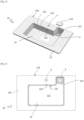
Fig.2 ] illustre une vue tridimensionnelle d'un plan-vasque selon l'invention ; - [
Fig.3 ] illustre une vue de dessus du plan-vasque de la [Fig.2 ] ; - [
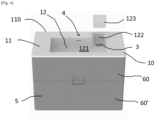
Fig.4 ] illustre une vue tridimensionnelle du plan-vasque de la [Fig.2 ] posé sur un meuble sous vasque ; - [
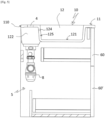
Fig.5 ] illustre une vue latérale en coupe du plan-vasque et du meuble sous vasque de la [Fig.4 ]. - En rappel liminaire à la description qui va suivre, un plan-vasque est un sanitaire destiné à une salle d'eau, une salle de bain, des toilettes ou encore une cuisine, sans que cela soit limitatif.
- Par définition un plan-vasque est composé d'un plan dans lequel est intégré une vasque ou bassine, le plan et la bassine étant venus de matière l'un avec l'autre.
- Nous obtenons ainsi un ensemble unique permettant d'avoir une place importante (plan) autour de la bassine, facile à entretenir et évitant toute reprise d'étanchéité entre la bassine et le plan.
- Il est illustré en trois dimensions sur la [
Fig.2 ], un plan-vasque 10 selon l'invention. - Le plan-vasque 1 selon l'invention comporte, de manière connue en soi, rappelée précédemment, un plan 11 et une vasque ou une bassine 12, le plan 11 et la bassine 12 étant venus de matière l'un avec l'autre.
- Généralement, la bassine 12 est positionnée au centre du plan 11. Le plan-vasque 11 est limité en arrière par un bord 110 qui, lors d'un montage du plan-vasque 1 selon l'invention, vient en appui contre un mur d'une pièce dans laquelle est situé le plan-vasque 1 selon l'invention.
- Entre la bassine et le bord arrière, le plan-vasque 1 selon l'invention comprend en outre un orifice 4 destiné à recevoir une robinetterie standard d'alimentation en eau de la bassine 2.
- De manière générale, l'orifice 4 est « centré » sur le plan 11 avec la bassine 12 : un centre de l'orifice 4 est aligné sur une perpendiculaire au bord arrière 11 avec un centre d'une section d'ouverture de la bassine 2, en vue de dessus.
- La bassine 12 comporte un fond 121 ainsi qu'un trop-plein 124 positionnés sur une partie remontante 125 de la bassine 2. Ici en arrière de la bassine 12, cette dernière comporte un renfoncement 122 qui s'étend en saillie. Ici, le renfoncement 124 s'étend en saillie vers l'arrière depuis une partie remontante 125 arrière de la bassine 12, le fond 121 se prolonge dans le renfoncement 124 et comporte l'orifice d'évacuation 3 des eaux usées.
- Ainsi, le renfoncement 122 se situe en arrière de la partie principale de la bassine 12, entre cette dernière et le bord arrière 110 du plan 11. Au surplus, le renfoncement 122 s'étend latéralement à l'orifice 4, ici à droite. En variante, le renfoncement 122 s'étend latéralement à gauche de l'orifice 4.
- Le plan-vasque 1 selon l'invention comporte en outre un cache 123 destiné à coopérer avec le renfoncement 122 se sorte à restaurer une continuité du plan 11 au-dessus du renfoncement 122.
- Ici, le cache 123 est plan. En variante de réalisation, le cache 123 est en forme de « L » de sorte à restaurer en partie la partie remontante 125 de la bassine 12 au niveau du renfoncement 122.
- Ainsi dans cette configuration, le renfoncement 122 est couvert et caché à la vue par le cache 123 en forme de L : seul un espace pour le passage des eaux usées reste ménagé entre le cache 123 et le fond 121 de la bassine 12.
- En référence aux
figures 4 et5 , nous allons décrire rapidement une installation d'un plan-vasque 1 selon l'invention sur un meuble 5 sous vasque. - Le meuble 5 sous vasque est ici un meuble comportant deux tiroirs 60 et 60' superposés et s'étendant sous le plan-vasque 1 selon l'invention.
- Le plan-vasque 1 selon l'invention est ici donc posé sur le meuble 5, le bord arrière 110 en appui sur un mur non représenté sur les figures.
- Au niveau du renfoncement 122, un système d'évacuation 8 est monté sur l'orifice d'évacuation 3 du plan-vasque 1 selon l'invention.
- Du fait de la configuration particulière du plan-vasque 1 selon l'invention, le système d'évacuation 8, encombrant, est « rejeté » en arrière, contre le mur sur lequel le bord arrière 110 est en appui.
- Ainsi le premier tiroir 60 situé en haut du meuble 5, juste en dessous du plan-vasque 1 selon l'invention, est entier car il ne comporte pas de découpe en « U », contrairement au montage des plans-vasques de l'art antérieur.
- L'espace sous le fond 121 de la bassine 12 et donc sous le plan-vasque 1 selon l'invention est ainsi optimisé, le volume antérieurement occupé par le système d'évacuation 8 étant récupéré.
- Les personnes à mobilité réduite en fauteuil roulant ou les personnes devant s'assoir devant le plan-vasque 1 selon l'invention ont de la place sous la bassine pour y positionner leurs jambes et faire face ainsi au plan-vasque 1 selon l'invention.
- De plus, le plan-vasque 1 selon l'invention, monté alors sur équerres de fixation, n'a pas besoin d'être réhaussé et reste à une hauteur confortable d'utilisation et d'accès, tout en offrant la surface du plan 11 pour y disposer différents ustensiles, de toilette notamment.
- Il résulte de l'utilisation d'un plan-vasque 1 selon l'invention une maximisation des volumes d'utilisation situés sous le plan 11 et la bassine 2.
- En utilisation posée sur un meuble 5 sous vasque, l'utilisation d'un plan-vasque 1 selon l'invention permet de s'affranchir de découper une forme en « U » ou de prévoir une telle forme au niveau du tiroir supérieur comme dans l'art antérieur.
- Dans une variante de réalisation, le renfoncement 122 s'étend en saillie d'une paroi montante de la bassine 12 qui est autre que la paroi montante 125 arrière : par exemple sur depuis une paroi montante latérale droite ou gauche de la bassine 12.
- Ici, la bassine 12 a une forme sensiblement de pavé, la section d'ouverture étant de section rectangulaire.
- Dans des variantes de réalisation, la bassine est une portion de sphère (section d'ouverture circulaire) ou une portion d'ellipsoïde (section d'ouverture en ellipse).
- Dans ces cas, le renfoncement 122 peut s'étendre en saillie depuis une partie de secteur située en arrière d'un plan vertical diamétral de la bassine perpendiculaire au bord arrière 110.
Claims (5)
- Plan-vasque (10) comportant un plan (11), une vasque ou bassine (12) venue de matière avec le plan (11) et un orifice d'évacuation des eaux usées (3), le plan-vasque (1) comportant en outre un renfoncement (122) s'étendant en saillie depuis une paroi montante (125) de la bassine (2), l'orifice d'évacuation des eaux usées (3) étant ménagé dans le renfoncement (122), ledit plan-vasque comprenant un cache (123) agencé de sorte à venir couvrir ledit renfoncement (122) afin d'assurer la continuité du plan (11) au-dessus dudit renfoncement (122), ledit cache (123) comportant une excroissance latérale agencée en sorte à reformer en partie ladite paroi remontante (125) au niveau dudit renfoncement (122), caractérisé en ce que ledit cache (123) couvre ledit renfoncement (122) de façon à ménager un espace pour le passage des eaux usées entre ledit cache (123) et un fond (121) de ladite bassine (12).
- Plan-vasque (10) selon la revendication 1, caractérisé en ce que ledit fond (121) s'étend dans le renfoncement (122).
- Plan-vasque (10) selon l'une quelconque des revendications 1 à 2, caractérisé en ce que le renfoncement (122) est situé entre la bassine et un bord arrière (110) du plan du plan-vasque (10).
- Plan-vasque (10) selon l'une quelconque des revendications 1 à 3, caractérisé en ce que, le plan-vasque comportant en outre un orifice (4) pour la robinetterie de distribution d'eau, le renfoncement (122) est ménagé latéralement à l'orifice (4).
- Plan-vasque (10) selon la revendication 4, caractérisé en ce que le renfoncement (122) est à gauche ou à droite de l'ouverture (4).
Applications Claiming Priority (1)
| Application Number | Priority Date | Filing Date | Title |
|---|---|---|---|
| FR2212929A FR3143047B1 (fr) | 2022-12-07 | 2022-12-07 | Plan-vasque a evacuation deportee |
Publications (1)
| Publication Number | Publication Date |
|---|---|
| EP4382683A1 true EP4382683A1 (fr) | 2024-06-12 |
Family
ID=85175964
Family Applications (1)
| Application Number | Title | Priority Date | Filing Date |
|---|---|---|---|
| EP23214748.8A Withdrawn EP4382683A1 (fr) | 2022-12-07 | 2023-12-06 | Plan-vasque à évacuation déportée |
Country Status (2)
| Country | Link |
|---|---|
| EP (1) | EP4382683A1 (fr) |
| FR (1) | FR3143047B1 (fr) |
Citations (3)
| Publication number | Priority date | Publication date | Assignee | Title |
|---|---|---|---|---|
| DE1797687U (de) * | 1959-07-07 | 1959-10-08 | Keramag Keramische Werke Ag | Aerzte-waschtisch. |
| US4777676A (en) * | 1984-11-30 | 1988-10-18 | Ericson Kurt Sture Birger | Sanitary appliances with an indirect outlet and hidden drainage mechanism |
| CA2822928C (fr) * | 2010-12-21 | 2018-08-14 | As Ip Holdco, Llc | Lavabo mural pour le lavage des mains permettant d'eviter une propagation de maladie infectieuse |
Family Cites Families (2)
| Publication number | Priority date | Publication date | Assignee | Title |
|---|---|---|---|---|
| EP3773098B1 (fr) * | 2018-03-29 | 2023-05-03 | Geberit International AG | Lavabo |
| CN114934566B (zh) * | 2022-06-30 | 2025-12-02 | 佛山市恒洁卫浴有限公司 | 面盆组件 |
-
2022
- 2022-12-07 FR FR2212929A patent/FR3143047B1/fr active Active
-
2023
- 2023-12-06 EP EP23214748.8A patent/EP4382683A1/fr not_active Withdrawn
Patent Citations (3)
| Publication number | Priority date | Publication date | Assignee | Title |
|---|---|---|---|---|
| DE1797687U (de) * | 1959-07-07 | 1959-10-08 | Keramag Keramische Werke Ag | Aerzte-waschtisch. |
| US4777676A (en) * | 1984-11-30 | 1988-10-18 | Ericson Kurt Sture Birger | Sanitary appliances with an indirect outlet and hidden drainage mechanism |
| CA2822928C (fr) * | 2010-12-21 | 2018-08-14 | As Ip Holdco, Llc | Lavabo mural pour le lavage des mains permettant d'eviter une propagation de maladie infectieuse |
Also Published As
| Publication number | Publication date |
|---|---|
| FR3143047A1 (fr) | 2024-06-14 |
| FR3143047B1 (fr) | 2025-04-25 |
Similar Documents
| Publication | Publication Date | Title |
|---|---|---|
| US10676908B2 (en) | Flush toilet | |
| CH620582A5 (fr) | ||
| FR2987633A1 (fr) | Cuve a compartiment separe avec systeme d'evacuation d'eau integre | |
| EP0056803A1 (fr) | Support mobile, notamment pour appareils sanitaires. | |
| FR2673095A1 (fr) | Lavabo mobile a plateau superieur articule. | |
| WO2010040948A1 (fr) | Dispositif de distribution d'eau de douche en circuit ferme et installation de douche recevant un tel dispositif | |
| CA2423216C (fr) | Bloc sanitaire pour vehicule, notamment ferroviaire | |
| EP4382683A1 (fr) | Plan-vasque à évacuation déportée | |
| EP1974103B1 (fr) | Carter de protection et de masquage d une cuvette de toilettes et cuvette ainsi equipee | |
| FR3040031A1 (fr) | Cabine de toilettes pour vehicule de transport public, destinee a accueillir une personne a mobilite reduite | |
| FR3042517A1 (fr) | Procede de fonctionnement d’un ensemble sanitaire comprenant une cuvette de wc rabattable et encastrable | |
| FR2657519A1 (fr) | Ensemble sanitaire pour soins hygieniques et ablutions a caractere rituel. | |
| US5050248A (en) | Combination toilet and urinal | |
| EP1641990B1 (fr) | Sanitaire public d'acces aise aux personnes handicapees | |
| KR102074151B1 (ko) | 좌변기 시트 | |
| KR101947613B1 (ko) | 화장실룸 내의 세면볼 설치 구조 | |
| FR2857037A1 (fr) | Sanitaire equipe d'un urinoir separe | |
| FR2715953A1 (fr) | Sanitaires à vasque déversoir. | |
| FR2671475A1 (fr) | Bac a bain de pieds combine avec une cabine de douche. | |
| FR2684529A1 (fr) | Siege pour faciliter la toilette dans une salle d'eau. | |
| FR2844444A1 (fr) | Urinoir escamotable | |
| EP3853420B1 (fr) | Urinoir pour femmes | |
| EP4388952A1 (fr) | Cabine de douche amovible | |
| CA1312707C (fr) | Dispositif d'evacuation d'air vicie pour toilettes | |
| FR2806113A1 (fr) | Lunette aspirante pour cuvette de toilettes |
Legal Events
| Date | Code | Title | Description |
|---|---|---|---|
| PUAI | Public reference made under article 153(3) epc to a published international application that has entered the european phase |
Free format text: ORIGINAL CODE: 0009012 |
|
| STAA | Information on the status of an ep patent application or granted ep patent |
Free format text: STATUS: THE APPLICATION HAS BEEN PUBLISHED |
|
| AK | Designated contracting states |
Kind code of ref document: A1 Designated state(s): AL AT BE BG CH CY CZ DE DK EE ES FI FR GB GR HR HU IE IS IT LI LT LU LV MC ME MK MT NL NO PL PT RO RS SE SI SK SM TR |
|
| STAA | Information on the status of an ep patent application or granted ep patent |
Free format text: STATUS: THE APPLICATION IS DEEMED TO BE WITHDRAWN |
|
| 18D | Application deemed to be withdrawn |
Effective date: 20241213 |