EP4382503A1 - Ceramic sintered body, ceramic substrate, mounting substrate, electronic device, and method for manufacturing ceramic sintered body - Google Patents
Ceramic sintered body, ceramic substrate, mounting substrate, electronic device, and method for manufacturing ceramic sintered body Download PDFInfo
- Publication number
- EP4382503A1 EP4382503A1 EP22853103.4A EP22853103A EP4382503A1 EP 4382503 A1 EP4382503 A1 EP 4382503A1 EP 22853103 A EP22853103 A EP 22853103A EP 4382503 A1 EP4382503 A1 EP 4382503A1
- Authority
- EP
- European Patent Office
- Prior art keywords
- sintered body
- ceramic sintered
- content
- ceramic
- terms
- Prior art date
- Legal status (The legal status is an assumption and is not a legal conclusion. Google has not performed a legal analysis and makes no representation as to the accuracy of the status listed.)
- Pending
Links
Images




Classifications
-
- C—CHEMISTRY; METALLURGY
- C04—CEMENTS; CONCRETE; ARTIFICIAL STONE; CERAMICS; REFRACTORIES
- C04B—LIME, MAGNESIA; SLAG; CEMENTS; COMPOSITIONS THEREOF, e.g. MORTARS, CONCRETE OR LIKE BUILDING MATERIALS; ARTIFICIAL STONE; CERAMICS; REFRACTORIES; TREATMENT OF NATURAL STONE
- C04B35/00—Shaped ceramic products characterised by their composition; Ceramics compositions; Processing powders of inorganic compounds preparatory to the manufacturing of ceramic products
- C04B35/01—Shaped ceramic products characterised by their composition; Ceramics compositions; Processing powders of inorganic compounds preparatory to the manufacturing of ceramic products based on oxide ceramics
- C04B35/10—Shaped ceramic products characterised by their composition; Ceramics compositions; Processing powders of inorganic compounds preparatory to the manufacturing of ceramic products based on oxide ceramics based on aluminium oxide
- C04B35/111—Fine ceramics
- C04B35/117—Composites
-
- H—ELECTRICITY
- H05—ELECTRIC TECHNIQUES NOT OTHERWISE PROVIDED FOR
- H05K—PRINTED CIRCUITS; CASINGS OR CONSTRUCTIONAL DETAILS OF ELECTRIC APPARATUS; MANUFACTURE OF ASSEMBLAGES OF ELECTRICAL COMPONENTS
- H05K1/00—Printed circuits
- H05K1/02—Details
- H05K1/03—Use of materials for the substrate
-
- C—CHEMISTRY; METALLURGY
- C04—CEMENTS; CONCRETE; ARTIFICIAL STONE; CERAMICS; REFRACTORIES
- C04B—LIME, MAGNESIA; SLAG; CEMENTS; COMPOSITIONS THEREOF, e.g. MORTARS, CONCRETE OR LIKE BUILDING MATERIALS; ARTIFICIAL STONE; CERAMICS; REFRACTORIES; TREATMENT OF NATURAL STONE
- C04B35/00—Shaped ceramic products characterised by their composition; Ceramics compositions; Processing powders of inorganic compounds preparatory to the manufacturing of ceramic products
- C04B35/01—Shaped ceramic products characterised by their composition; Ceramics compositions; Processing powders of inorganic compounds preparatory to the manufacturing of ceramic products based on oxide ceramics
- C04B35/10—Shaped ceramic products characterised by their composition; Ceramics compositions; Processing powders of inorganic compounds preparatory to the manufacturing of ceramic products based on oxide ceramics based on aluminium oxide
-
- C—CHEMISTRY; METALLURGY
- C04—CEMENTS; CONCRETE; ARTIFICIAL STONE; CERAMICS; REFRACTORIES
- C04B—LIME, MAGNESIA; SLAG; CEMENTS; COMPOSITIONS THEREOF, e.g. MORTARS, CONCRETE OR LIKE BUILDING MATERIALS; ARTIFICIAL STONE; CERAMICS; REFRACTORIES; TREATMENT OF NATURAL STONE
- C04B35/00—Shaped ceramic products characterised by their composition; Ceramics compositions; Processing powders of inorganic compounds preparatory to the manufacturing of ceramic products
- C04B35/622—Forming processes; Processing powders of inorganic compounds preparatory to the manufacturing of ceramic products
- C04B35/626—Preparing or treating the powders individually or as batches ; preparing or treating macroscopic reinforcing agents for ceramic products, e.g. fibres; mechanical aspects section B
- C04B35/63—Preparing or treating the powders individually or as batches ; preparing or treating macroscopic reinforcing agents for ceramic products, e.g. fibres; mechanical aspects section B using additives specially adapted for forming the products, e.g.. binder binders
- C04B35/6303—Inorganic additives
-
- C—CHEMISTRY; METALLURGY
- C04—CEMENTS; CONCRETE; ARTIFICIAL STONE; CERAMICS; REFRACTORIES
- C04B—LIME, MAGNESIA; SLAG; CEMENTS; COMPOSITIONS THEREOF, e.g. MORTARS, CONCRETE OR LIKE BUILDING MATERIALS; ARTIFICIAL STONE; CERAMICS; REFRACTORIES; TREATMENT OF NATURAL STONE
- C04B35/00—Shaped ceramic products characterised by their composition; Ceramics compositions; Processing powders of inorganic compounds preparatory to the manufacturing of ceramic products
- C04B35/622—Forming processes; Processing powders of inorganic compounds preparatory to the manufacturing of ceramic products
- C04B35/64—Burning or sintering processes
-
- H—ELECTRICITY
- H05—ELECTRIC TECHNIQUES NOT OTHERWISE PROVIDED FOR
- H05K—PRINTED CIRCUITS; CASINGS OR CONSTRUCTIONAL DETAILS OF ELECTRIC APPARATUS; MANUFACTURE OF ASSEMBLAGES OF ELECTRICAL COMPONENTS
- H05K1/00—Printed circuits
- H05K1/02—Details
- H05K1/03—Use of materials for the substrate
- H05K1/0306—Inorganic insulating substrates, e.g. ceramic, glass
-
- C—CHEMISTRY; METALLURGY
- C04—CEMENTS; CONCRETE; ARTIFICIAL STONE; CERAMICS; REFRACTORIES
- C04B—LIME, MAGNESIA; SLAG; CEMENTS; COMPOSITIONS THEREOF, e.g. MORTARS, CONCRETE OR LIKE BUILDING MATERIALS; ARTIFICIAL STONE; CERAMICS; REFRACTORIES; TREATMENT OF NATURAL STONE
- C04B2235/00—Aspects relating to ceramic starting mixtures or sintered ceramic products
- C04B2235/02—Composition of constituents of the starting material or of secondary phases of the final product
- C04B2235/30—Constituents and secondary phases not being of a fibrous nature
- C04B2235/32—Metal oxides, mixed metal oxides, or oxide-forming salts thereof, e.g. carbonates, nitrates, (oxy)hydroxides, chlorides
- C04B2235/3205—Alkaline earth oxides or oxide forming salts thereof, e.g. beryllium oxide
- C04B2235/3206—Magnesium oxides or oxide-forming salts thereof
-
- C—CHEMISTRY; METALLURGY
- C04—CEMENTS; CONCRETE; ARTIFICIAL STONE; CERAMICS; REFRACTORIES
- C04B—LIME, MAGNESIA; SLAG; CEMENTS; COMPOSITIONS THEREOF, e.g. MORTARS, CONCRETE OR LIKE BUILDING MATERIALS; ARTIFICIAL STONE; CERAMICS; REFRACTORIES; TREATMENT OF NATURAL STONE
- C04B2235/00—Aspects relating to ceramic starting mixtures or sintered ceramic products
- C04B2235/02—Composition of constituents of the starting material or of secondary phases of the final product
- C04B2235/30—Constituents and secondary phases not being of a fibrous nature
- C04B2235/32—Metal oxides, mixed metal oxides, or oxide-forming salts thereof, e.g. carbonates, nitrates, (oxy)hydroxides, chlorides
- C04B2235/3205—Alkaline earth oxides or oxide forming salts thereof, e.g. beryllium oxide
- C04B2235/3208—Calcium oxide or oxide-forming salts thereof, e.g. lime
-
- C—CHEMISTRY; METALLURGY
- C04—CEMENTS; CONCRETE; ARTIFICIAL STONE; CERAMICS; REFRACTORIES
- C04B—LIME, MAGNESIA; SLAG; CEMENTS; COMPOSITIONS THEREOF, e.g. MORTARS, CONCRETE OR LIKE BUILDING MATERIALS; ARTIFICIAL STONE; CERAMICS; REFRACTORIES; TREATMENT OF NATURAL STONE
- C04B2235/00—Aspects relating to ceramic starting mixtures or sintered ceramic products
- C04B2235/02—Composition of constituents of the starting material or of secondary phases of the final product
- C04B2235/30—Constituents and secondary phases not being of a fibrous nature
- C04B2235/32—Metal oxides, mixed metal oxides, or oxide-forming salts thereof, e.g. carbonates, nitrates, (oxy)hydroxides, chlorides
- C04B2235/3217—Aluminum oxide or oxide forming salts thereof, e.g. bauxite, alpha-alumina
-
- C—CHEMISTRY; METALLURGY
- C04—CEMENTS; CONCRETE; ARTIFICIAL STONE; CERAMICS; REFRACTORIES
- C04B—LIME, MAGNESIA; SLAG; CEMENTS; COMPOSITIONS THEREOF, e.g. MORTARS, CONCRETE OR LIKE BUILDING MATERIALS; ARTIFICIAL STONE; CERAMICS; REFRACTORIES; TREATMENT OF NATURAL STONE
- C04B2235/00—Aspects relating to ceramic starting mixtures or sintered ceramic products
- C04B2235/02—Composition of constituents of the starting material or of secondary phases of the final product
- C04B2235/30—Constituents and secondary phases not being of a fibrous nature
- C04B2235/32—Metal oxides, mixed metal oxides, or oxide-forming salts thereof, e.g. carbonates, nitrates, (oxy)hydroxides, chlorides
- C04B2235/3231—Refractory metal oxides, their mixed metal oxides, or oxide-forming salts thereof
- C04B2235/3232—Titanium oxides or titanates, e.g. rutile or anatase
-
- C—CHEMISTRY; METALLURGY
- C04—CEMENTS; CONCRETE; ARTIFICIAL STONE; CERAMICS; REFRACTORIES
- C04B—LIME, MAGNESIA; SLAG; CEMENTS; COMPOSITIONS THEREOF, e.g. MORTARS, CONCRETE OR LIKE BUILDING MATERIALS; ARTIFICIAL STONE; CERAMICS; REFRACTORIES; TREATMENT OF NATURAL STONE
- C04B2235/00—Aspects relating to ceramic starting mixtures or sintered ceramic products
- C04B2235/02—Composition of constituents of the starting material or of secondary phases of the final product
- C04B2235/30—Constituents and secondary phases not being of a fibrous nature
- C04B2235/32—Metal oxides, mixed metal oxides, or oxide-forming salts thereof, e.g. carbonates, nitrates, (oxy)hydroxides, chlorides
- C04B2235/327—Iron group oxides, their mixed metal oxides, or oxide-forming salts thereof
- C04B2235/3272—Iron oxides or oxide forming salts thereof, e.g. hematite, magnetite
-
- C—CHEMISTRY; METALLURGY
- C04—CEMENTS; CONCRETE; ARTIFICIAL STONE; CERAMICS; REFRACTORIES
- C04B—LIME, MAGNESIA; SLAG; CEMENTS; COMPOSITIONS THEREOF, e.g. MORTARS, CONCRETE OR LIKE BUILDING MATERIALS; ARTIFICIAL STONE; CERAMICS; REFRACTORIES; TREATMENT OF NATURAL STONE
- C04B2235/00—Aspects relating to ceramic starting mixtures or sintered ceramic products
- C04B2235/02—Composition of constituents of the starting material or of secondary phases of the final product
- C04B2235/30—Constituents and secondary phases not being of a fibrous nature
- C04B2235/34—Non-metal oxides, non-metal mixed oxides, or salts thereof that form the non-metal oxides upon heating, e.g. carbonates, nitrates, (oxy)hydroxides, chlorides
- C04B2235/3418—Silicon oxide, silicic acids or oxide forming salts thereof, e.g. silica sol, fused silica, silica fume, cristobalite, quartz or flint
-
- C—CHEMISTRY; METALLURGY
- C04—CEMENTS; CONCRETE; ARTIFICIAL STONE; CERAMICS; REFRACTORIES
- C04B—LIME, MAGNESIA; SLAG; CEMENTS; COMPOSITIONS THEREOF, e.g. MORTARS, CONCRETE OR LIKE BUILDING MATERIALS; ARTIFICIAL STONE; CERAMICS; REFRACTORIES; TREATMENT OF NATURAL STONE
- C04B2235/00—Aspects relating to ceramic starting mixtures or sintered ceramic products
- C04B2235/70—Aspects relating to sintered or melt-casted ceramic products
- C04B2235/72—Products characterised by the absence or the low content of specific components, e.g. alkali metal free alumina ceramics
-
- C—CHEMISTRY; METALLURGY
- C04—CEMENTS; CONCRETE; ARTIFICIAL STONE; CERAMICS; REFRACTORIES
- C04B—LIME, MAGNESIA; SLAG; CEMENTS; COMPOSITIONS THEREOF, e.g. MORTARS, CONCRETE OR LIKE BUILDING MATERIALS; ARTIFICIAL STONE; CERAMICS; REFRACTORIES; TREATMENT OF NATURAL STONE
- C04B2235/00—Aspects relating to ceramic starting mixtures or sintered ceramic products
- C04B2235/70—Aspects relating to sintered or melt-casted ceramic products
- C04B2235/80—Phases present in the sintered or melt-cast ceramic products other than the main phase
- C04B2235/85—Intergranular or grain boundary phases
-
- C—CHEMISTRY; METALLURGY
- C04—CEMENTS; CONCRETE; ARTIFICIAL STONE; CERAMICS; REFRACTORIES
- C04B—LIME, MAGNESIA; SLAG; CEMENTS; COMPOSITIONS THEREOF, e.g. MORTARS, CONCRETE OR LIKE BUILDING MATERIALS; ARTIFICIAL STONE; CERAMICS; REFRACTORIES; TREATMENT OF NATURAL STONE
- C04B2235/00—Aspects relating to ceramic starting mixtures or sintered ceramic products
- C04B2235/70—Aspects relating to sintered or melt-casted ceramic products
- C04B2235/96—Properties of ceramic products, e.g. mechanical properties such as strength, toughness, wear resistance
Definitions
- the disclosed embodiment relates to a ceramic sintered body, a ceramic substrate, a mounting substrate, an electronic device, and a method for manufacturing a ceramic sintered body.
- Patent Document 1 discloses a ceramic substrate containing Al 2 O 3 (alumina) as a main component and TiOz (titanium oxide) as an additive.
- Cited Document 1 also describes that an Al 2 O 3 powder having a particle size from 120 nm to 500 nm is used and that the powder has a particle size of 1 ⁇ m or less.
- Patent Document 2 describes a mounting substrate in which a copper plate and an alumina substrate in contact with each other are heated in an inert atmosphere to dispose the copper plate on the alumina substrate.
- the method disclosed in Patent Document 2 is referred to as an active metal bonding (AMB) method.
- Patent Document 3 describes a mounting substrate prepared using a direct bonding method of ceramic and copper.
- the method disclosed in Patent Document 3 is referred to as a direct copper bonding (DCB) method.
- Cited Document 4 describes a method of manufacturing a circuit board in which a metal plate including copper or a copper alloy is bonded to a surface of a substrate made of alumina or the like using a hot pressing process.
- a ceramic sintered body contains Al 2 O 3 (alumina) and an additive, in which a content of Al 2 O 3 is 94 mass% or greater.
- the additive contains SiOz (silica), CaO (calcia), MgO (magnesia), TiOz (titanium oxide), and Fe 2 O 3 (iron oxide).
- a content of Ti (titanium) in terms of TiOz is 120 ppm or greater
- a content of Fe (iron) in terms of Fe 2 O 3 is 180 ppm or greater.
- FIG. 1 is a side view illustrating an overview of a mounting substrate 1 according to the embodiment.
- the mounting substrate 1 illustrated in FIG. 1 includes a ceramic substrate 2 including a ceramic sintered body and a metal layer 3. Since the ceramic sintered body is substantially the same as the ceramic substrate 2, a reference numeral unique to the ceramic sintered body in the drawings is omitted. In other words, the reference numeral of the ceramic sintered body in the drawing is 2.
- the ceramic sintered body may be used for structural members such as a rod body, a block body, and a hollow member.
- the ceramic substrate 2 is a plate-shaped member including a ceramic sintered body containing Al 2 O 3 (alumina) and additives and having an Al 2 O 3 content of 94 mass% or greater, and having a thickness of, for example, about from 0.2 to 1 mm.
- the additive contains SiOz (silica), CaO (calcia), MgO (magnesia), TiO 2 (titanium oxide), and Fe 2 O 3 (iron oxide).
- a content of Ti (titanium) in terms of TiOz is 120 ppm or greater, and a content of Fe (iron) in terms of Fe 2 O 3 is 180 ppm or greater.
- the ceramic substrate 2 has high mechanical strength.
- the ceramic sintered body has excellent thermal shock resistance.
- the content of Ti in terms of TiOz and the content of Fe in terms of Fe 2 O 3 can be determined by, for example, the following method.
- quantitative analysis of Ti and Fe in the ceramic sintered body is performed using an ICP emission spectrophotometer (ICP).
- ICP ICP emission spectrophotometer
- the content (ICP content) in terms of TiOz as an oxide is determined from the content of Ti measured by ICP
- the content (ICP content) in terms of Fe 2 O 3 as an oxide is determined from the content of Fe measured by ICP.
- the reason why the ceramic substrate 2 can improve the mechanical strength is considered as follows, for example. That is, when TiOz is contained in the ceramic sintered body constituting the ceramic substrate 2, TiOz is located at a crystal grain boundary of the ceramic sintered body. When the content of TiOz in the ceramic sintered body is 120 ppm or greater, TiOz located at the crystal grain boundary of the ceramic sintered body functions as a resistor that suppresses the progress of a crack that is likely to occur at the crystal grain boundary.
- TiOz located at the crystal grain boundary of the ceramic sintered body serves as a crystal nucleus for a sintering aid component (for example, SiOz, CaO, and MgO), it is possible to polycrystallize and toughen the crystal grain boundary, and it is possible to suppress occurrence of a crack. Therefore, when the ceramic sintered body contains TiOz at a suitable content, the mechanical strength of the ceramic substrate 2 can be improved.
- a sintering aid component for example, SiOz, CaO, and MgO
- the ceramic sintered body constituting the ceramic substrate 2 contains Fe 2 O 3
- Fe 2 O 3 is located at the crystal grain boundary of the ceramic sintered body.
- the content of Fe 2 O 3 in the ceramic sintered body is 180 ppm or greater
- Fe 2 O 3 located at the crystal grain boundary of the ceramic sintered body causes a phenomenon of moving the crystal grain boundary and moving TiOz located at the crystal grain boundary. Therefore, when the ceramic sintered body contains Fe 2 O 3 at a suitable content, the crystal grain boundaries and TiOz can be suitably dispersed.
- the mechanical strength of the ceramic substrate 2 is improved as the crystal grain boundary and the dispersion of TiOz proceed. Therefore, according to the ceramic substrate 2 of the embodiment, the mechanical strength of the ceramic substrate 2 can be improved.
- the ceramic sintered body may contain 96 mass% or greater and 98 mass% or less of Al 2 O 3 .
- the content of Al 2 O 3 is less than 96 mass%, the proportion of sintering aid components (for example, SiOz, CaO, and MgO) in the ceramic sintered body increases, and therefore, sintering between aluminum oxides (Al 2 O 3 ) as the main component may become insufficient.
- the content of Al 2 O 3 is greater than 98 mass%, the crystal of Al 2 O 3 is hardly densified, and therefore, the mechanical strength of the ceramic substrate 2 may be reduced.
- the content of Ti in terms of TiOz is preferably 350 ppm or less.
- the content of TiOz is greater than 350 ppm, the distribution of TiOz located at the crystal grain boundary of the ceramic sintered body is biased, and therefore, the mechanical strength of the ceramic substrate 2 may be reduced.
- the content of Fe in terms of Fe 2 O 3 is preferably greater than the content of Ti in terms of TiOz.
- the content of Fe in terms of Fe 2 O 3 in the ceramic sintered body constituting the ceramic substrate 2 is preferably 410 ppm or less.
- the ceramic sintered body does not contain ZrOz (zirconia).
- ZrOz zirconia
- the raw material cost can be suppressed.
- thermal conductivity can be improved and a dielectric loss can be reduced.
- the thermal conductivity is 23 W/m ⁇ K
- the dielectric loss at 1 MHz is 2 ⁇ 10 -4 .
- the thermal conductivity is 25 W/m ⁇ K
- the dielectric loss at 1 MHz is 0.4 ⁇ 10 -4 .
- effective characteristic values are obtained also from the viewpoint of the thermal conductivity and the dielectric loss.
- TiOz and Fe 2 O 3 are located at the crystal grain boundary.
- the positions of TiOz and Fe 2 O 3 in the ceramic sintered body can be determined by, for example, observing the surface of the ceramic substrate 2 using a scanning electron microscope (SEM) or an energy dispersive X-ray analyzer (EDX) attached to a transmission electron microscope (TEM).
- SEM scanning electron microscope
- EDX energy dispersive X-ray analyzer
- TEM transmission electron microscope
- FIG. 2 is a TEM photograph of the surface of the ceramic substrate 2 according to the embodiment.
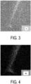
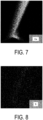
- FIGs. 3 to 9 are each an EDX image showing an analysis result of distribution of a specific element in the same place as the TEM photograph illustrated in FIG. 2 .
- the EDX image of FIG. 3 is a composite image showing the analysis result of the distribution of O (oxygen).
- the EDX image of FIG. 4 is a composite image showing the analysis result of the distribution of Mg (magnesium).
- the EDX image of FIG. 5 is a composite image showing the analysis result of the distribution of Al (aluminum).
- the EDX image of FIG. 6 is a composite image showing the analysis result of the distribution of Si (silicon).
- the EDX image of FIG. 7 is a composite image showing the analysis result of the distribution of Ca (calcium).
- the EDX image of FIG. 8 is a composite image showing the analysis result of the distribution of Ti (titanium).
- FIG. 9 is a composite image showing the analysis result of the distribution of Fe (iron).
- a region having a large amount of a specific element that is, O, Mg, Al, Si, Ca, Ti, or Fe is shown in white.
- TiOz and Fe 2 O 3 are located at the crystal grain boundary of the ceramic sintered body similarly to the sintering aid components (for example, SiOz, CaO, and MgO).
- the metal layer 3 is located on the ceramic substrate 2.
- the metal layer 3 is, for example, a metal plate.
- the thickness of the metal plate can be, for example, about from 0.1 to 5 mm.
- As a material of the metal plate for example, copper or aluminum can be used.
- the metal plate can be bonded onto the ceramic substrate using, for example, an AMB (Active Metal Bonding) method disclosed in Patent Document 2, a DCB (Direct Copper Bonding) method disclosed in Patent Document 3, a method using hot pressing disclosed in Patent Document 4, or the like.
- the bonding conditions of the ceramic substrate 2 and the metal plate 3 are not limited to the conditions in the ranges disclosed in Patent Documents 2 to 4.
- the metal layer 3 may be, for example, a metal paste containing a noble metal such as copper, silver, or platinum as a main component.
- the thickness of the metal paste can be, for example, about from 1 to 40 ⁇ m.
- the metal layer 3 may contain Ti and Fe at least on a side of the metal layer 3 adjacent to the ceramic substrate 2. Since the ceramic substrate 2 contains Fe and Ti, Ti and Fe diffuse from the ceramic substrate 2 to the metal layer 3 at the time of bonding, thereby increasing the bonding strength between the ceramic substrate 2 and the metal layer 3.
- An alloy or a compound containing Ti, Fe, and Cu may be located in the metal layer 3.
- the metal layer 3 may be located on both surfaces of the ceramic substrate 2. Furthermore, the metal plate 3 may be located on one surface of the ceramic substrate 2, and a heat dissipation member may be located on the other surface.
- FIG. 10 is a side view illustrating an example of the electronic device 10 according to the embodiment.
- the electronic device 10 includes the mounting substrate 1 and an electronic component 4 located on the metal layer 3 of the mounting substrate 1.
- a heat sink or a channel member for dissipating heat from the electronic component 4 may be located on a surface of the mounting substrate 1 opposite to a surface on which the metal layer 3 is located.
- a semiconductor element such as a light emitting diode (LED) element, an insulated gate bipolar transistor (IGBT) element, an intelligent power module (IPM) element, a metal oxide film field-effect transistor (MOSFET) element, a freewheeling diode (FWD) element, a giant transistor (GTR) element, or a Schottky barrier diode (SBD), or a heating element such as a sublimation type thermal printer head element, a thermal inkjet printer head element, or a Peltier element can be used.
- LED light emitting diode
- IGBT intelligent power module
- MOSFET metal oxide film field-effect transistor
- FWD freewheeling diode
- GTR giant transistor
- SBD Schottky barrier diode
- a heating element such as a sublimation type thermal printer head element, a thermal inkjet printer head element, or a Peltier element
- Al 2 O 3 (aluminum) powder is prepared as a main raw material.
- powders of SiO 2 (silica), CaO (calcia), MgO (magnesia), TiO 2 (titanium oxide), and Fe 2 O 3 (iron oxide) are prepared.
- a powder of Al 2 O 3 and a powder of an additive are blended such that the content of Al 2 O 3 is 94 mass% or greater to produce a blended powder.
- a blending composition at this time is as follows. Al contained in the ceramic substrate 2 is 94 mass% or greater in terms of Al 2 O 3 . The sum of values obtained by converting Si into SiOz, Ca into CaO, Mg into MgO, Ti into TiO 2 , and Fe into Fe 2 O 3 (i.e., the additive contained in the ceramic substrate 2) is 1.0 mass% or greater and 6.0 mass% or less. A mass ratio of SiOz in the additive is, for example, 38 mass% or greater and 60 mass% or less.
- a mass ratio of CaO in the additive is, for example, 20 mass% or greater and 43 mass% or less.
- a mass ratio of MgO in the additive is, for example, 14 mass% or greater and 37 mass% or less.
- a content of Fe contained as an impurity in the powder of Al 2 O 3 in terms of Fe 2 O 3 is from 100 to 300 ppm.
- a content (blended content) of Ti in terms of TiOz be 0.48 mass% or greater and 1.18 mass% or less, and a content (blended content) of Fe in terms of Fe 2 O 3 be 0.48 mass% or greater.
- a solvent and a binder are added to a blended powder produced by blending the powder of Al 2 O 3 and the powder of the additive, and then they are mixed and pulverized by, for example, a ball mill or the like to prepare a slurry.
- the slurry is spray-dried using a spray dryer to produce granules.
- the granules are molded by a press molding method, a roll compaction molding method, or the like to prepare a molded body having a desired shape.
- a slurry may be molded by a doctor blade method to prepare a sheet-shaped molded body.
- a cut-out, a hole, a recess, or the like may be formed in the prepared molded body by a drill, a laser, or the like as necessary.
- the molded body is subjected to heat treatment to perform degreasing, and then the molded body is fired.
- the firing temperature is, for example, in a range of 1500°C or higher and 1600°C or lower.
- the composition after firing is the same as the blended composition except for TiO 2 and Fe 2 O 3 .
- the ceramic sintered body produced by firing the molded body may be subjected to polishing, grinding, drilling, laser processing, blasting, or the like as necessary.
- the ceramic substrate 2 is produced using the ceramic sintered body according to the embodiment.
- a ceramic sintered body (Samples Nos. 3 to 8) of Example 1 was prepared as follows. A powder of Al 2 O 3 and a powder of the additive were blended such that the contents (mass%) of Al 2 O 3 and the additive contained in the ceramic sintered body were the contents shown in Table 1 to prepare a blended powder. Next, after a solvent and a binder were added to the blended powder, granules were prepared through a slurry, and the granules were reshaped as desired by press molding to prepare a molded body. Thereafter, the binder component was removed by degreasing, and then the molded body was fired to produce a ceramic sintered body (Samples Nos. 3 to 8).
- the content of the metal element (Ti, Fe) in the produced ceramic sintered body was measured by ICP, and the content (ICP content) in terms of oxide (TiO 2 , Fe 2 O 3 ) was determined.
- the resulting value of each ICP content is shown in Table 1.
- the underlined numerical values of the ICP contents are values estimated using an approximate function indicating a relationship between a blended content (that is, in the additive, a content of Ti in terms of TiO 2 and a content of Fe in terms of Fe 2 O 3 ) and an ICP content.
- FIG. 11 is a graph illustrating an example of an approximate function showing a relationship between a blended content and an ICP content.
- FIG. 11 shows an approximate function indicating the relationship between the blended content and the ICP content for TiOz and an approximate function indicating the relationship between the blended content and the ICP content for Fe 2 O 3 .
- Each approximate function is generated based on each measured value of the ICP content with respect to the blended content.
- the numerical value of the underlined ICP content can be estimated by applying each blended content to each approximate function shown in FIG. 11 .
- the underlined numerical value (that is, the estimated value) of the ICP content is a numerical value obtained by rounding off the decimal point.
- JIS piece Three-Point Bending Strength Test and Thermal Shock Resistance Test Samples of the produced ceramic sintered bodies were each processed into a test piece of 3 mm ⁇ 4 mm ⁇ 40 mm (hereinafter also referred to as "JIS piece").
- the JIS piece was prepared by a press molding method. Using this JIS piece, a three-point bending strength test and a thermal shock resistance test were performed. The results of the thermal shock resistance test will be described below.
- the three-point bending strength of each sample was measured in accordance with JIS R 1601-2008.
- a crosshead speed used for measuring the three-point bending strength was 0.5 mm/min.
- the obtained results of the three-point bending strength test are as shown in Table 1.
- the thermal shock resistance test was performed in accordance with JIS R 1648-2002.
- the crosshead speed in the thermal shock resistance test was also 0.5 mm/min.
- a ceramic sintered body of Comparative Example 1 (Sample No. 1) was prepared under the same conditions as in Example 1 except that the powder of TiOz was not blended as an additive to the powder of Al 2 O 3 .
- the ICP content for a metal element (Ti, Fe) in the produced ceramic sintered body was measured and estimated in the same manner as described above.
- the resulting value of each ICP content is shown in Table 1.
- the ICP content of TiOz in the ceramic sintered body is not 0. This is because the powder of Al 2 O 3 to be blended contains TiOz as an impurity.
- the produced ceramic sintered body was subjected to the same three-point bending strength test as in Example 1.
- the result of the three-point bending strength test is as shown in Table 1.
- a ceramic sintered body of Comparative Example 2 (Sample No. 2) was prepared under the same conditions as in Example 1 except that the powder of Fe 2 O 3 was not blended as an additive to the powder of Al 2 O 3 .
- the ICP content for a metal element (Ti, Fe) in the produced ceramic sintered body was measured and estimated in the same manner as in Example 1.
- the resulting value of each ICP content is shown in Table 1.
- the ICP content of Fe 2 O 3 in the ceramic sintered body is not 0. This is because the Al 2 O 3 powder to be blended contains Fe 2 O 3 as an impurity.
- the produced ceramic sintered body was subjected to the same three-point bending strength test as in Example 1.
- the result of the three-point bending strength test is as shown in Table 1.
- the content of Ti (titanium) in terms of TiOz be 120 ppm or greater, and the content of Fe (iron) in terms of Fe 2 O 3 be 180 ppm or greater.
- a ceramic sintered body (Samples Nos. 9 to 12) was prepared by changing the contents (mass%) of Al 2 O 3 and the additive. The conditions were the same as in Example 1 except that the contents (mass%) of Al 2 O 3 and the additive contained in the ceramic sintered body were changed to the contents shown in Table 2. Samples Nos. 9, 10, and 12 are the same as Samples Nos. 7, 5, and 8, respectively.
- Example 2 The same measurement and estimation of the ICP content as in Example 1 and the same three-point bending strength test as in Example 1 were performed. The resulting value of each ICP content is shown in Table 2. The obtained results of the three-point bending strength test are as shown in Table 2.
- the ceramic sintered body preferably contains 96 mass% or greater and 98 mass% or less of Al 2 O 3 .
- the content of Ti in terms of TiOz is preferably 350 ppm or less.
- a ceramic sintered body (Samples Nos. 13 and 14) was prepared by changing the content of Fe in terms of Fe 2 O 3 and the content of Ti in terms of TiOz in the ceramic sintered body.
- the conditions were the same as in Example 1 except that the content of Fe in terms of Fe 2 O 3 and the content of Ti in terms of TiOz in the ceramic sintered body were changed to the ICP contents shown in Table 3, and the contents (mass%) of Al 2 O 3 and the additive contained in the ceramic sintered body were changed to the contents shown in Table 3.
- the ICP content was measured and estimated in the same manner as in Example 1. The resulting value of each ICP content is shown in Table 3.
- test substrate 24 mm ⁇ 40 mm ⁇ 0.32 mm
- the three-point bending strength of each sample was measured in accordance with JIS R 1601-2008.
- a crosshead speed used for measuring the three-point bending strength was 5 mm/min.
- the obtained results of the three-point bending strength test are as shown in Table 3.
- the content of Fe in terms of Fe 2 O 3 is preferably greater than the content of Ti in terms of TiOz.
- a ceramic sintered body (Samples Nos. 18 to 20, 22, and 23) of Example 4 was prepared as follows.
- a powder of Al 2 O 3 and a powder of the additive were blended such that the contents (mass%) of Al 2 O 3 and the additive contained in the ceramic sintered body were the contents shown in Table 4 to prepare a blended powder.
- the content of Ti in terms of TiOz and the content of Fe in terms of Fe 2 O 3 in the additive were the blended contents shown in Table 4.
- granules were prepared through a slurry, and the granules were reshaped as desired by press molding to prepare a molded body.
- Samples Nos. 18 to 20, 22, and 23 are the same as Samples Nos. 3, 5, 6, 7, and 11, respectively.
- Example No. 16 A ceramic sintered body of Comparative Example 3 (Sample No. 16) was prepared under the same conditions as in Example 4 except that the powder of TiO2 was not blended as an additive to the powder of Al 2 O 3 .
- Sample No. 16 is the same sample as Sample No. 1.
- the produced ceramic sintered body was subjected to the same three-point bending strength test as in Example 4.
- the result of the three-point bending strength test is as shown in Table 4.
- Example No. 17 A ceramic sintered body of Comparative Example 4 (Sample No. 17) was prepared under the same conditions as in Example 4 except that the powder of Fe 2 O 3 was not blended as an additive to the powder of Al 2 O 3 .
- Sample No. 17 is the same sample as Sample No. 2.
- the produced ceramic sintered body was subjected to the same three-point bending strength test as in Example 4.
- the result of the three-point bending strength test is as shown in Table 4.
- a ceramic sintered body of Comparative Example 5 (Sample No. 21) was produced under the same conditions as in Example 4 except that the content of Ti in the additive in terms of TiOz was changed to the blended content shown in Table 4.
- the produced ceramic sintered body was subjected to the same three-point bending strength test as in Example 4.
- the result of the three-point bending strength test is as shown in Table 4.
- the content of Ti in terms of TiOz be 0.48 mass% or greater and 1.18 mass% or less, and the content of Fe in terms of Fe 2 O 3 be 0.48 mass% or greater.
- the thermal shock resistance test was performed using Samples Nos. 1, 2, and 8 in Example 1.
- the results of the thermal shock resistance test are as shown in Table 5.
- Samples Nos. 1 and 2 are comparative examples, and Sample No. 8 is an example.
- Table 5 also shows the results of evaluating the three-point bending strength of the JIS piece without performing the thermal shock resistance test. The three-point bending strength of the JIS piece that was not subjected to the thermal shock resistance test is provided without a description of temperature.
- Table 5 shows the three-point bending strength of the JIS piece measured by heating the JIS piece to 190°C, 240 °C, 265°C, and 290°C, then dropping the JIS piece into water having a water temperature of 10°C to rapidly cool the JIS piece, and then performing a three-point bending test.
Landscapes
- Chemical & Material Sciences (AREA)
- Engineering & Computer Science (AREA)
- Ceramic Engineering (AREA)
- Manufacturing & Machinery (AREA)
- Materials Engineering (AREA)
- Structural Engineering (AREA)
- Organic Chemistry (AREA)
- Inorganic Chemistry (AREA)
- Composite Materials (AREA)
- Microelectronics & Electronic Packaging (AREA)
- Compositions Of Oxide Ceramics (AREA)
Abstract
Description
- The disclosed embodiment relates to a ceramic sintered body, a ceramic substrate, a mounting substrate, an electronic device, and a method for manufacturing a ceramic sintered body.
- In the known art, since a ceramic substrate using a ceramic sintered body as a substrate has excellent insulation properties and thermal conductivity, the ceramic substrate may be used as a mounting substrate for mounting an electronic component. For example,
Patent Document 1 discloses a ceramic substrate containing Al2O3 (alumina) as a main component and TiOz (titanium oxide) as an additive.Cited Document 1 also describes that an Al2O3 powder having a particle size from 120 nm to 500 nm is used and that the powder has a particle size of 1 µm or less. -
Patent Document 2 describes a mounting substrate in which a copper plate and an alumina substrate in contact with each other are heated in an inert atmosphere to dispose the copper plate on the alumina substrate. The method disclosed inPatent Document 2 is referred to as an active metal bonding (AMB) method. In addition,Patent Document 3 describes a mounting substrate prepared using a direct bonding method of ceramic and copper. The method disclosed inPatent Document 3 is referred to as a direct copper bonding (DCB) method.Cited Document 4 describes a method of manufacturing a circuit board in which a metal plate including copper or a copper alloy is bonded to a surface of a substrate made of alumina or the like using a hot pressing process. -
- Patent Document 1:
JP 2017-218368 A - Patent Document 2:
JP S63-166774 A - Patent Document 3:
JP H5-243725 A - Patent Document 4:
JP 2020-145335 A - In an aspect of an embodiment, a ceramic sintered body contains Al2O3 (alumina) and an additive, in which a content of Al2O3 is 94 mass% or greater. The additive contains SiOz (silica), CaO (calcia), MgO (magnesia), TiOz (titanium oxide), and Fe2O3 (iron oxide). In the ceramic sintered body, a content of Ti (titanium) in terms of TiOz is 120 ppm or greater, and a content of Fe (iron) in terms of Fe2O3 is 180 ppm or greater.
-
-
FIG. 1 is a side view illustrating an overview of a mounting substrate according to an embodiment. -
FIG. 2 is a TEM photograph of a surface of a ceramic sintered body according to the embodiment. -
FIG. 3 is an EDX image showing an analysis result of distribution of a specific element in the same place as the TEM photograph illustrated inFIG. 2 . -
FIG. 4 is an EDX image showing an analysis result of distribution of a specific element in the same place as the TEM photograph illustrated inFIG. 2 . -
FIG. 5 is an EDX image showing an analysis result of distribution of a specific element in the same place as the TEM photograph illustrated inFIG. 2 . -
FIG. 6 is an EDX image showing an analysis result of distribution of a specific element in the same place as the TEM photograph illustrated inFIG. 2 . -
FIG. 7 is an EDX image showing an analysis result of distribution of a specific element in the same place as the TEM photograph illustrated inFIG. 2 . -
FIG. 8 is an EDX image showing an analysis result of distribution of a specific element in the same place as the TEM photograph illustrated inFIG. 2 . -
FIG. 9 is an EDX image showing an analysis result of distribution of a specific element in the same place as the TEM photograph illustrated inFIG. 2 . -
FIG. 10 is a side view illustrating an example of an electronic device according to the embodiment. -
FIG. 11 is a graph illustrating an example of an approximate function showing a relationship between a blended content and an ICP content. - Hereinafter, embodiments of a ceramic sintered body, a ceramic substrate, a mounting substrate, an electronic device, and a method for manufacturing a ceramic sintered body disclosed in the present application will be described with reference to the accompanying drawings. The present disclosure is not limited by the following embodiments. Note that the drawings are schematic and that the dimensional relationships between elements, the proportions of the elements, and the like may differ from the actual ones. There may be differences between the drawings in terms of dimensional relationships, proportions, and the like.
- In the embodiments described below, expressions such as "constant", "orthogonal", "perpendicular", and "parallel" may be used, but these expressions do not mean exactly "constant", "orthogonal", "perpendicular", and "parallel". In other words, it is assumed that the above expressions allow deviations in manufacturing accuracy, installation accuracy, or the like.
-
FIG. 1 is a side view illustrating an overview of amounting substrate 1 according to the embodiment. Themounting substrate 1 illustrated inFIG. 1 includes aceramic substrate 2 including a ceramic sintered body and ametal layer 3. Since the ceramic sintered body is substantially the same as theceramic substrate 2, a reference numeral unique to the ceramic sintered body in the drawings is omitted. In other words, the reference numeral of the ceramic sintered body in the drawing is 2. The ceramic sintered body may be used for structural members such as a rod body, a block body, and a hollow member. - The
ceramic substrate 2 is a plate-shaped member including a ceramic sintered body containing Al2O3 (alumina) and additives and having an Al2O3 content of 94 mass% or greater, and having a thickness of, for example, about from 0.2 to 1 mm. The additive contains SiOz (silica), CaO (calcia), MgO (magnesia), TiO2 (titanium oxide), and Fe2O3 (iron oxide). - For the
ceramic substrate 2 according to the embodiment, in the ceramic sintered body, a content of Ti (titanium) in terms of TiOz is 120 ppm or greater, and a content of Fe (iron) in terms of Fe2O3 is 180 ppm or greater. Thus, when using the ceramic sintered body according to the embodiment, theceramic substrate 2 has high mechanical strength. According to the embodiment, the ceramic sintered body has excellent thermal shock resistance. - In the ceramic sintered body, the content of Ti in terms of TiOz and the content of Fe in terms of Fe2O3 can be determined by, for example, the following method. First, quantitative analysis of Ti and Fe in the ceramic sintered body is performed using an ICP emission spectrophotometer (ICP). Then, the content (ICP content) in terms of TiOz as an oxide is determined from the content of Ti measured by ICP, and the content (ICP content) in terms of Fe2O3 as an oxide is determined from the content of Fe measured by ICP.
- When using the ceramic sintered body according to the embodiment, the reason why the
ceramic substrate 2 can improve the mechanical strength is considered as follows, for example. That is, when TiOz is contained in the ceramic sintered body constituting theceramic substrate 2, TiOz is located at a crystal grain boundary of the ceramic sintered body. When the content of TiOz in the ceramic sintered body is 120 ppm or greater, TiOz located at the crystal grain boundary of the ceramic sintered body functions as a resistor that suppresses the progress of a crack that is likely to occur at the crystal grain boundary. Since TiOz located at the crystal grain boundary of the ceramic sintered body serves as a crystal nucleus for a sintering aid component (for example, SiOz, CaO, and MgO), it is possible to polycrystallize and toughen the crystal grain boundary, and it is possible to suppress occurrence of a crack. Therefore, when the ceramic sintered body contains TiOz at a suitable content, the mechanical strength of theceramic substrate 2 can be improved. - When the ceramic sintered body constituting the
ceramic substrate 2 contains Fe2O3, Fe2O3 is located at the crystal grain boundary of the ceramic sintered body. When the content of Fe2O3 in the ceramic sintered body is 180 ppm or greater, Fe2O3 located at the crystal grain boundary of the ceramic sintered body causes a phenomenon of moving the crystal grain boundary and moving TiOz located at the crystal grain boundary. Therefore, when the ceramic sintered body contains Fe2O3 at a suitable content, the crystal grain boundaries and TiOz can be suitably dispersed. The mechanical strength of theceramic substrate 2 is improved as the crystal grain boundary and the dispersion of TiOz proceed. Therefore, according to theceramic substrate 2 of the embodiment, the mechanical strength of theceramic substrate 2 can be improved. - For the ceramic sintered body constituting the
ceramic substrate 2 according to the embodiment, the ceramic sintered body may contain 96 mass% or greater and 98 mass% or less of Al2O3. When the content of Al2O3 is less than 96 mass%, the proportion of sintering aid components (for example, SiOz, CaO, and MgO) in the ceramic sintered body increases, and therefore, sintering between aluminum oxides (Al2O3) as the main component may become insufficient. When the content of Al2O3 is greater than 98 mass%, the crystal of Al2O3 is hardly densified, and therefore, the mechanical strength of theceramic substrate 2 may be reduced. - In the ceramic sintered body constituting the
ceramic substrate 2 according to the embodiment, the content of Ti in terms of TiOz is preferably 350 ppm or less. When the content of TiOz is greater than 350 ppm, the distribution of TiOz located at the crystal grain boundary of the ceramic sintered body is biased, and therefore, the mechanical strength of theceramic substrate 2 may be reduced. - In the ceramic sintered body constituting the
ceramic substrate 2 according to the embodiment, the content of Fe in terms of Fe2O3 is preferably greater than the content of Ti in terms of TiOz. When the content of TiOz is greater than the content of Fe, the distribution of TiOz located at the crystal grain boundary of the ceramic sintered body is biased, and therefore, the mechanical strength of theceramic substrate 2 may be reduced. The content of Fe in terms of Fe2O3 in the ceramic sintered body constituting theceramic substrate 2 is preferably 410 ppm or less. - For the ceramic sintered body constituting the
ceramic substrate 2 according to the embodiment, the ceramic sintered body does not contain ZrOz (zirconia). ZrOz (zirconia) is relatively expensive. Thus, since the ceramic sintered body does not contain ZrOz, the raw material cost can be suppressed. - In addition, since ZrOz is not contained in the
ceramic substrate 2 according to the embodiment, thermal conductivity can be improved and a dielectric loss can be reduced. For example, in the ceramic substrate containing ZrOz at a ratio of Al2O3 : ZrO2 (including Y2O3 (yttria)) = 90 : 10, the thermal conductivity is 23 W/m·K, and the dielectric loss at 1 MHz is 2 × 10⁻⁴. On the other hand, in theceramic substrate 2 according to the embodiment, for example, the thermal conductivity is 25 W/m·K, and the dielectric loss at 1 MHz is 0.4 × 10⁻⁴. According to theceramic substrate 2 of the embodiment, effective characteristic values are obtained also from the viewpoint of the thermal conductivity and the dielectric loss. - In the ceramic sintered body constituting the
ceramic substrate 2 according to the embodiment, TiOz and Fe2O3 are located at the crystal grain boundary. The positions of TiOz and Fe2O3 in the ceramic sintered body can be determined by, for example, observing the surface of theceramic substrate 2 using a scanning electron microscope (SEM) or an energy dispersive X-ray analyzer (EDX) attached to a transmission electron microscope (TEM). -
FIG. 2 is a TEM photograph of the surface of theceramic substrate 2 according to the embodiment.FIGs. 3 to 9 are each an EDX image showing an analysis result of distribution of a specific element in the same place as the TEM photograph illustrated inFIG. 2 . - The observation by TEM and EDX was performed at a magnification of 500000 times. In the TEM photograph of
FIG. 2 , the crystal grain boundary of the ceramic sintered body is indicated by a white region. - The EDX image of
FIG. 3 is a composite image showing the analysis result of the distribution of O (oxygen). The EDX image ofFIG. 4 is a composite image showing the analysis result of the distribution of Mg (magnesium). The EDX image ofFIG. 5 is a composite image showing the analysis result of the distribution of Al (aluminum). The EDX image ofFIG. 6 is a composite image showing the analysis result of the distribution of Si (silicon). The EDX image ofFIG. 7 is a composite image showing the analysis result of the distribution of Ca (calcium). The EDX image ofFIG. 8 is a composite image showing the analysis result of the distribution of Ti (titanium). The EDX image ofFIG. 9 is a composite image showing the analysis result of the distribution of Fe (iron). In the EDX images illustrated inFIGs. 4 to 9 , a region having a large amount of a specific element (that is, O, Mg, Al, Si, Ca, Ti, or Fe) is shown in white. - From the TEM photograph of
FIG. 2 and the EDX images ofFIGs. 4 to 9 , it can be seen that, in the ceramic sintered body constituting theceramic substrate 2, TiOz and Fe2O3 are located at the crystal grain boundary of the ceramic sintered body similarly to the sintering aid components (for example, SiOz, CaO, and MgO). - When TiOz and Fe2O3 are located at the crystal grain boundary of the ceramic sintered body as described above, the occurrence and progress of cracks at the crystal grain boundary can be suppressed. Therefore, according to the
ceramic substrate 2 of the embodiment, the mechanical strength can be further improved. -
FIG. 1 will be described again. Themetal layer 3 is located on theceramic substrate 2. Themetal layer 3 is, for example, a metal plate. The thickness of the metal plate can be, for example, about from 0.1 to 5 mm. As a material of the metal plate, for example, copper or aluminum can be used. The metal plate can be bonded onto the ceramic substrate using, for example, an AMB (Active Metal Bonding) method disclosed inPatent Document 2, a DCB (Direct Copper Bonding) method disclosed inPatent Document 3, a method using hot pressing disclosed inPatent Document 4, or the like. The bonding conditions of theceramic substrate 2 and themetal plate 3 are not limited to the conditions in the ranges disclosed inPatent Documents 2 to 4. Themetal layer 3 may be, for example, a metal paste containing a noble metal such as copper, silver, or platinum as a main component. In this case, the thickness of the metal paste can be, for example, about from 1 to 40 µm. Themetal layer 3 may contain Ti and Fe at least on a side of themetal layer 3 adjacent to theceramic substrate 2. Since theceramic substrate 2 contains Fe and Ti, Ti and Fe diffuse from theceramic substrate 2 to themetal layer 3 at the time of bonding, thereby increasing the bonding strength between theceramic substrate 2 and themetal layer 3. An alloy or a compound containing Ti, Fe, and Cu may be located in themetal layer 3. Themetal layer 3 may be located on both surfaces of theceramic substrate 2. Furthermore, themetal plate 3 may be located on one surface of theceramic substrate 2, and a heat dissipation member may be located on the other surface. - Next, a configuration of an
electronic device 10 including the above-describedmounting substrate 1 will be described with reference toFIG. 10. FIG. 10 is a side view illustrating an example of theelectronic device 10 according to the embodiment. - As illustrated in
FIG. 10 , theelectronic device 10 includes the mountingsubstrate 1 and anelectronic component 4 located on themetal layer 3 of the mountingsubstrate 1. A heat sink or a channel member for dissipating heat from theelectronic component 4 may be located on a surface of the mountingsubstrate 1 opposite to a surface on which themetal layer 3 is located. - As the
electronic component 4, for example, a semiconductor element such as a light emitting diode (LED) element, an insulated gate bipolar transistor (IGBT) element, an intelligent power module (IPM) element, a metal oxide film field-effect transistor (MOSFET) element, a freewheeling diode (FWD) element, a giant transistor (GTR) element, or a Schottky barrier diode (SBD), or a heating element such as a sublimation type thermal printer head element, a thermal inkjet printer head element, or a Peltier element can be used. - Next, a method of manufacturing the
ceramic substrate 2 will be described, which is included in the mountingsubstrate 1 according to the embodiment. - An Al2O3 (aluminum) powder is prepared as a main raw material. As additives, powders of SiO2 (silica), CaO (calcia), MgO (magnesia), TiO2 (titanium oxide), and Fe2O3 (iron oxide) are prepared.
- First, a powder of Al2O3 and a powder of an additive are blended such that the content of Al2O3 is 94 mass% or greater to produce a blended powder. A blending composition at this time is as follows. Al contained in the
ceramic substrate 2 is 94 mass% or greater in terms of Al2O3. The sum of values obtained by converting Si into SiOz, Ca into CaO, Mg into MgO, Ti into TiO2, and Fe into Fe2O3 (i.e., the additive contained in the ceramic substrate 2) is 1.0 mass% or greater and 6.0 mass% or less. A mass ratio of SiOz in the additive is, for example, 38 mass% or greater and 60 mass% or less. A mass ratio of CaO in the additive is, for example, 20 mass% or greater and 43 mass% or less. A mass ratio of MgO in the additive is, for example, 14 mass% or greater and 37 mass% or less. A content of Fe contained as an impurity in the powder of Al2O3 in terms of Fe2O3 is from 100 to 300 ppm. - It is preferable that, in the additive, a content (blended content) of Ti in terms of TiOz be 0.48 mass% or greater and 1.18 mass% or less, and a content (blended content) of Fe in terms of Fe2O3 be 0.48 mass% or greater.
- Next, a solvent and a binder are added to a blended powder produced by blending the powder of Al2O3 and the powder of the additive, and then they are mixed and pulverized by, for example, a ball mill or the like to prepare a slurry.
- Next, the slurry is spray-dried using a spray dryer to produce granules.
- Thereafter, the granules are molded by a press molding method, a roll compaction molding method, or the like to prepare a molded body having a desired shape. Instead of preparing granules, a slurry may be molded by a doctor blade method to prepare a sheet-shaped molded body. In addition, a cut-out, a hole, a recess, or the like may be formed in the prepared molded body by a drill, a laser, or the like as necessary.
- Next, the molded body is subjected to heat treatment to perform degreasing, and then the molded body is fired. The firing temperature is, for example, in a range of 1500°C or higher and 1600°C or lower. The composition after firing is the same as the blended composition except for TiO2 and Fe2O3. The ceramic sintered body produced by firing the molded body may be subjected to polishing, grinding, drilling, laser processing, blasting, or the like as necessary. As described above, the
ceramic substrate 2 is produced using the ceramic sintered body according to the embodiment. - Hereinafter, examples of the
ceramic substrate 2 according to the embodiment will be specifically described. - A ceramic sintered body (Samples Nos. 3 to 8) of Example 1 was prepared as follows. A powder of Al2O3 and a powder of the additive were blended such that the contents (mass%) of Al2O3 and the additive contained in the ceramic sintered body were the contents shown in Table 1 to prepare a blended powder. Next, after a solvent and a binder were added to the blended powder, granules were prepared through a slurry, and the granules were reshaped as desired by press molding to prepare a molded body. Thereafter, the binder component was removed by degreasing, and then the molded body was fired to produce a ceramic sintered body (Samples Nos. 3 to 8).
- Next, the content of the metal element (Ti, Fe) in the produced ceramic sintered body was measured by ICP, and the content (ICP content) in terms of oxide (TiO2, Fe2O3) was determined. The resulting value of each ICP content is shown in Table 1.
- In the ICP contents shown in Table 1, the underlined numerical values of the ICP contents are values estimated using an approximate function indicating a relationship between a blended content (that is, in the additive, a content of Ti in terms of TiO2 and a content of Fe in terms of Fe2O3) and an ICP content.
-
FIG. 11 is a graph illustrating an example of an approximate function showing a relationship between a blended content and an ICP content.FIG. 11 shows an approximate function indicating the relationship between the blended content and the ICP content for TiOz and an approximate function indicating the relationship between the blended content and the ICP content for Fe2O3. Each approximate function is generated based on each measured value of the ICP content with respect to the blended content. In the ICP contents shown in Table 1, the numerical value of the underlined ICP content can be estimated by applying each blended content to each approximate function shown inFIG. 11 . In Table 1, the underlined numerical value (that is, the estimated value) of the ICP content is a numerical value obtained by rounding off the decimal point. - Three-Point Bending Strength Test and Thermal Shock Resistance Test Samples of the produced ceramic sintered bodies were each processed into a test piece of 3 mm × 4 mm × 40 mm (hereinafter also referred to as "JIS piece"). The JIS piece was prepared by a press molding method. Using this JIS piece, a three-point bending strength test and a thermal shock resistance test were performed. The results of the thermal shock resistance test will be described below.
- The three-point bending strength of each sample was measured in accordance with JIS R 1601-2008. A crosshead speed used for measuring the three-point bending strength was 0.5 mm/min. The obtained results of the three-point bending strength test are as shown in Table 1. The thermal shock resistance test was performed in accordance with JIS R 1648-2002. The crosshead speed in the thermal shock resistance test was also 0.5 mm/min.
- A ceramic sintered body of Comparative Example 1 (Sample No. 1) was prepared under the same conditions as in Example 1 except that the powder of TiOz was not blended as an additive to the powder of Al2O3.
- The ICP content for a metal element (Ti, Fe) in the produced ceramic sintered body was measured and estimated in the same manner as described above. The resulting value of each ICP content is shown in Table 1. In Table 1, the ICP content of TiOz in the ceramic sintered body is not 0. This is because the powder of Al2O3 to be blended contains TiOz as an impurity.
- The produced ceramic sintered body was subjected to the same three-point bending strength test as in Example 1. The result of the three-point bending strength test is as shown in Table 1.
- A ceramic sintered body of Comparative Example 2 (Sample No. 2) was prepared under the same conditions as in Example 1 except that the powder of Fe2O3 was not blended as an additive to the powder of Al2O3.
- The ICP content for a metal element (Ti, Fe) in the produced ceramic sintered body was measured and estimated in the same manner as in Example 1. The resulting value of each ICP content is shown in Table 1. In Table 1, the ICP content of Fe2O3 in the ceramic sintered body is not 0. This is because the Al2O3 powder to be blended contains Fe2O3 as an impurity.
- The produced ceramic sintered body was subjected to the same three-point bending strength test as in Example 1. The result of the three-point bending strength test is as shown in Table 1.
-
Table 1 Sample No. Al2O3 (mass%) Additive (mass%) ICP content (in sintered body, in terms of oxide) Three-point bending strength (MPa) Sample shape TiO2 (ppm) Fe2O3 (ppm) 1 96 4 26 210 397 JIS piece 2 96 4 350 140 462 JIS piece 3 96 4 190 220 493 JIS piece 4 96 4 270 260 530 JIS piece 5 96 4 350 300 563 JIS piece 6 96 4 440 340 522 JIS piece 7 94 6 580 410 516 JIS piece 8 99 1 120 180 547 JIS piece - In Samples Nos. 1 and 2 in which the powder of TiOz or the powder of Fe2O3 was not added as an additive to the powder of Al2O3, the three-point bending strength was less than 490 MPa. On the other hand, in Samples Nos. 3 to 8, which are the ceramic sintered bodies of Example 1, the three-point bending strength was 490 MPa or greater.
- From the above results, it is preferable that, in the ceramic sintered body, the content of Ti (titanium) in terms of TiOz be 120 ppm or greater, and the content of Fe (iron) in terms of Fe2O3 be 180 ppm or greater.
- A ceramic sintered body (Samples Nos. 9 to 12) was prepared by changing the contents (mass%) of Al2O3 and the additive. The conditions were the same as in Example 1 except that the contents (mass%) of Al2O3 and the additive contained in the ceramic sintered body were changed to the contents shown in Table 2. Samples Nos. 9, 10, and 12 are the same as Samples Nos. 7, 5, and 8, respectively.
- The same measurement and estimation of the ICP content as in Example 1 and the same three-point bending strength test as in Example 1 were performed. The resulting value of each ICP content is shown in Table 2. The obtained results of the three-point bending strength test are as shown in Table 2.
-
Table 2 Sample No. Al2O3 (mass%) Additive (mass%) ICP content (in sintered body, in terms of oxide) Three-point bending strength (MPa) Sample shape TiO2 (ppm) Fe2O3 (ppm) 9 94 6 580 410 516 JIS piece 10 96 4 350 300 563 JIS piece 11 98 2 210 230 594 JIS piece 12 99 1 120 180 547 JIS piece - Samples Nos. 10 and 11 in which the content of Al2O3 was 96 mass% or greater and 98 mass% or less had higher three-point bending strength than Sample No. 9 in which the content of Al2O3 was less than 96 mass% and Sample No. 12 in which the content of Al2O3 was greater than 98 mass%.
- From the above results, for the ceramic sintered body constituting the
ceramic substrate 2 according to the embodiment, the ceramic sintered body preferably contains 96 mass% or greater and 98 mass% or less of Al2O3. - Samples Nos. 10 to 12 in which the ICP content of TiOz was 350 ppm or less had higher three-point bending strength than Sample No. 9 in which the ICP content of TiOz was greater than 350 ppm.
- From the above results, in the ceramic sintered body constituting the
ceramic substrate 2 according to the embodiment, the content of Ti in terms of TiOz is preferably 350 ppm or less. - A ceramic sintered body (Samples Nos. 13 and 14) was prepared by changing the content of Fe in terms of Fe2O3 and the content of Ti in terms of TiOz in the ceramic sintered body. The conditions were the same as in Example 1 except that the content of Fe in terms of Fe2O3 and the content of Ti in terms of TiOz in the ceramic sintered body were changed to the ICP contents shown in Table 3, and the contents (mass%) of Al2O3 and the additive contained in the ceramic sintered body were changed to the contents shown in Table 3.
- The ICP content was measured and estimated in the same manner as in Example 1. The resulting value of each ICP content is shown in Table 3.
- Samples of the produced ceramic sintered bodies were each processed into a test piece of 24 mm × 40 mm × 0.32 mm (hereinafter referred to as "test substrate"). The test substrate was prepared by a roll compaction molding method.
- The three-point bending strength of each sample was measured in accordance with JIS R 1601-2008. A crosshead speed used for measuring the three-point bending strength was 5 mm/min. The obtained results of the three-point bending strength test are as shown in Table 3.
-
Table 3 Sample No. Al2O3 (mass%) Additive (mass%) ICP content (in sintered body, in terms of oxide) Three-point bending strength (MPa) Sample shape TiO2 (ppm) Fe2O3 (ppm) 13 98 2 210 230 630 Substrate 14 98 2 210 410 650 Substrate - Sample No. 14 in which the ICP content of Fe2O3 was greater than the ICP content of TiOz by 200 ppm or greater had higher three-point bending strength than Sample No. 13 in which the difference between the ICP content of Fe2O3 and the ICP content of TiOz was 20 ppm or less.
- From the above results, in the ceramic sintered body constituting the
ceramic substrate 2 according to the embodiment, the content of Fe in terms of Fe2O3 is preferably greater than the content of Ti in terms of TiOz. - A ceramic sintered body (Samples Nos. 18 to 20, 22, and 23) of Example 4 was prepared as follows. A powder of Al2O3 and a powder of the additive were blended such that the contents (mass%) of Al2O3 and the additive contained in the ceramic sintered body were the contents shown in Table 4 to prepare a blended powder. Here, the content of Ti in terms of TiOz and the content of Fe in terms of Fe2O3 in the additive were the blended contents shown in Table 4. Next, after a solvent and a binder were added to the blended powder, granules were prepared through a slurry, and the granules were reshaped as desired by press molding to prepare a molded body. Thereafter, the binder component was removed by degreasing, and then the molded body was fired to produce ceramic sintered bodies (Samples Nos. 18 to 20, 22, and 23). Samples Nos. 18 to 20, 22, and 23 are the same as Samples Nos. 3, 5, 6, 7, and 11, respectively.
- Each of the produced samples was subjected to the same three-point bending strength test as in Example 1. The results of the three-point bending strength test are as shown in Table 4.
- A ceramic sintered body of Comparative Example 3 (Sample No. 16) was prepared under the same conditions as in Example 4 except that the powder of TiO2 was not blended as an additive to the powder of Al2O3. Sample No. 16 is the same sample as Sample No. 1.
- The produced ceramic sintered body was subjected to the same three-point bending strength test as in Example 4. The result of the three-point bending strength test is as shown in Table 4.
- A ceramic sintered body of Comparative Example 4 (Sample No. 17) was prepared under the same conditions as in Example 4 except that the powder of Fe2O3 was not blended as an additive to the powder of Al2O3. Sample No. 17 is the same sample as Sample No. 2.
- The produced ceramic sintered body was subjected to the same three-point bending strength test as in Example 4. The result of the three-point bending strength test is as shown in Table 4.
- A ceramic sintered body of Comparative Example 5 (Sample No. 21) was produced under the same conditions as in Example 4 except that the content of Ti in the additive in terms of TiOz was changed to the blended content shown in Table 4.
- The produced ceramic sintered body was subjected to the same three-point bending strength test as in Example 4. The result of the three-point bending strength test is as shown in Table 4.
-
Table 4 Sample No. Al2O3 (mass%) Additive (mass%) Blended content (blending ratio in additive material) Three-point bending strength (MPa) Sample shape TiO2 (mass%) Fe2O3 (mass%) 16 96 4 0 0.48 397 JIS piece 17 96 4 0.96 0 462 JIS piece 18 96 4 0.48 0.48 493 JIS piece 19 96 4 0.95 0.95 563 JIS piece 20 96 4 1.18 1.18 522 JIS piece 21 96 4 1.41 1.41 330 JIS piece 22 94 6 0.95 0.95 516 JIS piece 23 98 2 0.95 0.95 594 JIS piece - Sample Nos. 16 and 17 in which the powder of TiOz or the powder of Fe2O3 was not added as an additive to the powder of Al2O3 and Sample No. 21 in which the blended content of TiOz was greater than 1.18 mass% had three-point bending strength less than 490 MPa. On the other hand, Samples Nos. 18 to 20, 22, and 23, which are the ceramic sintered bodies of Example 4, had a three-point bending strength of 490 MPa or greater.
- From the above results, when the blended powder was prepared, it is preferable that, in the additive, the content of Ti in terms of TiOz be 0.48 mass% or greater and 1.18 mass% or less, and the content of Fe in terms of Fe2O3 be 0.48 mass% or greater.
- The thermal shock resistance test was performed using Samples Nos. 1, 2, and 8 in Example 1. The results of the thermal shock resistance test are as shown in Table 5. Samples Nos. 1 and 2 are comparative examples, and Sample No. 8 is an example. Table 5 also shows the results of evaluating the three-point bending strength of the JIS piece without performing the thermal shock resistance test. The three-point bending strength of the JIS piece that was not subjected to the thermal shock resistance test is provided without a description of temperature. Table 5 shows the three-point bending strength of the JIS piece measured by heating the JIS piece to 190°C, 240 °C, 265°C, and 290°C, then dropping the JIS piece into water having a water temperature of 10°C to rapidly cool the JIS piece, and then performing a three-point bending test.
-
Table 5 Sample No. Three-point bending strength (MPa) N/A 190°C 240°C 265°C 290° C 1 397 387 361 270 75 2 462 445 441 315 100 8 547 530 523 523 211 - In Samples Nos. 1 and 2 as Comparative Examples, the three-point bending strength was deteriorated by about 30% at 265°C, and the three-point bending strength was deteriorated by about 80% at 290°C. On the other hand, in Sample No. 8 as an Example, strength degradation at 265°C was only about 4%, and the three-point bending strength was deteriorated by about 61% at 290°C. From the above, also from the viewpoint of the thermal shock resistance, it is preferable that, in the ceramic sintered body, the content of Ti (titanium) in terms of TiOz is 120 ppm or greater, and the content of Fe (iron) in terms of Fe2O3 is 180 ppm or greater.
- Further effects and variations can be readily derived by those skilled in the art. Thus, a wide variety of aspects of the present invention are not limited to the specific details and representative embodiments represented and described above. Accordingly, various changes are possible without departing from the spirit or scope of the general inventive concepts defined by the appended claims and their equivalents.
-
- 1 Mounting substrate
- 2 Ceramic substrate
- 3 Metal layer
- 4 Electronic component
- 10 Electronic device
Claims (13)
- A ceramic sintered body comprising:Al2O3; andan additive,
whereina content of the Al2O3 is 94 mass% or greater,the additive contains SiOz, CaO, MgO, TiOz, and Fe2O3, andin the ceramic sintered body,a content of Ti in terms of TiOz is 120 ppm or greater, anda content of Fe in terms of Fe2O3 is 180 ppm or greater. - The ceramic sintered body according to claim 1, wherein the ceramic sintered body contains 96 mass% or greater and 98 mass% or less of the Al2O3.
- The ceramic sintered body according to claim 1 or 2, wherein, in the ceramic sintered body, a content of Ti in terms of TiOz is 350 ppm or less.
- The ceramic sintered body according to any one of claims 1 to 3, wherein, in the ceramic sintered body, a content of Fe in terms of Fe2O3 is greater than a content of Ti in terms of TiO2.
- The ceramic sintered body according to any one of claims 1 to 4, wherein, in the ceramic sintered body, a content of Fe in terms of Fe2O3 is 410 ppm or less.
- The ceramic sintered body according to any one of claims 1 to 5, wherein the ceramic sintered body does not contain ZrOz.
- The ceramic sintered body according to any one of claims 1 to 6, wherein TiOz and Fe2O3 in the ceramic sintered body are located at a crystal grain boundary.
- A ceramic substrate comprising the ceramic sintered body described in any one of claims 1 to 7, the ceramic sintered body being in a plate shape.
- A mounting substrate comprising:a ceramic substrate described in claim 8; anda metal layer located on the ceramic substrate.
- The mounting substrate according to claim 9, wherein the metal layer contains Ti and Fe at least on a side of the metal layer adjacent to the ceramic substrate.
- An electronic device comprising:the mounting substrate described in claim 9 or 10; andan electronic component located on the metal layer of the mounting substrate.
- A method for manufacturing a ceramic sintered body comprising:preparing a blended powder by blending a powder of Al2O3 and a powder of an additive such that a content of Al2O3 is 94 mass% or greater;preparing a molded body using the blended powder; andfiring the molded body,
whereinin the preparing of the blended powder, powders of SiOz, CaO, MgO, TiOz, and Fe2O3 as the additives are blended with the powder of Al2O3 to prepare the blended powder, andin the additive,a content of Ti in terms of TiOz is 0.48 mass% or greater and 1.18 mass% or less, anda content of Fe in terms of Fe2O3 is 0.48 mass% or greater. - The method for manufacturing a ceramic sintered body according to claim 12, wherein a content of Fe contained as an impurity in the powder of Al2O3 in terms of Fe2O3 is from 100 to 300 ppm.
Applications Claiming Priority (3)
| Application Number | Priority Date | Filing Date | Title |
|---|---|---|---|
| JP2021127812 | 2021-08-03 | ||
| JP2021177914 | 2021-10-29 | ||
| PCT/JP2022/029822 WO2023013684A1 (en) | 2021-08-03 | 2022-08-03 | Ceramic sintered body, ceramic substrate, mounting substrate, electronic device, and method for manufacturing ceramic sintered body |
Publications (2)
| Publication Number | Publication Date |
|---|---|
| EP4382503A1 true EP4382503A1 (en) | 2024-06-12 |
| EP4382503A4 EP4382503A4 (en) | 2025-07-30 |
Family
ID=85155826
Family Applications (1)
| Application Number | Title | Priority Date | Filing Date |
|---|---|---|---|
| EP22853103.4A Pending EP4382503A4 (en) | 2021-08-03 | 2022-08-03 | CERAMIC SINTERED BODY, CERAMIC SUBSTRATE, MOUNTING SUBSTRATE, ELECTRONIC DEVICE AND METHOD FOR PRODUCING A CERAMIC SINTERED BODY |
Country Status (4)
| Country | Link |
|---|---|
| US (1) | US20240336532A1 (en) |
| EP (1) | EP4382503A4 (en) |
| JP (1) | JP7336626B2 (en) |
| WO (1) | WO2023013684A1 (en) |
Family Cites Families (10)
| Publication number | Priority date | Publication date | Assignee | Title |
|---|---|---|---|---|
| FR2565964A1 (en) * | 1984-06-13 | 1985-12-20 | Lafarge Refractaires | NEW HIGH-ALUMINUM REFRACTORIES AND PROCESS FOR OBTAINING THEM |
| JPS63166774A (en) | 1986-12-27 | 1988-07-09 | 同和鉱業株式会社 | Manufacture of joined body of copper plate and alumina substrate |
| JPH05243725A (en) | 1992-03-03 | 1993-09-21 | Toshiba Corp | Direct bonding method of ceramic substrate and copper |
| JP4976602B2 (en) * | 2010-11-01 | 2012-07-18 | 昭和電工株式会社 | Alumina sintered body, abrasive grains, and grindstone |
| WO2013106609A2 (en) * | 2012-01-11 | 2013-07-18 | Saint-Gobain Ceramics & Plastics, Inc. | Refractory object and process of forming a glass sheet using the refractory object |
| FR3008967B1 (en) * | 2013-07-26 | 2016-12-30 | Saint-Gobain Centre De Rech Et D'Etudes Europeen | HIGH ALUMINUM PRODUCT |
| JP6036796B2 (en) * | 2014-12-12 | 2016-11-30 | 品川リフラクトリーズ株式会社 | Slide plate and manufacturing method thereof |
| JP2016176988A (en) * | 2015-03-18 | 2016-10-06 | 京セラ株式会社 | Low reflection member |
| KR20170138221A (en) | 2016-06-07 | 2017-12-15 | 삼성전기주식회사 | Insulator composition and manufacturing method using the same |
| JP2020145335A (en) | 2019-03-07 | 2020-09-10 | 株式会社Fjコンポジット | Manufacturing method of circuit substrate |
-
2022
- 2022-08-03 US US18/294,445 patent/US20240336532A1/en active Pending
- 2022-08-03 EP EP22853103.4A patent/EP4382503A4/en active Pending
- 2022-08-03 WO PCT/JP2022/029822 patent/WO2023013684A1/en not_active Ceased
- 2022-08-03 JP JP2023534915A patent/JP7336626B2/en active Active
Also Published As
| Publication number | Publication date |
|---|---|
| EP4382503A4 (en) | 2025-07-30 |
| WO2023013684A1 (en) | 2023-02-09 |
| US20240336532A1 (en) | 2024-10-10 |
| JP7336626B2 (en) | 2023-08-31 |
| JPWO2023013684A1 (en) | 2023-02-09 |
Similar Documents
| Publication | Publication Date | Title |
|---|---|---|
| EP2377839B1 (en) | Silicon nitride substrate manufacturing method | |
| JP6496021B2 (en) | Ceramic substrate, mounting substrate using the same, and electronic device | |
| EP2301906A1 (en) | Silicon nitride board, method for manufacturing the silicon nitride board, and silicon nitride circuit board and semiconductor module using the silicon nitride board | |
| US20210122680A1 (en) | Silicon Nitride Sintered Body, Silicon Nitride Substrate, And Silicon Nitride Circuit Board | |
| CN108603294A (en) | Ceramic laminate, ceramic insulating substrate, and method for manufacturing ceramic laminate | |
| US20210246072A1 (en) | Ceramic sintered body and substrate for semiconductor devices | |
| CN110540429B (en) | Aluminum nitride sintered body and application | |
| EP3376536B1 (en) | Flow path member and semiconductor module | |
| EP4382503A1 (en) | Ceramic sintered body, ceramic substrate, mounting substrate, electronic device, and method for manufacturing ceramic sintered body | |
| EP1142849B1 (en) | Silicon nitride composite substrate | |
| EP3506324A1 (en) | Resistor, circuit board provided with same, and electronic device | |
| JP6987981B2 (en) | Ceramic substrate and mounting substrate and electronic device using it | |
| CN111484333A (en) | Aluminum nitride ceramic with high thermal conductivity and high strength and preparation method thereof | |
| CN114867699A (en) | Ceramic sintered body and substrate for semiconductor device | |
| EP4667443A1 (en) | Bonded body and ceramic circuit board using same | |
| CN117794881A (en) | Ceramic sintered body, ceramic substrate, mounting substrate, electronic device, and method for producing ceramic sintered body | |
| JPH0524930A (en) | Aln sintered compact and production thereof | |
| EP3125286A1 (en) | Circuit board and electronic device provided with same | |
| EP3855484B1 (en) | Substrate for semiconductor device | |
| JP7849573B1 (en) | Ceramic substrate, and semiconductor device substrate equipped therewith | |
| JP2002293641A (en) | Silicon nitride-based sintered compact | |
| JP4868641B2 (en) | Method for manufacturing aluminum nitride substrate | |
| JP2026066800A (en) | Aluminum nitride sintered body and electrostatic chuck for semiconductor manufacturing equipment comprising the same | |
| WO2024181459A1 (en) | Ceramic, probe guidance component, probe card, and socket for package inspection | |
| EP4653406A1 (en) | Ceramic substrate |
Legal Events
| Date | Code | Title | Description |
|---|---|---|---|
| STAA | Information on the status of an ep patent application or granted ep patent |
Free format text: STATUS: THE INTERNATIONAL PUBLICATION HAS BEEN MADE |
|
| PUAI | Public reference made under article 153(3) epc to a published international application that has entered the european phase |
Free format text: ORIGINAL CODE: 0009012 |
|
| STAA | Information on the status of an ep patent application or granted ep patent |
Free format text: STATUS: REQUEST FOR EXAMINATION WAS MADE |
|
| 17P | Request for examination filed |
Effective date: 20240201 |
|
| AK | Designated contracting states |
Kind code of ref document: A1 Designated state(s): AL AT BE BG CH CY CZ DE DK EE ES FI FR GB GR HR HU IE IS IT LI LT LU LV MC MK MT NL NO PL PT RO RS SE SI SK SM TR |
|
| DAV | Request for validation of the european patent (deleted) | ||
| DAX | Request for extension of the european patent (deleted) | ||
| A4 | Supplementary search report drawn up and despatched |
Effective date: 20250702 |
|
| RIC1 | Information provided on ipc code assigned before grant |
Ipc: C04B 35/117 20060101AFI20250626BHEP Ipc: C04B 35/10 20060101ALI20250626BHEP Ipc: H05K 1/03 20060101ALI20250626BHEP |