EP4382376A1 - A bearing fixing structure for an actuator - Google Patents
A bearing fixing structure for an actuator Download PDFInfo
- Publication number
- EP4382376A1 EP4382376A1 EP23212688.8A EP23212688A EP4382376A1 EP 4382376 A1 EP4382376 A1 EP 4382376A1 EP 23212688 A EP23212688 A EP 23212688A EP 4382376 A1 EP4382376 A1 EP 4382376A1
- Authority
- EP
- European Patent Office
- Prior art keywords
- bearing
- fusion
- cover
- housing
- actuator
- Prior art date
- Legal status (The legal status is an assumption and is not a legal conclusion. Google has not performed a legal analysis and makes no representation as to the accuracy of the status listed.)
- Withdrawn
Links
Images


Classifications
-
- B—PERFORMING OPERATIONS; TRANSPORTING
- B60—VEHICLES IN GENERAL
- B60T—VEHICLE BRAKE CONTROL SYSTEMS OR PARTS THEREOF; BRAKE CONTROL SYSTEMS OR PARTS THEREOF, IN GENERAL; ARRANGEMENT OF BRAKING ELEMENTS ON VEHICLES IN GENERAL; PORTABLE DEVICES FOR PREVENTING UNWANTED MOVEMENT OF VEHICLES; VEHICLE MODIFICATIONS TO FACILITATE COOLING OF BRAKES
- B60T13/00—Transmitting braking action from initiating means to ultimate brake actuator with power assistance or drive; Brake systems incorporating such transmitting means, e.g. air-pressure brake systems
- B60T13/74—Transmitting braking action from initiating means to ultimate brake actuator with power assistance or drive; Brake systems incorporating such transmitting means, e.g. air-pressure brake systems with electrical assistance or drive
- B60T13/741—Transmitting braking action from initiating means to ultimate brake actuator with power assistance or drive; Brake systems incorporating such transmitting means, e.g. air-pressure brake systems with electrical assistance or drive acting on an ultimate actuator
-
- F—MECHANICAL ENGINEERING; LIGHTING; HEATING; WEAPONS; BLASTING
- F16—ENGINEERING ELEMENTS AND UNITS; GENERAL MEASURES FOR PRODUCING AND MAINTAINING EFFECTIVE FUNCTIONING OF MACHINES OR INSTALLATIONS; THERMAL INSULATION IN GENERAL
- F16D—COUPLINGS FOR TRANSMITTING ROTATION; CLUTCHES; BRAKES
- F16D65/00—Parts or details
- F16D65/14—Actuating mechanisms for brakes; Means for initiating operation at a predetermined position
- F16D65/16—Actuating mechanisms for brakes; Means for initiating operation at a predetermined position arranged in or on the brake
- F16D65/18—Actuating mechanisms for brakes; Means for initiating operation at a predetermined position arranged in or on the brake adapted for drawing members together, e.g. for disc brakes
-
- F—MECHANICAL ENGINEERING; LIGHTING; HEATING; WEAPONS; BLASTING
- F16—ENGINEERING ELEMENTS AND UNITS; GENERAL MEASURES FOR PRODUCING AND MAINTAINING EFFECTIVE FUNCTIONING OF MACHINES OR INSTALLATIONS; THERMAL INSULATION IN GENERAL
- F16H—GEARING
- F16H57/00—General details of gearing
- F16H57/02—Gearboxes; Mounting gearing therein
- F16H57/021—Shaft support structures, e.g. partition walls, bearing eyes, casing walls or covers with bearings
-
- H—ELECTRICITY
- H02—GENERATION; CONVERSION OR DISTRIBUTION OF ELECTRIC POWER
- H02K—DYNAMO-ELECTRIC MACHINES
- H02K7/00—Arrangements for handling mechanical energy structurally associated with dynamo-electric machines, e.g. structural association with mechanical driving motors or auxiliary dynamo-electric machines
- H02K7/08—Structural association with bearings
- H02K7/081—Structural association with bearings specially adapted for worm gear drives
-
- H—ELECTRICITY
- H02—GENERATION; CONVERSION OR DISTRIBUTION OF ELECTRIC POWER
- H02K—DYNAMO-ELECTRIC MACHINES
- H02K7/00—Arrangements for handling mechanical energy structurally associated with dynamo-electric machines, e.g. structural association with mechanical driving motors or auxiliary dynamo-electric machines
- H02K7/10—Structural association with clutches, brakes, gears, pulleys or mechanical starters
- H02K7/116—Structural association with clutches, brakes, gears, pulleys or mechanical starters with gears
-
- B—PERFORMING OPERATIONS; TRANSPORTING
- B60—VEHICLES IN GENERAL
- B60T—VEHICLE BRAKE CONTROL SYSTEMS OR PARTS THEREOF; BRAKE CONTROL SYSTEMS OR PARTS THEREOF, IN GENERAL; ARRANGEMENT OF BRAKING ELEMENTS ON VEHICLES IN GENERAL; PORTABLE DEVICES FOR PREVENTING UNWANTED MOVEMENT OF VEHICLES; VEHICLE MODIFICATIONS TO FACILITATE COOLING OF BRAKES
- B60T13/00—Transmitting braking action from initiating means to ultimate brake actuator with power assistance or drive; Brake systems incorporating such transmitting means, e.g. air-pressure brake systems
- B60T13/74—Transmitting braking action from initiating means to ultimate brake actuator with power assistance or drive; Brake systems incorporating such transmitting means, e.g. air-pressure brake systems with electrical assistance or drive
- B60T13/746—Transmitting braking action from initiating means to ultimate brake actuator with power assistance or drive; Brake systems incorporating such transmitting means, e.g. air-pressure brake systems with electrical assistance or drive and mechanical transmission of the braking action
-
- B—PERFORMING OPERATIONS; TRANSPORTING
- B60—VEHICLES IN GENERAL
- B60Y—INDEXING SCHEME RELATING TO ASPECTS CROSS-CUTTING VEHICLE TECHNOLOGY
- B60Y2410/00—Constructional features of vehicle sub-units
- B60Y2410/102—Shaft arrangements; Shaft supports, e.g. bearings
-
- F—MECHANICAL ENGINEERING; LIGHTING; HEATING; WEAPONS; BLASTING
- F16—ENGINEERING ELEMENTS AND UNITS; GENERAL MEASURES FOR PRODUCING AND MAINTAINING EFFECTIVE FUNCTIONING OF MACHINES OR INSTALLATIONS; THERMAL INSULATION IN GENERAL
- F16D—COUPLINGS FOR TRANSMITTING ROTATION; CLUTCHES; BRAKES
- F16D2121/00—Type of actuator operation force
- F16D2121/18—Electric or magnetic
- F16D2121/24—Electric or magnetic using motors
-
- F—MECHANICAL ENGINEERING; LIGHTING; HEATING; WEAPONS; BLASTING
- F16—ENGINEERING ELEMENTS AND UNITS; GENERAL MEASURES FOR PRODUCING AND MAINTAINING EFFECTIVE FUNCTIONING OF MACHINES OR INSTALLATIONS; THERMAL INSULATION IN GENERAL
- F16D—COUPLINGS FOR TRANSMITTING ROTATION; CLUTCHES; BRAKES
- F16D2125/00—Components of actuators
- F16D2125/18—Mechanical mechanisms
- F16D2125/44—Mechanical mechanisms transmitting rotation
- F16D2125/46—Rotating members in mutual engagement
- F16D2125/52—Rotating members in mutual engagement with non-parallel stationary axes, e.g. worm or bevel gears
-
- F—MECHANICAL ENGINEERING; LIGHTING; HEATING; WEAPONS; BLASTING
- F16—ENGINEERING ELEMENTS AND UNITS; GENERAL MEASURES FOR PRODUCING AND MAINTAINING EFFECTIVE FUNCTIONING OF MACHINES OR INSTALLATIONS; THERMAL INSULATION IN GENERAL
- F16D—COUPLINGS FOR TRANSMITTING ROTATION; CLUTCHES; BRAKES
- F16D2131/00—Overall arrangement of the actuators or their elements, e.g. modular construction
-
- F—MECHANICAL ENGINEERING; LIGHTING; HEATING; WEAPONS; BLASTING
- F16—ENGINEERING ELEMENTS AND UNITS; GENERAL MEASURES FOR PRODUCING AND MAINTAINING EFFECTIVE FUNCTIONING OF MACHINES OR INSTALLATIONS; THERMAL INSULATION IN GENERAL
- F16D—COUPLINGS FOR TRANSMITTING ROTATION; CLUTCHES; BRAKES
- F16D2250/00—Manufacturing; Assembly
-
- F—MECHANICAL ENGINEERING; LIGHTING; HEATING; WEAPONS; BLASTING
- F16—ENGINEERING ELEMENTS AND UNITS; GENERAL MEASURES FOR PRODUCING AND MAINTAINING EFFECTIVE FUNCTIONING OF MACHINES OR INSTALLATIONS; THERMAL INSULATION IN GENERAL
- F16H—GEARING
- F16H1/00—Toothed gearings for conveying rotary motion
- F16H1/02—Toothed gearings for conveying rotary motion without gears having orbital motion
- F16H1/04—Toothed gearings for conveying rotary motion without gears having orbital motion involving only two intermeshing members
- F16H1/12—Toothed gearings for conveying rotary motion without gears having orbital motion involving only two intermeshing members with non-parallel axes
- F16H1/16—Toothed gearings for conveying rotary motion without gears having orbital motion involving only two intermeshing members with non-parallel axes comprising worm and worm-wheel
-
- F—MECHANICAL ENGINEERING; LIGHTING; HEATING; WEAPONS; BLASTING
- F16—ENGINEERING ELEMENTS AND UNITS; GENERAL MEASURES FOR PRODUCING AND MAINTAINING EFFECTIVE FUNCTIONING OF MACHINES OR INSTALLATIONS; THERMAL INSULATION IN GENERAL
- F16H—GEARING
- F16H57/00—General details of gearing
- F16H57/02—Gearboxes; Mounting gearing therein
- F16H57/021—Shaft support structures, e.g. partition walls, bearing eyes, casing walls or covers with bearings
- F16H2057/0213—Support of worm gear shafts
Definitions
- the present disclosure relates to a bearing fixing structure for an actuator, in which bearing fusion ribs supporting both sides of a bearing are melted by a laser irradiation and fused and fixed to an outer circumferential surface of the bearing, thereby achieving complete retention of the bearing.
- an electronic actuator of a vehicle is intended to operate a friction pad installed on a caliper of a disc brake device during parking.
- An electronic parking brake operates automatically by a user's switch operation, and for this purpose it consists of an electronic parking brake motor and a gear assembly (power transmission device) to transmit the power of the motor.
- a conventional electronic parking brake actuator assembly is disclosed in Korean Patent Publication No. 10-2020-0029587 .
- a worm gear is installed in a direction orthogonal to a motor shaft, and bearings and bushes (holders) are combined at both ends of the worm gear to be rotatable inside the housing.
- the bearings and bushes (holders) of these brake actuators may be installed and fixed in mounting grooves formed on a cover and a housing.
- the bearing or bush may be fixed to the mounting groove by applying an ultrasonic fusion method to prevent shaking of these bearings and bushes.
- an ultrasonic fusion method to prevent shaking of these bearings and bushes.
- vibration may cause subtle distortion of the shaft (warm gear) or surface damage due to stress generation in the cover part.
- Patent Document Korean Patent Publication No. 10-2020-0029587
- the object of the present disclosure is to solve the problems of the prior art as described above.
- bearing fixing structure of an actuator according to the present disclosure as bearing fusion ribs, which support both sides of a bearing, are melted by a laser irradiation and fused and fixed to an outer circumferential surface of the bearing, complete retention of the bearing may be achieved.
- a bearing fixing structure of an actuator comprises: a housing provided with a motor receiving part for accommodating a motor and a gear mounting part on which a reduction gear unit is mounted; a cover coupled to an open upper portion of the housing to close the upper portion of the housing; a worm gear installed inside the gear mounting part and installed in a direction orthogonal to a motor shaft to transmit rotational power of the motor shaft; a bearing installed on each side of the worm gear and rotatably supporting the worm gear; a bearing insertion groove recessed in an arc shape inside the cover, to which a portion of the bearing is fixedly coupled; a bearing fusion rib that protrudes by a predetermined height on both sides of the bearing insertion groove and supports both sides of an outer circumferential surface of the bearing.
- the bearing fusion rib is melted by laser irradiation during the assembly process of the housing and the cover and is fused and fixed to the outer circumferential surface of the bearing.
- the lower surface of the cover is further provided with a fusion guide surface which is inclined at a predetermined angle at a position corresponding to the bearing fusion rib.
- the fusion guide surface is formed to be inclined downward the inner direction to the outer direction of the bearing.
- the upper surface of the cover is further provided with a laser guide groove which is recessed by a predetermined depth at a position corresponding to the bearing fusion rib and guides a laser toward the bearing fusion rib
- the bearing fusion rib is characterized in that the end is formed to be inclined downward from the inner direction to the outer direction of the bearing.
- a bearing fixing structure of an actuator according to the present disclosure has the following effects.
- fusion guide surfaces are formed on both sides of a bearing mounting groove. During the process of assembling a housing and a cover and fixing them by laser fusion, the fusion guide surface guides the melted bearing fusion ribs to the outer circumferential surface of the bearing, so that the bearing fusion ribs may be firmly fused to the outer circumferential surface of the bearing.
- the laser guide groove is formed on the upper surface of the cover, so when a laser is irradiated on the cover, the laser may be irradiated to a location adjacent to the bearing fusion rib, allowing the bearing fusion rib to be melted more smoothly.
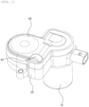
- FIG. 1 is a perspective view showing the configuration of a preferred embodiment of an actuator according to the present disclosure
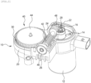
- FIG. 2 is a perspective view showing an open state of a cover of the actuator according to the present disclosure
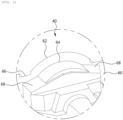
- FIG. 3 is an enlarged perspective view showing the configuration of a bearing mounting groove and a fusion guide surface formed on a lower surface of the cover constituting the embodiment of the present disclosure
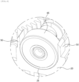
- FIG. 4 is an enlarged perspective view showing a state in which bearing fusion ribs are formed on both sides of a bearing insertion groove constituting the embodiment of the present disclosure
- FIG. 5 is an enlarged perspective view showing a state before the bearing fusion rib is fused to the outer circumferential surface of the bearing by laser irradiation constituting the embodiment of the present disclosure
- FIG. 6 is an enlarged cross-sectional view perspective view showing a state before the bearing fusion rib is fused to the outer circumferential surface of the bearing by laser irradiation constituting the embodiment of the present disclosure
- FIG. 7 is an enlarged cross-sectional view showing a state in which the bearing fusion rib is fused to the outer circumferential surface of the bearing by laser irradiation constituting the embodiment of the present disclosure.
- a bearing fixing structure of an actuator is characterized by including: a housing 10 provided with a motor receiving part 12 accommodating a motor 14 and a gear mounting part 20 on which a reduction gear unit 40 is mounted; a cover 50 coupled to an open upper portion of the housing 10 to close the upper portion of the housing 10; a worm gear 42 installed inside the gear mounting part 20 and installed in a direction orthogonal to a motor shaft 16 to transmit rotational power of the motor shaft 16; a bearing 46 installed on each side of the worm gear 42 and rotatably supporting the worm gear 42; a bearing insertion groove 54 recessed in an arc shape inside the cover 50, to which a portion of the bearing 46 is fixedly coupled; and a bearing fusion rib 50 that protrudes by a predetermined height on both sides of the bearing insertion groove 26 and supports both sides of an outer circumferential surface of the bearing 46.
- the bearing fusion rib 50 is characterized by being melted by laser irradiation during the assembly process of the housing
- the actuator according to the present disclosure generates a large rotational force by decelerating the driving of a motor and transmits it to the outside to function as an electronic brake.
- a reduction gear unit 40 along with a motor 14 is installed inside the actuator of the present disclosure.
- the reduction gear unit 40 described below refers to an overall structure composed of a plurality of gears.
- the actuator forms an entire external structure by combining a housing 10 and a cover 50.
- the housing 10 may be divided into a motor receiving part 12 and a gear mounting part 20.
- a motor 14 and a reduction gear unit 40 are all shielded, and only a connector (not shown) for power supply and a final output shaft (not shown) are exposed to the outside.
- a motor 14 is installed inside the motor receiving part 12, and a motor shaft 16 is connected to the motor 14.
- the motor shaft 16 is rotated through the driving force of the motor 14, and extends in the longitudinal direction of the motor receiving part 12 with respect to FIG. 2 .
- a first worm 18, which will be described later, is installed at the end of the motor shaft 16.
- the first worm 18 rotates together with the motor shaft 16 and transmits the driving force of the motor 14 to a worm gear 42, which will be described later.
- the first worm 18 is exposed to the outside only when a cover 50, which will be described later, is removed.
- a gear mounting part 20 is formed on the upper part of the motor receiving part 12.
- the gear mounting part 20 is coupled to the upper part of the motor receiving part 12 and extends in the lateral direction of the motor receiving part 12.
- a reduction gear unit 40 which will be described later, is accommodated in a portion extending in the lateral direction of the motor receiving part 12.
- the gear mounting part 20 may be assembled separately from the motor receiving part 12, or may be made integral with both.
- a receiving part 22 is formed on the upper surface of the gear mounting part 20.
- the receiving part 22 is an open portion on the upper surface of the gear mounting part 20 and is also a portion shielded by the cover 50.
- a reduction gear unit 40 which will be described later, is installed in the receiving part 22.
- the receiving part 22 has a first installation part 24 into which a worm gear 42, which will be described later, is installed, and a second installation part 30, into which a drive gear 44, which will be described later, is inserted. This will be explained again below.
- the first installation part 24 is formed in the receiving part 22.
- the first installation part 24 is a portion in which a worm gear 42 is seated among the reduction gear units 40, which will be described later.
- the first installation part 24 extends longitudinally in one direction and is recessed by a predetermined depth in an arc shape. Inside the first installation part 24, the worm gear 42, which will be described later, is inserted and rotatably mounted as shown in FIG. 2 .
- Bearing insertion grooves 26 and bush insertion grooves 28 are formed at both ends of the first installation part 24.
- the bearing insertion groove 26 and the bush insertion groove 28 are recessed by a predetermined depth in a semicircular shape. Inside the bearing insertion groove 26 and the bush insertion groove 28, a portion of the bearing 46 and the bush 48, which will be described later, are vertically inserted and fixed.
- a second receiving part 22 is formed on the left side of the first receiving part 22.
- the second receiving part 22 is formed to be recessed in a circular shape surrounding a drive gear 44, which will be described later.
- the drive gear 44 is inserted into the second installation part 30. Inside the second installation part 30, the drive gear 44, which will be described later, is rotatably installed.
- a reduction gear unit 40 is installed inside the first receiving part 22 and the second receiving part 22.
- the reduction gear unit 40 largely consists of a worm gear 42 and a drive gear 44.
- the worm gear 42 is a general worm gear, and detailed description will be omitted.
- the worm gear 42 is installed long forward and backward direction inside the first receiving part 22.
- One side of the worm gear 42 is gear-coupled to a first worm 18 of the motor shaft 16, and the other side of the worm gear 42 is gear-coupled to a drive gear 44, which will be described later.
- the worm gear 42 is rotatably installed inside the first receiving part 22 and serves to transmit the rotational power of the motor shaft 16 to the drive gear 44, which will be described later.
- the worm gear 42 is installed in a direction orthogonal to the motor shaft 16 to reduce and transmit the drive of the motor 14, but also serves to transmit the drive by changing the direction.
- a drive gear 44 is installed inside the second receiving part 22.
- the drive gear 44 is a general spur gear, and detailed description will be omitted.
- the drive gear 44 is gear-coupled to the worm gear 42 and is rotatably installed in the second receiving part 22 to transmit the reduced rotational power to the outside.
- Bearings 46 and bushes 48 are installed on each side of the worm gear 42.
- the bearing 46 is a general bearing and detailed description will be omitted.
- the bearing 46 is installed inside the bearing insertion groove 26 as shown in FIG. 2 and serves to rotatably support the worm gear 42.
- the bush 48 is installed on the opposite side of the bearing 46.
- the bush 48 is a general bush and detailed description will be omitted.
- the bush 48 is fixedly coupled to the end of the worm gear 42 and is inserted into the bush insertion groove 28 to rotatably support the worm gear 42.
- Bearing fusion ribs 50 are formed on both sides of the bearing insertion groove 26, respectively. As shown in FIG. 4 , the bearing fusion ribs 50 are formed to protrude vertically by a predetermined height from the left and right upper surfaces of the bearing insertion groove 26. When the bearing 46 is mounted on the bearing insertion groove 26, the bearing fusion ribs 50 are placed on both outer circumferential surfaces of the bearing 46 to support both outer circumferential surfaces of the bearing 46.
- the end of the bearing fusion rib 50 is formed to be inclined downward by a predetermined angle from an inner direction to an outer direction of the bearing 46 with respect to the bearing 46. As the end of the bearing fusion rib 50 is formed to be inclined downward, when the bearing fusion rib 50 is melted by laser irradiation and fused to the outer circumferential surface of the bearing, the bearing fusion rib 50 may be in close contact with the outer circumferential surface of the bearing 46 by a fusion guide surface 68, which will be described later.
- a cover 60 is installed on the upper side of the housing 10.
- the cover 60 is installed to cover the upper opening of the housing 10.
- the cover 60 is coupled and fixed to the upper end of the motor receiving part 12 and the gear mounting part 20.
- the cover 60 serves to close the upper end of the housing so that the motor shaft 16 and the reduction gear unit 40 are not exposed to the outside.
- a bearing mounting part 62 is protruding from one side of the upper surface of the cover 60.
- the bearing mounting part 62 has an arc shape and protrudes upward at a position corresponding to the bearing insertion groove 26. Inside the bearing mounting part 62, the upper part of the bearing 46 is inserted and fixed.
- a bearing mounting groove 64 is formed inside the bearing mounting part 62.
- the bearing mounting groove 64 is recessed in a semicircular shape inside the bearing mounting part 62. Inside the bearing mounting groove 64, the upper end of the bearing 46 is inserted and fixed.
- a laser guide groove 66 is formed at one side of the bearing mounting part 62. As shown in FIG. 5 , the laser guide groove 66 is shaped like a square box and is recessed by a predetermined depth. The laser guide groove 66 is formed at a position corresponding to the bearing fusion rib 50 and guides a laser to the bearing fusion rib 50 when the laser is irradiated to the cover 60.
- the laser irradiated to the cover 60 by the laser guide groove 66 may be irradiated adjacent to the bearing fusion rib 50, so that the melting or degradation of the bearing fusion rib 50 may be made smoother.
- Fusion guide surfaces 68 are formed on both sides of the bearing mounting groove 64. As shown in FIG. 3 , the fusion guide surface 68 extends along both ends of the bearing mounting groove 64, and is formed to be inclined downward at a predetermined angle from the inside to the outside with respect to the bearing mounting groove 64.
- the fusion guide surface 68 is located on the upper side of the bearing fusion rib 50.
- the fusion guide surface 68 is formed to incline downward from the inside to the outside with respect to the bearing mounting groove 64.
- the motor 14 and the reduction gear unit 40 are mounted inside the housing 10.
- the bearings 46 and the bushes 48 are mounted on both ends of the worm gear 42 of the reduction gear unit 40, and the bearings 26 and bushes 48 are inserted into the bearing insertion groove 26 and the bush insertion groove 28, respectively.
- the cover 60 is installed on the upper opening of the housing 10 in order to completely seal the inside of the actuator while the motor 14 and the reduction gear unit 40 are mounted inside the housing 10.
- the assembly process of the housing 10 and the cover 60 is performed by assembling the cover 60 from the upper side to the lower side of the housing 10, with the cover 60 positioned on the upper surface of the housing 10.
- the housing 10 and the cover 60 may be hermetically sealed by a laser fusion process.
- the fusion guide surface 68 of the cover 60 presses the bearing fusion rib 50.
- the bearing fusion rib 50 which supports both sides of the bearing 26, is degraded.
- the bearing fusion rib 50 is fused to the outer peripheral surface of the bearing 26 along the fusion guide surface 68, thereby forming the bearing 26 to be completely retained by the bearing fusion rib 50.
- the bearing fusion ribs 50 which support both sides of the bearing, are melted by laser irradiation and fused and fixed to the bearing 26. Accordingly, the bearing 46 may be completely retained and the shaking of the bearing 46 may be minimized.
- fusion guide surfaces 68 are formed on both sides of the bearing mounting groove 64. During the process of assembling the housing 10 and the cover 60 and fixing them by laser fusion, the fusion guide surface 68 guides the melted bearing fusion ribs 50 to the outer circumferential surface of the bearing 46, so that the bearing fusion ribs 50 may be firmly fused to the outer circumferential surface of the bearing 46.
- the laser guide groove 66 is formed on the upper surface of the cover 60, so when a laser is irradiated on the cover 60, the laser may be irradiated to a location adjacent to the bearing fusion rib 50, allowing the bearing fusion rib 50 to be melted more smoothly.
Landscapes
- Engineering & Computer Science (AREA)
- Mechanical Engineering (AREA)
- Transportation (AREA)
- General Engineering & Computer Science (AREA)
- Power Engineering (AREA)
- Mounting Of Bearings Or Others (AREA)
- Connection Of Motors, Electrical Generators, Mechanical Devices, And The Like (AREA)
Abstract
The present disclosure relates to a bearing fixing structure for an actuator, in which bearing fusion ribs (50) supporting both sides of a bearing (46) are melted by a laser irradiation and fused and fixed to an outer circumferential surface of the bearing (46), thereby achieving complete retention of the bearing (46).
Description
- The present application claims priority to
Korean Patent Application No. 10-2022-0168446, filed December 06, 2022 - The present disclosure relates to a bearing fixing structure for an actuator, in which bearing fusion ribs supporting both sides of a bearing are melted by a laser irradiation and fused and fixed to an outer circumferential surface of the bearing, thereby achieving complete retention of the bearing.
- Generally, an electronic actuator of a vehicle is intended to operate a friction pad installed on a caliper of a disc brake device during parking. An electronic parking brake operates automatically by a user's switch operation, and for this purpose it consists of an electronic parking brake motor and a gear assembly (power transmission device) to transmit the power of the motor.
- In this type of electronic parking brake, when the driver presses a parking brake switch, a rotational force of an actuator's motor is transmitted to the caliper's input shaft through the gear assembly (power transmission device) such as a decelerator. When the input shaft receiving power rotates, a pressurized connection sleeve moves forward, and a piston and a caliper housing accommodating the connection sleeve move toward each other as the connection sleeve advances. In addition, two friction pads mounted on the piston and caliper housing hold both sides of a disc against rotation to ensure parking.
- A conventional electronic parking brake actuator assembly is disclosed in
Korean Patent Publication No. 10-2020-0029587 - In a conventional actuator for a braking device, a worm gear is installed in a direction orthogonal to a motor shaft, and bearings and bushes (holders) are combined at both ends of the worm gear to be rotatable inside the housing.
- The bearings and bushes (holders) of these brake actuators may be installed and fixed in mounting grooves formed on a cover and a housing.
- However, as the bearing and bush (holder) are simply fixed in the mounting groove, the shaking of the bearing or bush (holder) may cause abnormal operation and failure of the actuator when vibration or shock occurs.
- In addition, the bearing or bush may be fixed to the mounting groove by applying an ultrasonic fusion method to prevent shaking of these bearings and bushes. However, in the case of the ultrasonic fusion method of these bearings or bushes, there is a problem that vibration may cause subtle distortion of the shaft (warm gear) or surface damage due to stress generation in the cover part.
- (Patent Document)
Korean Patent Publication No. 10-2020-0029587 - The object of the present disclosure is to solve the problems of the prior art as described above. In a bearing fixing structure of an actuator according to the present disclosure, as bearing fusion ribs, which support both sides of a bearing, are melted by a laser irradiation and fused and fixed to an outer circumferential surface of the bearing, complete retention of the bearing may be achieved.
- According to the characteristics of the present disclosure for achieving the above-described object, a bearing fixing structure of an actuator according to the present disclosure comprises: a housing provided with a motor receiving part for accommodating a motor and a gear mounting part on which a reduction gear unit is mounted; a cover coupled to an open upper portion of the housing to close the upper portion of the housing; a worm gear installed inside the gear mounting part and installed in a direction orthogonal to a motor shaft to transmit rotational power of the motor shaft; a bearing installed on each side of the worm gear and rotatably supporting the worm gear; a bearing insertion groove recessed in an arc shape inside the cover, to which a portion of the bearing is fixedly coupled; a bearing fusion rib that protrudes by a predetermined height on both sides of the bearing insertion groove and supports both sides of an outer circumferential surface of the bearing. The bearing fusion rib is melted by laser irradiation during the assembly process of the housing and the cover and is fused and fixed to the outer circumferential surface of the bearing.
- The lower surface of the cover is further provided with a fusion guide surface which is inclined at a predetermined angle at a position corresponding to the bearing fusion rib. When the cover is irradiated with a laser, in the process of assembling the housing and the cover, the bearing fusion rib is guided to be fused to the outer circumferential surface of the bearing by the fusion guide surface.
- The fusion guide surface is formed to be inclined downward the inner direction to the outer direction of the bearing.
- The upper surface of the cover is further provided with a laser guide groove which is recessed by a predetermined depth at a position corresponding to the bearing fusion rib and guides a laser toward the bearing fusion rib
- The bearing fusion rib is characterized in that the end is formed to be inclined downward from the inner direction to the outer direction of the bearing.
- A bearing fixing structure of an actuator according to the present disclosure has the following effects.
- As the bearing fusion ribs supporting both sides of the bearing are melted by a laser irradiation, and fused and fixed to the bearing, complete retention of the bearing may be achieved and there is an advantage of minimizing malfunction and failure of the actuator due to the bearing vibration.
- Additionally, fusion guide surfaces are formed on both sides of a bearing mounting groove. During the process of assembling a housing and a cover and fixing them by laser fusion, the fusion guide surface guides the melted bearing fusion ribs to the outer circumferential surface of the bearing, so that the bearing fusion ribs may be firmly fused to the outer circumferential surface of the bearing.
- In addition, the laser guide groove is formed on the upper surface of the cover, so when a laser is irradiated on the cover, the laser may be irradiated to a location adjacent to the bearing fusion rib, allowing the bearing fusion rib to be melted more smoothly.
-
-
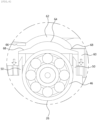
FIG. 1 is a perspective view showing the configuration of a preferred embodiment of an actuator according to the present disclosure. -
FIG. 2 is a perspective view showing an open state of a cover of the actuator according to the present disclosure. -
FIG. 3 is an enlarged perspective view showing the configuration of a bearing mounting groove and a fusion guide surface formed on a lower surface of the cover constituting the embodiment of the present disclosure. -
FIG. 4 is an enlarged perspective view showing a state in which bearing fusion ribs are formed on both sides of a bearing insertion groove constituting the embodiment of the present disclosure. -
FIG. 5 is an enlarged perspective view showing a state before the bearing fusion rib is fused to an outer circumferential surface of the bearing by laser irradiation constituting the embodiment of the present disclosure. -
FIG. 6 is an enlarged cross-sectional view perspective view showing a state before the bearing fusion rib is fused to an outer circumferential surface of the bearing by laser irradiation constituting the embodiment of the present disclosure. -
FIG. 7 is an enlarged cross-sectional view showing a state in which the bearing fusion rib is fused to an outer circumferential surface of the bearing by laser irradiation constituting the embodiment of the present disclosure. - Hereinafter, a preferred embodiment of a bearing fixing structure of an actuator according to the present disclosure will be described in detail with reference to the attached drawings.
-
FIG. 1 is a perspective view showing the configuration of a preferred embodiment of an actuator according to the present disclosure,FIG. 2 is a perspective view showing an open state of a cover of the actuator according to the present disclosure,FIG. 3 is an enlarged perspective view showing the configuration of a bearing mounting groove and a fusion guide surface formed on a lower surface of the cover constituting the embodiment of the present disclosure,FIG. 4 is an enlarged perspective view showing a state in which bearing fusion ribs are formed on both sides of a bearing insertion groove constituting the embodiment of the present disclosure,FIG. 5 is an enlarged perspective view showing a state before the bearing fusion rib is fused to the outer circumferential surface of the bearing by laser irradiation constituting the embodiment of the present disclosure,FIG. 6 is an enlarged cross-sectional view perspective view showing a state before the bearing fusion rib is fused to the outer circumferential surface of the bearing by laser irradiation constituting the embodiment of the present disclosure, andFIG. 7 is an enlarged cross-sectional view showing a state in which the bearing fusion rib is fused to the outer circumferential surface of the bearing by laser irradiation constituting the embodiment of the present disclosure. - As shown in the drawings, a bearing fixing structure of an actuator according to the present disclosure is characterized by including: a
housing 10 provided with amotor receiving part 12 accommodating amotor 14 and agear mounting part 20 on which areduction gear unit 40 is mounted; acover 50 coupled to an open upper portion of thehousing 10 to close the upper portion of thehousing 10; aworm gear 42 installed inside thegear mounting part 20 and installed in a direction orthogonal to amotor shaft 16 to transmit rotational power of themotor shaft 16; abearing 46 installed on each side of theworm gear 42 and rotatably supporting theworm gear 42; a bearing insertion groove 54 recessed in an arc shape inside thecover 50, to which a portion of thebearing 46 is fixedly coupled; and abearing fusion rib 50 that protrudes by a predetermined height on both sides of thebearing insertion groove 26 and supports both sides of an outer circumferential surface of thebearing 46. Thebearing fusion rib 50 is characterized by being melted by laser irradiation during the assembly process of thehousing 10 and thecover 60 and being fused and fixed to the outer circumferential surface of thebearing 46. - The actuator according to the present disclosure generates a large rotational force by decelerating the driving of a motor and transmits it to the outside to function as an electronic brake. For this purpose, a
reduction gear unit 40 along with amotor 14 is installed inside the actuator of the present disclosure. Thereduction gear unit 40 described below refers to an overall structure composed of a plurality of gears. - First, looking at
FIGS. 1 and2 , the actuator forms an entire external structure by combining ahousing 10 and acover 50. Here, thehousing 10 may be divided into amotor receiving part 12 and agear mounting part 20. When thehousing 10 and thecover 50 are combined, amotor 14 and areduction gear unit 40 are all shielded, and only a connector (not shown) for power supply and a final output shaft (not shown) are exposed to the outside. - A
motor 14 is installed inside themotor receiving part 12, and amotor shaft 16 is connected to themotor 14. Themotor shaft 16 is rotated through the driving force of themotor 14, and extends in the longitudinal direction of themotor receiving part 12 with respect toFIG. 2 . A first worm 18, which will be described later, is installed at the end of themotor shaft 16. The first worm 18 rotates together with themotor shaft 16 and transmits the driving force of themotor 14 to aworm gear 42, which will be described later. As shown inFIG. 2 , the first worm 18 is exposed to the outside only when acover 50, which will be described later, is removed. - A
gear mounting part 20 is formed on the upper part of themotor receiving part 12. Thegear mounting part 20 is coupled to the upper part of themotor receiving part 12 and extends in the lateral direction of themotor receiving part 12. Areduction gear unit 40, which will be described later, is accommodated in a portion extending in the lateral direction of themotor receiving part 12. Thegear mounting part 20 may be assembled separately from themotor receiving part 12, or may be made integral with both. - A receiving
part 22 is formed on the upper surface of thegear mounting part 20. Thereceiving part 22 is an open portion on the upper surface of thegear mounting part 20 and is also a portion shielded by thecover 50. Areduction gear unit 40, which will be described later, is installed in the receivingpart 22. For this purpose, the receivingpart 22 has afirst installation part 24 into which aworm gear 42, which will be described later, is installed, and asecond installation part 30, into which adrive gear 44, which will be described later, is inserted. This will be explained again below. - The
first installation part 24 is formed in the receivingpart 22. Thefirst installation part 24 is a portion in which aworm gear 42 is seated among thereduction gear units 40, which will be described later. Thefirst installation part 24 extends longitudinally in one direction and is recessed by a predetermined depth in an arc shape. Inside thefirst installation part 24, theworm gear 42, which will be described later, is inserted and rotatably mounted as shown inFIG. 2 . -
Bearing insertion grooves 26 andbush insertion grooves 28 are formed at both ends of thefirst installation part 24. - As shown in
FIG. 2 , the bearinginsertion groove 26 and thebush insertion groove 28 are recessed by a predetermined depth in a semicircular shape. Inside the bearinginsertion groove 26 and thebush insertion groove 28, a portion of thebearing 46 and thebush 48, which will be described later, are vertically inserted and fixed. - A second receiving
part 22 is formed on the left side of the first receivingpart 22. The second receivingpart 22 is formed to be recessed in a circular shape surrounding adrive gear 44, which will be described later. Thedrive gear 44 is inserted into thesecond installation part 30. Inside thesecond installation part 30, thedrive gear 44, which will be described later, is rotatably installed. - A
reduction gear unit 40 is installed inside the first receivingpart 22 and the second receivingpart 22. Thereduction gear unit 40 largely consists of aworm gear 42 and adrive gear 44. - The
worm gear 42 is a general worm gear, and detailed description will be omitted. Theworm gear 42 is installed long forward and backward direction inside the first receivingpart 22. One side of theworm gear 42 is gear-coupled to a first worm 18 of themotor shaft 16, and the other side of theworm gear 42 is gear-coupled to adrive gear 44, which will be described later. Theworm gear 42 is rotatably installed inside the first receivingpart 22 and serves to transmit the rotational power of themotor shaft 16 to thedrive gear 44, which will be described later. - In addition, the
worm gear 42 is installed in a direction orthogonal to themotor shaft 16 to reduce and transmit the drive of themotor 14, but also serves to transmit the drive by changing the direction. - A
drive gear 44 is installed inside the second receivingpart 22. Thedrive gear 44 is a general spur gear, and detailed description will be omitted. Thedrive gear 44 is gear-coupled to theworm gear 42 and is rotatably installed in the second receivingpart 22 to transmit the reduced rotational power to the outside. -
Bearings 46 andbushes 48 are installed on each side of theworm gear 42. Thebearing 46 is a general bearing and detailed description will be omitted. Thebearing 46 is installed inside the bearinginsertion groove 26 as shown inFIG. 2 and serves to rotatably support theworm gear 42. - The
bush 48 is installed on the opposite side of thebearing 46. Thebush 48 is a general bush and detailed description will be omitted. Thebush 48 is fixedly coupled to the end of theworm gear 42 and is inserted into thebush insertion groove 28 to rotatably support theworm gear 42. -
Bearing fusion ribs 50 are formed on both sides of the bearinginsertion groove 26, respectively. As shown inFIG. 4 , the bearingfusion ribs 50 are formed to protrude vertically by a predetermined height from the left and right upper surfaces of the bearinginsertion groove 26. When thebearing 46 is mounted on the bearinginsertion groove 26, the bearingfusion ribs 50 are placed on both outer circumferential surfaces of thebearing 46 to support both outer circumferential surfaces of thebearing 46. - The end of the bearing
fusion rib 50 is formed to be inclined downward by a predetermined angle from an inner direction to an outer direction of the bearing 46 with respect to thebearing 46. As the end of the bearingfusion rib 50 is formed to be inclined downward, when the bearingfusion rib 50 is melted by laser irradiation and fused to the outer circumferential surface of the bearing, the bearingfusion rib 50 may be in close contact with the outer circumferential surface of thebearing 46 by afusion guide surface 68, which will be described later. - A
cover 60 is installed on the upper side of thehousing 10. Thecover 60 is installed to cover the upper opening of thehousing 10. Thecover 60 is coupled and fixed to the upper end of themotor receiving part 12 and thegear mounting part 20. Thecover 60 serves to close the upper end of the housing so that themotor shaft 16 and thereduction gear unit 40 are not exposed to the outside. - A
bearing mounting part 62 is protruding from one side of the upper surface of thecover 60. Thebearing mounting part 62 has an arc shape and protrudes upward at a position corresponding to the bearinginsertion groove 26. Inside thebearing mounting part 62, the upper part of thebearing 46 is inserted and fixed. - A
bearing mounting groove 64 is formed inside thebearing mounting part 62. Thebearing mounting groove 64 is recessed in a semicircular shape inside thebearing mounting part 62. Inside thebearing mounting groove 64, the upper end of thebearing 46 is inserted and fixed. - A
laser guide groove 66 is formed at one side of thebearing mounting part 62. As shown inFIG. 5 , thelaser guide groove 66 is shaped like a square box and is recessed by a predetermined depth. Thelaser guide groove 66 is formed at a position corresponding to the bearingfusion rib 50 and guides a laser to the bearingfusion rib 50 when the laser is irradiated to thecover 60. - That is, the laser irradiated to the
cover 60 by thelaser guide groove 66 may be irradiated adjacent to the bearingfusion rib 50, so that the melting or degradation of the bearingfusion rib 50 may be made smoother. - Fusion guide surfaces 68 are formed on both sides of the
bearing mounting groove 64. As shown inFIG. 3 , thefusion guide surface 68 extends along both ends of thebearing mounting groove 64, and is formed to be inclined downward at a predetermined angle from the inside to the outside with respect to thebearing mounting groove 64. - The
fusion guide surface 68 is located on the upper side of the bearingfusion rib 50. When thehousing 10 and thecover 60 are assembled and laser fused, the bearingfusion rib 50 is pressed to guide the bearingfusion rib 50 to be fused to the outer circumferential surface of thebearing 26. - That is, the
fusion guide surface 68 is formed to incline downward from the inside to the outside with respect to thebearing mounting groove 64. During assembly and laser fusion of thehousing 10 and thecover 60, by guiding the meltedbearing fusion rib 50 toward thebearing 26, the bearing 26 may be completely retained by fusion to the bearingfusion rib 50. - Hereinafter, referring to
FIGS. 1 to 7 , the process in which thebearing fusion rib 50 is fused to the outer peripheral surface of the bearing 26 during assembly and laser fusion of thehousing 10 and thecover 60 will be described. - The
motor 14 and thereduction gear unit 40 are mounted inside thehousing 10. Thebearings 46 and thebushes 48 are mounted on both ends of theworm gear 42 of thereduction gear unit 40, and thebearings 26 andbushes 48 are inserted into the bearinginsertion groove 26 and thebush insertion groove 28, respectively. - The
cover 60 is installed on the upper opening of thehousing 10 in order to completely seal the inside of the actuator while themotor 14 and thereduction gear unit 40 are mounted inside thehousing 10. - The assembly process of the
housing 10 and thecover 60 is performed by assembling thecover 60 from the upper side to the lower side of thehousing 10, with thecover 60 positioned on the upper surface of thehousing 10. - When the
cover 60 is assembled to thehousing 10, thehousing 10 and thecover 60 may be hermetically sealed by a laser fusion process. - In the process of assembling the
cover 60 to thehousing 10, thefusion guide surface 68 of thecover 60 presses the bearingfusion rib 50. At the same time, as the laser is irradiated to thecover 60, the bearingfusion rib 50, which supports both sides of thebearing 26, is degraded. - In addition, while the bearing
fusion rib 50 is melted by laser irradiation, the bearingfusion rib 50 is fused to the outer peripheral surface of thebearing 26 along thefusion guide surface 68, thereby forming thebearing 26 to be completely retained by the bearingfusion rib 50. - According to the present disclosure, in the bearing fixing structure of the actuator, the bearing
fusion ribs 50, which support both sides of the bearing, are melted by laser irradiation and fused and fixed to thebearing 26. Accordingly, the bearing 46 may be completely retained and the shaking of thebearing 46 may be minimized. - Additionally, fusion guide surfaces 68 are formed on both sides of the
bearing mounting groove 64. During the process of assembling thehousing 10 and thecover 60 and fixing them by laser fusion, thefusion guide surface 68 guides the meltedbearing fusion ribs 50 to the outer circumferential surface of thebearing 46, so that the bearingfusion ribs 50 may be firmly fused to the outer circumferential surface of thebearing 46. - In addition, the
laser guide groove 66 is formed on the upper surface of thecover 60, so when a laser is irradiated on thecover 60, the laser may be irradiated to a location adjacent to the bearingfusion rib 50, allowing the bearingfusion rib 50 to be melted more smoothly. - The scope of the present disclosure is not limited to the embodiments illustrated above, and many other modifications based on the present disclosure will be possible to those skilled in the art within the above technical scope.
-
10 housing 12 motor receiving part 14 motor 16 motor shaft 18 first worm 22. receiving part 24. first installation part 26. bearing insertion groove 28. bush insertion groove 30. second installation part 40 reduction gear unit 42 worm gear 44. drive gear 46 bearing 48. bush 50 bearing fusion rib 60 cover 62. bearing mounting part 64 bearing mounting groove 66. laser guide groove 68 fusion guide surface
Claims (5)
- A bearing fixing structure of an actuator comprising:a housing (10) provided with a motor receiving part (12) accommodating a motor (14) and a gear mounting part (20) on which a reduction gear unit (40) is mounted;a cover (60) coupled to an open upper portion of the housing (10) to close the upper portion of the housing (10);a worm gear (42) installed inside the gear mounting part (20) and installed in a direction orthogonal to a motor shaft (16) to transmit rotational power of the motor shaft (16);a bearing (46) installed on each side of the worm gear (42) and rotatably supporting the worm gear (42);a bearing insertion groove (26) formed on one surface of the gear mounting part (20) by a predetermined depth, and into which a portion of the bearing (46) is inserted and fixed; anda bearing fusion rib (50) protruding from both sides of the bearing insertion groove (26) by a predetermined height and supporting both sides of an outer circumferential surface of the bearing (46),characterized in that the bearing fusion rib (50) is melted by laser irradiation during an assembly process of the housing (10) and the cover (60), and is fused and fixed to the outer circumferential surface of the bearing (46).
- The bearing fixing structure of the actuator of claim 1, further comprising a fusion guide surface (68) provided on a lower surface of the cover (60), the fusion guide surface (68) being inclined at a predetermined angle at a position corresponding to the bearing fusion rib (50),
characterized in that when the cover (60) is irradiated with a laser, the fusion guide surface (68) guides the bearing fusion rib (50) to be fused to the outer circumferential surface of the bearing (46) in the process of assembling the housing (10) and the cover (60). - The bearing fixing structure of the actuator of claim 2, characterized in that the fusion guide surface (68) is formed to be inclined downward from the inner direction to the outer direction of the bearing (46).
- The bearing fixing structure of the actuator of claim 3, further comprising a laser guide groove (66),
characterized in that the laser guide groove (66) is formed to be recessed to a predetermined depth on the upper surface of the cover (60) at a position corresponding to the bearing fusion rib (50), and guides the laser toward the bearing fusion rib (50). - The bearing fixing structure of the actuator of claim 3, characterized in that the bearing fusion rib (50) has an end formed to be inclined downward from the inner direction to the outer direction of the bearing (46).
Applications Claiming Priority (1)
| Application Number | Priority Date | Filing Date | Title |
|---|---|---|---|
| KR1020220168446A KR102827908B1 (en) | 2022-12-06 | 2022-12-06 | Actuator With Bearing Fixture |
Publications (1)
| Publication Number | Publication Date |
|---|---|
| EP4382376A1 true EP4382376A1 (en) | 2024-06-12 |
Family
ID=88978182
Family Applications (1)
| Application Number | Title | Priority Date | Filing Date |
|---|---|---|---|
| EP23212688.8A Withdrawn EP4382376A1 (en) | 2022-12-06 | 2023-11-28 | A bearing fixing structure for an actuator |
Country Status (2)
| Country | Link |
|---|---|
| EP (1) | EP4382376A1 (en) |
| KR (1) | KR102827908B1 (en) |
Citations (4)
| Publication number | Priority date | Publication date | Assignee | Title |
|---|---|---|---|---|
| KR20180126107A (en) * | 2017-05-16 | 2018-11-27 | 주식회사 유니크 | Actuator for electronic parking brake |
| KR20200029587A (en) | 2017-08-02 | 2020-03-18 | 닛산 지도우샤 가부시키가이샤 | Driving support method and driving support device |
| US20220017057A1 (en) * | 2018-12-12 | 2022-01-20 | Keyang Electric Machinery Co., Ltd. | Electronic parking brake actuator assembly |
| US20220379866A1 (en) * | 2019-11-12 | 2022-12-01 | Mando Corporation | Actuator for brake device |
Family Cites Families (3)
| Publication number | Priority date | Publication date | Assignee | Title |
|---|---|---|---|---|
| JP2008216121A (en) * | 2007-03-06 | 2008-09-18 | Konica Minolta Opto Inc | Method for manufacturing microchip |
| KR101484459B1 (en) * | 2012-11-08 | 2015-02-10 | 동아하이테크 주식회사 | Change speed actuator |
| KR101727012B1 (en) * | 2015-01-28 | 2017-04-14 | 캄텍주식회사 | An actuator for a vechicle |
-
2022
- 2022-12-06 KR KR1020220168446A patent/KR102827908B1/en active Active
-
2023
- 2023-11-28 EP EP23212688.8A patent/EP4382376A1/en not_active Withdrawn
Patent Citations (4)
| Publication number | Priority date | Publication date | Assignee | Title |
|---|---|---|---|---|
| KR20180126107A (en) * | 2017-05-16 | 2018-11-27 | 주식회사 유니크 | Actuator for electronic parking brake |
| KR20200029587A (en) | 2017-08-02 | 2020-03-18 | 닛산 지도우샤 가부시키가이샤 | Driving support method and driving support device |
| US20220017057A1 (en) * | 2018-12-12 | 2022-01-20 | Keyang Electric Machinery Co., Ltd. | Electronic parking brake actuator assembly |
| US20220379866A1 (en) * | 2019-11-12 | 2022-12-01 | Mando Corporation | Actuator for brake device |
Also Published As
| Publication number | Publication date |
|---|---|
| KR20240084547A (en) | 2024-06-13 |
| KR102827908B1 (en) | 2025-07-02 |
Similar Documents
| Publication | Publication Date | Title |
|---|---|---|
| CN108458004B (en) | Electronic disc brake | |
| KR102174273B1 (en) | An actuator assembly for electromechanical parking brake | |
| US20250249880A1 (en) | Actuator for brake device | |
| EP4382376A1 (en) | A bearing fixing structure for an actuator | |
| CN102762883B (en) | Electric brake device for vehicle | |
| JP2019009998A (en) | motor | |
| KR101930763B1 (en) | Actuator for electronic parking brake | |
| KR20210026164A (en) | Actuator for brake device | |
| EP4382760A1 (en) | A bearing fixing structure for an actuator | |
| KR101779830B1 (en) | Gear fixing structure of MOC actuator gear box | |
| KR20210000083A (en) | Actuator for vehicle | |
| KR101609091B1 (en) | An actuator of motor cover integrated with gear box | |
| JP7413950B2 (en) | gear device | |
| JP7723241B2 (en) | Vehicle sliding window panel opening and closing device | |
| KR101950235B1 (en) | Actuator for electronic parking brake | |
| JP3595187B2 (en) | Actuator | |
| KR101612668B1 (en) | An actuator with shock-absorbing fixed structure | |
| JPS6146258B2 (en) | ||
| CN111594614A (en) | Novel parking mechanism and vehicle | |
| EP4582715A1 (en) | Brake device and vehicle including the same | |
| CN219709748U (en) | Differential adjusting mechanism and sewing machine with same | |
| KR20210000084A (en) | Actuator for vehicle | |
| KR102922292B1 (en) | Disc brake and planetary gear reduction mechanism | |
| KR20240088273A (en) | Brake device | |
| JP2000291763A (en) | Actuator |
Legal Events
| Date | Code | Title | Description |
|---|---|---|---|
| PUAI | Public reference made under article 153(3) epc to a published international application that has entered the european phase |
Free format text: ORIGINAL CODE: 0009012 |
|
| STAA | Information on the status of an ep patent application or granted ep patent |
Free format text: STATUS: REQUEST FOR EXAMINATION WAS MADE |
|
| 17P | Request for examination filed |
Effective date: 20231128 |
|
| AK | Designated contracting states |
Kind code of ref document: A1 Designated state(s): AL AT BE BG CH CY CZ DE DK EE ES FI FR GB GR HR HU IE IS IT LI LT LU LV MC ME MK MT NL NO PL PT RO RS SE SI SK SM TR |
|
| STAA | Information on the status of an ep patent application or granted ep patent |
Free format text: STATUS: THE APPLICATION IS DEEMED TO BE WITHDRAWN |
|
| 18D | Application deemed to be withdrawn |
Effective date: 20241213 |