EP4379130B1 - Stoffauflauf und verfahren zum auftragen von beschichtungszusammensetzungen auf ein bewegendes nasspulpesubstrat unter verwendung dieses stoffauflaufs - Google Patents
Stoffauflauf und verfahren zum auftragen von beschichtungszusammensetzungen auf ein bewegendes nasspulpesubstrat unter verwendung dieses stoffauflaufs Download PDFInfo
- Publication number
- EP4379130B1 EP4379130B1 EP22210936.5A EP22210936A EP4379130B1 EP 4379130 B1 EP4379130 B1 EP 4379130B1 EP 22210936 A EP22210936 A EP 22210936A EP 4379130 B1 EP4379130 B1 EP 4379130B1
- Authority
- EP
- European Patent Office
- Prior art keywords
- coating composition
- headbox
- valve body
- stream
- chamber
- Prior art date
- Legal status (The legal status is an assumption and is not a legal conclusion. Google has not performed a legal analysis and makes no representation as to the accuracy of the status listed.)
- Active
Links
Images

Classifications
-
- D—TEXTILES; PAPER
- D21—PAPER-MAKING; PRODUCTION OF CELLULOSE
- D21F—PAPER-MAKING MACHINES; METHODS OF PRODUCING PAPER THEREON
- D21F1/00—Wet end of machines for making continuous webs of paper
- D21F1/02—Head boxes of Fourdrinier machines
- D21F1/026—Details of the turbulence section
-
- D—TEXTILES; PAPER
- D21—PAPER-MAKING; PRODUCTION OF CELLULOSE
- D21F—PAPER-MAKING MACHINES; METHODS OF PRODUCING PAPER THEREON
- D21F1/00—Wet end of machines for making continuous webs of paper
- D21F1/02—Head boxes of Fourdrinier machines
- D21F1/028—Details of the nozzle section
-
- D—TEXTILES; PAPER
- D21—PAPER-MAKING; PRODUCTION OF CELLULOSE
- D21H—PULP COMPOSITIONS; PREPARATION THEREOF NOT COVERED BY SUBCLASSES D21C OR D21D; IMPREGNATING OR COATING OF PAPER; TREATMENT OF FINISHED PAPER NOT COVERED BY CLASS B31 OR SUBCLASS D21G; PAPER NOT OTHERWISE PROVIDED FOR
- D21H23/00—Processes or apparatus for adding material to the pulp or to the paper
- D21H23/02—Processes or apparatus for adding material to the pulp or to the paper characterised by the manner in which substances are added
- D21H23/04—Addition to the pulp; After-treatment of added substances in the pulp
- D21H23/06—Controlling the addition
- D21H23/14—Controlling the addition by selecting point of addition or time of contact between components
-
- D—TEXTILES; PAPER
- D21—PAPER-MAKING; PRODUCTION OF CELLULOSE
- D21H—PULP COMPOSITIONS; PREPARATION THEREOF NOT COVERED BY SUBCLASSES D21C OR D21D; IMPREGNATING OR COATING OF PAPER; TREATMENT OF FINISHED PAPER NOT COVERED BY CLASS B31 OR SUBCLASS D21G; PAPER NOT OTHERWISE PROVIDED FOR
- D21H23/00—Processes or apparatus for adding material to the pulp or to the paper
- D21H23/02—Processes or apparatus for adding material to the pulp or to the paper characterised by the manner in which substances are added
- D21H23/22—Addition to the formed paper
- D21H23/24—Addition to the formed paper during paper manufacture
- D21H23/26—Addition to the formed paper during paper manufacture by selecting point of addition or moisture content of the paper
Definitions
- the present invention relates to the field of paper machines, in general, and in particular to a headbox, such as a secondary headbox, for applying a coating composition onto a moving wet pulp substrate in a paper machine, as well as a method of applying a coating composition onto a moving wet pulp substrate in a paper machine equipped with such a headbox, a paper machine comprising such a headbox as well as the use of such a headbox in a method of applying a horizontal stream of a coating composition onto a horizontally moving wet pulp substrate in a paper machine.
- a headbox such as a secondary headbox
- Paper machines use a moving woven mesh, also known as wire, to create a continuous paper web by filtering out the fibres held in a wet paper stock and producing a continuously moving wet mat of fibre.
- the wet paper stock is dispensed onto the wire mesh from a so-called headbox.
- the headbox essentially holds the wet paper stock and must, on one hand, keep the fibers from clumping together by generating turbulence in its interior, and on the other hand, uniformly distribute the wet paper stock across the width of the wire. Fulfilling both requirements ensures the formation of a homogenous mat of wet pulp on the wire.
- Such a homogenous layer will in any case depend on multiple factors, such as matching of the speed at which the coating composition contacts the moving wet pulp layer from the primary headbox to the speed of the moving wet pulp layer, as well adjusting the angle at which the coating composition contacts the moving wet pulp layer from the primary headbox, all the while warranting that the flow rate, width, thickness, rheology and consistency of the coating composition exiting the secondary head box is on-target.
- the present invention provides for a headbox design that is capable of providing a stream, such as for example a curtain, of a coating composition onto a moving wet pulp substrate in a paper machine that results in the formation of a coating layer on the wet pulp substrate that is homogenous in thickness and width.
- the headbox design of the present invention is particularly suited for coating compositions having a particular rheology profile, such as for example coating compositions comprising microfibrillated cellulose. It has further been found that the design of the headbox provides excellent rigidity, or less bending propensity, which leads to a more homogenous coating on the moving wet pulp substrate.
- It is a second object of the present invention to provide a paper machine comprising a primary headbox for forming a wet pulp substrate and secondary headbox according to first object of the present invention for applying a stream, or jet, of a coating composition onto a moving wet pulp substrate.
- a headbox (1) for a paper machine in particular a secondary headbox for applying a stream of, preferably a jet of, a coating composition onto a moving wet pulp substrate in a paper machine, comprising
- the ratio (d 1 /d 2 ) between distance d 1 and distance d 2 is more than 1, preferably is between 1 and 3 and/or the distance d 2 is between 0.4 and 20 mm, preferably between 0.4 and 10 mm, more preferably between 0.8 and 3 mm. 1.
- (d 1 /d 2 ) between distance d 1 and distance d 2 is constant, and is preferably about 2.
- the headbox (1) according to the present invention is preferably a secondary headbox for applying a stream of a coating composition onto a moving wet pulp substrate in a paper machine, which wet pulp substrate is formed by dispensing a stock made of water, paper pulp and suitable additives from a primary headbox onto the moving wire mesh of the paper machine in the wet end of the paper machine.
- the stock from which the wet pulp substrate is formed may comprise one or more pulps, preferably wood pulps, which may further be chemical wood pulps such as for example sulphite pulp or kraft pulp.
- the chemical wood pulps may further be bleached chemical wood pulps.
- the coating composition upon being forced through the first larger clearance, is accelerated and exposed to a first amount of shear, and when forced through the second clearance, is further accelerated and exposed to a second amount of shear.
- the consecutive acceleration and/or shearing leads to a decrease in viscosity which enables the coating composition to be coated homogenously onto the moving wet pulp substrate.
- the stream of a coating composition can be applied onto a moving wet pulp substrate in a paper machine according to the second object such that the stream of a coating composition contacting the moving wet pulp substrate contacts the moving wet pulp substrate at an angle of between 3 and 75°, preferably of 15 to 40°.
- Controlling the angle at which a coating composition can be applied onto a moving wet pulp substrate can be useful when adjusting the degree of shear that is imparted on the coating composition immediately after contacting the moving wet pulp substrate. At smaller angles, the lateral shear is minimized, as the stream of a coating composition gets barely deflected whereas at larger angles, the stream of a coating composition gets deflected significantly in the direction of the moving wet pulp substrate.
- the length of the falling stream of a coating composition is between 3 mm and 500 mm.
- the length of the falling stream of a coating composition corresponds to the distance between the point where the stream leaves the bottom lip (11) extending from the slice chamber (4) to the point where the stream of a coating composition contacts the moving wet pulp substrate.
- the speed of the stream of a coating composition is in the range of 50 to 700 m/min or may be in the range of 50 to 1200 m/min.
- the coating composition comprises microfibrillated cellulose.
- the coating composition is an aqueous suspension of microfibrillated cellulose.
- the microfibrillated cellulose may be comprised in an amount of less than 2.5 weight percent, based on the total weight of the coating composition, more preferably in an amount of from 0.5 to 2.0 weight percent, even more preferably in an amount of 0.8 to 1.0 weight percent.
- the microfibrillated cellulose is preferably microfibrillated cellulose made from hardwood.
- coating compositions comprising microfibrillated cellulose are a prominent example of coating compositions that can be applied with the headbox (1) according to the present invention, and in the method of applying a stream of a coating composition onto a moving wet pulp substrate in a paper machine according to the present invention
- other coating compositions that may be applied are coating compositions that, in general, are shear-thinning and/or which have a viscosity of about 5 to 100 mPas when under shear rate of about 1000 to 8000 s -1 , when measured according to ISO 3219 on a Physica Anton Paar MCR 300 using spindle CC27 SN4989 and cup CC27 SS43953.
- the moving wet pulp substrate has a solids content of less than 20% by weight, about 4 to 20%, preferably of 4 to 8% by weight, based on the total weight of the moving wet pulp substrate.
- the remaining weight is formed by at least 80% by weight of aqueous liquids such as water. It is believed that since the water content in the moving wet pulp substrate is high, an entanglement between the loosened wet pulp substrate fibers and the microfibrillated fibers of the coating composition is thereby enhanced, and therefore results in better adhesion between these layers in the final paper product.
- a coating composition comprising microfibrillated cellulose at about 8 g/l was prepared and provided to a headbox (1) according to the present invention via feeding lines placed along the longitudinal dimension of the headbox (1) (i.e. transverse paper machine direction), and fed to the stock chamber (2) of the headbox (1) at about a pressure of 51 kPa.
- the headbox (1) was then opened by an angle of 14 °, such as to provide a jet having a thickness of 1.4 mm and of a width of 1000 mm, at a flow rate of 840 I/min per meter width of the second clearance of the headbox (1).
- the angle of the headbox (1) with respect to the plane of the moving wet substrate was about 12° and the headbox (1) was positioned at about 5mm above the moving wet substrate.
- the velocity of the moving wet substrate and the velocity of the jet exiting the headbox (1) was 10 m/s and 10,08 m/s, respectively.
- the moving wet substrate was prepared by discharging a stock having a consistency of about 10 g/l of a chemical wood pulp having refining degree more than 90 °SR
- the weight of the coating composition on the moving wet substrate was checked by online measuring of the freshly deposited coating composition and found to be homogenous across the entire width, and to be about 14 gr/m 2 .
Landscapes
- Paper (AREA)
Claims (21)
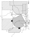
- Stoffauflaufkasten (1) für eine Papiermaschine, insbesondere ein Sekundärstoffauflaufkasten zum Aufbringen eines Strahls einer Beschichtungszusammensetzung auf ein sich bewegendes nasses Zellstoffsubstrat in einer Papiermaschine, umfassend- eine Vorratsbütte (2)- eine Beruhigungskammer (3)- eine Austrittsspaltkammer (4)- eine Ventilanordnung zum Steuern des Stroms der Beschichtungszusammensetzung von der Vorratsbütte (2) in die Beruhigungskammer (3) und zum Steuern des Stroms der Beschichtungszusammensetzung von der Beruhigungskammer (3) zur Austrittsspaltkammer (4) wobei die Ventilanordnung einen drehbaren Ventilkörper (5) und einen Ventilgehäusekörper (6) umfasst, wobei der drehbare Ventilkörper (5) innerhalb des Ventilgehäusekörpers (6) angeordnet ist,wobei der drehbare Ventilkörper (5) in einen geschlossenen Zustand und in einen oder mehrere geöffnete Zustände drehbar ist,wobei der drehbare Ventilkörper (5) ein erstes und ein zweites Dichtelement (7, 8) und der Ventilgehäusekörper (6) eine erste und eine zweite Dichtfläche (9, 10) umfasst,wobei in einem geschlossenen Zustanda. das erste Dichtelement (7) in dichtendem Kontakt mit einer ersten Dichtfläche (9) am Ventilgehäusekörper (6) steht und dadurch eine erste Dichtung bildet, die die Vorratsbütte (2) von der Beruhigungskammer (3) abdichtet, und/oderb. das zweite Dichtelement (8) in dichtendem Kontakt mit einer zweiten Dichtfläche (10) am Ventilgehäusekörper (6) steht und dadurch eine zweite Dichtung bildet, die die Beruhigungskammer (3) gegenüber der Austrittsspaltkammer (4) abdichtet,wobei in einem offenen Zustanda. das erste Dichtelement (7) sich in einem ersten Abstand d1 von der ersten Dichtfläche (9) am Ventilgehäusekörper (6) befindet, wodurch ein erster Durchgang gebildet wird und die Vorratsbütte (2) mit der Beruhigungskammer (3) fluidisch verbunden wird, undb. das zweite Dichtelement (8) sich in einem zweiten Abstand d2 von der zweiten Dichtfläche (10) am Ventilgehäusekörper (6) befindet, wodurch ein zweiter Durchgang gebildet wird und die Beruhigungskammer (3) mit der Austrittsspaltkammer (4) fluidisch verbunden wird, undwobei beim Drehen des drehbaren Ventilkörpers (5) von einem offenen Zustand in den geschlossenen Zustand das erste und das zweite Dichtelement (7, 8) gleichzeitig entlang einer Kreisbahn in dichtenden Kontakt mit einer ersten und einer zweiten Dichtfläche (9, 10) bewegt werden,wobei beim Drehen des drehbaren Ventilkörpers (5) von einem geschlossenen Zustand in den geöffneten Zustand das erste und das zweite Dichtelement (7, 8) gleichzeitig entlang einer Kreisbahn C von einer ersten und zweiten Dichtfläche (9, 10) wegbewegt werden,und wobei in jedem offenen Zustand der erste Abstand größer ist als der zweite Abstand.
- Stoffauflaufkasten nach Anspruch 1, wobei der erste Durchgang um einen Faktor von mehr als 1 und bis zu 3 größer ist als der zweite Durchgang.
- Stoffauflaufkasten gemäß Anspruch 1 oder 2, wobei der Stoffauflaufkasten (1) als Ganzes drehbar ist, um die Richtung des Stroms der Beschichtungszusammensetzung zu ändern, die die Austrittsspaltkammer (4) verlässt, und/oder wobei der Stoffauflaufkasten (1) als Ganzes in eine oder mehrere Richtungen beweglich ist, vorzugsweise zumindest in eine Richtung senkrecht zur Ebene des sich bewegenden nassen Zellstoffsubstrats, um die Richtung des Stroms der Beschichtungszusammensetzung zu ändern, die mit dem sich bewegenden nassen Zellstoffsubstrat in einer Papiermaschine in Kontakt kommt, wobei sich das sich bewegende nasse Zellstoffsubstrat vorzugsweise in horizontaler Richtung bewegt.
- Stoffauflaufkasten nach einem der vorhergehenden Ansprüche, wobei der drehbare Ventilkörper (5) eine Welle ist und/oder wobei der drehbare Ventilkörper (5) um eine Längsachse (A) des drehbaren Ventilkörpers (5) drehbar ist.
- Stoffauflaufkasten nach einem der vorhergehenden Ansprüche, wobei der drehbare Ventilkörper (5) eine Achse umfasst, die sich entlang einer Längsachse (A) des drehbaren Ventilkörpers (5) erstreckt, wobei die Achse mit einem steuerbaren Drehantriebsmittel gekoppelt ist, um den drehbaren Ventilkörper (5) zu drehen.
- Stoffauflaufkasten nach einem der vorhergehenden Ansprüche, wobei der drehbare Ventilkörper (5) eine oder mehrere Stangen umfasst, die über ein Gelenk mit einem Umfang des drehbaren Ventilkörpers (5) verbunden sind, wobei die Stange mit einem steuerbaren linearen Antriebsmittel gekoppelt ist, um den drehbaren Ventilkörper (5) zu drehen.
- Stoffauflaufkasten nach einem der vorhergehenden Ansprüche, wobei die ersten und/oder zweiten Dichtelemente (7, 8) durch Dichtrippen gebildet sind, insbesondere durch Dichtrippen, die sich vorzugsweise geradlinig parallel zu einer Längsachse (A) des drehbaren Ventilkörpers (5) erstrecken, wobei die Rippen vorzugsweise eine abgerundete, quadratische oder spitze Spitze aufweisen.
- Stoffauflaufkasten nach einem der vorhergehenden Ansprüche, wobei sich der drehbare Ventilkörper (5) im geöffneten Zustand in einem Drehwinkel α von bis zu 40° befindet und/oder sich der drehbare Ventilkörper (5) im geschlossenen Zustand in einem Drehwinkel α von 0° befindet.
- Stoffauflaufkasten nach einem der vorhergehenden Ansprüche, wobei der drehbare Ventilkörper (5) eine teilweise kreisförmige Querschnittsform aufweist, wobei der kreisförmige Abschnitt der Querschnittsform des drehbaren Ventilkörpers (5) gleitend in dichtendem Kontakt mit einer oder zwei Dichtungen steht.
- Stoffauflaufkasten nach einem der vorhergehenden Ansprüche, wobei der drehbare Ventilkörper (5) eine Welle ist und wobei der drehbare Ventilkörper (5) entlang einer Längsachse (A) der Welle drehbar ist, wobei sich das erste und das zweite Dichtungselement (7, 8) im gleichen radialen Abstand von der Längsachse (A) der Welle befinden.
- Stoffauflaufkasten nach einem der vorhergehenden Ansprüche, wobei die erste Dichtfläche (9) eine konvexe Fläche des Ventilgehäusekörpers (6) ist, wobei die konvexe Fläche vorzugsweise eine kreisförmige Form aufweist, und/oder die zweite Dichtfläche (10) eine ebene Fläche des Ventilgehäusekörpers (6) ist.
- Stoffauflaufkasten nach einem der vorhergehenden Ansprüche, wobei die Beruhigungskammer (3) eine konkave Oberfläche umfasst, die zwischen der ersten Dichtfläche (9) und der zweiten Dichtfläche (10) angeordnet ist.
- Stoffauflaufkasten nach einem der vorhergehenden Ansprüche, wobei der zwischen der Beruhigungskammer (3) und der Austrittsspaltkammer (4) gebildete Durchgang die Form eines horizontalen rechteckigen Schlitzes zum Ausstoßen des Stroms einer Beschichtungszusammensetzung aus der Austrittsspaltkammer (4) hat, wobei die Höhe des horizontalen Schlitzes 0,3 bis 5 mm, vorzugsweise 0,8 mm bis 3 mm beträgt.
- Stoffauflaufkasten nach einem der vorhergehenden Ansprüche, wobei die Austrittsspaltkammer (4) an ihrem stromabwärtigen Ende eine Unterlippe (11) zum Leiten des aus der Austrittsspaltkammer (4) austretenden Stroms einer Beschichtungszusammensetzung aufweist, und wobei die Unterlippe (11) vorzugsweise eine Unterlippe (11) mit variabler Länge ist.
- Eine Papiermaschine, die einen Primärstoffauflaufkasten zum Bilden eines nassen Zellstoffsubstrats und einen Sekundärstoffauflaufkasten gemäß einem der Ansprüche 1 bis 14 zum Aufbringen eines Stroms einer Beschichtungszusammensetzung auf ein sich bewegendes nasses Zellstoffsubstrat umfasst.
- Verfahren zum Aufbringen eines Stroms einer Beschichtungszusammensetzung auf ein sich bewegendes nasses Zellstoffsubstrat in einer Papiermaschine, wobei der Strom der Beschichtungszusammensetzung die Austrittsspaltkammer (4) eines Stoffauflaufkastens gemäß einem der Ansprüche 1 bis 14 in ihrem offenen Zustand verlässt, und wobei das Verhältnis der Geschwindigkeiten des Stroms der Beschichtungszusammensetzung V1 und des sich bewegenden nassen Zellstoffsubstrats V2 zwischen 0,9 und 1,1 liegt.
- Verfahren zum Aufbringen eines Stroms einer Beschichtungszusammensetzung auf ein sich bewegendes nasses Zellstoffsubstrat in einer Papiermaschine gemäß Anspruch 16, wobei der Strom einer Beschichtungszusammensetzung, der mit dem sich bewegenden nassen Zellstoffsubstrat in Kontakt kommt, das sich bewegende nasse Zellstoffsubstrat in einem Winkel zwischen 3 und 75° berührt.
- Verfahren zum Aufbringen eines Stroms einer Beschichtungszusammensetzung auf ein sich bewegendes nasses Zellstoffsubstrat in einer Papiermaschine gemäß Anspruch 16 oder 17, wobei die Länge des fallenden Stroms einer Beschichtungszusammensetzung zwischen 3 mm und 500 mm liegt und/oder wobei die Strömungsrate des Stroms einer Beschichtungszusammensetzung im Bereich von 50 bis 4000 l/min pro Meter Breite des zweiten Durchgangs liegt.
- Verfahren zum Aufbringen eines Stroms einer Beschichtungszusammensetzung auf ein sich bewegendes nasses Zellstoffsubstrat in einer Papiermaschine gemäß einem der Ansprüche 16 bis 18, wobei das nasse Zellstoffsubstrat einen Feststoffgehalt von weniger als 20 Gewichtsprozent oder von etwa 4 bis 20 Gewichtsprozent, vorzugsweise von etwa 4 bis 8 Gewichtsprozent aufweist.
- Verfahren zum Aufbringen eines Stroms einer Beschichtungszusammensetzung auf ein sich bewegendes nasses Zellstoffsubstrat in einer Papiermaschine gemäß einem der Ansprüche 16 bis 19, wobei die Beschichtungszusammensetzung mikrofibrillierte Zellulose umfasst, vorzugsweise eine wässrige Suspension von mikrofibrillierter Zellulose ist, und wobei die Beschichtungszusammensetzung die mikrofibrillierte Zellulose noch bevorzugter in einer Menge von weniger als 2,5 Gewichtsprozent, basierend auf dem Gesamtgewicht der Beschichtungszusammensetzung, umfasst, noch bevorzugter in einer Menge von 0,5 bis 2,0 Gewichtsprozent.
- Verwendung eines Stoffauflaufkastens nach einem der Ansprüche 1 bis 14 in einem Verfahren zum Aufbringen eines horizontalen Stroms einer Beschichtungszusammensetzung auf ein sich horizontal bewegendes nasses Zellstoffsubstrat in einer Papiermaschine, vorzugsweise in einem Verfahren nach einem der Ansprüche 16 bis 20, wobei der horizontale Strom einer Beschichtungszusammensetzung die Austrittsspaltkammer des Stoffauflaufkastens nach einem der Ansprüche 1 bis 14 in ihrem offenen Zustand mit einer horizontalen Geschwindigkeit (V1) verlässt und wobei das Verhältnis der horizontalen Geschwindigkeiten des horizontalen Stroms einer Beschichtungszusammensetzung und des sich horizontal bewegenden nassen Zellstoffsubstrats (V2) zwischen 0,9 und 1,1 liegt
Priority Applications (3)
| Application Number | Priority Date | Filing Date | Title |
|---|---|---|---|
| ES22210936T ES3035469T3 (en) | 2022-12-01 | 2022-12-01 | Headbox and method for applying coating compositions onto a moving wet pulp substrate using said headbox |
| EP22210936.5A EP4379130B1 (de) | 2022-12-01 | 2022-12-01 | Stoffauflauf und verfahren zum auftragen von beschichtungszusammensetzungen auf ein bewegendes nasspulpesubstrat unter verwendung dieses stoffauflaufs |
| PCT/EP2023/083624 WO2024115610A1 (en) | 2022-12-01 | 2023-11-29 | Headbox and method for applying coating compositions onto a moving wet pulp substrate using said headbox |
Applications Claiming Priority (1)
| Application Number | Priority Date | Filing Date | Title |
|---|---|---|---|
| EP22210936.5A EP4379130B1 (de) | 2022-12-01 | 2022-12-01 | Stoffauflauf und verfahren zum auftragen von beschichtungszusammensetzungen auf ein bewegendes nasspulpesubstrat unter verwendung dieses stoffauflaufs |
Publications (3)
| Publication Number | Publication Date |
|---|---|
| EP4379130A1 EP4379130A1 (de) | 2024-06-05 |
| EP4379130B1 true EP4379130B1 (de) | 2025-07-02 |
| EP4379130C0 EP4379130C0 (de) | 2025-07-02 |
Family
ID=84369784
Family Applications (1)
| Application Number | Title | Priority Date | Filing Date |
|---|---|---|---|
| EP22210936.5A Active EP4379130B1 (de) | 2022-12-01 | 2022-12-01 | Stoffauflauf und verfahren zum auftragen von beschichtungszusammensetzungen auf ein bewegendes nasspulpesubstrat unter verwendung dieses stoffauflaufs |
Country Status (3)
| Country | Link |
|---|---|
| EP (1) | EP4379130B1 (de) |
| ES (1) | ES3035469T3 (de) |
| WO (1) | WO2024115610A1 (de) |
Family Cites Families (2)
| Publication number | Priority date | Publication date | Assignee | Title |
|---|---|---|---|---|
| US5104011A (en) * | 1990-08-03 | 1992-04-14 | Ingersoll-Rand Company | Self-cleaning feed apparatus |
| US5456804A (en) * | 1994-08-22 | 1995-10-10 | Ingersoll-Rand Company | Inlet slice assembly, for a pulp slurry processing machine |
-
2022
- 2022-12-01 EP EP22210936.5A patent/EP4379130B1/de active Active
- 2022-12-01 ES ES22210936T patent/ES3035469T3/es active Active
-
2023
- 2023-11-29 WO PCT/EP2023/083624 patent/WO2024115610A1/en not_active Ceased
Also Published As
| Publication number | Publication date |
|---|---|
| ES3035469T3 (en) | 2025-09-03 |
| EP4379130A1 (de) | 2024-06-05 |
| EP4379130C0 (de) | 2025-07-02 |
| WO2024115610A1 (en) | 2024-06-06 |
Similar Documents
| Publication | Publication Date | Title |
|---|---|---|
| CN100354472C (zh) | 用于向卷筒纸添加材料的方法和装置 | |
| CA2492641C (en) | A cigarette paper | |
| US5645689A (en) | Multilayer headbox | |
| US5447753A (en) | Method of manufacturing coated paper for printing | |
| US4945855A (en) | Coater | |
| US10550520B2 (en) | Method with a horizontal jet applicator for a paper machine wet end | |
| EP3830336B1 (de) | Verfahren und vorrichtung zur stärkeanwendung | |
| US20110083603A1 (en) | Curtain coater | |
| US20240424519A1 (en) | Application nozzle, application unit and method | |
| ZA201005687B (en) | Curtain coater | |
| EP2784213B1 (de) | Stoffauflauf für eine Maschine zur Herstellung einer Faserstoffbahn | |
| JPH03161599A (ja) | ロールコータ、ロールコータの使用方法、ロールコータ用デッケル | |
| EP4379130B1 (de) | Stoffauflauf und verfahren zum auftragen von beschichtungszusammensetzungen auf ein bewegendes nasspulpesubstrat unter verwendung dieses stoffauflaufs | |
| JP2011508833A (ja) | 移動オリフィスを用いてスリット帯状包装紙を作る方法及び装置 | |
| CN117306307B (zh) | 用于平整和涂覆涂覆介质的设备 | |
| WO2009063135A1 (en) | A method for feeding high-consistency pulp to a formation support and a high-consistency pulp headbox | |
| US5824369A (en) | Method and apparatus for coating a traveling paper web | |
| CA2248892C (en) | Reverse feed film applicator | |
| DE102023106574A1 (de) | Auftragsdüse, Former und Verwendung | |
| EP2894254B1 (de) | Beschichtungsvorrichtung zum Auftragen von Lackfarbe auf ein Fasergewebe und Verfahren zur Beschichtung eines Fasergewebes | |
| EP4245916A1 (de) | Verfahren zur behandlung einer faserstoffbahn und behandlungssystem zur behandlung einer faserstoffbahn | |
| US20240131549A1 (en) | Casting device, system and method of casting an mfc film | |
| US5914155A (en) | Method and applicator for direct or indirect application of a liquid or pasty coating medium onto a traveling material web, notably of paper or cardboard | |
| CN213408280U (zh) | 在用于纤维幅材的表面胶的生产中的浆料容器 | |
| EP3540117B1 (de) | Mehrschichtiger stoffauflauf für eine maschine zur herstellung einer faserstoffbahn und verfahren zur bidung einer faserstoffbahn in einer formierpartie einer maschine zur herstellung einer faserstoffbahn |
Legal Events
| Date | Code | Title | Description |
|---|---|---|---|
| PUAI | Public reference made under article 153(3) epc to a published international application that has entered the european phase |
Free format text: ORIGINAL CODE: 0009012 |
|
| STAA | Information on the status of an ep patent application or granted ep patent |
Free format text: STATUS: THE APPLICATION HAS BEEN PUBLISHED |
|
| AK | Designated contracting states |
Kind code of ref document: A1 Designated state(s): AL AT BE BG CH CY CZ DE DK EE ES FI FR GB GR HR HU IE IS IT LI LT LU LV MC ME MK MT NL NO PL PT RO RS SE SI SK SM TR |
|
| STAA | Information on the status of an ep patent application or granted ep patent |
Free format text: STATUS: REQUEST FOR EXAMINATION WAS MADE |
|
| 17P | Request for examination filed |
Effective date: 20240829 |
|
| RBV | Designated contracting states (corrected) |
Designated state(s): AL AT BE BG CH CY CZ DE DK EE ES FI FR GB GR HR HU IE IS IT LI LT LU LV MC ME MK MT NL NO PL PT RO RS SE SI SK SM TR |
|
| GRAP | Despatch of communication of intention to grant a patent |
Free format text: ORIGINAL CODE: EPIDOSNIGR1 |
|
| STAA | Information on the status of an ep patent application or granted ep patent |
Free format text: STATUS: GRANT OF PATENT IS INTENDED |
|
| RIC1 | Information provided on ipc code assigned before grant |
Ipc: D21H 23/26 20060101ALI20250120BHEP Ipc: D21H 23/14 20060101ALI20250120BHEP Ipc: D21H 23/24 20060101ALI20250120BHEP Ipc: D21F 1/02 20060101AFI20250120BHEP |
|
| INTG | Intention to grant announced |
Effective date: 20250129 |
|
| GRAS | Grant fee paid |
Free format text: ORIGINAL CODE: EPIDOSNIGR3 |
|
| GRAA | (expected) grant |
Free format text: ORIGINAL CODE: 0009210 |
|
| STAA | Information on the status of an ep patent application or granted ep patent |
Free format text: STATUS: THE PATENT HAS BEEN GRANTED |
|
| AK | Designated contracting states |
Kind code of ref document: B1 Designated state(s): AL AT BE BG CH CY CZ DE DK EE ES FI FR GB GR HR HU IE IS IT LI LT LU LV MC ME MK MT NL NO PL PT RO RS SE SI SK SM TR |
|
| RAP1 | Party data changed (applicant data changed or rights of an application transferred) |
Owner name: SAPPI PAPIER HOLDING GMBH |
|
| REG | Reference to a national code |
Ref country code: GB Ref legal event code: FG4D |
|
| REG | Reference to a national code |
Ref country code: CH Ref legal event code: EP |
|
| REG | Reference to a national code |
Ref country code: DE Ref legal event code: R096 Ref document number: 602022016814 Country of ref document: DE |
|
| REG | Reference to a national code |
Ref country code: IE Ref legal event code: FG4D |
|
| U01 | Request for unitary effect filed |
Effective date: 20250707 |
|
| U07 | Unitary effect registered |
Designated state(s): AT BE BG DE DK EE FI FR IT LT LU LV MT NL PT RO SE SI Effective date: 20250711 |
|
| REG | Reference to a national code |
Ref country code: ES Ref legal event code: FG2A Ref document number: 3035469 Country of ref document: ES Kind code of ref document: T3 Effective date: 20250903 |
|
| PG25 | Lapsed in a contracting state [announced via postgrant information from national office to epo] |
Ref country code: IS Free format text: LAPSE BECAUSE OF FAILURE TO SUBMIT A TRANSLATION OF THE DESCRIPTION OR TO PAY THE FEE WITHIN THE PRESCRIBED TIME-LIMIT Effective date: 20251102 |
|
| PG25 | Lapsed in a contracting state [announced via postgrant information from national office to epo] |
Ref country code: NO Free format text: LAPSE BECAUSE OF FAILURE TO SUBMIT A TRANSLATION OF THE DESCRIPTION OR TO PAY THE FEE WITHIN THE PRESCRIBED TIME-LIMIT Effective date: 20251002 |
|
| U20 | Renewal fee for the european patent with unitary effect paid |
Year of fee payment: 4 Effective date: 20251211 |
|
| PG25 | Lapsed in a contracting state [announced via postgrant information from national office to epo] |
Ref country code: HR Free format text: LAPSE BECAUSE OF FAILURE TO SUBMIT A TRANSLATION OF THE DESCRIPTION OR TO PAY THE FEE WITHIN THE PRESCRIBED TIME-LIMIT Effective date: 20250702 |
|
| PG25 | Lapsed in a contracting state [announced via postgrant information from national office to epo] |
Ref country code: GR Free format text: LAPSE BECAUSE OF FAILURE TO SUBMIT A TRANSLATION OF THE DESCRIPTION OR TO PAY THE FEE WITHIN THE PRESCRIBED TIME-LIMIT Effective date: 20251003 |
|
| PGFP | Annual fee paid to national office [announced via postgrant information from national office to epo] |
Ref country code: TR Payment date: 20251125 Year of fee payment: 4 |
|
| PG25 | Lapsed in a contracting state [announced via postgrant information from national office to epo] |
Ref country code: CZ Free format text: LAPSE BECAUSE OF FAILURE TO SUBMIT A TRANSLATION OF THE DESCRIPTION OR TO PAY THE FEE WITHIN THE PRESCRIBED TIME-LIMIT Effective date: 20250702 |
|
| PG25 | Lapsed in a contracting state [announced via postgrant information from national office to epo] |
Ref country code: PL Free format text: LAPSE BECAUSE OF FAILURE TO SUBMIT A TRANSLATION OF THE DESCRIPTION OR TO PAY THE FEE WITHIN THE PRESCRIBED TIME-LIMIT Effective date: 20250702 |
|
| PG25 | Lapsed in a contracting state [announced via postgrant information from national office to epo] |
Ref country code: RS Free format text: LAPSE BECAUSE OF FAILURE TO SUBMIT A TRANSLATION OF THE DESCRIPTION OR TO PAY THE FEE WITHIN THE PRESCRIBED TIME-LIMIT Effective date: 20251002 |