EP4378342A1 - Basis oder laufteil für ein schuhwerk sowie schuhe, die dieselbe komponente enthalten - Google Patents
Basis oder laufteil für ein schuhwerk sowie schuhe, die dieselbe komponente enthalten Download PDFInfo
- Publication number
- EP4378342A1 EP4378342A1 EP23212738.1A EP23212738A EP4378342A1 EP 4378342 A1 EP4378342 A1 EP 4378342A1 EP 23212738 A EP23212738 A EP 23212738A EP 4378342 A1 EP4378342 A1 EP 4378342A1
- Authority
- EP
- European Patent Office
- Prior art keywords
- base
- casing
- main plate
- tread component
- footwear
- Prior art date
- Legal status (The legal status is an assumption and is not a legal conclusion. Google has not performed a legal analysis and makes no representation as to the accuracy of the status listed.)
- Pending
Links
- 239000004433 Thermoplastic polyurethane Substances 0.000 claims abstract description 23
- 229920002803 thermoplastic polyurethane Polymers 0.000 claims abstract description 23
- 238000000465 moulding Methods 0.000 claims abstract description 18
- 238000000034 method Methods 0.000 claims description 18
- 239000011344 liquid material Substances 0.000 claims description 8
- 239000011343 solid material Substances 0.000 claims description 8
- 239000000463 material Substances 0.000 description 18
- 210000002683 foot Anatomy 0.000 description 14
- 239000004814 polyurethane Substances 0.000 description 11
- 238000002347 injection Methods 0.000 description 10
- 239000007924 injection Substances 0.000 description 10
- 229920002635 polyurethane Polymers 0.000 description 10
- 238000013461 design Methods 0.000 description 4
- 238000004519 manufacturing process Methods 0.000 description 4
- 230000008569 process Effects 0.000 description 4
- 230000001681 protective effect Effects 0.000 description 4
- 239000007787 solid Substances 0.000 description 4
- 230000006378 damage Effects 0.000 description 3
- 238000011161 development Methods 0.000 description 3
- 238000001746 injection moulding Methods 0.000 description 3
- 230000001788 irregular Effects 0.000 description 3
- 239000007788 liquid Substances 0.000 description 3
- 229920003023 plastic Polymers 0.000 description 3
- 239000004033 plastic Substances 0.000 description 3
- 210000003371 toe Anatomy 0.000 description 3
- 208000008035 Back Pain Diseases 0.000 description 2
- 206010061218 Inflammation Diseases 0.000 description 2
- 208000002193 Pain Diseases 0.000 description 2
- 238000005299 abrasion Methods 0.000 description 2
- 238000010521 absorption reaction Methods 0.000 description 2
- 239000003086 colorant Substances 0.000 description 2
- 238000010276 construction Methods 0.000 description 2
- 230000007423 decrease Effects 0.000 description 2
- 230000003247 decreasing effect Effects 0.000 description 2
- 239000006185 dispersion Substances 0.000 description 2
- 229920001971 elastomer Polymers 0.000 description 2
- 230000004054 inflammatory process Effects 0.000 description 2
- 230000007257 malfunction Effects 0.000 description 2
- 239000002184 metal Substances 0.000 description 2
- 230000007935 neutral effect Effects 0.000 description 2
- 229920000642 polymer Polymers 0.000 description 2
- 239000000243 solution Substances 0.000 description 2
- 208000004067 Flatfoot Diseases 0.000 description 1
- 241000233866 Fungi Species 0.000 description 1
- 206010020649 Hyperkeratosis Diseases 0.000 description 1
- 229920000271 Kevlar® Polymers 0.000 description 1
- 208000007702 Metatarsalgia Diseases 0.000 description 1
- 206010028391 Musculoskeletal Pain Diseases 0.000 description 1
- 229920000459 Nitrile rubber Polymers 0.000 description 1
- 208000010332 Plantar Fasciitis Diseases 0.000 description 1
- 229910000831 Steel Inorganic materials 0.000 description 1
- 238000004026 adhesive bonding Methods 0.000 description 1
- 230000004075 alteration Effects 0.000 description 1
- 230000001458 anti-acid effect Effects 0.000 description 1
- 239000010426 asphalt Substances 0.000 description 1
- 230000015572 biosynthetic process Effects 0.000 description 1
- 230000008859 change Effects 0.000 description 1
- 239000003795 chemical substances by application Substances 0.000 description 1
- 230000000295 complement effect Effects 0.000 description 1
- 239000002131 composite material Substances 0.000 description 1
- 230000002354 daily effect Effects 0.000 description 1
- 230000001419 dependent effect Effects 0.000 description 1
- 208000037265 diseases, disorders, signs and symptoms Diseases 0.000 description 1
- 208000035475 disorder Diseases 0.000 description 1
- 230000004064 dysfunction Effects 0.000 description 1
- 230000000694 effects Effects 0.000 description 1
- -1 even loose Substances 0.000 description 1
- 230000003203 everyday effect Effects 0.000 description 1
- 239000003292 glue Substances 0.000 description 1
- 230000036541 health Effects 0.000 description 1
- 230000005802 health problem Effects 0.000 description 1
- 208000007427 heel spur Diseases 0.000 description 1
- 230000006872 improvement Effects 0.000 description 1
- 238000003780 insertion Methods 0.000 description 1
- 230000037431 insertion Effects 0.000 description 1
- 230000007794 irritation Effects 0.000 description 1
- 239000012948 isocyanate Substances 0.000 description 1
- 150000002513 isocyanates Chemical class 0.000 description 1
- 239000004761 kevlar Substances 0.000 description 1
- 210000003127 knee Anatomy 0.000 description 1
- 230000002045 lasting effect Effects 0.000 description 1
- 230000003902 lesion Effects 0.000 description 1
- 230000005923 long-lasting effect Effects 0.000 description 1
- 239000011159 matrix material Substances 0.000 description 1
- 230000010198 maturation time Effects 0.000 description 1
- 239000012528 membrane Substances 0.000 description 1
- 238000012986 modification Methods 0.000 description 1
- 230000004048 modification Effects 0.000 description 1
- 230000007170 pathology Effects 0.000 description 1
- 230000000149 penetrating effect Effects 0.000 description 1
- 230000021715 photosynthesis, light harvesting Effects 0.000 description 1
- 229920001200 poly(ethylene-vinyl acetate) Polymers 0.000 description 1
- 229920005862 polyol Polymers 0.000 description 1
- 150000003077 polyols Chemical class 0.000 description 1
- 229920003225 polyurethane elastomer Polymers 0.000 description 1
- 230000002035 prolonged effect Effects 0.000 description 1
- 230000001105 regulatory effect Effects 0.000 description 1
- 239000012779 reinforcing material Substances 0.000 description 1
- 230000000284 resting effect Effects 0.000 description 1
- 230000035939 shock Effects 0.000 description 1
- 238000007711 solidification Methods 0.000 description 1
- 230000008023 solidification Effects 0.000 description 1
- 239000010959 steel Substances 0.000 description 1
- 238000012360 testing method Methods 0.000 description 1
- 239000002699 waste material Substances 0.000 description 1
- 230000036642 wellbeing Effects 0.000 description 1
Images





Classifications
-
- A—HUMAN NECESSITIES
- A43—FOOTWEAR
- A43B—CHARACTERISTIC FEATURES OF FOOTWEAR; PARTS OF FOOTWEAR
- A43B7/00—Footwear with health or hygienic arrangements
- A43B7/14—Footwear with health or hygienic arrangements with foot-supporting parts
- A43B7/1405—Footwear with health or hygienic arrangements with foot-supporting parts with pads or holes on one or more locations, or having an anatomical or curved form
- A43B7/1415—Footwear with health or hygienic arrangements with foot-supporting parts with pads or holes on one or more locations, or having an anatomical or curved form characterised by the location under the foot
- A43B7/144—Footwear with health or hygienic arrangements with foot-supporting parts with pads or holes on one or more locations, or having an anatomical or curved form characterised by the location under the foot situated under the heel, i.e. the calcaneus bone
-
- A—HUMAN NECESSITIES
- A43—FOOTWEAR
- A43B—CHARACTERISTIC FEATURES OF FOOTWEAR; PARTS OF FOOTWEAR
- A43B13/00—Soles; Sole-and-heel integral units
- A43B13/02—Soles; Sole-and-heel integral units characterised by the material
- A43B13/12—Soles with several layers of different materials
- A43B13/122—Soles with several layers of different materials characterised by the outsole or external layer
-
- A—HUMAN NECESSITIES
- A43—FOOTWEAR
- A43B—CHARACTERISTIC FEATURES OF FOOTWEAR; PARTS OF FOOTWEAR
- A43B13/00—Soles; Sole-and-heel integral units
- A43B13/14—Soles; Sole-and-heel integral units characterised by the constructive form
- A43B13/18—Resilient soles
- A43B13/181—Resiliency achieved by the structure of the sole
-
- A—HUMAN NECESSITIES
- A43—FOOTWEAR
- A43B—CHARACTERISTIC FEATURES OF FOOTWEAR; PARTS OF FOOTWEAR
- A43B13/00—Soles; Sole-and-heel integral units
- A43B13/14—Soles; Sole-and-heel integral units characterised by the constructive form
- A43B13/18—Resilient soles
- A43B13/181—Resiliency achieved by the structure of the sole
- A43B13/186—Differential cushioning region, e.g. cushioning located under the ball of the foot
-
- A—HUMAN NECESSITIES
- A43—FOOTWEAR
- A43B—CHARACTERISTIC FEATURES OF FOOTWEAR; PARTS OF FOOTWEAR
- A43B21/00—Heels; Top-pieces or top-lifts
- A43B21/24—Heels; Top-pieces or top-lifts characterised by the constructive form
- A43B21/26—Resilient heels
-
- B—PERFORMING OPERATIONS; TRANSPORTING
- B29—WORKING OF PLASTICS; WORKING OF SUBSTANCES IN A PLASTIC STATE IN GENERAL
- B29D—PRODUCING PARTICULAR ARTICLES FROM PLASTICS OR FROM SUBSTANCES IN A PLASTIC STATE
- B29D35/00—Producing footwear
- B29D35/06—Producing footwear having soles or heels formed and joined on to preformed uppers using a moulding technique, e.g. by injection moulding, pressing and vulcanising
Definitions
- the present invention concerns a base or tread component for a footwear as well as a footwear including the same component, in particular for use as work footwear or as personal protective equipment (PPE).
- PPE personal protective equipment
- Safety footwear are used by many categories of workers, such as bricklayers, gardeners, painters, machine and construction site operators, and by many other types of workers.
- This safety device has been widely used not only on construction sites, as initially happened, but also in all situations in which there may be a risk for the feet, such as restaurant kitchens or laboratories of various kinds.
- the sole of the footwear can be reinforced to protect the lower part of the foot from possible injuries caused by nails or other sharp objects, but these measures are not sufficient, as the rigid reinforcing material prevents the natural and correct movement of the foot.
- the sole of work footwear is subject to certification and, in particular, must be anti-abrasion, anti-oil, anti-acid, anti-slip and anti-static.
- the materials used to make the soles of work footwear are compact polyurethane and nitrile rubber.
- the latter properly treated, protects HRO certified footwear, which resist heat (by contact) up to 300° C and are used for example by asphalt workers and welders.
- tread design it is designed to give maximum stability and grip to the sole in difficult situations.
- Unsuitable or deteriorated footwear that is not replaced promptly can cause alterations in the normal functions of the foot, and therefore can cause disorders and inflammatory reactions.
- the feet are in fact subjected to a condition of pressure in footwear for many hours during a normal working day, so many workers complain of pain and inflammation due precisely to the use of safety footwear.
- the main foot pathologies that can develop over time are: heel pain, metatarsalgia, heel spurs, plantar fasciitis, talalgia, to name a few.
- Prolonged use of these footwear can also cause osteoarticular pain, calluses and blisters, fungus on the toes due to poor perspiration, irritation or slight lesions on the skin, incorrect posture and back pain.
- the weight of the footwear has decreased and the shape has also been partially softened thanks to the adoption of materials such as Kevlar, which is much lighter than steel, but performs the same protective tasks.
- safety footwear is made according to two main methods.
- a first method consists in the application of the sole or gluing and requires that the soles and uppers are made separately and then glued with specific glues.
- the soles in question can be made of rubber, TPU, EVA and contain inserts and elements inside them designed to disperse energy. These products are typical of the sporting world since they can use materials that do not have to comply with safety standards, and do not have to maintain regular performance for long continuous periods of use.
- a second method concerns footwear made by direct injection onto the upper and is carried out by injection molding which involves the injection of a molten (plasticized) plastic material at high pressure inside a closed mold, which is opened after the solidification of the object.
- polyol and isocyanate are conveyed onto an injection screw where they are mixed, so as to react and form polyurethane, which, pushed into the mold, solidifies forming the midsole which inextricably welds the tread (which can be in rubber, TPU, TR, or polyurethane) to the upper, generating a long-lasting and high-performance product over time.
- the main purpose of the present invention is to improve the state of the art in the footwear sector, in particular in work or safety footwear.
- Another object of the present invention is to provide a base or tread component for a footwear or a footwear owing to which it is possible to use any insert with rebounding capacity.
- Yet another object of the present invention is to allow the use of a wide range of materials for a respective insert.
- Another object of the present invention is to provide a footwear which combines increased comfort with a system integrated into the footwear itself which eliminates or significantly reduces the risks of breakage or malfunction.
- a base or tread component for footwear in particular a work or safety footwear, according to claim 1.
- a footwear in particular a work or safety footwear, according to claim 14.
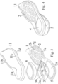
- the present invention concerns a base or tread component 1 for a footwear, for example a work or safety footwear, which base or tread component 1 includes a main plate element 2 made of thermoplastic polyurethane (TPU).
- TPU thermoplastic polyurethane
- the base or tread component 1 then comprises a casing or wrapping element 3 made by molding, preferably by injection, of thermoplastic polyurethane (TPU) on an upper rear portion 2a of the main plate element 2.
- TPU thermoplastic polyurethane
- the casing or wrapping element 3, or rather the thermoplastic polyurethane (TPU) from which it is formed or constituted, is molded, preferably by injection, on an upper rear portion 2a of the main plate element 2. Therefore, the casing or wrapping element 3 is not obtained/molded separately and then constrained to the main plate element 2.
- TPU thermoplastic polyurethane
- the constraint between the main plate element 2 and the casing or wrapping element 3 is ensured or obtained thanks to the production by molding, preferably by injection, of the casing or wrapping element directly on the main plate element 2.
- the polyurethane for obtaining the casing or wrapping element 3 is softer than the polyurethane for obtaining the main plate 2, with a suitable hardness depending on the injection conditions and the features to be obtained.
- the main plate 2 could have a SHORE A hardness between 55 and 75, if desired 65 ⁇ 5, while the casing or wrapping element 3 could have a SHORE A hardness between 40 and 60, if desired 50 ⁇ 5.
- the greater hardness of the main plate 2 is advantageous for durability and passing the abrasion test, while it is useful that the material of the casing element 3 is more flexible so that it can compress during the walking step, favoring the energy dissipation.
- the casing or wrapping element 3 defines alone or together with the main plate element 2, a positioning zone PZ of at least one insert 4 or of a solid or liquid material open, in use, upwards or away from the main plate element 2, which will then be closed by an overlying upper or other component of a footwear.
- the casing or wrapping element 3 has a length or extension in the front F-rear R direction equal to between about 1/4 and about 1/2 of the length or extension of the main plate element 2, preferably between about 1/4 and about 1/3.
- the casing or wrapping element 3 comprises a substantially ring-shaped or annular or tubular side wall 3a.
- the casing or wrapping element 3 is open towards the bottom or towards the main plate element 2, so it is wholly or partially devoid of a base wall. This feature is naturally not essential.
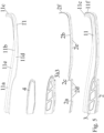
- the side wall 3a of the casing or wrapping element 3 can include a front wall section 3a1, if desired straight in the direction from one side to the other, as well as a wall section on the rear and on the back of the sides 3a2, if desired curved or with several mutually inclined sections, the wall section on the rear and on the back of the sides 3a2 defining together with the front wall section 3a1 the ring-shaped side wall 3a.
- front wall section 3a it can be shaped so as to define a first step 3a3 (see figure 5 ) directed, in use, downwards.
- the thickness or height of the side wall 3a decreases from the rear R towards the front F.
- the wall section on the rear and on the back of the sides 3a2 can be formed over a edge section 2a1 on the rear and on the back of the sides of the main plate element 2, so that once the casing or wrapping element 3 has been obtained above the latter, the external surface of the wall section on the rear and on the back of the sides 3a2 is flush or aligned with the external surface of the edge section 2a1 on the rear and on the back of the sides of the main plate element 2.
- the casing or wrapping element 3 further includes a base wall section 3b which extends from all or part of the lower edge of the side wall 3a towards the inside of the casing or wrapping element 3.
- the base wall section 3b extends towards the inside of the casing or wrapping element 3 only from the lower edge of the wall section on the rear and on the back of the sides 3a2.
- the base wall section 3b is annular so as to even define a central opening CO.
- This opening CO can have an extension (horizontal, in use, dimension) between about 60% and 95%, preferably between about 80% and 95% of the extension of the internal light or opening defined by the side wall 3a.
- the positioning zone PZ is defined laterally by the side wall 3a of the casing or wrapping element 3, and on the bottom of the base wall 3b and, if desired, by an intermediate part or central part of a rear portion 2a of the main plate 2.
- the positioning zone PZ could have any configuration, for example substantially like the rear of the main plate 2 with constant or even decreasing height moving away from the rear R.
- the main plate element 2 and the casing or wrapping element 3 are provided with mechanical means for mutual engagement or engagement with each other 5, 6.
- the main plate element 2 can delimit a plurality of openings 5 and/or protrusions, while the casing or wrapping element 3 has projecting portions 6 within the openings 5 and/or recesses for receiving the protrusions, so as to increase the mechanical constraint between the main plate element 2 and the casing or wrapping element 3.
- the mechanical engagement means 5, 6 are provided on the edge section 2a1 on the rear and on the back of the sides of the main plate element 2 and on the base wall 3b.
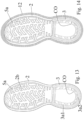
- openings 5, preferably non-passing can be provided on the edge section 2a1 on the rear and on the back of the sides of the main plate element 2. More specifically, several openings 5 can be provided spaced along the edge section 2a1 on the rear and on the back of the sides or perimetrically on the back and on the rear part of the sides.
- projecting portions 6 extend which each engage within a respective opening 5, so as to increase the mechanical constraint between the main plate element 2 and the casing or wrapping element 3.
- the openings 5, if provided, are open upwards and are closed at the bottom and formed at or immediately above a respective cleat 2d of the main base plate element 2.
- projecting portions 6 they could be formed or extend at or immediately below recesses formed in the base wall 3b.
- the openings 5 could have an irregular or regular configuration complementary to the projecting portions 6.
- the main plate element 2 may or may not include secondary non-passing openings 5a also in its front portion 2b, if desired also in this case vertically aligned or immediately above respective cleats 2e.
- the thickness of the main plate 2 could be any suitable, for example between 1 and 3 mm, preferably between 1.8 and 2.2 mm. Of course, the thickness of the main plate 2 depends on the tread design.
- the base or tread component 1 can include an edge portion projecting upwards from the main plate element 2 only at the rear, which edge portion is defined by the casing or wrapping element 3.
- the casing or wrapping element 3 is transparent or translucent so as to allow to see through it whole or part of the positioning zone PZ and thus one or more possible inserts 4 or solid or liquid material (even loose) housed in the same.
- the main plate element 2 has a front or anterior portion 2b and a rear portion 2a, if desired offset, in use, downwards with respect to the front portion 2b, between the front portion 2b and the rear portion 2a being defined or provided a second step 2c of connection or continuation of the main plate element 2.
- the front or anterior portion 2b is substantially flat or slightly curved and the same applies to the rear portion 2a.
- the casing or wrapping element 3 is made or obtained so as to be housed above the rear portion 2a.
- the casing or wrapping element 3 has a bulk, in plan, both in width and in length, corresponding to the rear portion 2a of the main plate 2, with the external lateral surface of the casing or wrapping element 3 or rather of the wall section of the wall section on the rear and on the back of the sides 3a2 substantially aligned with the lateral surface of the edge section 2a1 on the rear and on the back of the sides of the main plate element 2.
- the casing or wrapping element 3 has its own front, in use, wall section 3a1, in abutment or support, at the first step 3a3, against the second step 2c.
- the main plate element 2 can also have a tip 2f which extends upwards starting from the anterior or front edge 2b of the main body of the main plate element 2.
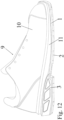
- Subject-matter of the present invention is also a footwear 9, for example a work or safety footwear, comprising an upper 10, a base or tread component 1 and a midsole 11 of connection between the upper 10 and the base or tread component 1, which midsole 11 is obtained by molding, preferably by injection, in a position between the upper 10 and the base or tread component 1.
- the sole of this footwear 9 is made of the base or tread component 1 and the midsole 11.
- the midsole 11 is made of polyurethane.
- the constraint between the upper 10 and the base or tread component 1 is guaranteed or obtained thanks to the production by molding, preferably by injection, of the midsole 11 directly on or around the upper 10 and the base or tread component 1.
- the footwear 9 can also include at least one shock-absorbing insert 4 or solid or liquid shock-absorbing or with rebounding capacity material housed in the positioning area PZ closed, if desired sealed, between the upper 10 and the base or tread component 1, thanks also to the midsole 11.
- the shock-absorbing insert 4 can be made of polymer, composite or other material, it can be solid or hollow, of regular or irregular shape, colored with neutral colors (white, black) or not.
- the insert could also be made up of a liquid inside a fluid-tight membrane or even directly poured into the positioning zone PZ.
- the insert 4 can have a configuration such that it is inserted substantially to measure or, if desired, even with a slight slack in the positioning zone PZ.
- the insert 4 once housed in the positioning zone PZ, does not protrude upwards or exceed the level of the casing or wrapping element 3.
- its top, in use, surface is substantially aligned with or lower than the top, in use, surface of the casing or wrapping element 3.
- the insert could also include solid or liquid material, even loose.
- the thickness or height of the insert 4 can or not decrease from the rear R towards the front F, in a manner corresponding to the side wall 3a.
- the midsole 11 can, for example, have an annular or tubular configuration.
- the midsole 11 has a rear section 11a which extends at and partly, in use, upwards, starting from the upper edge 3a4 of the casing or wrapping element 3 and a front section 11b which extends at and partly, in use, upwards, starting from the outer or perimeter edge 2g of the main plate element 2.
- the rear section 11a of the midsole extends at and partly, in use, upwards, starting from the upper edge 3a4 of the wall section on the rear and on the back of the sides 3a2, while the front section 11b extends at and partly, in use, upwards, starting from the outer or perimeter edge 2g of the front portion 2b of the main plate element 2.
- the rear section 11a of the midsole 11 can have a thickness smaller than the front section 11b.
- the midsole 11 can also include a tip 11c which rises upwards starting from the front end of the front portion 2b.
- the rear 11a and front 11b section then define a lower annular part 11d and an upper annular part 11e, the lower annular part 11d being constrained or made or molded around and on or within an upper section of the casing or wrapping element 3 and of the main plate element 2, while the upper annular part 11e is constrained or made or molded around and on or within a lower section of the upper 10.
- the upper 10 can comprise a body that is open or even closed at the bottom.
- footwear 9 or rather the respective upper 10 could also have a reinforced toe, for example by means of plastic or metal components.
- the footwear 9 could also include an insole or similar placed in the upper 10 or on the base or tread component 1.
- Subject-matter of the present invention is also a method for obtaining a base or tread component 1, comprising the following steps:
- the constraint between the main plate element 2 and the casing or wrapping element 3 is therefore ensured or obtained thanks to the realization by molding of the casing or wrapping element directly on the main plate element 2.
- a method for obtaining a footwear 9 includes the following steps:
- the constraint between the upper 10 and the base or tread component 2 is therefore guaranteed or obtained thanks to the realization by molding of the midsole 11 directly on these components, in such a way that a lower annular part 11d is obtained or molded around and on or within an upper section of the casing or wrapping element 3 and of the main plate element 2, while an upper annular part 11e of the midsole is made or molded around and on or within a lower section of the upper 10.
- the molding step of the midsole is preferably carried out by injection molding.
- This method can also include a step which involves arranging an insert 4 or solid or liquid material and, before obtaining the midsole 11, housing it in the positioning zone PZ defined by the casing or wrapping element 3.
- This housing step can naturally be carried out before or after the base or tread component 1 is placed in the mold 12.
- the insert 4 or the solid or liquid material will remain stably housed in the positioning zone between the base or tread component 2 and the upper 10.
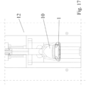
- the mold is opened, if desired by opening a ring component, part of the mold that contained the base or tread component is lowered and remains, on the last of the mold, the complete footwear (see figure 17 ).
- the idea behind the present invention is to obtain a system integrated into the sole or rather into the respective base or tread component 1, which can contain any insert with rebounding capacity.
- the base or tread component 1 is able to protect the insert 4 or the material, even loose, solid or liquid on all its sides, with a specific and anatomical design, and can keep the insert 4 still during the process of injecting or obtaining the midsole.
- the insert or the solid or liquid material can also be visible (if the base or tread component 1 is transparent or translucent), but it cannot be taken and ruined, and moreover there are no problems for the insert during the adhesion process of the component 1 with the midsole 11.
- subject-matter of this patent is a special sole or base component in TPU with a casing or "pocket” also made of TPU, but softer, which is preferably injected immediately after the tread and is welded to it generating a single body.
- the casing or wrapping element 3 or “pocket” has been designed and created with an upper perimeter edge which allows inserting and easily housing inside it a shock-absorbing insert 4 which can have the required dispersion features and which can be made of polymer or not, be solid or hollow, of regular or irregular shape, colored with neutral colors (white, black) or not.
- a casing or pocket 3 in fact, welded to the main plate 2 and specifically designed to protect and contain the insert with a "gasket” system that allows the insert to be blocked and prevent the passage of the material of the midsole during its formation is obtained.
- the midsole 11 is instead actually chemically "welded" to the base plate 2 and to the containment edge of the casing 3 and it covers the material of the insert for a few millimeters, without the possibility of penetrating into the positioning zone PZ, thanks to the containment edge which prevents the polyurethane of the midsole from entering between the insert 4 and the casing 3.
- the safety of the process is such that the casing or pocket 3 can also be transparent to show evidence of the result obtained.
- the present invention therefore represents a notable innovation compared to the state of the prior art, since it combines increased comfort with a system completely integrated into the footwear which eliminates the risk of breakage or malfunction.
Landscapes
- Engineering & Computer Science (AREA)
- Mechanical Engineering (AREA)
- Chemical & Material Sciences (AREA)
- Materials Engineering (AREA)
- Health & Medical Sciences (AREA)
- Epidemiology (AREA)
- General Health & Medical Sciences (AREA)
- Public Health (AREA)
- Footwear And Its Accessory, Manufacturing Method And Apparatuses (AREA)
Applications Claiming Priority (1)
| Application Number | Priority Date | Filing Date | Title |
|---|---|---|---|
| IT102022000024858A IT202200024858A1 (it) | 2022-12-01 | 2022-12-01 | Componente di base o battistrada per una calzatura come pure calzatura includente lo stesso componente. |
Publications (1)
| Publication Number | Publication Date |
|---|---|
| EP4378342A1 true EP4378342A1 (de) | 2024-06-05 |
Family
ID=85462348
Family Applications (1)
| Application Number | Title | Priority Date | Filing Date |
|---|---|---|---|
| EP23212738.1A Pending EP4378342A1 (de) | 2022-12-01 | 2023-11-28 | Basis oder laufteil für ein schuhwerk sowie schuhe, die dieselbe komponente enthalten |
Country Status (2)
| Country | Link |
|---|---|
| EP (1) | EP4378342A1 (de) |
| IT (1) | IT202200024858A1 (de) |
Citations (4)
| Publication number | Priority date | Publication date | Assignee | Title |
|---|---|---|---|---|
| WO2010007456A1 (en) * | 2008-07-14 | 2010-01-21 | Prince Sports, Inc. | An improved sole structure |
| US20150013185A1 (en) | 2013-07-11 | 2015-01-15 | Nike, Inc. | Sole structure for an article of footwear |
| IT201800010789A1 (it) * | 2018-12-04 | 2020-06-04 | Diadora Spa | Suola per calzature di sicurezza e metodo per la produzione di tale suola |
| EP3661383A1 (de) * | 2017-08-03 | 2020-06-10 | Base Protection Srl | Zur integration in schuhsohlen geeignete vorrichtung, die als polsterungs-, energieableitungs- und stabilisierungsmittel wirkt |
-
2022
- 2022-12-01 IT IT102022000024858A patent/IT202200024858A1/it unknown
-
2023
- 2023-11-28 EP EP23212738.1A patent/EP4378342A1/de active Pending
Patent Citations (4)
| Publication number | Priority date | Publication date | Assignee | Title |
|---|---|---|---|---|
| WO2010007456A1 (en) * | 2008-07-14 | 2010-01-21 | Prince Sports, Inc. | An improved sole structure |
| US20150013185A1 (en) | 2013-07-11 | 2015-01-15 | Nike, Inc. | Sole structure for an article of footwear |
| EP3661383A1 (de) * | 2017-08-03 | 2020-06-10 | Base Protection Srl | Zur integration in schuhsohlen geeignete vorrichtung, die als polsterungs-, energieableitungs- und stabilisierungsmittel wirkt |
| IT201800010789A1 (it) * | 2018-12-04 | 2020-06-04 | Diadora Spa | Suola per calzature di sicurezza e metodo per la produzione di tale suola |
Also Published As
| Publication number | Publication date |
|---|---|
| IT202200024858A1 (it) | 2024-06-01 |
Similar Documents
| Publication | Publication Date | Title |
|---|---|---|
| CN100441119C (zh) | 保护脚趾的凉鞋 | |
| US6871422B2 (en) | Protective, orthotic insert for footwear | |
| US6754981B1 (en) | Footwear structure with outsole bulges and midsole bladder | |
| US6412196B1 (en) | Contoured platform and footwear made therefrom | |
| CA2713114C (en) | Cushioned shoe construction | |
| US7350321B2 (en) | Shoe upper and methods of manufacture | |
| CA3042908C (en) | Metatarsal protector for safety footwear and associated manufacturing method | |
| JP7561124B2 (ja) | セーフティフットウェア用アウトソール、及びそのようなアウトソールの製造方法 | |
| GB2534873A (en) | Improvements in and relating to horseshoes | |
| US4404757A (en) | Heel filler and assembly for boots | |
| EP0572393B1 (de) | Fuss-schutzschale für sicherheitsschuh | |
| US20170231320A1 (en) | Fitting system and method for customizable footwear | |
| US6539647B2 (en) | Safety shoe | |
| CN106723664A (zh) | 楔、有楔的鞋底结构、模具和用于内模制物品的模制方法 | |
| US20050034332A1 (en) | Interchangeable shoe assembly | |
| EP2695537B1 (de) | Ohne klebeverfahren hergestellter leichtgewichtiger schuh | |
| EP4378342A1 (de) | Basis oder laufteil für ein schuhwerk sowie schuhe, die dieselbe komponente enthalten | |
| US4326345A (en) | Article of footwear | |
| EP4356773A1 (de) | Sohle für arbeitsschuhe | |
| US6874254B1 (en) | Thong-type shoe having a heel and a layered sole | |
| KR20080090758A (ko) | 아치 지지체가 형성된 신발 | |
| RU2793534C2 (ru) | Подошва для защитной обуви и способ изготовления такой подошвы | |
| KR200166176Y1 (ko) | 굽높이신발 | |
| GB2097649A (en) | Heel filler and shank stiffener/midsole assembly | |
| JP3084645U (ja) | 靴底構造 |
Legal Events
| Date | Code | Title | Description |
|---|---|---|---|
| PUAI | Public reference made under article 153(3) epc to a published international application that has entered the european phase |
Free format text: ORIGINAL CODE: 0009012 |
|
| STAA | Information on the status of an ep patent application or granted ep patent |
Free format text: STATUS: THE APPLICATION HAS BEEN PUBLISHED |
|
| AK | Designated contracting states |
Kind code of ref document: A1 Designated state(s): AL AT BE BG CH CY CZ DE DK EE ES FI FR GB GR HR HU IE IS IT LI LT LU LV MC ME MK MT NL NO PL PT RO RS SE SI SK SM TR |
|
| STAA | Information on the status of an ep patent application or granted ep patent |
Free format text: STATUS: REQUEST FOR EXAMINATION WAS MADE |
|
| 17P | Request for examination filed |
Effective date: 20241203 |
|
| RBV | Designated contracting states (corrected) |
Designated state(s): AL AT BE BG CH CY CZ DE DK EE ES FI FR GB GR HR HU IE IS IT LI LT LU LV MC ME MK MT NL NO PL PT RO RS SE SI SK SM TR |