EP4375966A1 - Verfahren und steuergerät zum betreiben eines motorrads in einer formation von motorrädern - Google Patents
Verfahren und steuergerät zum betreiben eines motorrads in einer formation von motorrädern Download PDFInfo
- Publication number
- EP4375966A1 EP4375966A1 EP23210698.9A EP23210698A EP4375966A1 EP 4375966 A1 EP4375966 A1 EP 4375966A1 EP 23210698 A EP23210698 A EP 23210698A EP 4375966 A1 EP4375966 A1 EP 4375966A1
- Authority
- EP
- European Patent Office
- Prior art keywords
- motorcycle
- formation
- hazard potential
- vehicles
- vehicle
- Prior art date
- Legal status (The legal status is an assumption and is not a legal conclusion. Google has not performed a legal analysis and makes no representation as to the accuracy of the status listed.)
- Granted
Links
Images


Classifications
-
- G—PHYSICS
- G08—SIGNALLING
- G08G—TRAFFIC CONTROL SYSTEMS
- G08G1/00—Traffic control systems for road vehicles
- G08G1/22—Platooning, i.e. convoy of communicating vehicles
-
- B—PERFORMING OPERATIONS; TRANSPORTING
- B60—VEHICLES IN GENERAL
- B60Q—ARRANGEMENT OF SIGNALLING OR LIGHTING DEVICES, THE MOUNTING OR SUPPORTING THEREOF OR CIRCUITS THEREFOR, FOR VEHICLES IN GENERAL
- B60Q1/00—Arrangement of optical signalling or lighting devices, the mounting or supporting thereof or circuits therefor
- B60Q1/26—Arrangement of optical signalling or lighting devices, the mounting or supporting thereof or circuits therefor the devices being primarily intended to indicate the vehicle, or parts thereof, or to give signals, to other traffic
- B60Q1/50—Arrangement of optical signalling or lighting devices, the mounting or supporting thereof or circuits therefor the devices being primarily intended to indicate the vehicle, or parts thereof, or to give signals, to other traffic for indicating other intentions or conditions, e.g. request for waiting or overtaking
- B60Q1/525—Arrangement of optical signalling or lighting devices, the mounting or supporting thereof or circuits therefor the devices being primarily intended to indicate the vehicle, or parts thereof, or to give signals, to other traffic for indicating other intentions or conditions, e.g. request for waiting or overtaking automatically indicating risk of collision between vehicles in traffic or with pedestrians, e.g. after risk assessment using the vehicle sensor data
- B60Q1/535—Arrangement of optical signalling or lighting devices, the mounting or supporting thereof or circuits therefor the devices being primarily intended to indicate the vehicle, or parts thereof, or to give signals, to other traffic for indicating other intentions or conditions, e.g. request for waiting or overtaking automatically indicating risk of collision between vehicles in traffic or with pedestrians, e.g. after risk assessment using the vehicle sensor data to prevent rear-end collisions, e.g. by indicating safety distance at the rear of the vehicle
-
- B—PERFORMING OPERATIONS; TRANSPORTING
- B60—VEHICLES IN GENERAL
- B60W—CONJOINT CONTROL OF VEHICLE SUB-UNITS OF DIFFERENT TYPE OR DIFFERENT FUNCTION; CONTROL SYSTEMS SPECIALLY ADAPTED FOR HYBRID VEHICLES; ROAD VEHICLE DRIVE CONTROL SYSTEMS FOR PURPOSES NOT RELATED TO THE CONTROL OF A PARTICULAR SUB-UNIT
- B60W30/00—Purposes of road vehicle drive control systems not related to the control of a particular sub-unit, e.g. of systems using conjoint control of vehicle sub-units
- B60W30/08—Active safety systems predicting or avoiding probable or impending collision or attempting to minimise its consequences
- B60W30/095—Predicting travel path or likelihood of collision
-
- B—PERFORMING OPERATIONS; TRANSPORTING
- B60—VEHICLES IN GENERAL
- B60W—CONJOINT CONTROL OF VEHICLE SUB-UNITS OF DIFFERENT TYPE OR DIFFERENT FUNCTION; CONTROL SYSTEMS SPECIALLY ADAPTED FOR HYBRID VEHICLES; ROAD VEHICLE DRIVE CONTROL SYSTEMS FOR PURPOSES NOT RELATED TO THE CONTROL OF A PARTICULAR SUB-UNIT
- B60W30/00—Purposes of road vehicle drive control systems not related to the control of a particular sub-unit, e.g. of systems using conjoint control of vehicle sub-units
- B60W30/08—Active safety systems predicting or avoiding probable or impending collision or attempting to minimise its consequences
- B60W30/095—Predicting travel path or likelihood of collision
- B60W30/0956—Predicting travel path or likelihood of collision the prediction being responsive to traffic or environmental parameters
-
- B—PERFORMING OPERATIONS; TRANSPORTING
- B60—VEHICLES IN GENERAL
- B60W—CONJOINT CONTROL OF VEHICLE SUB-UNITS OF DIFFERENT TYPE OR DIFFERENT FUNCTION; CONTROL SYSTEMS SPECIALLY ADAPTED FOR HYBRID VEHICLES; ROAD VEHICLE DRIVE CONTROL SYSTEMS FOR PURPOSES NOT RELATED TO THE CONTROL OF A PARTICULAR SUB-UNIT
- B60W50/00—Details of control systems for road vehicle drive control not related to the control of a particular sub-unit, e.g. process diagnostic or vehicle driver interfaces
- B60W50/08—Interaction between the driver and the control system
- B60W50/14—Means for informing the driver, warning the driver or prompting a driver intervention
-
- B—PERFORMING OPERATIONS; TRANSPORTING
- B60—VEHICLES IN GENERAL
- B60W—CONJOINT CONTROL OF VEHICLE SUB-UNITS OF DIFFERENT TYPE OR DIFFERENT FUNCTION; CONTROL SYSTEMS SPECIALLY ADAPTED FOR HYBRID VEHICLES; ROAD VEHICLE DRIVE CONTROL SYSTEMS FOR PURPOSES NOT RELATED TO THE CONTROL OF A PARTICULAR SUB-UNIT
- B60W50/00—Details of control systems for road vehicle drive control not related to the control of a particular sub-unit, e.g. process diagnostic or vehicle driver interfaces
- B60W50/08—Interaction between the driver and the control system
- B60W50/14—Means for informing the driver, warning the driver or prompting a driver intervention
- B60W2050/146—Display means
-
- B—PERFORMING OPERATIONS; TRANSPORTING
- B60—VEHICLES IN GENERAL
- B60W—CONJOINT CONTROL OF VEHICLE SUB-UNITS OF DIFFERENT TYPE OR DIFFERENT FUNCTION; CONTROL SYSTEMS SPECIALLY ADAPTED FOR HYBRID VEHICLES; ROAD VEHICLE DRIVE CONTROL SYSTEMS FOR PURPOSES NOT RELATED TO THE CONTROL OF A PARTICULAR SUB-UNIT
- B60W2300/00—Indexing codes relating to the type of vehicle
- B60W2300/36—Cycles; Motorcycles; Scooters
-
- B—PERFORMING OPERATIONS; TRANSPORTING
- B60—VEHICLES IN GENERAL
- B60W—CONJOINT CONTROL OF VEHICLE SUB-UNITS OF DIFFERENT TYPE OR DIFFERENT FUNCTION; CONTROL SYSTEMS SPECIALLY ADAPTED FOR HYBRID VEHICLES; ROAD VEHICLE DRIVE CONTROL SYSTEMS FOR PURPOSES NOT RELATED TO THE CONTROL OF A PARTICULAR SUB-UNIT
- B60W2554/00—Input parameters relating to objects
- B60W2554/40—Dynamic objects, e.g. animals, windblown objects
- B60W2554/402—Type
- B60W2554/4026—Cycles
-
- B—PERFORMING OPERATIONS; TRANSPORTING
- B60—VEHICLES IN GENERAL
- B60W—CONJOINT CONTROL OF VEHICLE SUB-UNITS OF DIFFERENT TYPE OR DIFFERENT FUNCTION; CONTROL SYSTEMS SPECIALLY ADAPTED FOR HYBRID VEHICLES; ROAD VEHICLE DRIVE CONTROL SYSTEMS FOR PURPOSES NOT RELATED TO THE CONTROL OF A PARTICULAR SUB-UNIT
- B60W2554/00—Input parameters relating to objects
- B60W2554/80—Spatial relation or speed relative to objects
-
- G—PHYSICS
- G08—SIGNALLING
- G08G—TRAFFIC CONTROL SYSTEMS
- G08G1/00—Traffic control systems for road vehicles
- G08G1/16—Anti-collision systems
- G08G1/161—Decentralised systems, e.g. inter-vehicle communication
- G08G1/163—Decentralised systems, e.g. inter-vehicle communication involving continuous checking
Definitions
- the invention relates to a method for operating a motorcycle in a formation of motorcycles, a corresponding control device and a corresponding computer program product.
- Motorcyclists can ride as a group in a formation.
- the motorcycles usually ride next to each other in two rows.
- the individual motorcyclist essentially orientates himself according to the motorcycle in front of him in the row and the motorcycle diagonally in front of him in the other row.
- the motorcycles can ride relatively close to each other without endangering each other.
- the positions of vehicles driving behind a motorcycle are automatically recorded and it is determined whether the recorded vehicles belong to a formation of the motorcycle. This information is used to determine the criticality of the respective vehicle for the motorcycle. For the same position, the criticality is determined to be greater for vehicles not belonging to the formation than for vehicles belonging to the formation, especially motorcycles.
- a motorcycle's collision warning system can, for example, tolerate shorter distances to members of its own formation than to other vehicles. This way, unnecessary collision warnings can be avoided when driving in formation. A motorcycle driver can thus concentrate better on driving in formation and driving safety within the formation can be increased.
- a method for operating a motorcycle in a formation of motorcycles wherein vehicles are detected in a rear space behind the motorcycle, a relative position of the vehicle to the motorcycle and a formation affiliation of the detected vehicle to the formation are determined for each detected vehicle, wherein a hazard potential of the vehicle for the motorcycle is determined using the relative position and the formation affiliation, wherein the hazard potential of vehicles belonging to the formation is determined to be lower than that of non-belonging vehicles with the same relative position.
- a formation of motorcycles can consist of at least two motorcycles.
- the motorcycles in the formation usually drive in the same lane.
- the motorcycles drive with a longitudinal and a lateral offset, or a longitudinal and lateral offset, to each other. This gives the formation its typical appearance as a zigzag line.
- Another formation which is particularly common in the USA, is two or sometimes three motorcycles side by side at the same height in one lane.
- a rear area can extend behind the motorcycle.
- the rear area can also extend to the right and left sides behind the motorcycle.
- Vehicles behind the motorcycle can be detected using a rear-facing sensor system of the motorcycle.
- a vehicle can be a car, truck, motorcycle or quad.
- the sensor system can have at least one sensor whose detection range at least partially covers the rear area.
- the sensor system can also include several sensors. The detection ranges of the sensors can overlap.
- the sensors can have the same or different detection principles. For example, a camera sensor, a radar sensor, a lidar sensor, an ultrasonic sensor or similar can be used as a sensor.
- a detected vehicle may or may not be a member of the formation.
- motorcycles may be members of the formation.
- Whether the vehicle is a member of the formation may be detected using a detection algorithm of the motorcycle.
- the detection algorithm may evaluate object features of the detected vehicles.
- the detection algorithm may output whether the vehicle is classified as belonging or foreign.
- the detection algorithm may calculate a probability of belonging to the formation. If the probability is above a threshold, the vehicle is detected as belonging to the formation. For example, the threshold may be 50%.
- a movement pattern of the vehicle can be evaluated to determine whether the vehicle belongs to the formation. If there are several vehicles, a relative arrangement of the vehicles to one another can be evaluated to determine which formation they belong to.
- the recognition algorithm can be executed on a control unit of the motorcycle.
- a hazard potential can represent a criticality for the motorcycle caused by another vehicle.
- the hazard potential can represent a probability of an impending collision between the other vehicle and the motorcycle.
- Potential consequences can also be of the collision, such as a probability of falling and/or a probability of injury.
- the risk potential for vehicles belonging to a formation can be determined differently than for other vehicles not belonging to it.
- the same value of the risk potential is reached for non-member vehicles at a much greater distance than for vehicles belonging to the formation.
- the vehicles belonging to the formation can therefore drive much closer to the motorcycle before they are assigned the same risk potential as an unmembered vehicle further away.
- a relative speed of the vehicles to the motorcycle can also be determined.
- the risk potential can also be determined using the relative speed.
- the relative speed can be used in addition to the relative position to determine the risk potential. For example, a vehicle driving close to the motorcycle can travel at a similar speed to the motorcycle. As a result, the vehicle has approximately no relative speed to the motorcycle. The close vehicle with the similar speed has a significantly lower risk potential for the motorcycle than a close vehicle that is also approaching the motorcycle at a relevant relative speed. Conversely, a vehicle driving close to the motorcycle at the moment and moving away from the motorcycle can have a lower risk potential than a vehicle slightly further away with an approximately constant distance to the motorcycle.
- An absolute speed of the motorcycle and/or the vehicles detected can also be used to determine the risk potential. It can be taken into account that at higher speeds, greater distances between vehicles are required.
- the hazard potential can be provided to a rider of the motorcycle via a human-machine interface of the motorcycle.
- the hazard potential can be provided separately for each vehicle in the rear area. This allows the rider to, for example, increase the distance to a vehicle with an increased hazard potential by accelerating, braking or swerves.
- the driver can also inform a driver of the other vehicle that he or she poses a threat, for example through gestures or another means of communication.
- the risk potential of the detected vehicle can be transmitted to the detected vehicle via a communication interface on the motorcycle.
- the risk potential can then be made available to a driver of the other vehicle. This driver can then recognize the risk posed by the motorcycle in front and react accordingly by reducing his speed and/or increasing the distance to the motorcycle in front.
- the other vehicle can also automatically react to the transmitted risk potential and, for example, increase the minimum distance used by an adaptive cruise control system.
- the hazard potential can be provided if the hazard potential is greater than a threshold value.
- a threshold value can be predefined. The threshold value can be selected so that the warning regarding the hazard potential is only provided if the hazard potential is relevant. If the hazard potential is smaller than the threshold value, the hazard potential does not need to be provided.
- the hazard potential can be provided if the hazard potential is greater than the threshold value for longer than a tolerance period. If the hazard potential is only briefly greater than the threshold value, the hazard potential can be omitted from being provided in order to prevent a rapid change from providing to not providing again.
- a minimum distance can be tolerated for a short time when entering a curve.
- the tolerance period can increase immunity to disturbances.
- the frequency of provision can be reduced.
- the method is preferably computer-implemented and can be implemented, for example, in software or hardware or in a hybrid form of software and hardware, for example in a driver assistance system.
- the approach presented here further creates a control device in the form of a driver assistance system for a vehicle, wherein the driver assistance system is designed to carry out, control or implement the steps of a variant of the method presented here in corresponding devices.
- the control unit or driver assistance system can be an electrical device with at least one computing unit for processing signals or data, at least one storage unit for storing signals or data, and at least one interface and/or a communication interface for reading in or outputting data that is embedded in a communication protocol.
- the computing unit can be, for example, a signal processor, a so-called system ASIC or a microcontroller for processing sensor signals and outputting data signals depending on the sensor signals.
- the storage unit can be, for example, a flash memory, an EPROM or a magnetic storage unit.
- the interface can be Sensor interface for reading the sensor signals from a sensor and/or as an actuator interface for outputting the data signals and/or control signals to an actuator.
- the communication interface can be designed to read or output the data wirelessly and/or via a cable.
- the interfaces can also be software modules that are present, for example, on a microcontroller alongside other software modules.
- a computer program product or computer program with program code that can be stored on a machine-readable carrier or storage medium such as a semiconductor memory, a hard disk memory or an optical memory and is used to carry out, implement and/or control the steps of the method according to one of the embodiments described above, in particular when the program product or program is executed on a computer or device.
- Figs. 1 to 3 show representations of traffic situations and a hazard potential determined using a method according to an embodiment.
- Fig.1 shows a representation of two different traffic situations with vehicles 102 driving behind a motorcycle 100.
- a car is driving behind the motorcycle 100 as vehicle 102.
- the car is driving too close to the motorcycle 100 and thus poses a danger to the motorcycle 100.
- several motorcycles are driving in a formation 104 behind the motorcycle 100 as vehicles 102.
- three motorcycles are driving in a staggered formation 104 behind the motorcycle 100.
- the formation 104 forms a zigzag line.
- the motorcycles belonging to the formation 104 drive close to the motorcycle 100 and each other.
- the motorcycles drive closer to the motorcycle 100 than the car.
- the motorcycles drive as a group and do not endanger each other due to the resulting small distances.
- the vehicles 102 driving in a rear area behind the motorcycle 100 are detected by a sensor system 106 of the motorcycle 100.
- a control unit 108 according to the approach presented here, information 110 from the sensor system 106 is evaluated and relative positions 112 of the vehicles 102 to the motorcycle 100 are determined.
- the formation affiliation 114 of the vehicles 102 is recognized in the control unit 108. Based on its relative position 112 and the formation affiliation 114, a hazard potential 116 is determined for each vehicle 102.
- a lower hazard potential 116 is determined for this vehicle 102 with the same relative position 112 than for a vehicle 102 not belonging to the formation 104. This also applies to vehicles 102 traveling laterally behind the motorcycle 100.
- a relative speed 118 of the vehicles 102 to the motorcycle 100 is also determined in the control unit 108.
- the relative speed 118 is also taken into account.
- a vehicle 102 belonging to the formation 104 for example, which approaches the motorcycle 100 from a relative position 112 with a relative speed 118, is assigned a greater hazard potential 116 than a vehicle 102 belonging to the formation 104 that is traveling at the same relative position 112 with an approximately constant distance from the motorcycle 100.
- a minimum distance 120 is determined for the respective vehicle 102 using the formation affiliation 114. If the vehicle 102 drives closer to the motorcycle 100 than its minimum distance 120, this vehicle 102 is assigned an increased risk potential 116. The minimum distance 120 is smaller for vehicles 102 belonging to the formation than for vehicles 102 not belonging to it.
- formation-associated vehicles 102 are identified when a group driving situation or formation driving is detected.
- Fig.2 shows a representation of two different traffic situations with vehicles 102 driving behind a motorcycle 100.
- the traffic situations essentially correspond to the traffic situations in Fig.1
- a danger zone 200 is shown here for each of the vehicles 102 in both traffic situations. The further the vehicle 102 penetrates into the respective danger zone 200, the greater the risk potential represented by the vehicle 102 for the motorcycle 100.
- the danger area 200 is significantly larger for vehicles 102 not belonging to formation 104 than for vehicles 102 or motorcycles belonging to formation 104.
- the danger potential is already recognized at a significantly greater distance from motorcycle 100.
- Fig.3 shows a representation of a group driving situation with determined hazard potentials 116 using a method according to an embodiment.
- the group driving situation essentially corresponds to the second traffic situation in Fig.1 and Fig.2 .
- All vehicles 102 are motorcycles and belong to the formation 104.
- a danger zone 200 is shown here for each motorcycle. The further the motorcycle penetrates into the danger zone 200, the greater its risk potential 116 is determined to be for the motorcycle driving ahead.
- the driver of the preceding motorcycle 100 is provided with the the danger potential 116 posed by the motorcycle following him is shown.
- the driver can thus react to the danger potential 116 present in the rear area and change the traffic situation through targeted intervention, such as braking, accelerating and/or swerving, so that the danger potential 116 is reduced.
- the driver can, for example, use hand signals and/or radio to request formation 104 to reduce the risk potential 116, i.e. to keep more distance and/or drive more slowly or less aggressively.
- the driver of the following motorcycle is shown the hazard potential 116 caused by him on a human-machine interface 300 of his motorcycle.
- the hazard potential 116 can be transmitted via a communication interface 302 between the motorcycles and displayed, for example, in a cockpit or head-up display of the following motorcycle.
- the hazard potential 116 is displayed on a signaling device 304 of the motorcycle 100 for following vehicles 102.
- the hazard potential 116 can be displayed using symbols, text and/or signal colors.
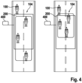
- Fig.4 shows a representation of two different group driving situations with different formation hazard potentials 400.
- four motorcycles are driving in formation 104.
- a hazard area 200 for the entire formation 104 is shown in the rear area behind the first motorcycle 100 of the formation 104.
- formation 104 is spread out and two of the motorcycles belonging to the formation are driving within the danger area 200, while one of the motorcycles is driving outside the danger area 200.
- the motorcycles of formation 104 driving behind motorcycle 100 represent a low formation danger potential 400.
- formation 104 is pulled together and three of the motorcycles belonging to the formation are driving within the danger zone 200.
- the motorcycles of formation 104 driving behind motorcycle 100 represent an increased formation danger potential 400.
- a formation speed and an average distance between the motorcycles belonging to the formation are taken into account.
- rear criticality is communicated to the driver and other systems.
- a method is presented to improve the driver's understanding of the safety of the driving formation and the world.
- the calculation of the hazard potential of the rear parts of the formation during a group driving scenario is presented.
- the system includes one or more rear-facing sensors to detect objects in the rear of the vehicle and to perform Criticality calculations.
- the system further includes a group ride detection module on or with the rear sensor and an on-board communication system, such as CAN.
- the system may also include other systems such as ABS, Motorcycle Stability Control (MSC), Traction Control Systems (TCS), Human Machine Interface (HMI), etc.
- the system may include a radio communication system and/or a warning display for other vehicles to inform them of the current threat they pose to the driver from behind.
- the approach presented here refers to a specific function for calculating the hazard potential of objects in rear traffic for the driver when driving in a group and providing this information to various interfaces so that the situation can be made safer and more comfortable for the driver and the surrounding traffic.
- Criticality means a probabilistic calculation of the risk to the driver's safety, such as the probability and consequences of a collision.
- This information can then be used to indicate to the driver that they should intervene or become aware of the increased risk. For example, they can drive slower.
- the driver could use the information to gesture to prompt others in the group to adjust their driving situation.
- the motorcycle could transmit the escalated situation to other vehicles via display or radio so that they can intervene.
- the risk potential for the driver is calculated based on information from one or more rear sensors, such as a radar or camera system.
- group driving objects are detected and marked. These objects are stored in the system memory as group driving objects. The system then makes predictions and calculations for different situations.
- an object riding in the rear of a group is detected as driving dangerously close to the ego vehicle if the object is detected in a prohibited zone for an extended period of time (if riding in a group).
- This zone may be different for objects not riding in the group, as objects riding in the group may be allowed to drive closer to the driver.
- Fig.1 the criticality calculation settings are adjusted as soon as the rear group driving situation and the objects are identified.
- TTC time to collision
- Fig.2 the criticality calculation settings are adjusted once the rear driving situation and objects are identified.
- the collision probability for all objects is predicted, but the thresholds are set differently in a group driving situation.
- the collective distances (e.g. longitudinal or transverse) of the group are less than the recommended collective group speed.
- the large rectangle with the color gradient on the road shows the possible criticality value based on the object distance
- the color bubbles on the side show the hazard potential of the current object ( Fig.3 ) or the formation ( Fig.4 ) at.
Landscapes
- Engineering & Computer Science (AREA)
- Mechanical Engineering (AREA)
- Automation & Control Theory (AREA)
- Transportation (AREA)
- Human Computer Interaction (AREA)
- Physics & Mathematics (AREA)
- General Physics & Mathematics (AREA)
- Traffic Control Systems (AREA)
Abstract
Description
- Die Erfindung betrifft ein Verfahren zum Betreiben eines Motorrads in einer Formation von Motorrädern, ein entsprechendes Steuergerät sowie ein entsprechendes Computerprogrammprodukt.
- Motorradfahrer können als Gruppe in einer Formation fahren. In der Formation fahren die Motorräder meist versetzt nebeneinander in zwei Reihen. Dabei orientiert sich der einzelne Motorradfahrer im Wesentlichen an dem vor ihm in der Reihe fahrenden Motorrad und an dem schräg vor ihm in der anderen Reihe fahrenden Motorrad. Innerhalb der Formation können die Motorräder mit relativ geringen Abständen zueinander fahren, ohne sich gegenseitig zu gefährden.
- Vor diesem Hintergrund werden mit dem hier vorgestellten Ansatz ein Verfahren zum Betreiben eines Motorrads in einer Formation von Motorrädern, ein entsprechendes Steuergerät, sowie ein entsprechendes Computerprogrammprodukt gemäß den unabhängigen Ansprüchen vorgestellt. Vorteilhafte Weiterbildungen und Verbesserungen des hier vorgestellten Ansatzes ergeben sich aus der Beschreibung und sind in den abhängigen Ansprüchen beschrieben.
- Bei dem hier vorgestellten Ansatz werden Positionen von hinter einem Motorrad fahrenden Fahrzeuge automatisiert erfasst und bestimmt, ob die erfassten Fahrzeuge einer Formation des Motorrads angehören. Mit diesen Informationen wird eine Kritikalität des jeweiligen Fahrzeugs für das Motorrad ermittelt. Dabei wird die Kritikalität bei gleicher Position für nicht zur Formation zugehörige Fahrzeuge größer ermittelt als für zur Formation gehörige Fahrzeuge, insbesondere Motorräder.
- Durch den hier vorgestellten Ansatz kann beispielsweise ein Kollisionswarnsystem des Motorrads kürzere Abstände zu Mitgliedern der eigenen Formation tolerieren als zu Fremdfahrzeugen. So können bei Formationsfahrt unnötige Kollisionswarnungen vermieden werden. Ein Fahrer des Motorrads kann sich so besser auf die Formationsfahrt konzentrieren und eine Fahrsicherheit innerhalb der Formation kann erhöht werden.
- Es wird ein Verfahren zum Betreiben eines Motorrads in einer Formation von Motorrädern vorgeschlagen, wobei Fahrzeuge in einem Rückraum hinter dem Motorrad erfasst werden, zu jedem erfassten Fahrzeug eine Relativposition des Fahrzeugs zum Motorrad und eine Formationszugehörigkeit des erfassten Fahrzeugs zu der Formation bestimmt wird, wobei ein Gefährdungspotenzial des Fahrzeugs für das Motorrad unter Verwendung der Relativposition und der Formationszugehörigkeit ermittelt wird, wobei das Gefährdungspotenzial von formationszugehörigen Fahrzeugen bei gleicher Relativposition geringer ermittelt wird, als von unzugehörigen Fahrzeugen.
- Ideen zu Ausführungsformen der vorliegenden Erfindung können unter anderem als auf den nachfolgend beschriebenen Gedanken und Erkenntnissen beruhend angesehen werden.
- Eine Formation von Motorrädern kann aus zumindest zwei Motorrädern bestehen. Die Motorräder der Formation fahren meist auf der gleichen Fahrspur. Dabei fahren die Motorräder mit einem Längsversatz und einem Seitenversatz beziehungsweise einem longitudinalen und lateralen Versatz zueinander. So ergibt sich das typische Erscheinungsbild der Formation als Zick-Zack-Linie.
- Eine andere Formation, welche besonders in den USA gefahren wird, sind zwei oder manchmal drei Motorräder nebeneinander auf gleicher Höhe in einer Spur.
- In manchen Fällen kann es auch vorkommen, dass die Motorräder in einer Reihe fahren.
- Ein Rückraum kann sich hinter dem Motorrad erstrecken. Der Rückraum kann sich auch rechts und links seitlich hinter dem Motorrad erstrecken. Fahrzeuge hinter dem Motorrad können unter Verwendung eines nach hinten gerichteten Sensorsystems des Motorrads erfasst werden. Ein Fahrzeug kann dabei ein PKW, LKW oder ein Motorrad oder Quad sein. Das Sensorsystem kann zumindest einen Sensor aufweisen, dessen Erfassungsbereich den Rückraum zumindest anteilig abdeckt. Das Sensorsystem kann auch mehrere Sensoren umfassen. Erfassungsbereiche der Sensoren können sich überlappen. Die Sensoren können gleiche oder unterschiedliche Erfassungsprinzipien aufweisen. Beispielsweise kann als Sensor ein Kamerasensor, ein Radarsensor, ein Lidarsensor, ein Ultraschallsensor oder ähnliches eingesetzt werden.
- Ein erfasstes Fahrzeug kann Mitglied der Formation sein oder nicht. Insbesondere können Motorräder Mitglieder der Formation sein. Ob das Fahrzeug Mitglied der Formation ist, kann unter Verwendung eines Erkennungsalgorithmus des Motorrads erkannt werden. Der Erkennungsalgorithmus kann Objektmerkmale der erkannten Fahrzeuge auswerten. Der Erkennungsalgorithmus kann ausgeben, ob das Fahrzeug als zugehörig oder fremd klassifiziert wird. Der Erkennungsalgorithmus kann eine Wahrscheinlichkeit der Formationszugehörigkeit berechnen. Wenn die Wahrscheinlichkeit über einem Schwellenwert liegt, wird das Fahrzeug als zugehörig zur Formation erkannt. Beispielsweise kann der Schwellenwert 50% sein.
- Beispielsweise kann ein Bewegungsmuster des Fahrzeugs ausgewertet werden, um zu erkennen, ob das Fahrzeug zur Formation gehört. Bei mehreren Fahrzeugen kann eine relative Anordnung der Fahrzeuge zueinander ausgewertet werden, um die Formationszugehörigkeit zu erkennen. Der Erkennungsalgorithmus kann auf einem Steuergerät des Motorrads ausgeführt werden.
- Ein Gefährdungspotenzial kann eine Kritikalität für das Motorrad durch ein anderes Fahrzeug abbilden. Beispielsweise kann das Gefährdungspotenzial eine Wahrscheinlichkeit für einen bevorstehenden Zusammenstoß des anderen Fahrzeugs mit dem eigenen Motorrad abbilden. Dabei können auch potenzielle Folgen des Zusammenstoßes, wie beispielsweise eine Sturzwahrscheinlichkeit und/oder Verletzungswahrscheinlichkeit betrachtet werden.
- Das Gefährdungspotenzial kann für formationszugehörige Fahrzeuge, insbesondere formationszugehörige Motorräder anders ermittelt werden als für unzugehörige andere Fahrzeuge. Dabei wird der gleiche Wert des Gefährdungspotenzials bei unzugehörigen Fahrzeugen bereits bei einem wesentlich größeren Abstand erreicht als bei formationszugehörigen Fahrzeugen. Die formationszugehörigen Fahrzeuge können also wesentlich näher an das Motorrad heranfahren, bevor ihnen das gleiche Gefährdungspotenzial zugewiesen wird, wie einem weiter entfernten unzugehörigen fremden Fahrzeug.
- Es kann ferner eine Relativgeschwindigkeit der Fahrzeuge zum Motorrad bestimmt werden. Das Gefährdungspotenzial kann ferner unter Verwendung der Relativgeschwindigkeit ermittelt werden. Die Relativgeschwindigkeit kann zusätzlich zur Relativposition verwendet werden, um das Gefährdungspotenzial zu ermitteln. Beispielsweise kann ein nahe am Motorrad fahrendes Fahrzeug mit einer ähnlichen Geschwindigkeit wie das Motorrad fahren. Dadurch weist das Fahrzeug näherungsweise keine Relativgeschwindigkeit zum Motorrad auf. Das nahe Fahrzeug mit der ähnlichen Geschwindigkeit weist für das Motorrad ein wesentlich geringeres Gefährdungspotenzial auf als ein nahes Fahrzeug, das sich auch noch mit einer relevanten Relativgeschwindigkeit an das Motorrad annähert. Umgekehrt kann ein momentan nahe am Motorrad fahrendes Fahrzeug, das sich von dem Motorrad entfernt ein geringeres Gefährdungspotenzial aufweisen als ein etwas weiter entferntes Fahrzeug mit näherungsweise gleichbleibendem Abstand zum Motorrad.
- Zum Ermitteln des Gefährdungspotenzials kann ferner eine Absolutgeschwindigkeit des Motorrads und/oder der erfassten Fahrzeuge verwendet werden. Dabei kann berücksichtigt werden, dass bei höheren Geschwindigkeiten größere Abstände zwischen den Fahrzeugen erforderlich sind.
- Das Gefährdungspotenzial kann über eine Mensch-Maschine-Schnittstelle des Motorrads für einen Fahrer des Motorrads bereitgestellt werden. Das Gefährdungspotenzial kann für jedes Fahrzeug im Rückraum separat bereitgestellt werden. Dadurch kann der Fahrer beispielsweise einen Abstand zu einem Fahrzeug mit erhöhtem Gefährdungspotenzial vergrößern, indem er beschleunigt, bremst oder ausweicht. Ebenso kann der Fahrer einem Fahrer des anderen Fahrzeugs beispielsweise durch Gesten oder über einen anderen Kommunikationsweg mitteilen, dass er eine Gefährdung darstellt.
- Das Gefährdungspotenzial des erfassten Fahrzeugs kann über eine Kommunikationsschnittstelle des Motorrads an das erfasste Fahrzeug übermittelt werden. Das Gefährdungspotenzial kann dann für einen Fahrer des anderen Fahrzeugs bereitgestellt werden. So kann dieser Fahrer die Gefährdung des vorausfahrenden Motorrads erkennen und darauf entsprechend reagieren, indem er seine Geschwindigkeit verringert und/oder einen Abstand zum vorausfahrenden Motorrad vergrößert. Ebenso kann das andere Fahrzeug automatisiert auf das übermittelte Gefährdungspotenzial reagieren und beispielsweise einen verwendeten Mindestabstand eines abstandsgeregelten Tempomats vergrößern.
- Das Gefährdungspotenzial kann über eine optische Signalisierungseinrichtung des Motorrads für andere Verkehrsteilnehmer bereitgestellt werden. Eine Signalisierungseinrichtung kann Leuchten und/oder Symbole aufweisen. Die Signalisierungseinrichtung kann beispielsweise ein Gefahrensymbol und/oder Text darstellen, um das Gefährdungspotenzial anzuzeigen. Dabei können in unterschiedlichen Situationen unterschiedliche Gefahrensymbole und/oder Texte angezeigt werden. Beispielsweise kann eine Aufforderung zum Halten von mehr Abstand dargestellt werden. Ebenso kann die Gefahr eines Auffahrunfalls dargestellt werden. Das Gefährdungspotenzial kann auch durch einen Farbton dargestellt werden.
- Das Gefährdungspotenzial kann bereitgestellt werden, wenn das Gefährdungspotenzial größer als ein Schwellenwert ist. Ein Schwellenwert kann vordefiniert sein. Der Schwellenwert kann so gewählt sein, dass die Warnung bezüglich des Gefährdungspotenzials nur bereitgestellt wird, wenn das Gefährdungspotenzial relevant ist. Wenn das Gefährdungspotenzial kleiner als der Schwellenwert ist, kann auf das Bereitstellen des Gefährdungspotenzials verzichtet werden.
- Das Gefährdungspotenzial kann bereitgestellt werden, wenn das Gefährdungspotenzial länger als eine Toleranzzeitdauer größer als der Schwellenwert ist. Wenn das Gefährdungspotenzial nur kurz größer als der Schwellenwert ist, kann auf das Bereitstellen des Gefährdungspotenzials verzichtet werden, um einen schnellen Wechsel von Bereitstellen und wieder nicht Bereitstellen zu verhindern.
- Ein Unterschreiten eines Mindestabstands kann so beispielsweise beim Einfahren in eine Kurve kurzzeitig toleriert werden. Durch die Toleranzzeitdauer kann eine erhöhte Störungsunempfindlichkeit erreicht werden. Zusätzlich kann eine Häufigkeit des Bereitstellens reduziert werden.
- Es kann ferner ein Formationsgefährdungspotenzial zumindest der im Rückraum befindlichen formationszugehörigen Fahrzeuge ermittelt werden. Ein Formationsgefährdungspotenzial kann das Gefährdungspotenzial von mehreren Fahrzeugen der Formation zusammenfassen und gemeinsam abbilden. Das Formationsgefährdungspotenzial kann basierend auf der Geschwindigkeit der gesamten Formation und der gemeinsamen Entfernung zwischen den Mitgliedern der Formation ermittelt werden. Das Formationsgefährdungspotenzial kann über die Mensch-Maschine-Schnittstelle, die Kommunikationsschnittstelle, und/oder die Signalisierungseinrichtung bereitgestellt werden. Das Formationsgefährdungspotenzial kann bereitgestellt werden, wenn sie größer als der Schwellenwert ist. Ebenso kann das Formationsgefährdungspotenzial bereitgestellt werden, wenn sie länger als die Toleranzzeitdauer größer als der Schwellenwert ist.
- Das Verfahren ist vorzugsweise computerimplementiert und kann beispielsweise in Software oder Hardware oder in einer Mischform aus Software und Hardware beispielsweise in einem Fahrerassistenzsystem implementiert sein.
- Der hier vorgestellte Ansatz schafft ferner ein Steuergerät in Form eines Fahrerassistenzsystems für ein Fahrzeug, wobei das Fahrerassistenzsystem dazu ausgebildet ist, um die Schritte einer Variante des hier vorgestellten Verfahrens in entsprechenden Einrichtungen durchzuführen, anzusteuern bzw. umzusetzen.
- Das Steuergerät bzw. Fahrerassistenzsystem kann ein elektrisches Gerät mit zumindest einer Recheneinheit zum Verarbeiten von Signalen oder Daten, zumindest einer Speichereinheit zum Speichern von Signalen oder Daten, und zumindest einer Schnittstelle und/oder einer Kommunikationsschnittstelle zum Einlesen oder Ausgeben von Daten, die in ein Kommunikationsprotokoll eingebettet sind, sein. Die Recheneinheit kann beispielsweise ein Signalprozessor, ein sogenannter System-ASIC oder ein Mikrocontroller zum Verarbeiten von Sensorsignalen und Ausgeben von Datensignalen in Abhängigkeit von den Sensorsignalen sein. Die Speichereinheit kann beispielsweise ein Flash-Speicher, ein EPROM oder eine magnetische Speichereinheit sein. Die Schnittstelle kann als Sensorschnittstelle zum Einlesen der Sensorsignale von einem Sensor und/oder als Aktorschnittstelle zum Ausgeben der Datensignale und/oder Steuersignale an einen Aktor ausgebildet sein. Die Kommunikationsschnittstelle kann dazu ausgebildet sein, die Daten drahtlos und/oder leitungsgebunden einzulesen oder auszugeben. Die Schnittstellen können auch Softwaremodule sein, die beispielsweise auf einem Mikrocontroller neben anderen Softwaremodulen vorhanden sind.
- Von Vorteil ist auch ein Computerprogrammprodukt oder Computerprogramm mit Programmcode, der auf einem maschinenlesbaren Träger oder Speichermedium wie einem Halbleiterspeicher, einem Festplattenspeicher oder einem optischen Speicher gespeichert sein kann und zur Durchführung, Umsetzung und/oder Ansteuerung der Schritte des Verfahrens nach einer der vorstehend beschriebenen Ausführungsformen verwendet wird, insbesondere wenn das Programmprodukt oder Programm auf einem Computer oder einer Vorrichtung ausgeführt wird.
- Es wird darauf hingewiesen, dass einige der möglichen Merkmale und Vorteile der Erfindung hierin mit Bezug auf unterschiedliche Ausführungsformen beschrieben sind. Ein Fachmann erkennt, dass die Merkmale des Steuergeräts und des Verfahrens in geeigneter Weise kombiniert, angepasst oder ausgetauscht werden können, um zu weiteren Ausführungsformen der Erfindung zu gelangen.
- Nachfolgend werden Ausführungsformen der Erfindung unter Bezugnahme auf die beigefügten Zeichnungen beschrieben, wobei weder die Zeichnungen noch die Beschreibung als die Erfindung einschränkend auszulegen sind.
-
Fign. 1 bis 3 zeigen Darstellungen von Verkehrssituationen und eines unter Verwendung eines Verfahrens gemäß einem Ausführungsbeispiel ermittelten Gefährdungspotenzials. - Die Figuren sind lediglich schematisch und nicht maßstabsgetreu. Gleiche Bezugszeichen bezeichnen gleiche oder gleichwirkende Merkmale.
-
Fig. 1 zeigt eine Darstellung von zwei unterschiedlichen Verkehrssituationen mit hinter einem Motorrad 100 fahrenden Fahrzeugen 102. In der ersten Verkehrssituation fährt als Fahrzeug 102 ein PKW hinter dem Motorrad 100. Der PKW fährt zu dicht auf das Motorrad 100 auf und stellt somit eine Gefahr für das Motorrad 100 dar. In der zweiten Verkehrssituation fahren als Fahrzeuge 102 mehrere Motorräder in einer Formation 104 hinter dem Motorrad 100. Beispielsweise fahren hier drei Motorräder in versetzt gestaffelter Formation 104 hinter dem Motorrad 100. Die Formation 104 bildet dabei eine Zick-Zack-Linie. Dabei fahren die zur Formation 104 formationszugehörigen Motorräder dicht auf das Motorrad 100 und aufeinander auf. Die Motorräder fahren dichter als der PKW auf das Motorrad 100 auf. Aufgrund der Formationszugehörigkeit der Motorräder fahren die Motorräder jedoch als Pulk und gefährden sich durch die resultierenden geringen Abstände nicht. - Bei dem hier vorgestellten Ansatz werden die in einem Rückraum hinter dem Motorrad 100 fahrenden Fahrzeuge 102 durch ein Sensorsystem 106 des Motorrads 100 erfasst. In einem Steuergerät 108 gemäß dem hier vorgestellten Ansatz werden Informationen 110 des Sensorsystems 106 ausgewertet und Relativpositionen 112 der Fahrzeuge 102 zum Motorrad 100 bestimmt. Ferner wird im Steuergerät 108 die Formationszugehörigkeit 114 der Fahrzeuge 102 erkannt. Basierend auf seiner Relativposition 112 und der Formationszugehörigkeit 114 wird für jedes Fahrzeug 102 ein Gefährdungspotenzial 116 ermittelt.
- Wenn ein Fahrzeug 102 zur Formation 104 gehört, wird für dieses Fahrzeug 102 bei gleicher Relativposition 112 ein geringeres Gefährdungspotenzial 116 ermittelt als für ein nicht zur Formation 104 gehörendes Fahrzeug 102. Dies gilt auch für seitlich versetzt hinter dem Motorrad 100 fahrende Fahrzeuge 102.
- In einem Ausführungsbeispiel wird im Steuergerät 108 ferner eine Relativgeschwindigkeit 118 der Fahrzeuge 102 zum Motorrad 100 bestimmt. Beim Ermitteln des Gefährdungspotenzials 116 wird dabei ferner die Relativgeschwindigkeit 118 berücksichtigt. Dadurch wird einem beispielsweise zur Formation 104 zugehörigen Fahrzeug 102, das sich von einer Relativposition 112 mit einer Relativgeschwindigkeit 118 an das Motorrad 100 annähert, ein größeres Gefährdungspotenzial 116 zugewiesen als einem zur Formation 104 zugehörigen Fahrzeug 102, das an der gleichen Relativposition 112 mit näherungsweise konstantem Abstand zum Motorrad 100 fährt.
- In einem Ausführungsbeispiel wird unter Verwendung der Formationszugehörigkeit 114 ein Mindestabstand 120 für das jeweilige Fahrzeug 102 bestimmt. Wenn das Fahrzeug 102 näher an das Motorrad 100 heranfährt als sein Mindestabstand 120, wird diesem Fahrzeug 102 ein erhöhtes Gefährdungspotenzial 116 zugewiesen. Der Mindestabstand 120 ist für formationszugehörige Fahrzeuge 102 kleiner als für unzugehörige Fahrzeuge 102.
- In einem Ausführungsbeispiel werden formationszugehörige Fahrzeuge 102 identifiziert, wenn eine Gruppenfahrsituation beziehungsweise eine Formationsfahrt erkannt wird.
-
Fig. 2 zeigt eine Darstellung von zwei unterschiedlichen Verkehrssituationen mit hinter einem Motorrad 100 fahrenden Fahrzeugen 102. Die Verkehrssituationen entsprechen dabei im Wesentlichen den Verkehrssituationen inFig. 1 . Zusätzlich dazu ist hier für die Fahrzeuge 102 in beiden Verkehrssituationen je ein Gefährdungsbereich 200 dargestellt. Je weiter das Fahrzeug 102 in den jeweiligen Gefährdungsbereich 200 eindringt, umso größer ist das durch das Fahrzeug 102 dargestellte Gefährdungspotenzial für das Motorrad 100. - Der Gefährdungsbereich 200 ist für zur Formation 104 unzugehörige Fahrzeuge 102 wesentlich größer als für zur Formation 104 formationszugehörige Fahrzeuge 102 beziehungsweise Motorräder. So wird für unzugehörige Fahrzeuge 102 bei einem wesentlich größeren Abstand zum Motorrad 100 bereits das Gefährdungspotenzial erkannt.
-
Fig. 3 zeigt eine Darstellung einer Gruppenfahrsituation mit ermittelten Gefährdungspotenzialen 116 unter Verwendung eines Verfahrens gemäß einem Ausführungsbeispiel. Die Gruppenfahrsituation entspricht dabei im Wesentlichen der zweiten Verkehrssituation inFig. 1 undFig. 2 . Alle Fahrzeuge 102 sind Motorräder und sind zu der Formation 104 zugehörig. Zusätzlich ist hier für jedes Motorrad ein Gefährdungsbereich 200 dargestellt. Je weiter das Motorrad in den Gefährdungsbereich 200 eindringt, umso größer wird sein Gefährdungspotenzial 116 für das jeweils vorausfahrende Motorrad ermittelt. - In einem Ausführungsbeispiel wird dem Fahrer des vorausfahrenden Motorrads 100 über eine Mensch-Maschine-Schnittstelle 300 des Motorrads 100 das von dem ihm folgenden Motorrad ausgehende Gefährdungspotenzial 116 dargestellt. So kann der Fahrer auf das im Rückraum bestehende Gefährdungspotenzial 116 reagieren und die Verkehrssituation durch einen gezielten Eingriff, wie beispielsweise Bremsen, Beschleunigen und/oder Ausweichen so verändern, dass das Gefährdungspotenzial 116 verringert wird.
- Alternativ oder ergänzend kann der Fahrer beispielsweise durch Handzeichen und/oder Sprechfunk die Formation 104 auffordern, das Gefährdungspotenzial 116 zu verringern, also mehr Abstand zu halten und/oder langsamer beziehungsweise weniger aggressiv zu fahren.
- In einem Ausführungsbeispiel wird dem Fahrer des folgenden Motorrads das durch ihn verursachte Gefährdungspotenzial 116 auf einer Mensch-Maschine-Schnittstelle 300 seines Motorrads angezeigt. Beispielsweise kann das Gefährdungspotenzial 116 über eine Kommunikationsschnittstelle 302 zwischen den Motorrädern übermittelt werden und beispielsweise in einem Cockpit oder Headup-Display des folgenden Motorrads angezeigt werden.
- In einem Ausführungsbeispiel wird das Gefährdungspotenzial 116 auf einer Signalisierungseinrichtung 304 des Motorrads 100 für nachfolgende Fahrzeuge 102 angezeigt. Beispielsweise kann das Gefährdungspotenzial 116 durch Symbole, Text und/oder Signalfarben angezeigt werden. Dabei können insbesondere immer auffälligere Symbole, Textdarstellungen und/oder Signalfarben verwendet werden, je größer das angezeigte Gefährdungspotenzial 116 ist.
-
Fig. 4 zeigt eine Darstellung von zwei unterschiedlichen Gruppenfahrsituationen mit unterschiedlichen Formationsgefährdungspotenzialen 400. In beiden Gruppenfahrsituationen fahren vier Motorräder in Formation 104. In beiden Gruppenfahrsituationen ist ein Gefährdungsbereich 200 für die ganze Formation 104 im Rückraum hinter dem ersten Motorrad 100 der Formation 104 dargestellt. - In der ersten Gruppenfahrsituation ist die Formation 104 auseinandergezogen und zwei der formationszugehörigen Motorräder fahren innerhalb des Gefährdungsbereichs 200, während eines der Motorräder außerhalb des Gefährdungsbereichs 200 fährt. Dabei stellen die hinter dem Motorrad 100 fahrenden Motorräder der Formation 104 ein niedriges Formationsgefährdungspotenzial 400 dar.
- In der zweiten Gruppenfahrsituation ist die Formation 104 zusammengezogen und drei der formationszugehörigen Motorräder fahren innerhalb des Gefährdungsbereichs 200. Dabei stellen die hinter dem Motorrad 100 fahrenden Motorräder der Formation 104 ein erhöhtes Formationsgefährdungspotenzial 400 dar.
- Um das Formationsgefährdungspotenzial 400 zu ermitteln, werden insbesondere eine Formationsgeschwindigkeit und eine mittlere Distanz zwischen den formationszugehörigen Motorrädern berücksichtigt.
- Nachfolgend werden mögliche Ausgestaltungen der Erfindung nochmals zusammengefasst bzw. mit einer geringfügig anderen Wortwahl dargestellt.
- Es wird die Bestimmung von Informationen zur hinteren Kritikalität bei der Gruppenfahrt vorgestellt.
- Es wird eine Berechnung und Anzeige von Informationen über die hintere Kritikalität (Sicherheit) für den Fahrer vorgeschlagen, während dieser in einer Gruppe fährt. Es wird auch vorgeschlagen, die Informationen über die hintere Kritikalität an andere Motorradsysteme zur Funktionsanpassung und/oder andere Fahrzeuge weiterzugeben.
- Während des Gruppenfahrmodus wird die hintere Kritikalität von Objekten in einem Pulk von Gruppenfahrern berechnet. In einer Ausführungsform wird die hintere Kritikalität bzw. Heckkritikalität von anderen Verkehrsobjekten berechnet. In einer Ausführungsform wird das Gefährdungspotenzial des gesamten Verbandes, insbesondere der Teile des Verbandes hinter dem Fahrer, berechnet.
- In einer Ausführungsform wird die hintere Kritikalität an den Fahrer und andere Systeme weitergegeben.
- Es wird eine Methode zur Verbesserung des Verständnisses des Fahrers für die Sicherheit der Fahrformation und der Welt vorgestellt. Insbesondere wird die Berechnung des Gefährdungspotenzials der hinteren Teile der Formation während eines Gruppenfahrszenarios vorgestellt.
- Das System umfasst einen oder mehrere nach hinten gerichtete Sensoren zur Erkennung von Objekten im hinteren Fahrzeugbereich und zur Durchführung von Kritikalitätsberechnungen. Das System umfasst ferner ein Modul zur Erkennung von Gruppenfahrten am oder mit dem hinteren Sensor und ein bordeigenes Kommunikationssystem, wie z. B. CAN. Das System kann auch andere Systeme wie ABS, Motorradstabilitätsregler (MSC), Traktionskontrollsysteme (TCS), Mensch-Maschine-Schnittstelle (HMI) usw. umfassen. Darüber hinaus kann das System ein Funkkommunikationssystem und/oder eine Warnanzeige für andere Fahrzeuge umfassen, um diese über die aktuelle Gefährdung zu informieren, die sie von hinten für den Fahrer darstellen.
- Beim Fahren in einer Gruppenformation ist die Verkehrssituation zwischen normalen Vierrad (4W) und Zweirad (2W) Verkehrssicherheitsszenarien sehr unterschiedlich. Objekte, die Teil der Formation sind und solche, die es nicht sind, haben unterschiedliche Auswirkungen auf die Sicherheit des Fahrers. Objekte können sich in diesen Situationen anders verhalten, als es ein herkömmliches Fahrerassistenzsystem (Advanced Rider Assistance System, ARAS) erwarten würde.
- Der hier vorgestellte Ansatz bezieht sich auf eine spezifische Funktion zur Berechnung des Gefährdungspotenzials von Objekten im rückwärtigen Verkehr für den Fahrer, wenn er in einer Gruppe fährt, und zur Bereitstellung dieser Informationen an verschiedene Schnittstellen, so dass die Situation für den Fahrer und den umgebenden Verkehr sicherer und komfortabler gestaltet werden kann. Kritikalität bedeutet hier eine probabilistische Berechnung des Risikos für die Sicherheit des Fahrers, wie z. B. die Wahrscheinlichkeit und die Folgen eines Zusammenstoßes.
- Diese Informationen können dann verwendet werden, um dem Fahrer anzuzeigen, dass er eingreifen oder sich der erhöhten Gefährdung bewusstwerden soll. Zum Beispiel kann er langsamer fahren.
- Oder der Fahrer könnte die Informationen nutzen, um andere in der Gruppe mit Gesten zu veranlassen, ihre Fahrsituation anzupassen.
- Oder das Motorrad könnte die eskalierte Situation per Display oder über Funk an andere Fahrzeuge weitergeben, damit diese eingreifen können.
- Das Gefährdungspotenzial für den Fahrer wird basierend auf der Information von einem oder mehreren hinteren Sensoren, wie z. B. ein Radar- oder Kamerasystem, berechnet.
- Zunächst wird eine Gruppenfahrsituation erkannt. Dann werden Gruppenfahrobjekte erkannt und markiert. Diese Objekte werden im Systemspeicher als Gruppenfahrobjekte gespeichert. Das System erstellt dann Vorhersagen und Berechnungen für verschiedene Situationen.
- Zum Beispiel wird erkannt, dass ein Objekt, welches hinten in einer Gruppe mitfährt, gefährlich nahe an das Ego-Fahrzeug heranfährt, wenn das Objekt über einen längeren Zeitraum in einer nicht erlaubten Zone erfasst wird (wenn es in einer Gruppe mitfährt). Diese Zone kann für nicht in der Gruppe fahrende Objekte unterschiedlich sein, da in der Gruppe fahrenden Objekten erlaubt werden kann, näher am Fahrer zu fahren.
- In
Fig. 1 werden die Einstellungen der Kritikalitätsberechnung angepasst, sobald die hintere Gruppenfahrsituation und die Objekte identifiziert sind. - Wenn sich ein hinteres, in einer Gruppe fahrendes Objekt dem Fahrer auf unsichere Weise nähert und/oder eine mögliche Kollision vorausgesagt wird, hat das Objekt eine Zeit bis zur Kollision (TTC), die unter einem zulässigen Schwellenwert liegt. Diese Einstellung kann für nicht in der Gruppe fahrende Objekte unterschiedlich sein.
- In
Fig. 2 werden die Einstellungen der Kritikalitätsberechnung angepasst, sobald die hintere Fahrsituation und die Objekte identifiziert sind. Die Kollisionswahrscheinlichkeit für alle Objekte wird vorhergesagt, aber die Schwellenwerte werden in einer Gruppenfahrsituation anders festgelegt. - Wenn der Abstand zwischen den in der Gruppe fahrenden Objekten gefährlich gering ist und/oder andere in der Gruppe fahrende Objekte sich einander auf gefährliche Weise nähern, sind die kollektiven Abstände (z. B. in Längs- oder Querrichtung) der Gruppe geringer als für die kollektive Gruppengeschwindigkeit empfohlen.
- Wenn diese Kritikalitätsinformationen empfangen werden, können sie für den Fahrer visualisiert werden.
- In den
Fign. 3 und4 zeigt das große Rechteck mit dem Farbverlauf auf der Straße den möglichen Kritikalitätswert auf der Grundlage der Objektentfernung an, und die Farbblasen an der Seite zeigen das Gefährdungspotenzial des aktuellen Objekts (Fig. 3 ) oder der Formation (Fig. 4 ) an. - Abschließend ist darauf hinzuweisen, dass Begriffe wie "aufweisend", "umfassend", etc. keine anderen Elemente oder Schritte ausschließen und Begriffe wie "eine" oder "ein" keine Vielzahl ausschließen. Bezugszeichen in den Ansprüchen sind nicht als Einschränkung anzusehen.
Claims (11)
- Verfahren zum Betreiben eines Motorrads (100) in einer Formation (104) von Motorrädern, wobei Fahrzeuge (102) in einem Rückraum hinter dem Motorrad (100) erfasst werden, zu jedem erfassten Fahrzeug (102) eine Relativposition (112) des Fahrzeugs (102) zum Motorrad (100) und eine Formationszugehörigkeit (114) des erfassten Fahrzeugs (102) zu der Formation (104) bestimmt wird, wobei ein Gefährdungspotenzial (116) des Fahrzeugs (102) für das Motorrad (100) unter Verwendung der Relativposition (112) und der Formationszugehörigkeit (114) ermittelt wird, wobei das Gefährdungspotenzial (116) von formationszugehörigen Fahrzeugen (102) bei gleicher Relativposition (112) geringer ermittelt wird, als von unzugehörigen Fahrzeugen (102).
- Verfahren gemäß Anspruch 1, bei dem ferner eine Relativgeschwindigkeit (118) der Fahrzeuge (102) zum Motorrad (100) bestimmt wird, wobei das Gefährdungspotenzial (116) ferner unter Verwendung der Relativgeschwindigkeit (118) ermittelt wird.
- Verfahren gemäß einem der vorhergehenden Ansprüche, bei dem das Gefährdungspotenzial (116) über eine Mensch-Maschine-Schnittstelle (300) des Motorrads (100) für einen Fahrer des Motorrads (100) bereitgestellt wird.
- Verfahren gemäß einem der vorhergehenden Ansprüche, bei dem das Gefährdungspotenzial (116) des erfassten Fahrzeugs (102) über eine Kommunikationsschnittstelle (302) des Motorrads (100) an das erfasste Fahrzeug (102) übermittelt wird.
- Verfahren gemäß einem der vorhergehenden Ansprüche, bei dem das Gefährdungspotenzial (116) über eine optische Signalisierungseinrichtung (304) des Motorrads (100) für andere Verkehrsteilnehmer bereitgestellt wird.
- Verfahren gemäß einem der Ansprüche 3 bis 5, bei dem das Gefährdungspotenzial (116) bereitgestellt wird, wenn das Gefährdungspotenzial (116) größer als ein Schwellenwert ist.
- Verfahren gemäß Anspruch 6, bei dem das Gefährdungspotenzial (116) bereitgestellt wird, wenn das Gefährdungspotenzial (116) länger als eine Toleranzzeitdauer größer als der Schwellenwert ist.
- Verfahren gemäß einem der vorhergehenden Ansprüche, bei dem ferner ein Formationsgefährdungspotenzial (400) zumindest der im Rückraum befindlichen formationszugehörigen Fahrzeuge (102) ermittelt wird.
- Steuergerät (108), wobei das Steuergerät (108) dazu konfiguriert ist, das Verfahren gemäß einem der vorhergehenden Ansprüche in entsprechenden Einrichtungen auszuführen, umzusetzen und/oder anzusteuern.
- Computerprogrammprodukt, das dazu eingerichtet ist, einen Prozessor bei Ausführung des Computerprogrammprodukts dazu anzuleiten, das Verfahren gemäß einem der Ansprüche 1 bis 8 auszuführen, umzusetzen und/oder anzusteuern.
- Maschinenlesbares Speichermedium, auf dem das Computerprogrammprodukt gemäß Anspruch 10 gespeichert ist.
Applications Claiming Priority (1)
| Application Number | Priority Date | Filing Date | Title |
|---|---|---|---|
| DE102022212482.0A DE102022212482A1 (de) | 2022-11-23 | 2022-11-23 | Verfahren und Steuergerät zum Betreiben eines Motorrads in einer Formation von Motorrädern |
Publications (2)
| Publication Number | Publication Date |
|---|---|
| EP4375966A1 true EP4375966A1 (de) | 2024-05-29 |
| EP4375966B1 EP4375966B1 (de) | 2025-11-05 |
Family
ID=88838909
Family Applications (1)
| Application Number | Title | Priority Date | Filing Date |
|---|---|---|---|
| EP23210698.9A Active EP4375966B1 (de) | 2022-11-23 | 2023-11-17 | Verfahren und steuergerät zum betreiben eines motorrads in einer formation von motorrädern |
Country Status (2)
| Country | Link |
|---|---|
| EP (1) | EP4375966B1 (de) |
| DE (1) | DE102022212482A1 (de) |
Citations (3)
| Publication number | Priority date | Publication date | Assignee | Title |
|---|---|---|---|---|
| JP2019185799A (ja) * | 2019-07-02 | 2019-10-24 | スズキ株式会社 | 車両間情報共有システム |
| DE102019203543A1 (de) * | 2019-03-15 | 2020-09-17 | Audi Ag | Verfahren, Computerprogrammprodukt und Kraftfahrzeug zur Ermittlung eines Unfallrisikos |
| DE102020202986A1 (de) * | 2020-03-10 | 2021-09-16 | Robert Bosch Gesellschaft mit beschränkter Haftung | Verfahren und Vorrichtung zum Betreiben eines Motorrads |
Family Cites Families (6)
| Publication number | Priority date | Publication date | Assignee | Title |
|---|---|---|---|---|
| DE102011009483A1 (de) * | 2011-01-26 | 2012-07-26 | Audi Ag | Verfahren zum Betrieb eines längsführenden Fahrerassistenzsystems eines Kraftfahrzeugs und Kraftfahrzeug |
| US9632507B1 (en) * | 2016-01-29 | 2017-04-25 | Meritor Wabco Vehicle Control Systems | System and method for adjusting vehicle platoon distances based on predicted external perturbations |
| JP2020035348A (ja) * | 2018-08-31 | 2020-03-05 | いすゞ自動車株式会社 | 車両用情報提供装置および車両 |
| DE102019205881A1 (de) * | 2019-04-25 | 2020-10-29 | Robert Bosch Gmbh | Verfahren und Vorrichtung zur automatischen Einstellung eines Geschwindigkeits- oder Abstandsregelungssystems eines einspurigen Kraftfahrzeugs |
| DE102019211592A1 (de) * | 2019-08-01 | 2021-02-04 | Robert Bosch Gmbh | Verfahren zum Betreiben eines Fahrzeugs in einem Fahrzeugverbund |
| DE102019214121A1 (de) * | 2019-09-17 | 2021-03-18 | Continental Automotive Gmbh | Verfahren zum Betrieb eines Fahrerassistenzsystems |
-
2022
- 2022-11-23 DE DE102022212482.0A patent/DE102022212482A1/de active Pending
-
2023
- 2023-11-17 EP EP23210698.9A patent/EP4375966B1/de active Active
Patent Citations (3)
| Publication number | Priority date | Publication date | Assignee | Title |
|---|---|---|---|---|
| DE102019203543A1 (de) * | 2019-03-15 | 2020-09-17 | Audi Ag | Verfahren, Computerprogrammprodukt und Kraftfahrzeug zur Ermittlung eines Unfallrisikos |
| JP2019185799A (ja) * | 2019-07-02 | 2019-10-24 | スズキ株式会社 | 車両間情報共有システム |
| DE102020202986A1 (de) * | 2020-03-10 | 2021-09-16 | Robert Bosch Gesellschaft mit beschränkter Haftung | Verfahren und Vorrichtung zum Betreiben eines Motorrads |
Also Published As
| Publication number | Publication date |
|---|---|
| EP4375966B1 (de) | 2025-11-05 |
| DE102022212482A1 (de) | 2024-05-23 |
Similar Documents
| Publication | Publication Date | Title |
|---|---|---|
| DE112019003322B4 (de) | Fahrzeugsteuervorrichtung | |
| DE102016116911B4 (de) | Vorrichtung und Verfahren zum Steuern des automatischen Fahrens eines Fahrzeugs | |
| EP1977946B1 (de) | Fahrerassistenzsystems für die Umfeld-Erkennung und Erfassung einer Solltrajektorie | |
| DE112018006009B4 (de) | Bremsunterstützungsvorrichtung, steuerungsvorrichtung und bremsunterstützungsverfahren für ein fahrzeug | |
| DE102018203121B4 (de) | Verfahren zur Berechnung einer AR-Einblendung von Zusatzinformationen für eine Anzeige auf einer Anzeigeeinheit, Vorrichtung zur Durchführung des Verfahrens sowie Kraftfahrzeug und Computerprogramm | |
| EP1486933B1 (de) | Fahrerassistenzsystem | |
| DE102009007885B4 (de) | Verfahren zur Erkennung von auf die eigene Fahrspur einscherenden oder aus der eigenen Fahrspur ausscherenden Fahrzeugen | |
| DE102012216112A1 (de) | Verfahren und Informationssystem zur Ermittlung eines vom Fahrer beabsichtigen oder nicht beabsichtigten Fahrspurwechsels bei einer Fahrt eines Fahrzeugs | |
| DE102013210941A1 (de) | Verfahren und Vorrichtung zum Betreiben eines Fahrzeugs | |
| EP4117987B1 (de) | Verfahren und vorrichtung zum betreiben eines motorrads | |
| EP3280624A1 (de) | Steuerungs-system und verfahren zum ermöglichen eines einscherens eines anderen kraftfahrzeugs aus einer nachbarspur im acc-betrieb des eigenen kraftfahrzeugs | |
| DE112021003707T5 (de) | Steuervorrichtung, steuerverfahren und programm | |
| EP3281830A1 (de) | Steuerungssystem und steuerungsverfahren zum bestimmen einer trajektorie und zum erzeugen von zugehörigen signalen oder steuerbefehlen | |
| EP3281831A1 (de) | Steuerungssystem und steuerungsverfahren zum ermitteln einer wahrscheinlichkeit für einen fahrspurwechsel eines vorausfahrenden kraftfahrzeugs | |
| DE102014108616A1 (de) | Fahrtassistenzsteuerungseinrichtung für ein Fahrzeug | |
| EP3847067B1 (de) | Verfahren und vorrichtung zum absichern eines überholvorgangs eines auf ein fahrrad auffahrenden fahrzeugs | |
| DE102014215274B4 (de) | Verfahren und Vorrichtung zum Betreiben eines Fahrzeugs | |
| DE102008020007A1 (de) | Verfahren zum Unterstützen eines Fahrers beim Fahren mit einem Fahrzeug mit einer Fahrspurerkennung | |
| DE102016216738A1 (de) | Verfahren und Vorrichtung zum Steuern eines Fahrzeugs | |
| DE102012214829A1 (de) | Verfahren und Vorrichtung zum Darstellen einer Ausweichtrajektorie zur Kollisionsvermeidung für ein Fahrzeug | |
| DE102018215509A1 (de) | Verfahren und Vorrichtung zum Betrieb eines zumindest teilweise automatisiert betriebenen ersten Fahrzeugs | |
| DE102021200467A1 (de) | Computerimplementiertes Verfahren, Steuergerät und Computerprogramm zum Regeln und/oder Steuern einer Fahrfunktion eines automatisiert betreibbaren Fahrzeuges und zum Aufbauen einer Warnkaskade für ein Auslösen der Fahrfunktion und automatisches Notbremsungs- und/oder Notlenkungsmodul für ein automatisiert betreibbares Fahrzeug umfassend ein derartiges Steuergerät | |
| DE102022202714A1 (de) | Assistenzsystem sowie Verfahren zum Steuern eines | |
| DE102016203968A1 (de) | Identifikation eines Fahrers eines Kraftfahrzeugs | |
| EP4375966B1 (de) | Verfahren und steuergerät zum betreiben eines motorrads in einer formation von motorrädern |
Legal Events
| Date | Code | Title | Description |
|---|---|---|---|
| PUAI | Public reference made under article 153(3) epc to a published international application that has entered the european phase |
Free format text: ORIGINAL CODE: 0009012 |
|
| STAA | Information on the status of an ep patent application or granted ep patent |
Free format text: STATUS: THE APPLICATION HAS BEEN PUBLISHED |
|
| AK | Designated contracting states |
Kind code of ref document: A1 Designated state(s): AL AT BE BG CH CY CZ DE DK EE ES FI FR GB GR HR HU IE IS IT LI LT LU LV MC ME MK MT NL NO PL PT RO RS SE SI SK SM TR |
|
| STAA | Information on the status of an ep patent application or granted ep patent |
Free format text: STATUS: REQUEST FOR EXAMINATION WAS MADE |
|
| 17P | Request for examination filed |
Effective date: 20241129 |
|
| RBV | Designated contracting states (corrected) |
Designated state(s): AL AT BE BG CH CY CZ DE DK EE ES FI FR GB GR HR HU IE IS IT LI LT LU LV MC ME MK MT NL NO PL PT RO RS SE SI SK SM TR |
|
| GRAP | Despatch of communication of intention to grant a patent |
Free format text: ORIGINAL CODE: EPIDOSNIGR1 |
|
| STAA | Information on the status of an ep patent application or granted ep patent |
Free format text: STATUS: GRANT OF PATENT IS INTENDED |
|
| INTG | Intention to grant announced |
Effective date: 20250528 |
|
| GRAS | Grant fee paid |
Free format text: ORIGINAL CODE: EPIDOSNIGR3 |
|
| GRAA | (expected) grant |
Free format text: ORIGINAL CODE: 0009210 |
|
| STAA | Information on the status of an ep patent application or granted ep patent |
Free format text: STATUS: THE PATENT HAS BEEN GRANTED |
|
| AK | Designated contracting states |
Kind code of ref document: B1 Designated state(s): AL AT BE BG CH CY CZ DE DK EE ES FI FR GB GR HR HU IE IS IT LI LT LU LV MC ME MK MT NL NO PL PT RO RS SE SI SK SM TR |
|
| REG | Reference to a national code |
Ref country code: CH Ref legal event code: F10 Free format text: ST27 STATUS EVENT CODE: U-0-0-F10-F00 (AS PROVIDED BY THE NATIONAL OFFICE) Effective date: 20251105 Ref country code: GB Ref legal event code: FG4D Free format text: NOT ENGLISH |
|
| REG | Reference to a national code |
Ref country code: DE Ref legal event code: R096 Ref document number: 502023002153 Country of ref document: DE |
|
| REG | Reference to a national code |
Ref country code: IE Ref legal event code: FG4D Free format text: LANGUAGE OF EP DOCUMENT: GERMAN |
|
| PGFP | Annual fee paid to national office [announced via postgrant information from national office to epo] |
Ref country code: AT Payment date: 20260113 Year of fee payment: 3 |
|
| REG | Reference to a national code |
Ref country code: NL Ref legal event code: MP Effective date: 20251105 |
|
| PG25 | Lapsed in a contracting state [announced via postgrant information from national office to epo] |
Ref country code: ES Free format text: LAPSE BECAUSE OF FAILURE TO SUBMIT A TRANSLATION OF THE DESCRIPTION OR TO PAY THE FEE WITHIN THE PRESCRIBED TIME-LIMIT Effective date: 20251105 |
|
| REG | Reference to a national code |
Ref country code: LT Ref legal event code: MG9D |
|
| PG25 | Lapsed in a contracting state [announced via postgrant information from national office to epo] |
Ref country code: NO Free format text: LAPSE BECAUSE OF FAILURE TO SUBMIT A TRANSLATION OF THE DESCRIPTION OR TO PAY THE FEE WITHIN THE PRESCRIBED TIME-LIMIT Effective date: 20260205 |
|
| PGFP | Annual fee paid to national office [announced via postgrant information from national office to epo] |
Ref country code: DE Payment date: 20260126 Year of fee payment: 3 |
|
| PG25 | Lapsed in a contracting state [announced via postgrant information from national office to epo] |
Ref country code: FI Free format text: LAPSE BECAUSE OF FAILURE TO SUBMIT A TRANSLATION OF THE DESCRIPTION OR TO PAY THE FEE WITHIN THE PRESCRIBED TIME-LIMIT Effective date: 20251105 Ref country code: HR Free format text: LAPSE BECAUSE OF FAILURE TO SUBMIT A TRANSLATION OF THE DESCRIPTION OR TO PAY THE FEE WITHIN THE PRESCRIBED TIME-LIMIT Effective date: 20251105 |
|
| PGFP | Annual fee paid to national office [announced via postgrant information from national office to epo] |
Ref country code: IT Payment date: 20251130 Year of fee payment: 3 |
|
| PG25 | Lapsed in a contracting state [announced via postgrant information from national office to epo] |
Ref country code: NL Free format text: LAPSE BECAUSE OF FAILURE TO SUBMIT A TRANSLATION OF THE DESCRIPTION OR TO PAY THE FEE WITHIN THE PRESCRIBED TIME-LIMIT Effective date: 20251105 |
|
| PG25 | Lapsed in a contracting state [announced via postgrant information from national office to epo] |
Ref country code: RS Free format text: LAPSE BECAUSE OF FAILURE TO SUBMIT A TRANSLATION OF THE DESCRIPTION OR TO PAY THE FEE WITHIN THE PRESCRIBED TIME-LIMIT Effective date: 20260205 |
|
| PG25 | Lapsed in a contracting state [announced via postgrant information from national office to epo] |
Ref country code: IS Free format text: LAPSE BECAUSE OF FAILURE TO SUBMIT A TRANSLATION OF THE DESCRIPTION OR TO PAY THE FEE WITHIN THE PRESCRIBED TIME-LIMIT Effective date: 20260305 |
|
| PG25 | Lapsed in a contracting state [announced via postgrant information from national office to epo] |
Ref country code: PT Free format text: LAPSE BECAUSE OF FAILURE TO SUBMIT A TRANSLATION OF THE DESCRIPTION OR TO PAY THE FEE WITHIN THE PRESCRIBED TIME-LIMIT Effective date: 20260305 |
|
| PG25 | Lapsed in a contracting state [announced via postgrant information from national office to epo] |
Ref country code: PL Free format text: LAPSE BECAUSE OF FAILURE TO SUBMIT A TRANSLATION OF THE DESCRIPTION OR TO PAY THE FEE WITHIN THE PRESCRIBED TIME-LIMIT Effective date: 20251105 |
|
| PG25 | Lapsed in a contracting state [announced via postgrant information from national office to epo] |
Ref country code: LV Free format text: LAPSE BECAUSE OF FAILURE TO SUBMIT A TRANSLATION OF THE DESCRIPTION OR TO PAY THE FEE WITHIN THE PRESCRIBED TIME-LIMIT Effective date: 20251105 |
|
| PG25 | Lapsed in a contracting state [announced via postgrant information from national office to epo] |
Ref country code: BG Free format text: LAPSE BECAUSE OF FAILURE TO SUBMIT A TRANSLATION OF THE DESCRIPTION OR TO PAY THE FEE WITHIN THE PRESCRIBED TIME-LIMIT Effective date: 20251105 |